EP2762576A2 - Procédé de fabrication d'une porte de rejet de scories - Google Patents
Procédé de fabrication d'une porte de rejet de scories Download PDFInfo
- Publication number
- EP2762576A2 EP2762576A2 EP12836767.9A EP12836767A EP2762576A2 EP 2762576 A2 EP2762576 A2 EP 2762576A2 EP 12836767 A EP12836767 A EP 12836767A EP 2762576 A2 EP2762576 A2 EP 2762576A2
- Authority
- EP
- European Patent Office
- Prior art keywords
- coolant
- door body
- door
- slag
- forming
- Prior art date
- Legal status (The legal status is an assumption and is not a legal conclusion. Google has not performed a legal analysis and makes no representation as to the accuracy of the status listed.)
- Withdrawn
Links
Images




Classifications
-
- F—MECHANICAL ENGINEERING; LIGHTING; HEATING; WEAPONS; BLASTING
- F27—FURNACES; KILNS; OVENS; RETORTS
- F27D—DETAILS OR ACCESSORIES OF FURNACES, KILNS, OVENS OR RETORTS, IN SO FAR AS THEY ARE OF KINDS OCCURRING IN MORE THAN ONE KIND OF FURNACE
- F27D1/00—Casings; Linings; Walls; Roofs
- F27D1/18—Door frames; Doors, lids or removable covers
- F27D1/1858—Doors
-
- C—CHEMISTRY; METALLURGY
- C21—METALLURGY OF IRON
- C21C—PROCESSING OF PIG-IRON, e.g. REFINING, MANUFACTURE OF WROUGHT-IRON OR STEEL; TREATMENT IN MOLTEN STATE OF FERROUS ALLOYS
- C21C5/00—Manufacture of carbon-steel, e.g. plain mild steel, medium carbon steel or cast steel or stainless steel
- C21C5/52—Manufacture of steel in electric furnaces
-
- C—CHEMISTRY; METALLURGY
- C21—METALLURGY OF IRON
- C21C—PROCESSING OF PIG-IRON, e.g. REFINING, MANUFACTURE OF WROUGHT-IRON OR STEEL; TREATMENT IN MOLTEN STATE OF FERROUS ALLOYS
- C21C5/00—Manufacture of carbon-steel, e.g. plain mild steel, medium carbon steel or cast steel or stainless steel
- C21C5/52—Manufacture of steel in electric furnaces
- C21C5/5294—General arrangement or layout of the electric melt shop
-
- F—MECHANICAL ENGINEERING; LIGHTING; HEATING; WEAPONS; BLASTING
- F27—FURNACES; KILNS; OVENS; RETORTS
- F27B—FURNACES, KILNS, OVENS OR RETORTS IN GENERAL; OPEN SINTERING OR LIKE APPARATUS
- F27B3/00—Hearth-type furnaces, e.g. of reverberatory type; Electric arc furnaces ; Tank furnaces
- F27B3/08—Hearth-type furnaces, e.g. of reverberatory type; Electric arc furnaces ; Tank furnaces heated electrically, with or without any other source of heat
- F27B3/085—Arc furnaces
-
- F—MECHANICAL ENGINEERING; LIGHTING; HEATING; WEAPONS; BLASTING
- F27—FURNACES; KILNS; OVENS; RETORTS
- F27B—FURNACES, KILNS, OVENS OR RETORTS IN GENERAL; OPEN SINTERING OR LIKE APPARATUS
- F27B3/00—Hearth-type furnaces, e.g. of reverberatory type; Electric arc furnaces ; Tank furnaces
- F27B3/10—Details, accessories or equipment, e.g. dust-collectors, specially adapted for hearth-type furnaces
- F27B3/19—Arrangements of devices for discharging
-
- F—MECHANICAL ENGINEERING; LIGHTING; HEATING; WEAPONS; BLASTING
- F27—FURNACES; KILNS; OVENS; RETORTS
- F27D—DETAILS OR ACCESSORIES OF FURNACES, KILNS, OVENS OR RETORTS, IN SO FAR AS THEY ARE OF KINDS OCCURRING IN MORE THAN ONE KIND OF FURNACE
- F27D1/00—Casings; Linings; Walls; Roofs
- F27D1/12—Casings; Linings; Walls; Roofs incorporating cooling arrangements
-
- F—MECHANICAL ENGINEERING; LIGHTING; HEATING; WEAPONS; BLASTING
- F27—FURNACES; KILNS; OVENS; RETORTS
- F27D—DETAILS OR ACCESSORIES OF FURNACES, KILNS, OVENS OR RETORTS, IN SO FAR AS THEY ARE OF KINDS OCCURRING IN MORE THAN ONE KIND OF FURNACE
- F27D1/00—Casings; Linings; Walls; Roofs
- F27D1/18—Door frames; Doors, lids or removable covers
-
- F—MECHANICAL ENGINEERING; LIGHTING; HEATING; WEAPONS; BLASTING
- F27—FURNACES; KILNS; OVENS; RETORTS
- F27D—DETAILS OR ACCESSORIES OF FURNACES, KILNS, OVENS OR RETORTS, IN SO FAR AS THEY ARE OF KINDS OCCURRING IN MORE THAN ONE KIND OF FURNACE
- F27D1/00—Casings; Linings; Walls; Roofs
- F27D1/18—Door frames; Doors, lids or removable covers
- F27D1/1808—Removable covers
- F27D1/1816—Removable covers specially adapted for arc furnaces
-
- F—MECHANICAL ENGINEERING; LIGHTING; HEATING; WEAPONS; BLASTING
- F27—FURNACES; KILNS; OVENS; RETORTS
- F27D—DETAILS OR ACCESSORIES OF FURNACES, KILNS, OVENS OR RETORTS, IN SO FAR AS THEY ARE OF KINDS OCCURRING IN MORE THAN ONE KIND OF FURNACE
- F27D3/00—Charging; Discharging; Manipulation of charge
- F27D3/15—Tapping equipment; Equipment for removing or retaining slag
- F27D3/1545—Equipment for removing or retaining slag
-
- F—MECHANICAL ENGINEERING; LIGHTING; HEATING; WEAPONS; BLASTING
- F27—FURNACES; KILNS; OVENS; RETORTS
- F27D—DETAILS OR ACCESSORIES OF FURNACES, KILNS, OVENS OR RETORTS, IN SO FAR AS THEY ARE OF KINDS OCCURRING IN MORE THAN ONE KIND OF FURNACE
- F27D9/00—Cooling of furnaces or of charges therein
-
- C—CHEMISTRY; METALLURGY
- C21—METALLURGY OF IRON
- C21B—MANUFACTURE OF IRON OR STEEL
- C21B7/00—Blast furnaces
- C21B7/10—Cooling; Devices therefor
-
- C—CHEMISTRY; METALLURGY
- C21—METALLURGY OF IRON
- C21C—PROCESSING OF PIG-IRON, e.g. REFINING, MANUFACTURE OF WROUGHT-IRON OR STEEL; TREATMENT IN MOLTEN STATE OF FERROUS ALLOYS
- C21C5/00—Manufacture of carbon-steel, e.g. plain mild steel, medium carbon steel or cast steel or stainless steel
- C21C5/52—Manufacture of steel in electric furnaces
- C21C5/5211—Manufacture of steel in electric furnaces in an alternating current [AC] electric arc furnace
-
- F—MECHANICAL ENGINEERING; LIGHTING; HEATING; WEAPONS; BLASTING
- F27—FURNACES; KILNS; OVENS; RETORTS
- F27D—DETAILS OR ACCESSORIES OF FURNACES, KILNS, OVENS OR RETORTS, IN SO FAR AS THEY ARE OF KINDS OCCURRING IN MORE THAN ONE KIND OF FURNACE
- F27D9/00—Cooling of furnaces or of charges therein
- F27D2009/0002—Cooling of furnaces
- F27D2009/0018—Cooling of furnaces the cooling medium passing through a pattern of tubes
- F27D2009/0021—Cooling of furnaces the cooling medium passing through a pattern of tubes with the parallel tube parts close to each other, e.g. a serpentine
-
- F—MECHANICAL ENGINEERING; LIGHTING; HEATING; WEAPONS; BLASTING
- F27—FURNACES; KILNS; OVENS; RETORTS
- F27D—DETAILS OR ACCESSORIES OF FURNACES, KILNS, OVENS OR RETORTS, IN SO FAR AS THEY ARE OF KINDS OCCURRING IN MORE THAN ONE KIND OF FURNACE
- F27D3/00—Charging; Discharging; Manipulation of charge
- F27D3/15—Tapping equipment; Equipment for removing or retaining slag
- F27D3/1545—Equipment for removing or retaining slag
- F27D3/159—Equipment for removing or retaining slag for retaining slag during the pouring of the metal or retaining metal during the pouring of the slag
-
- Y—GENERAL TAGGING OF NEW TECHNOLOGICAL DEVELOPMENTS; GENERAL TAGGING OF CROSS-SECTIONAL TECHNOLOGIES SPANNING OVER SEVERAL SECTIONS OF THE IPC; TECHNICAL SUBJECTS COVERED BY FORMER USPC CROSS-REFERENCE ART COLLECTIONS [XRACs] AND DIGESTS
- Y02—TECHNOLOGIES OR APPLICATIONS FOR MITIGATION OR ADAPTATION AGAINST CLIMATE CHANGE
- Y02P—CLIMATE CHANGE MITIGATION TECHNOLOGIES IN THE PRODUCTION OR PROCESSING OF GOODS
- Y02P10/00—Technologies related to metal processing
- Y02P10/20—Recycling
-
- Y—GENERAL TAGGING OF NEW TECHNOLOGICAL DEVELOPMENTS; GENERAL TAGGING OF CROSS-SECTIONAL TECHNOLOGIES SPANNING OVER SEVERAL SECTIONS OF THE IPC; TECHNICAL SUBJECTS COVERED BY FORMER USPC CROSS-REFERENCE ART COLLECTIONS [XRACs] AND DIGESTS
- Y10—TECHNICAL SUBJECTS COVERED BY FORMER USPC
- Y10T—TECHNICAL SUBJECTS COVERED BY FORMER US CLASSIFICATION
- Y10T29/00—Metal working
- Y10T29/49—Method of mechanical manufacture
- Y10T29/49826—Assembling or joining
-
- Y—GENERAL TAGGING OF NEW TECHNOLOGICAL DEVELOPMENTS; GENERAL TAGGING OF CROSS-SECTIONAL TECHNOLOGIES SPANNING OVER SEVERAL SECTIONS OF THE IPC; TECHNICAL SUBJECTS COVERED BY FORMER USPC CROSS-REFERENCE ART COLLECTIONS [XRACs] AND DIGESTS
- Y10—TECHNICAL SUBJECTS COVERED BY FORMER USPC
- Y10T—TECHNICAL SUBJECTS COVERED BY FORMER US CLASSIFICATION
- Y10T29/00—Metal working
- Y10T29/49—Method of mechanical manufacture
- Y10T29/4998—Combined manufacture including applying or shaping of fluent material
- Y10T29/49982—Coating
-
- Y—GENERAL TAGGING OF NEW TECHNOLOGICAL DEVELOPMENTS; GENERAL TAGGING OF CROSS-SECTIONAL TECHNOLOGIES SPANNING OVER SEVERAL SECTIONS OF THE IPC; TECHNICAL SUBJECTS COVERED BY FORMER USPC CROSS-REFERENCE ART COLLECTIONS [XRACs] AND DIGESTS
- Y10—TECHNICAL SUBJECTS COVERED BY FORMER USPC
- Y10T—TECHNICAL SUBJECTS COVERED BY FORMER US CLASSIFICATION
- Y10T29/00—Metal working
- Y10T29/49—Method of mechanical manufacture
- Y10T29/49995—Shaping one-piece blank by removing material
- Y10T29/49996—Successive distinct removal operations
Definitions
- the present invention relates generally to a method of manufacturing a slag discharge door and, more particularly, to a method of manufacturing a slag discharge door, capable of efficiently manufacturing a slag discharge door that prevents initial slag from leaking from a slag discharge opening of the electric furnace.
- an electric furnace refers to a furnace that heats and melts metal or alloy using electric energy. After scrap is charged into the furnace, current in an arc form is produced between an electrode and the scrap to heat and thereby melt the scrap.
- impurities in the scrap are molten during steelmaking work of the electric furnace, thus causing slag in the form of oxide to be formed on molten steel.
- the slag floats on the surface of the molten steel, prevents the surface of the molten steel from being oxidized by air and serves to preserve the surface. On an interface between the slag and the molten steel, mass transfer and chemical reactions occur.
- an object of the present invention is to provide a method of manufacturing a slag discharge door for an electric furnace, which has excellent cooling performance, thus preventing the slag discharge door from being deformed due to high temperature, when the slag discharge door comes into contact with slag.
- the present invention provides a method of manufacturing a slag discharge door for opening or closing a slag discharge opening in an electric furnace that has a molten-steel discharge opening for discharging molten steel, and the slag discharge opening provided separately from the molten-steel discharge opening to discharge slag, the method including:
- the present invention provides a method of manufacturing a slag discharge door for an electric furnace, which effectively dissipates heat from slag in the case of blocking the leakage of slag, thus minimizing deformation and damage due to the heat and thereby ensuring good durability and long service life, therefore allowing the slag discharge door to be stably used for a lengthy period of time.
- a method of manufacturing a slag discharge door for an electric furnace 1 is directed to a method of manufacturing a door main body 5 that is mounted to a slag discharge opening 1a of the electric furnace 1 to open or close the slag discharge opening 1a.
- the electric furnace 1 is provided with a molten-steel discharge opening (not shown) through which molten steel is discharged, separately from the slag discharge opening 1a.
- the slag discharge opening 1a is formed separately from the molten-steel discharge opening (not shown) through which the molten steel in the electric furnace 1 is discharged, thus discharging only slag formed on the surface of the molten steel.
- the door main body 5 is provided on a bottom of the slag discharge opening 1a of the electric furnace 1 in such a way as to move up and down, thus opening or closing the slag discharge opening 1a.
- the slag discharge opening 1a is formed at a predetermined position of the electric furnace 1, separately from the molten-steel discharge opening for discharging the molten steel from the electric furnace 1, and serves to discharge slag 2 that is produced in the electric furnace 1 during steelmaking work.
- the door main body 5 is provided on the slag discharge opening 1a and is inserted into a slag-discharge-guide support member 3 for guiding the discharge of the slag 2 to be moved up and down by a door actuating device 4, thus controlling the discharge of the slag 2.
- the door actuating device 4 utilizes a hydraulic cylinder or pneumatic cylinder having a piston rod that is connected to a lower surface of the door main body 5, or utilizes an electric motor to convert a rotating force of the electric motor into rectilinear movement and thereby perform an actuation.
- One door actuating device 4 or a plurality of door actuating devices 4 may be provided.
- hydraulic cylinder pneumatic cylinder and electric motor are different from each other in shape or actuating manner, all of them serve to actuate the door main body 5. Thus, they are referred to as the hydraulic cylinder hereinafter.
- the hydraulic cylinder moves the piston rod by controlling hydraulic pressure supplied into the cylinder, thus moving the door main body 5 up and down.
- the door main body 5 is situated to protrude upwards from the slag-discharge-guide support member 3 during the work of the electric furnace 1, so that an inner surface of the door main body is in direct contact with the slag 2, thus preventing the leakage of the slag 2.
- an upper surface thereof is located on a level with an upper surface of the slag-discharge-guide support member 3, thus discharging the slag 2.
- the inner surface designates a front surface that is disposed in the electric furnace 1.
- the door main body 5 includes a door body 10 defining a coolant passage 30 therein, with the coolant passage 30 passing through the door main body.
- the method of manufacturing the slag discharge door for the electric furnace 1 includes a body forming step 100 of forming the door body 10 by forging.
- a product made of a metal material having high heat conductivity is formed into the door body 10 having a rectangular shape by forging.
- the door body 10 uses metal or alloy having heat conductivity (kcal/°C) of 250 or higher.
- the door body is preferably formed of copper that is inexpensive and high in heat conductivity, or alloy material containing the copper.
- the body forming step 100 preferably uses forging, but may use casting.
- the door body 10 is preferably formed in such a way that guide protrusions 11 protrude from both sides of an upper portion of the rectangular body. Since the door body 10 is formed by forging, a structure becomes compact and the door body is strong and rigid.
- the slag in the electric furnace passes.
- the guide protrusions prevent the slag from leaking through both side ends of the door body 10, thus allowing the slag to be stably discharged through the slag discharge opening.
- facing surfaces of the guide protrusion 11, namely, inner surfaces of the guide protrusion 11 are surfaces that are in contact with the slag.
- a coolant-passage forming step 200 is performed to form the coolant passage 30, a coolant inlet 30a, and a coolant outlet 30b in the door body 10.
- the door body 10 is drilled using a drill, thus forming the coolant passage 30 through which coolant passes, the coolant inlet 30a through which the coolant is introduced into the coolant passage 30, and the coolant outlet 30b through which the coolant passing through the coolant passage 30 is discharged.
- the coolant passage 30 includes a plurality of horizontal and vertical passages to allow the door body 10 to be evenly cooled.
- the plurality of horizontal and vertical passages is formed by drilling. Hence, each passage is formed to be open towards an outside of the door body 10.
- a pair of coolant passages 30 each having the coolant inlet 30a and the coolant outlet 30b is provided on both sides of the door body 10 to separately cool respective portions of the door body 10 by the independent coolant passages 30, thus increasing the cooling efficiency of the door body 10.
- a passage stopper 40 is inserted into a portion of the coolant passage 30 formed at the coolant-passage forming step 200, which is open to the outside of the door body 10, and the passage stopper 40 is securely welded to the door body 10, thus closing the portion of the coolant passage 30 that is open to the outside of the door body 10.
- the passage stopper 40 is made of the same metal material as the door body 10.
- portions of the coolant passage 30 other than the coolant inlet 30a and the coolant outlet 30b are closed, thus allowing coolant introduced into the coolant passage 30 via the coolant inlet 30a to be discharged to the coolant outlet 30b and circulated without leaking to the outside.
- the coolant passage 30 includes a coolant inflow pipe 31 into which the coolant is introduced; a plurality of coolant branch pipes 32 which are connected to the coolant inflow pipe 31 and are spaced apart from each other, thus causing the coolant fed from the coolant inflow pipe 31 to pass; and a coolant discharge pipe 33 which is connected to an outlet of each coolant branch pipe 32.
- the coolant inflow pipe 31 is a lower horizontal inflow pipe 31a that is provided on a lower portion of the door body 10 in such a way as to be horizontally disposed.
- the coolant branch pipes 32 are a plurality of vertical branch pipes 32a which are vertically set up in such a way as to be spaced apart from each other, and are connected at lower ends thereof to the lower horizontal inflow pipe 31a.
- the coolant discharge pipe 33 may include an upper horizontal discharge pipe 33a that is provided on an upper portion of the door body 10 in such a way as to be horizontally disposed and is connected to an upper end of each vertical branch pipe 32a, a first side vertical discharge pipe 33b that is connected to the upper horizontal discharge pipe 33a and is vertically set up on a side of the door body 10 to move the coolant upwards, and a second side vertical discharge pipe 33c that is connected to the first side vertical discharge pipe 33b to discharge the coolant downwards.
- an upper horizontal discharge pipe 33a that is provided on an upper portion of the door body 10 in such a way as to be horizontally disposed and is connected to an upper end of each vertical branch pipe 32a
- a first side vertical discharge pipe 33b that is connected to the upper horizontal discharge pipe 33a and is vertically set up on a side of the door body 10 to move the coolant upwards
- a second side vertical discharge pipe 33c that is connected to the first side vertical discharge pipe 33b to discharge the coolant downwards.
- the coolant-passage forming step 200 includes a first passage forming operation 210, a passage blocking operation 220, a second passage forming operation 230, a coolant entrance forming operation 240, and a third passage forming operation 250.
- a first passage forming operation 210 by horizontally drilling a side of the door body 10, the lower horizontal inflow pipe 31a horizontally disposed on the lower portion of the door body 10 and the upper horizontal discharge pipe 33a horizontally disposed on the upper portion of the door body 10 are formed.
- the side stopper 50 is inserted into a portion of each of the lower horizontal inflow pipe 31a and the upper horizontal discharge pipe 33a, which is open to a side of the door body 10, thus blocking the open portion.
- the first side vertical discharge pipe 33b that is disposed vertically and is connected at the lower end thereof to the upper horizontal discharge pipe 33a
- the second side vertical discharge pipe 33c that is vertically disposed in the guide protrusion 11 in such a way as to be spaced apart from the first side vertical discharge pipe 33b and extends at the lower end thereof to the lower horizontal inflow pipe 31a.
- the first and second side vertical discharge pipes 33b and 33c are connected to each other.
- the coolant outlet 30b communicating with the second side vertical discharge pipe 33c and the coolant inlet 30a communicating with the lower horizontal inflow pipe 31a are formed.
- the plurality of vertical branch pipes 32a is formed in such a way as to be spaced apart from each other, each vertical branch pipe passing through the lower horizontal inflow pipe 31a and being connected at an upper end thereof to the upper horizontal discharge pipe 33a.
- the second side vertical discharge pipe 33c is formed to pass through the side stopper 50 of the upper horizontal discharge pipe 33a.
- the passage stopper 40 is inserted into an upper portion of the guide protrusion 11 that is open to define a passage which connects the first and second side vertical discharge pipes 33b and 33c to each other at the second passage forming operation 230.
- the passage stopper 40 is inserted into the lower end of each of the vertical branch pipes 32a, namely, a hole located below the lower horizontal inflow pipe 31a when forming the vertical branch pipes 32a, thus closing the hole.
- the coolant is introduced via the coolant inlet 30a into the lower horizontal inflow pipe 31a.
- the coolant is primarily introduced into the lower horizontal inflow pipe 31a to fill the lower horizontal inflow pipe 31a. After the lower horizontal inflow pipe 31a is filled, almost simultaneously, the coolant is supplied to the plurality of vertical branch pipes 32a and flows through the vertical branch pipes 32a into the upper horizontal discharge pipe 33a. Further, the coolant is circulated in the manner of being discharged from the upper horizontal discharge pipe 33a through the first and second side vertical discharge pipes 33b and 33c, thus rapidly and uniformly cooling the door body 10.
- each coolant line is provided in the door body 10 in such a way as to be arranged in a zigzag fashion, each coolant line being formed by a single pipe.
- coolant is supplied into the coolant line of the comparative example at 11 m 3 /h.
- This is a diagram showing the result of analyzing a heat distribution state on the front surface of the door body 10 when the door body of the comparative example is simulated under the same conditions that the front surface of the door body 10 is in contact with the slag of the electric furnace.
- Fig. 11 is a grayscale diagram outputting, with a monitor, the heat distribution for the front surface of the door body according to the comparative example, when simulated using the simulation program.
- the maximum temperature of the door body is 273.7°C. Since the temperature is close to 300°C, there is an increased danger that the door body may be deformed.
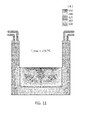
- Fig. 12 is a diagram of analyzing a heat distribution state on the front surface of the door body 10 when the door body 10 illustrated in Fig. 2 is simulated under the same conditions as the comparative example.
- Fig. 12 is a grayscale diagram outputting, with the monitor, the heat distribution for the front surface of the door body according to the present invention, when simulated using the simulation program. Referring to Fig. 12 , under the same conditions as the comparative example, it can be seen that the maximum temperature of the door body 10 according to the present invention of Fig. 2 is 249.6°C.
- the method of manufacturing the slag discharge door for the electric furnace according to the present invention further includes a surface treating step 400 of forming a high-hardness coating layer 60 on a slag contact surface of the door body 10 which is in contact with the slag.
- the slag contact surface includes the front surface of the door body 10 disposed towards the inside of the electric furnace, and the inner surface of the guide protrusion 11 through which the slag of the electric furnace passes.
- the high-hardness coating layer 60 is based on Fe-Cr coating, and other variants of forming high hardness coating are possible.
- the high-hardness coating layer 60 makes it easy to remove solidified slag 3, and minimizes abrasion on the slag contact surface as the cooled slag 3 is removed.
- the surface treating step 400 includes a welding coating operation of coating the high-hardness coating layer 60 on the slag contact surface of the door body 10 by welding;, and a surface grinding operation of grinding the high-hardness coating layer 60 formed at the welding coating operation.
- the surface treating step 400 further includes a preheating operation of preheating the door body 10, prior to the welding coating operation.
- the preheating operation preheats the door body 10 prior to the welding coating operation, thus allowing the coating layer to be more firmly fused on the surface of the door body 10 in the welding coating operation.
- the high-hardness coating layer 60 having the irregular and uneven surface by the welding coating operation is ground and smoothened by the surface grinding operation.
- the high-hardness coating layer 60 it is possible to form the high-hardness coating layer 60 either by metalizing or plating.
- the method of manufacturing the slag discharge door for the electric furnace 1 according to the present invention further includes a reinforcement manufacturing step 500 and a door assembling step 600.
- a door reinforcing body 20 is formed to be coupled with the door body 10 and thereby reinforce the door body 10.
- the door reinforcing body 20 manufactured at the reinforcement manufacturing step 500 is assembled with the door body 10.
- the door body 10 is made of metal having high heat conductivity, namely, copper material. Hence, when the door body moves up and down, the door body may be deformed or damaged by external shocks.
- the door main body 5 includes the door body 10 that is in direct contact with the slag and controls the discharge of the slag, and the door reinforcing body 20 that is coupled to the door body 10 to reinforce the door body 10, thus preventing thermal deformation due to high temperature of the slag, and ensuring rigidity sufficient for vertical movement, thus enabling stable operation.
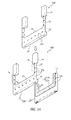
- the door reinforcing body 20 is coupled with the door body 10 to surround the lower surface of the door body 10, the outer surface of each guide protrusion 11, and the upper end of each guide protrusion 11, thus reinforcing the door body 10.
- the door reinforcing body 20 includes a base mounting plate 21, a lower support protrusion 22, guide mounting plates 23, and guide support protrusions 24.
- a rear surface of the door body 10 is mounted to the base mounting plate 21.
- the lower support protrusion 22 protrudes from a lower portion of the base mounting plate 21 in such a way as to support the lower portion of the door body 10.
- the guide mounting plates 23 protrude upwards from the base mounting plate 21 in such a way as to be spaced apart from each other, with rear surfaces of the guide protrusions 11 mounted to the guide mounting plates.
- the guide support protrusions 24 protrude from the guide mounting plates 23, respectively, to support the upper portions of the guide protrusions 11.
- the door reinforcing body is manufactured by casting using a steel material of high strength.
- a stepped portion 12 protrudes from the rear surface of the door body 10 in such a way as to be exposed through the base mounting plate 21 of the door reinforcing body 20.
- the stepped portion 12 includes a first stepped portion 12a that is provided on an upper portion of the door body 10, and second stepped portions 12b that extend from both ends of the first stepped portion 12a to the front surface of the guide protrusion 11.
- the stepped portion 12 is the slag contact surface that is in contact with the slag 2 flowing down along the rear surface of the door body 10 when opening or closing the slag discharge opening 1a.
- the stepped portion 12 is formed on the rear surface of the door body 10.
- the stepped portion 12 is preferably formed on the rear surface of the door body 10 in such a way as to be exposed through the base mounting plate 21 of the door reinforcing body 20.
- a bolt through hole 20a is formed in the door reinforcing body 20 to permit a bolt to pass therethrough.
- a fastening hole is formed in the door body 10 in such a way as to correspond to the bolt through hole 20a.
- the bolt through hole 20a may be formed at the reinforcement manufacturing step 500, and the fastening hole may be formed at the body forming step 100. Alternatively, the bolt through hole 20a and the fastening hole 10a may be formed at the door assembling step 600.
- the door body 10 is integrally coupled with the door reinforcing body 20 via the plurality of bolts that pass through the plurality of bolt through holes 20a formed in the base mounting plate 21 and the guide mounting plate 23 to be fastened to the door reinforcing body 20, thus forming the door main body 5.
- the present invention provides a method of manufacturing a slag discharge door, which enables the slag discharge door, namely, a door main body 5 to effectively dissipate heat from slag in the case of blocking the leakage of slag, thus minimizing deformation and damage due to the heat and thereby ensuring good durability and long service life, therefore allowing the slag discharge door to be stably used for a lengthy period of time.
Landscapes
- Engineering & Computer Science (AREA)
- Mechanical Engineering (AREA)
- General Engineering & Computer Science (AREA)
- Chemical & Material Sciences (AREA)
- Manufacturing & Machinery (AREA)
- Materials Engineering (AREA)
- Metallurgy (AREA)
- Organic Chemistry (AREA)
- Furnace Housings, Linings, Walls, And Ceilings (AREA)
- Vertical, Hearth, Or Arc Furnaces (AREA)
- Furnace Details (AREA)
- Elevator Door Apparatuses (AREA)
Applications Claiming Priority (2)
| Application Number | Priority Date | Filing Date | Title |
|---|---|---|---|
| KR1020110100005A KR101277817B1 (ko) | 2011-09-30 | 2011-09-30 | 슬래그 배출 도어 제조 방법 |
| PCT/KR2012/007636 WO2013048067A2 (fr) | 2011-09-30 | 2012-09-24 | Procédé de fabrication d'une porte de rejet de scories |
Publications (2)
| Publication Number | Publication Date |
|---|---|
| EP2762576A2 true EP2762576A2 (fr) | 2014-08-06 |
| EP2762576A4 EP2762576A4 (fr) | 2015-04-29 |
Family
ID=47996589
Family Applications (1)
| Application Number | Title | Priority Date | Filing Date |
|---|---|---|---|
| EP12836767.9A Withdrawn EP2762576A4 (fr) | 2011-09-30 | 2012-09-24 | Procédé de fabrication d'une porte de rejet de scories |
Country Status (6)
| Country | Link |
|---|---|
| US (1) | US9964360B2 (fr) |
| EP (1) | EP2762576A4 (fr) |
| JP (1) | JP5758542B2 (fr) |
| KR (1) | KR101277817B1 (fr) |
| CN (1) | CN103608471B (fr) |
| WO (1) | WO2013048067A2 (fr) |
Cited By (1)
| Publication number | Priority date | Publication date | Assignee | Title |
|---|---|---|---|---|
| CN104654821A (zh) * | 2015-03-13 | 2015-05-27 | 苏州圣谱拉新材料科技有限公司 | 一种侧边去渣式冶炼炉 |
Families Citing this family (3)
| Publication number | Priority date | Publication date | Assignee | Title |
|---|---|---|---|---|
| CN104006659A (zh) * | 2014-06-16 | 2014-08-27 | 岑溪市东正动力科技开发有限公司 | 一种冶金炉炉门上框边 |
| KR101617167B1 (ko) * | 2015-08-12 | 2016-05-03 | 한국수력원자력 주식회사 | 측면 배출게이트가 구비된 플라즈마 용융로 |
| CN108204586B (zh) * | 2018-01-17 | 2024-08-09 | 江苏新方圆电气设备制造有限公司 | 一种用于膜式冷渣机的能够快速放渣的筒体部件 |
Family Cites Families (24)
| Publication number | Priority date | Publication date | Assignee | Title |
|---|---|---|---|---|
| DE940835C (de) * | 1951-08-05 | 1956-03-29 | Georgsmarienhuette Ag | In den Kreislauf eines Kesselsystems eingeschalteter wassergekuehlter Tuerrahmen fuer Industrieoefen, wie Siemens-Martin-OEfen |
| DE1085903B (de) * | 1954-01-15 | 1960-07-28 | Mont Kessel Herpen & Co K G | Fuer Siemens-Martin-OEfen bestimmter gekuehlter Tuerrahmen mit einem Querbalken, dessen Hohlraum in einzelne, uebereinanderliegende, waagerechte Kuehlkanaele unterteilt ist |
| US4015834A (en) * | 1972-08-02 | 1977-04-05 | Engineered Metal Products Company, Inc. | Lifting bail for modular divisible metallurgical furnace shells |
| US4122295A (en) * | 1976-01-17 | 1978-10-24 | Ishikawajima-Harima Jukogyo Kabushiki Kaisha | Furnace wall structure capable of tolerating high heat load for use in electric arc furnace |
| DE2907511C2 (de) * | 1979-02-26 | 1986-03-20 | Kabel- und Metallwerke Gutehoffnungshütte AG, 3000 Hannover | Kühlplatte für Schachtöfen, insbesondere Hochöfen, und Verfahren zur Herstellung derselben |
| GB2064079A (en) * | 1979-11-30 | 1981-06-10 | British Steel Corp | Surface coated copper furnace components |
| FR2695715B1 (fr) * | 1992-09-11 | 1994-11-25 | Unimetall Sa | Porte de décrassage d'un four électrique à arc. |
| EP0705906B1 (fr) | 1994-10-07 | 2000-01-26 | Sms Schloemann-Siemag Aktiengesellschaft | Plaque de refroidissement pour fours à cuve |
| JP3867310B2 (ja) * | 1995-11-08 | 2007-01-10 | 石川島播磨重工業株式会社 | 製鋼用アーク炉の除滓口ドア装置 |
| JPH10317052A (ja) * | 1997-05-17 | 1998-12-02 | Nippon Steel Corp | マグネシア質耐火物で内張りされた溶融金属処理容器のリライニング方法 |
| JPH10316479A (ja) * | 1997-05-17 | 1998-12-02 | Nippon Steel Corp | 火炎溶射材 |
| KR200250763Y1 (ko) * | 1997-07-29 | 2001-12-13 | 이구택 | 냉각장치 및 자동개폐장치가 설치된 전로의 출강측도어 |
| KR19990038390A (ko) | 1997-11-04 | 1999-06-05 | 정몽규 | 냉난방 장치 |
| KR200306520Y1 (ko) * | 1998-03-24 | 2003-05-17 | 주식회사 만도 | 전기자동차용인버터 |
| JP2002062057A (ja) * | 2000-08-24 | 2002-02-28 | Nkk Corp | 冶金炉の炉壁冷却・保護方法及び炉壁冷却装置 |
| US7767137B2 (en) * | 2006-06-20 | 2010-08-03 | Empco (Canada) Ltd. | Sealing apparatus for a slag door of a metallurgical furnace |
| KR20080098113A (ko) * | 2007-05-04 | 2008-11-07 | 에이테크솔루션(주) | 병렬 냉각 시스템을 갖는 사출금형기 |
| WO2009037649A2 (fr) * | 2007-09-17 | 2009-03-26 | Metix (Pty) Limited | Voûte pour un four à arc électrique et son procédé de fabrication |
| KR101035508B1 (ko) * | 2008-10-28 | 2011-05-20 | 현대제철 주식회사 | 전기로 도어 |
| KR20100065849A (ko) * | 2008-12-09 | 2010-06-17 | 주식회사 서울엔지니어링 | 고로 출선구의 커버 |
| JP3156596U (ja) * | 2009-10-23 | 2010-01-07 | 三菱重工環境・化学エンジニアリング株式会社 | 水冷構造物 |
| KR101185211B1 (ko) * | 2009-12-29 | 2012-09-21 | 현대제철 주식회사 | 전기로의 슬래그 배출 도어 장치 |
| US8206642B2 (en) * | 2010-03-16 | 2012-06-26 | Process Technology International | Pivoting slag door |
| US9664444B2 (en) * | 2010-11-29 | 2017-05-30 | Hyundai Steel Company | Slag discharge door device for an electric furnace |
-
2011
- 2011-09-30 KR KR1020110100005A patent/KR101277817B1/ko active Active
-
2012
- 2012-09-24 JP JP2014513460A patent/JP5758542B2/ja active Active
- 2012-09-24 WO PCT/KR2012/007636 patent/WO2013048067A2/fr not_active Ceased
- 2012-09-24 CN CN201280028874.7A patent/CN103608471B/zh active Active
- 2012-09-24 EP EP12836767.9A patent/EP2762576A4/fr not_active Withdrawn
-
2013
- 2013-12-04 US US14/096,834 patent/US9964360B2/en active Active
Cited By (2)
| Publication number | Priority date | Publication date | Assignee | Title |
|---|---|---|---|---|
| CN104654821A (zh) * | 2015-03-13 | 2015-05-27 | 苏州圣谱拉新材料科技有限公司 | 一种侧边去渣式冶炼炉 |
| CN104654821B (zh) * | 2015-03-13 | 2016-08-17 | 苏州圣谱拉新材料科技有限公司 | 一种侧边去渣式冶炼炉 |
Also Published As
| Publication number | Publication date |
|---|---|
| CN103608471A (zh) | 2014-02-26 |
| WO2013048067A3 (fr) | 2013-05-23 |
| US9964360B2 (en) | 2018-05-08 |
| WO2013048067A2 (fr) | 2013-04-04 |
| US20140290026A1 (en) | 2014-10-02 |
| JP5758542B2 (ja) | 2015-08-05 |
| KR101277817B1 (ko) | 2013-06-21 |
| JP2014519590A (ja) | 2014-08-14 |
| EP2762576A4 (fr) | 2015-04-29 |
| CN103608471B (zh) | 2015-05-20 |
| KR20130035605A (ko) | 2013-04-09 |
Similar Documents
| Publication | Publication Date | Title |
|---|---|---|
| CN102472579B (zh) | 用于电炉的排渣门装置 | |
| US9964360B2 (en) | Method of manufacturing a slag discharge door | |
| CN102971438B (zh) | 枢转的渣门 | |
| US20140035209A1 (en) | Ladle metallurgy furnace having improved roof | |
| JP5735125B2 (ja) | 電気炉のスラグ排出ドア装置 | |
| KR101225260B1 (ko) | 전기로의 슬래그 배출 도어 구조체 | |
| KR20120079053A (ko) | 전기로 | |
| KR101257611B1 (ko) | 전기로의 슬래그 배출 도어 구조체 | |
| RU2450228C1 (ru) | Держатель инжектора и способ его эксплуатации | |
| KR101225325B1 (ko) | 전기로의 슬래그 배출 도어 장치 | |
| JP3429754B1 (ja) | 金型の製造方法 | |
| KR101229273B1 (ko) | 열전도성과 내마모성이 우수한 고로 냉각반 및 그 제조방법 | |
| KR20080099673A (ko) | 가열로 내부의 차단장치 | |
| KR101035508B1 (ko) | 전기로 도어 | |
| KR101148914B1 (ko) | 용강 배출장치 | |
| AT410717B (de) | Kühlplatte mit verstärkungsteil | |
| CN219103674U (zh) | 一种真空冷却罐及其内胆 | |
| KR20120037405A (ko) | 전기로 안의 금속의 재용해 방법 및 장치 | |
| KR20180057415A (ko) | 슬라이드 게이트의 침지노즐 마운팅 구조 | |
| JPH06328221A (ja) | 金属溶解保持炉 | |
| JP6420473B2 (ja) | 乾式冶金炉の堰モジュール | |
| KR101451723B1 (ko) | 전극봉 산화 방지 장치 | |
| KR101159964B1 (ko) | 전기로 출강구 개폐장치 | |
| CN203964679U (zh) | 受料口装置 | |
| KR20100065849A (ko) | 고로 출선구의 커버 |
Legal Events
| Date | Code | Title | Description |
|---|---|---|---|
| PUAI | Public reference made under article 153(3) epc to a published international application that has entered the european phase |
Free format text: ORIGINAL CODE: 0009012 |
|
| 17P | Request for examination filed |
Effective date: 20131203 |
|
| AK | Designated contracting states |
Kind code of ref document: A2 Designated state(s): AL AT BE BG CH CY CZ DE DK EE ES FI FR GB GR HR HU IE IS IT LI LT LU LV MC MK MT NL NO PL PT RO RS SE SI SK SM TR |
|
| DAX | Request for extension of the european patent (deleted) | ||
| A4 | Supplementary search report drawn up and despatched |
Effective date: 20150401 |
|
| RIC1 | Information provided on ipc code assigned before grant |
Ipc: F27B 3/19 20060101ALI20150326BHEP Ipc: F27D 1/12 20060101ALI20150326BHEP Ipc: C21C 5/52 20060101AFI20150326BHEP |
|
| STAA | Information on the status of an ep patent application or granted ep patent |
Free format text: STATUS: THE APPLICATION HAS BEEN WITHDRAWN |
|
| 18W | Application withdrawn |
Effective date: 20170216 |