EP2762660A2 - Gâche de logement d'un pêne - Google Patents
Gâche de logement d'un pêne Download PDFInfo
- Publication number
- EP2762660A2 EP2762660A2 EP13188018.9A EP13188018A EP2762660A2 EP 2762660 A2 EP2762660 A2 EP 2762660A2 EP 13188018 A EP13188018 A EP 13188018A EP 2762660 A2 EP2762660 A2 EP 2762660A2
- Authority
- EP
- European Patent Office
- Prior art keywords
- inner part
- pin
- receiving part
- bolt receiving
- door
- Prior art date
- Legal status (The legal status is an assumption and is not a legal conclusion. Google has not performed a legal analysis and makes no representation as to the accuracy of the status listed.)
- Withdrawn
Links
Images




Classifications
-
- E—FIXED CONSTRUCTIONS
- E05—LOCKS; KEYS; WINDOW OR DOOR FITTINGS; SAFES
- E05C—BOLTS OR FASTENING DEVICES FOR WINGS, SPECIALLY FOR DOORS OR WINDOWS
- E05C9/00—Arrangements of simultaneously actuated bolts or other securing devices at well-separated positions on the same wing
- E05C9/18—Details of fastening means or of fixed retaining means for the ends of bars
- E05C9/1825—Fastening means
- E05C9/1875—Fastening means performing pivoting movements
-
- E—FIXED CONSTRUCTIONS
- E05—LOCKS; KEYS; WINDOW OR DOOR FITTINGS; SAFES
- E05B—LOCKS; ACCESSORIES THEREFOR; HANDCUFFS
- E05B15/00—Other details of locks; Parts for engagement by bolts of fastening devices
- E05B15/02—Striking-plates; Keepers; Bolt staples; Escutcheons
- E05B15/0205—Striking-plates, keepers, staples
- E05B15/022—Striking-plates, keepers, staples movable, resilient or yieldable
-
- E—FIXED CONSTRUCTIONS
- E05—LOCKS; KEYS; WINDOW OR DOOR FITTINGS; SAFES
- E05B—LOCKS; ACCESSORIES THEREFOR; HANDCUFFS
- E05B15/00—Other details of locks; Parts for engagement by bolts of fastening devices
- E05B15/02—Striking-plates; Keepers; Bolt staples; Escutcheons
- E05B15/0205—Striking-plates, keepers, staples
- E05B15/024—Striking-plates, keepers, staples adjustable
- E05B2015/026—Striking-plates, keepers, staples adjustable using eccentrics
Definitions
- the invention relates to a latch receiving part for a door lock, with an outer part which can be fastened to a door frame and / or a closing strip and an inner part which is movably arranged in the outer part and into which a latch of the door lock engages in the closed state of the door, wherein the inner part by means of a spring device in a basic position is held, from which the inner part along the closing direction of the door against the spring force of the spring device is deflected.
- the door lock is in practice on a door, preferably a revolving or hinged door, but possibly also attached to a sliding door, while the corresponding locking strip is attached to the door frame or a door frame.
- the closing strip is referred to in practice as a strike plate, they can, for. B. may be formed as a flat plate or as an angle plate with L-shaped or U-shaped cross-section. It has at least one opening in which engages the latch of the door lock in the locked state of the door.
- the latch receiving part is therefore preferably attached in the region of such opening of the locking strip on the door frame and / or the closing strip, so that the latch of the door lock engages in the locked state of the door through the locking bar in the (pot-like) latch receiving part.
- the positioning of the locking bar or a bolt receiving part is in practice of particular importance, because with different profile systems and rubber seals, there is a need to assemble a closure member in different positions, so that the locking elements of the door, z. B. or the pivot bolt can properly engage in the closing part.
- the adjustment also takes place so that the one or more bolts, the door, z. B. Door, always gently pull in the door seal.
- doors, z. B. wooden doors or plastic doors warp due to the different weather or temperature conditions.
- a latch receiving part for a door lock which has an outer part and an inner part disposed therein, wherein the inner part is held by a spring means in a basic position, from which the inner part is deflected against the spring force of the spring means.
- the inner part it may be z.
- B. is a cross-sectionally L-shaped lever which is pivotally held in the outer part. In this way it should be ensured that z. B. a latch can always properly engage in a locking plate or a closing part.
- the invention has for its object to provide a latch receiving part for a door lock of the type described above, which is variable with a simple and inexpensive construction and ensures proper locking of the door.
- the invention teaches a latch receiving part for a door lock, with an attachable to a door frame and / or a closing strip outer part and an outer part movably arranged inner part, in which a latch of the door lock engages in the closed or locked state of the door, wherein the inner part is held by means of a spring device in a basic position, from which the inner part along the closing direction of the door against the spring force of the spring device is deflectable, and wherein the basic position of the inner part is variable with an adjusting device.
- the inner part is held pivotably about a pivot axis in the outer part, which is oriented parallel to the engagement direction of the bolt.
- the invention is based on the recognition that the problems occurring in practice, which result from the distortion of the door in the event of temperature fluctuations, can be avoided in a simple and reliable manner when a latch receiving part with a sprung inner part is made available. With the help of the sprung inner part can be misalignments and in particular a door delay due to temperature fluctuations or other reasons completely or at least partially from the closing part.
- the latch receiving part or closing part according to the invention is characterized by a variable use, because the inner part is not only sprung relative to the outer part, but the basic position of the inner part can be changed with an adjusting device, so that the ring receiving part or its basic position to different Profile systems and rubber seals can be adjusted.
- the latch receiving part according to the invention is thus characterized by the combination of suspension on the one hand and adjustability on the other. It is presettable and self-adjusting.
- Such a latch receiving part is particularly preferred for additional locking a multi-point lock, z. B. a drive rod lock used. Because in practice there is a multiple locking z. B. have a center lock and upper and lower auxiliary locks, the problem that just changed the position of the additional locks in the delay of a door.
- the bolt receiving part can also be used in the area of a center lock or a mortise lock.
- the latch receiving part is designed as a pot-like latch receiving part, which z. B. is mounted in the region of an opening of a closing strip, preferably arranged on the back side of the closing strip.
- the outer part of the latch receiving part is pot-shaped and preferably provided with one or more fastening projections for the attachment of the bolt receiving part to a door frame and / or on a closing strip.
- the inner part may preferably be provided with an adjusting projection, wherein in the region of this adjusting projection then the adjusting device is arranged, with which the basic position of the inner part is variable.
- the adjusting device has an eccentric part, which is arranged on the one hand in the outer part along the closing direction movable or displaceable and on the other hand is rotatably attached to the inner part to change the basic position.
- the eccentric part is preferably supported on the spring device, so that the extension part changes the position of the inner part in the course of the rotation, without spring deflection, d. H. the inner part is transferred by rotation of the Exzenterteils in a changed basic position.
- the inner part is pivoted in the course of rotation of the eccentric about the pivot axis A, which is oriented parallel to the engagement direction of the bolt.
- the inner part is supported by the adjusting device, for. B. the eccentric, on the spring device.
- the eccentric z. B. have a first (lower) pin on which the spring device operates and a second (upper) pin which is connected to the inner part, wherein the second upper pin is rotatable to change the basic position about a rotation axis D which is offset from the is arranged first pin, so that in the course of rotation of the second pin due to the on the first Journal operating spring device, the position of the second pin along the closing direction X is changed and thus the inner part is pivoted. Consequently, the basic part of the inner part can be changed in a simple manner with the eccentric part and consequently adapted to a specific installation position. After adjustment is then due to the spring means still the possibility that the inner part is deflected against the spring force of the spring means, so that still a spring-loaded closing part is provided.
- the eccentric between the first pin and the second pin has an intermediate part, the z. B. disc-shaped may be formed as an intermediate disc and rests on the inner part.
- the eccentric part may be formed as a one-piece component. So it is within the scope of the invention that the first pin, the second pin and optionally the intermediate part are integrally connected to form the eccentric part.
- the eccentric is not “loose” rotatably disposed in the inner part, but the eccentric is locked, ie it is retained in the respective rotational position in a recess of the inner part.
- This can be z. B. be realized via a latching configuration in which z. B. the eccentric and / or a corresponding recess of the inner part corresponding latching elements. This allows an adjustment option to be created in stages.
- it is also within the scope of the invention to provide a continuous adjustment in which the eccentric is rotatably held on the inner part, but as it were frictionally so that a clamping locking is ensured in the respective position.
- any other locking options of Exzenterteils on the inner part for defining the rotational position are encompassed by the invention.
- the inner part is held about a pivot axis A pivotally in the outer part, which operates parallel to the engagement direction Z of the bolt.
- the adjusting device for. B. the eccentric part, on which the pivot axis opposite end of the inner part or outer part is arranged.
- the spring device is arranged on the opposite end of the pivot axis of the inner part or outer part.
- the inner part is actually hinged via a suitable pin rotatably on the outer part.
- the outer part may have an inner arcuate support surface, on which the inner part is rotatably supported by an outer arcuate support surface. The pot-like inner part is thus inserted into the cup-like outer part and by appropriate adaptation of the contours, a rotatable or pivotable arrangement of the inner part is realized in the outer part.
- the spring device acts from two opposite directions on the adjusting device, for. B. on the eccentric part, so that the deflection is sprung in both directions of the closing direction Y.
- This is preferably realized by two compression springs, which are arranged along the closing direction Y and from opposite directions on the adjusting device, for. B. the eccentric, work. It can be two separate compression springs.
- the spring device is preferably designed as a one-piece spring device, ie the two compression springs are z. B. on a back Connecting bracket to a common spring means (or a double pressure spring) connected together.
- the subject of the invention is therefore to a particular extent the bolt receiving part, which is provided independently under protection. It is in practice z. B. attached to a door frame, but it can alternatively be attached to the back of a closing strip.
- Closing strip means in the context of the invention, a "short" strike plate or a closing plate, which can also form a cover plate for the bolt receiving pot. It may be appropriate to attach the closing strip or a cover plate separately also on the door frame. It may, for. B. be useful to introduce the closing strip or the cover plate with vertical screws in the door frame, while the bolt receiving pot, in principle, for. B. the outer part or lower part is fixed with obliquely oriented screws.
- the locking strip not only has a (usual) opening for the bolt, but also an opening through which a tool in the region of the bolt receiving pot is inserted to the adjusting device, for , B. the eccentric to operate.
- the latch receiving part according to the invention is preferably provided separately under protection.
- the invention also includes a closing part for a door lock, with a closing strip and a latch receiving part of the described Art.
- the combination of closing strip and latch receiving part which is generally referred to as a closing part, is therefore also provided in combination under protection.
- closing strip it may be z. B. to act a special cover plate for the latch receiving part.
- the subject of the invention is also a locking system with at least one door lock and at least one such closing part.
- the locking system is preferably an espagnolette lock with multiple locking and consequently with a center lock and auxiliary locks, at least one closing part being provided for such an additional lock, but preferably one closing part for an additional lock and possibly also for one center lock.
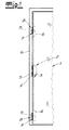
- a locking system with multiple locking for a door 1 is shown.
- the multiple locking is formed in the embodiment as espagnolette lock 2 with a central lock 3 and additional locks 4, wherein each of the locks has at least one latch 5, which is shown in the additional locks 4 in the embodiment as a pivot bolt, but can also be configured differently.
- closing strips 7 are fixed, which is each equipped with recesses for the locking elements of the espagnolette lock 2.
- individual closure strips or strike plates for a center lock on the one hand and the additional locks on the other hand are provided.
- a latch receiving part 8 is attached to the door frame 6 in the region of the additional locks 4.
- the closing strip 7 for the additional lock 4 forms a cover plate for the latch receiving part 8.
- this is a "sprung" bolt receiving part, so that misalignments and, in particular, a distortion of the door (eg due to temperature fluctuations) can be absorbed by the bolt receiving part.
- the latch receiving part 8 on an outer part 9, which is attached to the rear side of the door frame 6.
- an inner part 10 is movably arranged.
- the inner part 10 engages the latch 5 of the auxiliary lock 4 in the locked state of the door.
- the inner part 10 is by means of a spring device 11 is held in a basic position, from which the inner part 10 along the closing direction Y of the door against the spring force of the spring means 11 is deflectable.
- the closing direction Y is perpendicular to the closing strip longitudinal direction X and perpendicular to the engagement direction Z of the bolt 5.
- the closing strip plane is thus spanned by the closing direction Y and the closing strip longitudinal direction X, wherein the closing direction Y substantially corresponds to the closing strip transverse direction.
- the inner part 10 is held pivotably about a pivot axis A in the outer part 9, wherein the pivot axis A, which is indicated only schematically in the figures, is oriented parallel to the engagement direction Z of the bolt 5.
- the outer part 9 is pot-shaped. It has upper and lower side fastening projections 9a, which are provided in the embodiment with openings through which the latch receiving part 8 is fixed to the door frame 6. Also, the inner part 10 is pot-shaped in the embodiment, this cup-like inner part 10 is inserted into the cup-shaped outer part 9.
- the latch receiving part 8 is not only sprung, but also adjustable and thus adjustable. Because the basic position of the inner part 10 is changeable with an adjusting device 12 and therefore adjustable. In this way, it is possible to adjust the latch receiving part 8 to different profile systems and rubber seals, so that the latch 5 always pull the door 1 perfectly and gently into the seal. This succeeds according to the invention without the bolt receiving part 8 itself must be mounted in different positions on the frame or the closing strip and the simultaneous possibility of suspension and thus the tolerance compensation.
- the adjusting device 12 has in the exemplary embodiment on an eccentric 13, which is arranged on the one hand in the outer part 9 along the closing direction Y movable or displaceable and on the other hand rotatably attached to the inner part 10 for changing the basic position.
- the eccentric 13 changes in the course of rotation, the position of the inner part 10 without the spring device 11 is deflected, d. H. the inner part remains in a (changed) basic position.
- the eccentric 13 By actuation of the eccentric 13, therefore, the basic position is varied and in this basic position then there is still the possibility that the inner part 10 is deflected along the closing direction Y against the spring force of the spring means 11.
- the eccentric part 13 has a first lower pin 13a, on which the spring device 11 operates.
- the eccentric 13 has a second upper pin 13 b, which is connected to the inner part 10.
- the second pin 13b is rotatable about a rotational axis D for changing the basic position, this rotational axis D being offset from the first pin 13a, so that in the course of the rotation of the second pin 13b the position of the pinion 13a acts on the first pin 13a second pin 13b along the closing direction X is changed and thus the inner part 10 is pivoted.
- the eccentric part 13 between the first pin 13a and the second pin 13b has an intermediate part 13c, which in the exemplary embodiment is disk-shaped and on which the inner part 10 rests.
- the eccentric 13, which consists in the embodiment of the first pin 13a, second pin 13b and washer 13c is made in one piece.
- the adjusting device 12 is arranged with the eccentric part 13 at the opposite end of the pivot axis A of the inner part 10 and also of the outer part 9.
- the spring device 11 is arranged on the end of the inner part 10, which is also opposite the pivot axis A, and also of the outer part 9.
- the inner part 10 has a fastening projection 10b in which the recess 10a for the eccentric element is arranged.
- the pivotable arrangement of the inner part 10 within the outer part 9 is realized in the embodiment by corresponding corresponding arcuate support surfaces 15, 16.
- the outer part 9 has an inner arcuate support surface 15, on which the inner part 10 is rotatably supported by an outer arcuate support surface 16.
- the spring device 11 has two compression springs 11a, 11b which operate from opposite directions on the adjusting device 12, namely on the eccentric part 13.
- the spring force of the spring device 11, namely the two compression springs 11a, 11b is aligned along the closing direction Y.
- a one-piece spring device 11 is realized, that is, the compression springs 11a, 11b are connected via a connecting bracket 11 c to a common double pressure spring together.
- the invention is shown in the embodiment with reference to the additional lock 4. However, it can alternatively or additionally be realized in the region of a central lock, and not only in the area of a bolt, but also in the area of a lock latch.
- the latch receiving part 8 is not attached directly to the closing strip 7, but the latch receiving part is fastened with screws on the door frame.
- the closing strip 7 or the cover plate is also fastened with separate screws on the door frame.
- the latch pot is fastened with obliquely oriented screws
- the closing strip 7 is usually fastened with screws oriented vertically to the locking bar plane. Details are not shown.
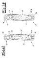
- Fig. 4a, 4b show the latch receiving part 8 (without closing strip or cover plate) in a plan view, wherein the inner part 10 is adjusted in a "center position".
- the inner part 10 is adjusted in a "center position".
- Fig. 4a illustrated basic position (zero position) is thus the inner part 10 centrally in the outer part.
- Fig. 4b shows in this adjustment the case in which the inner part 10 is deflected by the engagement of the bolt 5 maximum.
- a comparative analysis of the Fig. 4a, 4b shows that misalignments can be compensated by a deflection of the inner part 10.
- Fig. 6a shows a "loose position”.
- the eccentric was rotated 90 ° from the center position clockwise.
- Fig. 6a again shows the adjusted basic position, in which the compression springs are not loaded. Subsequently, the inner part 10 can escape through the engaging latch 5, as well as in Fig. 6b is shown.
- the closing strip 7 has, moreover, in a basically known manner, an opening for the latch 5, so that the bolt, z. B. pivot bolt, engages through this opening in the region of the bolt receiving part.
- the closing strip 7 has an opening 17, through which a suitable tool in the region of the adjusting device can be inserted.
- the adjusting device with an Allen key is adjustable, so that this Allen key (not shown) through the opening (slot 17) can be pushed through.
Landscapes
- Engineering & Computer Science (AREA)
- Mechanical Engineering (AREA)
- Closing And Opening Devices For Wings, And Checks For Wings (AREA)
- Lock And Its Accessories (AREA)
- Hinges (AREA)
Applications Claiming Priority (1)
| Application Number | Priority Date | Filing Date | Title |
|---|---|---|---|
| DE102013101033.4A DE102013101033A1 (de) | 2013-02-01 | 2013-02-01 | Riegelaufnahmeteil |
Publications (2)
| Publication Number | Publication Date |
|---|---|
| EP2762660A2 true EP2762660A2 (fr) | 2014-08-06 |
| EP2762660A3 EP2762660A3 (fr) | 2015-10-14 |
Family
ID=49378091
Family Applications (1)
| Application Number | Title | Priority Date | Filing Date |
|---|---|---|---|
| EP13188018.9A Withdrawn EP2762660A3 (fr) | 2013-02-01 | 2013-10-10 | Gâche de logement d'un pêne |
Country Status (2)
| Country | Link |
|---|---|
| EP (1) | EP2762660A3 (fr) |
| DE (1) | DE102013101033A1 (fr) |
Cited By (5)
| Publication number | Priority date | Publication date | Assignee | Title |
|---|---|---|---|---|
| EP3067490A1 (fr) | 2015-03-12 | 2016-09-14 | Aug. Winkhaus GmbH & Co. KG | Tole de fermeture pour une ferrure de bielle |
| CN106246019A (zh) * | 2015-06-08 | 2016-12-21 | 泷源制造株式会社 | 多点紧固式锁定系统以及使用了该多点紧固式锁定系统的防爆门 |
| EP3205795A1 (fr) * | 2016-02-15 | 2017-08-16 | ASSA ABLOY Nederland B.V. | Loquet et procédé de déclenchement d'un élément de verrouillage |
| EP3222800A1 (fr) * | 2016-03-23 | 2017-09-27 | ASSA ABLOY Nederland B.V. | Cliquet pour encliqueterun élément de verrouillage |
| EP3527757A1 (fr) * | 2018-02-14 | 2019-08-21 | Gretsch-Unitas GmbH Baubeschläge | Système de fermeture à verrou et installation de porte |
Families Citing this family (4)
| Publication number | Priority date | Publication date | Assignee | Title |
|---|---|---|---|---|
| JP6356001B2 (ja) * | 2014-07-28 | 2018-07-11 | 文化シヤッター株式会社 | 対震ストライク付引戸 |
| DE102018118388A1 (de) | 2018-07-30 | 2020-01-30 | Carl Fuhr Gmbh & Co. Kg | Riegelaufnahmevorrichtung |
| DE202021100537U1 (de) | 2021-02-03 | 2021-02-16 | Carl Fuhr GmbH & Co. KG. | Schließteilanordnung |
| DE102022209496A1 (de) | 2022-09-12 | 2024-03-14 | Roto Frank Fenster- und Türtechnologie GmbH | Schließstück für eine Schließleistenanordnung einer Gebäudeverschlusseinrichtung, entsprechende Schließleistenanordnung sowie Verfahren zum Montieren eines Schließstücks |
Citations (1)
| Publication number | Priority date | Publication date | Assignee | Title |
|---|---|---|---|---|
| EP2447452A1 (fr) | 2010-10-26 | 2012-05-02 | Buva Rationele Bouwprodukten Bv | Gâche de verrou, ensemble d'une gâche et d'un verrou et/ou d'un élément de fermeture et procédé pour fermer un élément de fermeture |
Family Cites Families (3)
| Publication number | Priority date | Publication date | Assignee | Title |
|---|---|---|---|---|
| GB1077609A (en) * | 1965-12-22 | 1967-08-02 | Raymond Adam Rosenberger | Improvements in adjustable striking plates |
| GB2247275A (en) * | 1990-08-24 | 1992-02-26 | Securistyle Ltd | An adjustable fitting |
| NL1037972C2 (nl) * | 2010-05-19 | 2011-11-29 | Themans Hang En Sluitwerk B V | Sluitkom en vergrendelinrichting omvattende een dergelijke sluitkom. |
-
2013
- 2013-02-01 DE DE102013101033.4A patent/DE102013101033A1/de not_active Withdrawn
- 2013-10-10 EP EP13188018.9A patent/EP2762660A3/fr not_active Withdrawn
Patent Citations (1)
| Publication number | Priority date | Publication date | Assignee | Title |
|---|---|---|---|---|
| EP2447452A1 (fr) | 2010-10-26 | 2012-05-02 | Buva Rationele Bouwprodukten Bv | Gâche de verrou, ensemble d'une gâche et d'un verrou et/ou d'un élément de fermeture et procédé pour fermer un élément de fermeture |
Cited By (11)
| Publication number | Priority date | Publication date | Assignee | Title |
|---|---|---|---|---|
| EP3067490A1 (fr) | 2015-03-12 | 2016-09-14 | Aug. Winkhaus GmbH & Co. KG | Tole de fermeture pour une ferrure de bielle |
| DE102015204508A1 (de) | 2015-03-12 | 2016-09-15 | Aug. Winkhaus Gmbh & Co. Kg | Schließblech für einen Treibstangenbeschlag |
| CN106246019A (zh) * | 2015-06-08 | 2016-12-21 | 泷源制造株式会社 | 多点紧固式锁定系统以及使用了该多点紧固式锁定系统的防爆门 |
| JP2017005042A (ja) * | 2015-06-08 | 2017-01-05 | タキゲン製造株式会社 | 多点締め込み式ロックシステム及びこれを用いた防爆扉 |
| TWI633232B (zh) * | 2015-06-08 | 2018-08-21 | 瀧源製造股份有限公司 | 多點緊固式鎖系統及使用該鎖系統的防爆門 |
| CN106246019B (zh) * | 2015-06-08 | 2019-03-01 | 泷源制造株式会社 | 多点紧固式锁定系统以及使用了该多点紧固式锁定系统的防爆门 |
| EP3205795A1 (fr) * | 2016-02-15 | 2017-08-16 | ASSA ABLOY Nederland B.V. | Loquet et procédé de déclenchement d'un élément de verrouillage |
| NL2016263B1 (en) * | 2016-02-15 | 2017-08-22 | Assa Abloy Nederland B V | Catch and a method for catching a locking element. |
| EP3222800A1 (fr) * | 2016-03-23 | 2017-09-27 | ASSA ABLOY Nederland B.V. | Cliquet pour encliqueterun élément de verrouillage |
| NL2016481A (en) * | 2016-03-23 | 2017-10-02 | Assa Abloy Nederland B V | Catch for catching a locking element. |
| EP3527757A1 (fr) * | 2018-02-14 | 2019-08-21 | Gretsch-Unitas GmbH Baubeschläge | Système de fermeture à verrou et installation de porte |
Also Published As
| Publication number | Publication date |
|---|---|
| DE102013101033A1 (de) | 2014-08-07 |
| EP2762660A3 (fr) | 2015-10-14 |
Similar Documents
| Publication | Publication Date | Title |
|---|---|---|
| EP2762660A2 (fr) | Gâche de logement d'un pêne | |
| DE202012002741U1 (de) | Beschlag für einen zumindest annähernd parallel abstellbaren und in dieser Parallelabstelllage horizontal verschiebbaren Flügel von Fenstern oder Türen | |
| EP2754813B1 (fr) | Charnière, notamment pour portes et fenêtres en plastique | |
| EP2245252A1 (fr) | Palier d'angle réglable pour vantail d'une fenêtre, d'une porte ou similaire | |
| EP1411201B1 (fr) | Ferrure | |
| DE2458800C2 (de) | Schnappvorrichtung | |
| EP2113624A2 (fr) | Dispositif de fixation de porte ou de fenêtre | |
| WO2015067540A1 (fr) | Porte coulissante ou fenêtre coulissante | |
| EP3183408B1 (fr) | Élément de commande pour système de ferrure | |
| DE8711496U1 (de) | Verschluß für zweiflügelige Fenster, Türen od. dgl. | |
| DE10056607C1 (de) | Fehlbedienungssperre für Treibstangenbeschläge | |
| EP4573251A1 (fr) | Dispositif de décalage permettant le décalage forcé d'un battant, en particulier d'un battant coulissant, d'une fenêtre ou d'une porte | |
| EP2511463B1 (fr) | Fenêtre, porte ou analogue pourvue d'un dispositif d'amortissement | |
| DE102007025857A1 (de) | Gelenkband für Türen oder Fenster | |
| EP0234213A2 (fr) | Tringle de commande | |
| DE2729394A1 (de) | Verriegelungseinrichtung fuer fenster, tueren o.dgl. | |
| DE102015209145B3 (de) | Beschlag sowie Verfahren zum Herstellen eines Beschlags | |
| EP0128429B2 (fr) | Tringlerie de commande pour fenêtres, portes ou similaires | |
| DE102007056626A1 (de) | Drehstangenverschluss, insbesondere für Schwenktüren von Kraftfahrzeugaufbauten | |
| EP3626918B1 (fr) | Ferrure pour une fenêtre, fenêtre | |
| DE8218084U1 (de) | Spaltlueftungsvorrichtung fuer fenster, tueren od. dgl. | |
| EP3339544B1 (fr) | Armature basculante pour un vantail de fenêtre ou de porte | |
| DE4236431A1 (fr) | ||
| EP1582672B1 (fr) | Renvoi d'angle pour ventilation réglable et limitation d'ouverture dans une condamnation centrale | |
| EP3350394A1 (fr) | Ferrure du type crémone |
Legal Events
| Date | Code | Title | Description |
|---|---|---|---|
| PUAI | Public reference made under article 153(3) epc to a published international application that has entered the european phase |
Free format text: ORIGINAL CODE: 0009012 |
|
| 17P | Request for examination filed |
Effective date: 20131010 |
|
| AK | Designated contracting states |
Kind code of ref document: A2 Designated state(s): AL AT BE BG CH CY CZ DE DK EE ES FI FR GB GR HR HU IE IS IT LI LT LU LV MC MK MT NL NO PL PT RO RS SE SI SK SM TR |
|
| AX | Request for extension of the european patent |
Extension state: BA ME |
|
| PUAL | Search report despatched |
Free format text: ORIGINAL CODE: 0009013 |
|
| AK | Designated contracting states |
Kind code of ref document: A3 Designated state(s): AL AT BE BG CH CY CZ DE DK EE ES FI FR GB GR HR HU IE IS IT LI LT LU LV MC MK MT NL NO PL PT RO RS SE SI SK SM TR |
|
| AX | Request for extension of the european patent |
Extension state: BA ME |
|
| RIC1 | Information provided on ipc code assigned before grant |
Ipc: E05C 9/18 20060101ALI20150910BHEP Ipc: E05B 15/02 20060101AFI20150910BHEP |
|
| R17P | Request for examination filed (corrected) |
Effective date: 20151124 |
|
| RBV | Designated contracting states (corrected) |
Designated state(s): AL AT BE BG CH CY CZ DE DK EE ES FI FR GB GR HR HU IE IS IT LI LT LU LV MC MK MT NL NO PL PT RO RS SE SI SK SM TR |
|
| GRAP | Despatch of communication of intention to grant a patent |
Free format text: ORIGINAL CODE: EPIDOSNIGR1 |
|
| INTG | Intention to grant announced |
Effective date: 20170207 |
|
| STAA | Information on the status of an ep patent application or granted ep patent |
Free format text: STATUS: THE APPLICATION IS DEEMED TO BE WITHDRAWN |
|
| 18D | Application deemed to be withdrawn |
Effective date: 20170620 |