EP2762664B1 - Zur Befestigung in einer Hinterschneidungen aufweisenden Führungsnut eines Flügels vorgesehene Eckumlenkung - Google Patents
Zur Befestigung in einer Hinterschneidungen aufweisenden Führungsnut eines Flügels vorgesehene Eckumlenkung Download PDFInfo
- Publication number
- EP2762664B1 EP2762664B1 EP13196436.3A EP13196436A EP2762664B1 EP 2762664 B1 EP2762664 B1 EP 2762664B1 EP 13196436 A EP13196436 A EP 13196436A EP 2762664 B1 EP2762664 B1 EP 2762664B1
- Authority
- EP
- European Patent Office
- Prior art keywords
- guide
- corner
- angle
- guide groove
- angle guide
- Prior art date
- Legal status (The legal status is an assumption and is not a legal conclusion. Google has not performed a legal analysis and makes no representation as to the accuracy of the status listed.)
- Active
Links
Images

Classifications
-
- E—FIXED CONSTRUCTIONS
- E05—LOCKS; KEYS; WINDOW OR DOOR FITTINGS; SAFES
- E05C—BOLTS OR FASTENING DEVICES FOR WINGS, SPECIALLY FOR DOORS OR WINDOWS
- E05C9/00—Arrangements of simultaneously actuated bolts or other securing devices at well-separated positions on the same wing
- E05C9/24—Means for transmitting movements between vertical and horizontal sliding bars, rods or cables for the fastening of wings, e.g. corner guides
-
- E—FIXED CONSTRUCTIONS
- E05—LOCKS; KEYS; WINDOW OR DOOR FITTINGS; SAFES
- E05D—HINGES OR SUSPENSION DEVICES FOR DOORS, WINDOWS OR WINGS
- E05D15/00—Suspension arrangements for wings
- E05D15/48—Suspension arrangements for wings allowing alternative movements
- E05D15/52—Suspension arrangements for wings allowing alternative movements for opening about a vertical as well as a horizontal axis
- E05D15/5208—Suspension arrangements for wings allowing alternative movements for opening about a vertical as well as a horizontal axis with means for transmitting movements between vertical and horizontal sliding bars, rods or cables
-
- E—FIXED CONSTRUCTIONS
- E05—LOCKS; KEYS; WINDOW OR DOOR FITTINGS; SAFES
- E05F—DEVICES FOR MOVING WINGS INTO OPEN OR CLOSED POSITION; CHECKS FOR WINGS; WING FITTINGS NOT OTHERWISE PROVIDED FOR, CONCERNED WITH THE FUNCTIONING OF THE WING
- E05F7/00—Accessories for wings not provided for in other groups of this subclass
- E05F7/08—Means for transmitting movements between vertical and horizontal sliding bars, rods, or cables
-
- E—FIXED CONSTRUCTIONS
- E05—LOCKS; KEYS; WINDOW OR DOOR FITTINGS; SAFES
- E05Y—INDEXING SCHEME ASSOCIATED WITH SUBCLASSES E05D AND E05F, RELATING TO CONSTRUCTION ELEMENTS, ELECTRIC CONTROL, POWER SUPPLY, POWER SIGNAL OR TRANSMISSION, USER INTERFACES, MOUNTING OR COUPLING, DETAILS, ACCESSORIES, AUXILIARY OPERATIONS NOT OTHERWISE PROVIDED FOR, APPLICATION THEREOF
- E05Y2600/00—Mounting or coupling arrangements for elements provided for in this subclass
- E05Y2600/50—Mounting methods; Positioning
- E05Y2600/52—Toolless
- E05Y2600/53—Snapping
-
- E—FIXED CONSTRUCTIONS
- E05—LOCKS; KEYS; WINDOW OR DOOR FITTINGS; SAFES
- E05Y—INDEXING SCHEME ASSOCIATED WITH SUBCLASSES E05D AND E05F, RELATING TO CONSTRUCTION ELEMENTS, ELECTRIC CONTROL, POWER SUPPLY, POWER SIGNAL OR TRANSMISSION, USER INTERFACES, MOUNTING OR COUPLING, DETAILS, ACCESSORIES, AUXILIARY OPERATIONS NOT OTHERWISE PROVIDED FOR, APPLICATION THEREOF
- E05Y2900/00—Application of doors, windows, wings or fittings thereof
- E05Y2900/10—Application of doors, windows, wings or fittings thereof for buildings or parts thereof
- E05Y2900/13—Type of wing
- E05Y2900/148—Windows
Definitions
- the invention relates to a provided for attachment in an undercuts guide groove of a wing provided Eckumlenkung an espagnolette fitting a window, a French window or the like, with a flexible deflection, with an angle guide for the deflection, arranged with a longitudinal side of the angle guide for engaging in the Undercut trained holding lug, wherein the angle guide is narrower than the guide groove and the angle guide is supported by a filler and the filler and the angle guide together have the width of the guide groove before the undercut.
- the DE 82 01 403 U1 discloses a corner drive for espagnolettes of windows, is designed to be bendable in a guide channel for the flexible deflection in an arcuate transition region.
- An angle housing forming legs have two molded parts which are interconnected.
- the DE 69 42 006 U discloses an arrangement of corner fitting parts in profile frames of windows, in which a corner fitting part is overlapped by a securing element. The securing element is screwed to the corner fitting.
- the DE 21 58 948 A1 discloses a corner drive for espagnolettes in which one leg is outwardly has protruding bar. A molding engages next to this leg under the heels of a guide channel.
- a Eckumlenkung is for example from the DE 20 15 723 C3 known.
- each movable retaining lugs are arranged on both sides of the long sides of the angle guide.
- retaining lugs are held in a retracted position.
- the retaining lugs are pushed out and penetrate into the undercut of the guide groove.
- the retaining lugs are arranged on elastic tongues. Screws or slides make it possible to push out the retaining lugs.
- a disadvantage of the known Eckumlenkung is that it has only low holding forces because of the elastic tongues. Furthermore, the assembly is very complex by the operation of the screws or slide.
- the invention is based on the problem, a corner drive of the type mentioned so on to form that it can be particularly easily and permanently attached to the guide.
- the filler has a bracket and that the bracket embraces a guide groove projecting portion of the angle guide.
- the corner drive is permanently secured in the guide groove.
- the corner drive has a uniform and easy-to-clean surface, because the bracket of the filler conceals the guide slot projecting portion of the angle guide.
- the bracket and the filler is made in one piece.
- the Eckumlenkung is composed of few components and can be particularly easy to assemble according to another advantageous embodiment of the invention, when the angle guide is made in one piece with two legs arranged at right angles to each other and if each leg has a single cover and if the covers in each case with one piece a filler are made.
- the filler and the angle guide could be biased by means of separately mounted clamping means within the guide.
- separately mounted clamping means can be according to another advantageous embodiment of the invention easily avoided if the filler and / or the angle guide an inherent elasticity to have their bias against the walls of the guide groove.
- the Eckumlenkung is reliably maintained in the guide groove according to another advantageous embodiment of the invention, when the filler has a trained for engaging in the undercut retaining lug and when the retaining lugs of the filler and the angle guide are diametrically away from each other.
- the filler and the angle guide with the holding lugs wider than the guide so that the retaining lugs penetrate into the undercut of the guide and hold the corner deflection reliable in the guide.
- the Eckumlenkung designed in accordance with another advantageous embodiment of the invention structurally particularly simple when the holding lug is designed as a nose-shaped elevation.
- the filler is reliably held according to another advantageous embodiment of the invention at the corner deflection when the filler has a bracket and when the bracket embraces a guide groove projecting portion of the angle guide.
- the bracket is preferably resiliently biased against the angle guide.
- the corner drive according to the invention has, according to another advantageous embodiment of the invention, a particularly high stability, when the angle guide and the filler have mutually corresponding grooves and webs.
- the mounting of the corner deflection designed according to another advantageous embodiment of the invention is particularly simple when the filler and the angle guide are connected in the separated state of the guide groove via a latching connection.
- the filler and the angle guide are fixed to each other and can be easily transported in the interconnected state and attached to the guide of the window.
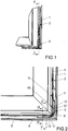
- FIG. 1 shows the wing 1 of a window with an espagnolette fitting 2.
- the espagnolette fitting 2 has a corner drive. 3
- FIG. 2 shows a sectional view through the wing 1 with the corner 3 from FIG. 1 along the line II - II.
- the espagnolette fitting 2 has two drive rod sections 4, 5, whose movements are coupled via a deflecting element 6 of the corner 3.
- the deflection element 3 has for connection to the drive rod sections 4, 5 each connecting pieces 7, 8.
- the corner drive 3 has a guide groove 9 of the wing 1 arranged angle guide 10 for the deflection 6.
- the angle guide 10 is integral with two mutually perpendicular legs 11th '11' designed. Each leg 11, 11 'of the angle guide 10 is covered by a cover 12, 12'.
- FIG. 3 shows a sectional view through the corner 3 from FIG. 2 along the line III - III with adjacent areas of the wing 1.
- the guide groove 9 has on both sides undercuts 13, 14, in the diametrically away from each other facing retaining lugs 15, 16 of the corner 3 penetrate.
- One of the retaining lugs 15 is made in one piece with the angle guide 10.
- the other holding lug 16 is arranged on a filler 17.
- the filler 17 and the angle guide 10 have before the retaining lugs 15, 16, the width of the guide groove 9.
- the filler 17 is made in one piece with the cover 12 and has a bracket 18, with which it overlaps a guide groove 9 superior portion of the angle guide 10.
- the filler 17 is designed resiliently with the bracket 18, so that the angle guide 10 is clasped.
- FIG. 4 shows the corner drive 3 from FIG. 3 During assembly in the guide groove 9.
- the angle guide 10 is inserted into the guide groove 9 until the retaining lug 15 of the angle guide 10 engages in an undercut 13.
- the filler 17 is pushed over the angle guide 10. The filler 17 is displaced perpendicular to the leg 11 of the angle guide 10 and compared to the one leg 11 of the angle guide 10 via mutually corresponding grooves 19 and webs 20 until the retaining lug 16 of the filler 17 snaps into the other undercut 14.
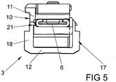
- FIG. 5 shows a further sectional view through the corner 3 from FIG. 2 along the line V - V before mounting in the in FIG. 3
- the filling piece 17 is connected via a latching connection 21 with the angle guide 10.
Landscapes
- Engineering & Computer Science (AREA)
- Mechanical Engineering (AREA)
- Window Of Vehicle (AREA)
- Operating, Guiding And Securing Of Roll- Type Closing Members (AREA)
- Reinforcement Elements For Buildings (AREA)
- Rear-View Mirror Devices That Are Mounted On The Exterior Of The Vehicle (AREA)
- Installation Of Indoor Wiring (AREA)
Description
- Die Erfindung betrifft eine zur Befestigung in einer Hinterschneidungen aufweisenden Führungsnut eines Flügels vorgesehene Eckumlenkung eines Treibstangenbeschlages eines Fensters, einer Fenstertür oder dergleichen, mit einem flexiblen Umlenkelement, mit einer Winkelführung für das Umlenkelement, mit einem an einer Längsseite der Winkelführung angeordneten, zum Eingriff in die Hinterschneidung ausgebildeten Halteansatz, wobei die Winkelführung schmaler ist als die Führungsnut und die Winkelführung von einem Füllstück abgestützt ist und das Füllstück und die Winkelführung gemeinsam die Breite der Führungsnut vor der Hinterschneidung aufweisen.
- Die
DE 82 01 403 U1 offenbart eine Eckumlenkung für Treibstangenbeschläge von Fenstern, bei ein Führungskanal für das flexible Umlenkelement in einem bogenförmigen Übergangsbereich biegeverformbar gestaltet ist. Ein Winkelgehäuse bildende Schenkel weisen zwei Formteile auf, die miteinander verbunden sind. - Die
DE 69 42 006 U offenbart eine Anordnung von Eckbeschlagteilen in Profilrahmen von Fenstern, bei dem ein Eckbeschlagteil von einem Sicherungselement übergriffen ist. Das Sicherungselement ist mit dem Eckbeschlagteil verschraubt. - Die
DE 21 58 948 A1 offenbart eine Eckumlenkung für Treibstangenbeschläge, bei dem ein Schenkel eine nach außen abstehende Leiste aufweist. Ein Formteil greift neben diesem Schenkel unter die Absätze eines Führungskanals. - Eine Eckumlenkung ist beispielsweise aus der
DE 20 15 723 C3 bekannt. Bei dieser Eckumlenkung sind beidseitig an den Längsseiten der Winkelführung jeweils bewegliche Halteansätze angeordnet. Zur Montage der Eckumlenkung an der Führungsnut sind die Halteansätze in einer zurückgezogenen Position gehalten. Nach dem Einsetzen der Eckumlenkung in die Führungsnut werden die Halteansätze hervorgeschoben und dringen in die Hinterschneidung der Führungsnut ein. Die Halteansätze sind auf elastischen Zungen angeordnet. Schrauben oder Schieber ermöglichen das Hervorschieben der Halteansätze. Nachteilig bei der bekannten Eckumlenkung ist, dass sie wegen der elastischen Zungen nur geringe Haltekräfte aufweist. Weiterhin gestaltet sich durch die Betätigung der Schrauben oder Schieber die Montage sehr aufwändig. - Aus der
DE 24 56 009 C2 ist eine Befestigung der Eckumlenkung eines Treibstangenbeschlages bekannt geworden, bei der ein Z-förmiger Befestigungswinkel an der Winkelführung gelagert ist. Der Befestigungswinkel ist elastisch gestaltet und spannt die Winkelführung gegen eine Wandung der Führungsnut vor. Dabei dringt ein Halteansatz der Winkelführung in die Hinterschneidung der Führungsnut ein. Nachteilig bei dieser Befestigung ist, dass sich der Befestigungswinkel durch Betriebskräfte des Fensters lösen kann. - Der Erfindung liegt das Problem zugrunde, eine Eckumlenkung der eingangs genannten Art so weiter zu bilden, dass sie besonders einfach und dauerhaft in der Führungsnut befestigt werden kann.
- Dieses Problem wird erfindungsgemäß dadurch gelöst, dass das Füllstück einen Bügel hat und dass der Bügel einen die Führungsnut überragenden Abschnitt der Winkelführung umklammert.
- Durch diese Gestaltung ist die Eckumlenkung zwischen den Wandungen der Führungsnut gehalten. Da das Füllstück und die Winkelführung die Breite der Führungsnut aufweisen und der Halteansatz in die Hinterschneidung der Führungsnut eindringt, ist die Eckumlenkung dauerhaft in der Führungsnut befestigt. Die Eckumlenkung lässt sich hierdurch besonders einfach und dauerhaft in der Führungsnut befestigen. Die Eckumlenkung weist eine einheitliche und leicht zu reinigende Oberfläche auf, weil der Bügel des Füllstücks den die Führungsnut überragenden Abschnitt der Winkelführung verdeckt. Vorzugsweise ist der Bügel und das Füllstück einstückig gefertigt.
- Die Eckumlenkung setzt sich aus wenigen Bauteilen zusammen und lässt sich gemäß einer anderen vorteilhaften Weiterbildung der Erfindung besonders einfach montieren, wenn die Winkelführung einstückig mit zwei rechtwinklig zueinander angeordneten Schenkeln gefertigt ist und wenn jeder der Schenkel eine einzelne Abdeckung hat und wenn die Abdeckungen jeweils einstückig mit einem Füllstück gefertigt sind.
- Das Füllstück und die Winkelführung könnten mittels separat zu montierender Spannmittel innerhalb der Führungsnut vorgespannt sein. Solche separat zu montierenden Spannmittel lassen sich jedoch gemäß einer anderen vorteilhaften Weiterbildung der Erfindung einfach vermeiden, wenn das Füllstück und/oder die Winkelführung eine Eigenelastizität zu ihrer Vorspannung gegen die Wandungen der Führungsnut aufweisen.
- Die Eckumlenkung ist gemäß einer anderen vorteilhaften Weiterbildung der Erfindung zuverlässig in der Führungsnut gehalten, wenn das Füllstück einen zum Eingriff in die Hinterschneidung ausgebildeten Halteansatz aufweist und wenn die Halteansätze des Füllstücks und der Winkelführung diametral voneinander weg weisen. Durch diese Gestaltung sind das Füllstück und die Winkelführung mit den Halteansätzen breiter als die Führungsnut, so dass die Halteansätze in die Hinterschneidung der Führungsnut eindringen und die Eckumlenkung zuverlässig in der Führungsnut halten.
- Die Eckumlenkung gestaltet sich gemäß einer anderen vorteilhaften Weiterbildung der Erfindung konstruktiv besonders einfach, wenn der Halteansatz als nasenförmige Erhebung ausgebildet ist.
- Das Füllstück ist gemäß einer anderen vorteilhaften Weiterbildung der Erfindung zuverlässig an der Eckumlenkung gehalten, wenn das Füllstück einen Bügel hat und wenn der Bügel einen die Führungsnut überragenden Abschnitt der Winkelführung umklammert. Für die Umklammerung ist der Bügel vorzugsweise federelastisch gegen die Winkelführung vorgespannt.
- Die erfindungsgemäße Eckumlenkung weist gemäß einer anderen vorteilhaften Weiterbildung der Erfindung eine besonders hohe Stabilität auf, wenn die Winkelführung und das Füllstück miteinander korrespondierende Nuten und Stege aufweisen.
- Die Montage der Eckumlenkung gestaltet sich gemäß einer anderen vorteilhaften Weiterbildung der Erfindung besonders einfach, wenn das Füllstück und die Winkelführung im von der Führungsnut getrennten Zustand über eine Rastverbindung miteinander verbunden sind. Durch diese Gestaltung sind das Füllstück und die Winkelführung aneinander fixiert und können im miteinander verbundenen Zustand einfach transportiert und an der Führungsnut des Fensters angesetzt werden.
- Die Erfindung lässt zahlreiche Ausführungsformen zu. Zur weiteren Verdeutlichung ihres Grundprinzips ist eine davon in der Zeichnung dargestellt und wird nachfolgend beschrieben. Diese zeigt in
- Fig. 1
- einen Teilbereich eines Flügels eines Fensters mit einer erfindungsgemäßen Eckumlenkung,
- Fig. 2
- einen Längsschnitt durch die Eckumlenkung aus
Figur 1 entlang der Linie II - II, - Fig. 3
- eine Schnittdarstellung durch die Eckumlenkung aus
Figur 2 entlang der Linie III - III, - Fig. 4
- die Eckumlenkung aus
Figur 3 bei der Montage am Flügel, - Fig. 5
- eine Schnittdarstellung durch die Eckumlenkung aus
Figur 2 entlang der Linie II - II. -
Figur 1 zeigt den Flügel 1 eines Fensters mit einem Treibstangenbeschlag 2. Der Treibstangenbeschlag 2 hat eine Eckumlenkung 3. -
Figur 2 zeigt eine Schnittdarstellung durch den Flügel 1 mit der Eckumlenkung 3 ausFigur 1 entlang der Linie II - II. Der Treibstangenbeschlag 2 hat zwei Treibstangenabschnitte 4, 5, deren Bewegungen über ein Umlenkelement 6 der Eckumlenkung 3 gekoppelt sind. Das Umlenkelement 6 hat zur Verbindung mit den Treibstangenabschnitten 4, 5 jeweils Anschlussstücke 7, 8. Die Eckumlenkung 3 hat eine in einer Führungsnut 9 des Flügels 1 angeordnete Winkelführung 10 für das Umlenkelement 6. Die Winkelführung 10 ist einstückig mit zwei rechtwinklig zueinander angeordneten Schenkeln 11, 11' gestaltet. Jeder Schenkel 11, 11' der Winkelführung 10 wird von einer Abdeckung 12, 12' überdeckt. -
Figur 3 zeigt eine Schnittdarstellung durch die Eckumlenkung 3 ausFigur 2 entlang der Linie III - III mit angrenzenden Bereichen des Flügels 1. Hierbei ist zu erkennen, dass die Führungsnut 9 beidseitig Hinterschneidungen 13, 14 hat, in die diametral voneinander weg weisende Halteansätze 15, 16 der Eckumlenkung 3 eindringen. Einer der Halteansätze 15 ist einstückig mit der Winkelführung 10 gefertigt. Der andere Halteansatz 16 ist auf einem Füllstück 17 angeordnet. Das Füllstück 17 und die Winkelführung 10 haben vor den Halteansätzen 15, 16 die Breite der Führungsnut 9. Das Füllstück 17 ist einstückig mit der Abdeckung 12 gefertigt und hat einen Bügel 18, mit dem es einen die Führungsnut 9 überragenden Abschnitt der Winkelführung 10 übergreift. Das Füllstück 17 ist mit dem Bügel 18 federelastisch gestaltet, so dass die Winkelführung 10 umklammert ist. -
Figur 4 zeigt die Eckumlenkung 3 ausFigur 3 während der Montage in der Führungsnut 9. Zunächst wird die Winkelführung 10 in die Führungsnut 9 eingesetzt, bis der Halteansatz 15 der Winkelführung 10 in die eine Hinterschneidung 13 eingreift. Anschließend wird das Füllstück 17 über die Winkelführung 10 geschoben. Dabei wird das Füllstück 17 senkrecht zu dem Schenkel 11 der Winkelführung 10 verschoben und gegenüber dem einen Schenkel 11 der Winkelführung 10 über miteinander korrespondierende Nuten 19 und Stege 20 geführt bis der Halteansatz 16 des Füllstücks 17 in die andere Hinterschneidung 14 einschnappt. -
Figur 5 zeigt eine weitere Schnittdarstellung durch die Eckumlenkung 3 ausFigur 2 entlang der Linie V - V vor der Montage in der inFigur 3 dargestellten Führungsnut 9. Das Füllstück 17 ist über eine Rastverbindung 21 mit der Winkelführung 10 verbunden.
Claims (8)
- Zur Befestigung in einer Hinterschneidungen (13, 14) aufweisenden Führungsnut (9) eines Flügels (1) vorgesehene Eckumlenkung (3) eines Treibstangenbeschlages (2) eines Fensters, einer Fenstertür oder dergleichen, mit einem flexiblen Umlenkelement (6), mit einer Winkelführung (10) für das Umlenkelement (6), mit einem an einer Längsseite der Winkelführung (10) angeordneten, zum Eingriff in die Hinterschneidung (13, 14) ausgebildeten Halteansatz (15, 16), wobei die Winkelführung (10) schmaler ist als die Führungsnut (9), und wobei die Winkelführung (10) von einem Füllstück (17) abgestützt ist und das Füllstück (17) und die Winkelführung (10) gemeinsam die Breite der Führungsnut (9) vor der Hinterschneidung (13, 14) aufweisen, dadurch gekennzeichnet, dass das Füllstück (17) einen Bügel (18) hat und dass der Bügel (18) einen die Führungsnut (9) überragenden Abschnitt der Winkelführung (10) umklammert.
- Eckumlenkung nach Anspruch 1, dadurch gekennzeichnet, dass die Winkelführung (10) einstückig mit zwei rechtwinklig zueinander angeordneten Schenkeln (11, 11') gefertigt ist und dass jeder der Schenkel (11, 11') eine einzelne Abdeckung (12, 12') hat und dass die Abdeckungen (12, 12') jeweils einstückig mit einem Füllstück (17) gefertigt sind.
- Eckumlenkung nach Anspruch 1 oder 2, dadurch gekennzeichnet, dass das Füllstück (17) und/oder die Winkelführung (10) eine Eigenelastizität zu ihrer Vorspannung gegen die Wandungen der Führungsnut (9) aufweisen.
- Eckumlenkung nach einem der Ansprüche 1 bis 3, dadurch gekennzeichnet, dass das Füllstück (17) einen zum Eingriff in die Hinterschneidung (13, 14) ausgebildeten Halteansatz (15, 16) aufweist und dass die Halteansätze (15, 16) des Füllstücks (17) und der Winkelführung (10) diametral voneinander weg weisen.
- Eckumlenkung nach einem der Ansprüche 1 bis 4, dadurch gekennzeichnet, dass der Halteansatz (15, 16) als nasenförmige Erhebung ausgebildet ist.
- Eckumlenkung nach Anspruch 1, dadurch gekennzeichnet, dass der Bügel (18) des Füllstücks (17) den die Führungsnut (9) überragenden Abschnitt der Winkelführung (10) verdeckt.
- Eckumlenkung nach einem der Ansprüche 1 bis 6, dadurch gekennzeichnet, dass die Winkelführung (10) und das Füllstück (17) miteinander korrespondierende Nuten (19) und Stege (20) aufweisen.
- Eckumlenkung nach einem der Ansprüche 1 bis 7, dadurch gekennzeichnet, dass das Füllstück (17) und die Winkelführung (10) im von der Führungsnut (9) getrennten Zustand über eine Rastverbindung (21) miteinander verbunden sind.
Priority Applications (1)
| Application Number | Priority Date | Filing Date | Title |
|---|---|---|---|
| PL13196436T PL2762664T3 (pl) | 2013-01-30 | 2013-12-10 | Zwrotnica przeznaczona do mocowania w zawierającym podcięcia rowku prowadzącym skrzydła |
Applications Claiming Priority (1)
| Application Number | Priority Date | Filing Date | Title |
|---|---|---|---|
| DE102013201521.6A DE102013201521A1 (de) | 2013-01-30 | 2013-01-30 | Zur Befestigung in einer Hinterschneidungen aufweisenden Führungsnut eines Flügels vorgesehene Eckumlenkung |
Publications (3)
| Publication Number | Publication Date |
|---|---|
| EP2762664A2 EP2762664A2 (de) | 2014-08-06 |
| EP2762664A3 EP2762664A3 (de) | 2017-05-24 |
| EP2762664B1 true EP2762664B1 (de) | 2019-02-27 |
Family
ID=49766914
Family Applications (1)
| Application Number | Title | Priority Date | Filing Date |
|---|---|---|---|
| EP13196436.3A Active EP2762664B1 (de) | 2013-01-30 | 2013-12-10 | Zur Befestigung in einer Hinterschneidungen aufweisenden Führungsnut eines Flügels vorgesehene Eckumlenkung |
Country Status (5)
| Country | Link |
|---|---|
| EP (1) | EP2762664B1 (de) |
| DE (1) | DE102013201521A1 (de) |
| ES (1) | ES2718313T3 (de) |
| PL (1) | PL2762664T3 (de) |
| TR (1) | TR201904543T4 (de) |
Cited By (1)
| Publication number | Priority date | Publication date | Assignee | Title |
|---|---|---|---|---|
| DE102021203760B3 (de) | 2021-04-15 | 2022-04-07 | Roto Frank Fenster- und Türtechnologie GmbH | Beschlag mit einem durch Längsschieben arretierbaren Rasthaken |
Families Citing this family (2)
| Publication number | Priority date | Publication date | Assignee | Title |
|---|---|---|---|---|
| FR3054585B1 (fr) * | 2016-07-29 | 2018-08-10 | Jh Ind | Dispositif de fermeture d'une baie coulissante comportant une partie manoeuvrante integree dans un chassis de dormant |
| FR3054584B1 (fr) * | 2016-07-29 | 2019-11-01 | Jh Industries | Dispositif de fermeture d'une baie coulissante comportant un boitier de manœuvre et une gache integres dans un chassis de dormant |
Family Cites Families (4)
| Publication number | Priority date | Publication date | Assignee | Title |
|---|---|---|---|---|
| DE8201403U1 (de) * | 1982-05-19 | Siegenia-Frank Kg, 5900 Siegen | Eckumlenkung für Treibstangenbeschläge von Fenstern, Türen od. dgl. | |
| DE6942006U (de) * | 1969-10-28 | 1970-03-05 | Ver Baubeschlag Gretsch Co | Anordnung von eckbeschlagteilen, insbesondere von kettenwinkeln, in profilrahmen von fenstern, tueren od.dgl. |
| DE2158948C3 (de) * | 1971-11-27 | 1982-01-14 | Siegenia-Frank Kg, 5900 Siegen | Eckbeschlag für Fenster und Türen od. dgl., insbesondere Eckumlenkung für Treibstangenbeschläge |
| DE2456009C2 (de) | 1974-11-27 | 1983-09-08 | Wilh. Frank Gmbh, 7022 Leinfelden-Echterdingen | Befestigung eines Gehäuses einer Eckumlenkung von Treibstangenbeschlägen |
-
2013
- 2013-01-30 DE DE102013201521.6A patent/DE102013201521A1/de not_active Withdrawn
- 2013-12-10 EP EP13196436.3A patent/EP2762664B1/de active Active
- 2013-12-10 ES ES13196436T patent/ES2718313T3/es active Active
- 2013-12-10 PL PL13196436T patent/PL2762664T3/pl unknown
- 2013-12-10 TR TR2019/04543T patent/TR201904543T4/tr unknown
Non-Patent Citations (1)
| Title |
|---|
| None * |
Cited By (2)
| Publication number | Priority date | Publication date | Assignee | Title |
|---|---|---|---|---|
| DE102021203760B3 (de) | 2021-04-15 | 2022-04-07 | Roto Frank Fenster- und Türtechnologie GmbH | Beschlag mit einem durch Längsschieben arretierbaren Rasthaken |
| EP4074931A1 (de) | 2021-04-15 | 2022-10-19 | Roto Frank Fenster- und Türtechnologie GmbH | Beschlag mit einem durch längsschieben arretierbaren rasthaken |
Also Published As
| Publication number | Publication date |
|---|---|
| TR201904543T4 (tr) | 2019-04-22 |
| PL2762664T3 (pl) | 2019-09-30 |
| ES2718313T3 (es) | 2019-07-01 |
| EP2762664A3 (de) | 2017-05-24 |
| DE102013201521A1 (de) | 2014-07-31 |
| EP2762664A2 (de) | 2014-08-06 |
Similar Documents
| Publication | Publication Date | Title |
|---|---|---|
| DE3815927C2 (de) | ||
| DE202011003000U1 (de) | Wischblatt und Endkappe | |
| DE102011051291A1 (de) | Steckverbinder mit Kammerblock und Kontaktsicherung | |
| DE112008002568T5 (de) | Stoßfängerbefestigungsclip | |
| EP2762664A2 (de) | Zur Befestigung in einer Hinterschneidungen aufweisenden Führungsnut eines Flügels vorgesehene Eckumlenkung | |
| DE3108212C2 (de) | Eckumlenkung von Treibstangenbeschlägen an Fenstern, Türen oder dgl. | |
| DE2743796A1 (de) | Fernbetaetigung, insbesondere fuer die starterklappe von kraftfahrzeugen | |
| EP3462084A1 (de) | Led-leuchte | |
| DE102016207083A1 (de) | Einrichtung zur Abstützung eines eine längsverschiebliche Treibstange aufweisenden Beschlagteils | |
| WO2013000799A1 (de) | Verbindungshülse zur verbindung von rohren mit weiteren bauteilen | |
| DE102009025771A1 (de) | Gleiter für Gardinenschienen | |
| DE102008054672A1 (de) | Kupplung zur Anbindung einer ein über zwei Schenkel geführtes Federband aufweisenden Eckumlenkung an einem längsverschieblichen Treibstangenabschnitt | |
| EP2620936B1 (de) | Leuchte mit Rahmenelement | |
| DE102010042629A1 (de) | Halteelement eines Beschlagteils eines Treibstangenbeschlages | |
| DE2660436B2 (de) | Verbundprofil, insbesondere für Fenster, Türen, Fassaden o.dgl. | |
| DE102011002810A1 (de) | Drehlager | |
| EP2581532B1 (de) | Eckumlenkung für einen Treibstangenbeschlag eines Fensters | |
| DE102012218339A1 (de) | Vorrichtung zum Verbinden von wenigstens zwei Elementen | |
| EP3067495B1 (de) | Haltelement eines beschlagteils eines treibstangenbeschlages | |
| DE102014217711B4 (de) | Kulissenanordnung für eine Beschlagteilanordnung | |
| DE102012001644A1 (de) | Fensterführungsvorrichtung | |
| EP0637791B1 (de) | Dichtleiste für einen Schiebesteller | |
| AT402126B (de) | Vorrichtung zum befestigen eines elektrischen schaltgerätes auf einer tragschiene | |
| DE2015723C3 (de) | Befestigung einer Eckumlenkung für Treibstangen von Treibstangenverschlüssen, insbesondere von Kipp-Schwenkflügel-Beschlägen, für Fenster, Türen o.dgl | |
| DE102017201250A1 (de) | Eckumlenkung für einen Treibstangenbeschlag |
Legal Events
| Date | Code | Title | Description |
|---|---|---|---|
| PUAI | Public reference made under article 153(3) epc to a published international application that has entered the european phase |
Free format text: ORIGINAL CODE: 0009012 |
|
| 17P | Request for examination filed |
Effective date: 20131210 |
|
| AK | Designated contracting states |
Kind code of ref document: A2 Designated state(s): AL AT BE BG CH CY CZ DE DK EE ES FI FR GB GR HR HU IE IS IT LI LT LU LV MC MK MT NL NO PL PT RO RS SE SI SK SM TR |
|
| AX | Request for extension of the european patent |
Extension state: BA ME |
|
| PUAL | Search report despatched |
Free format text: ORIGINAL CODE: 0009013 |
|
| AK | Designated contracting states |
Kind code of ref document: A3 Designated state(s): AL AT BE BG CH CY CZ DE DK EE ES FI FR GB GR HR HU IE IS IT LI LT LU LV MC MK MT NL NO PL PT RO RS SE SI SK SM TR |
|
| AX | Request for extension of the european patent |
Extension state: BA ME |
|
| RIC1 | Information provided on ipc code assigned before grant |
Ipc: E05C 9/24 20060101AFI20170418BHEP Ipc: E05D 15/52 20060101ALI20170418BHEP Ipc: E05F 7/08 20060101ALI20170418BHEP |
|
| STAA | Information on the status of an ep patent application or granted ep patent |
Free format text: STATUS: REQUEST FOR EXAMINATION WAS MADE |
|
| R17P | Request for examination filed (corrected) |
Effective date: 20171010 |
|
| RBV | Designated contracting states (corrected) |
Designated state(s): AL AT BE BG CH CY CZ DE DK EE ES FI FR GB GR HR HU IE IS IT LI LT LU LV MC MK MT NL NO PL PT RO RS SE SI SK SM TR |
|
| GRAP | Despatch of communication of intention to grant a patent |
Free format text: ORIGINAL CODE: EPIDOSNIGR1 |
|
| STAA | Information on the status of an ep patent application or granted ep patent |
Free format text: STATUS: GRANT OF PATENT IS INTENDED |
|
| INTG | Intention to grant announced |
Effective date: 20181019 |
|
| GRAS | Grant fee paid |
Free format text: ORIGINAL CODE: EPIDOSNIGR3 |
|
| GRAA | (expected) grant |
Free format text: ORIGINAL CODE: 0009210 |
|
| STAA | Information on the status of an ep patent application or granted ep patent |
Free format text: STATUS: THE PATENT HAS BEEN GRANTED |
|
| AK | Designated contracting states |
Kind code of ref document: B1 Designated state(s): AL AT BE BG CH CY CZ DE DK EE ES FI FR GB GR HR HU IE IS IT LI LT LU LV MC MK MT NL NO PL PT RO RS SE SI SK SM TR |
|
| REG | Reference to a national code |
Ref country code: GB Ref legal event code: FG4D Free format text: NOT ENGLISH |
|
| REG | Reference to a national code |
Ref country code: CH Ref legal event code: EP |
|
| REG | Reference to a national code |
Ref country code: AT Ref legal event code: REF Ref document number: 1101578 Country of ref document: AT Kind code of ref document: T Effective date: 20190315 |
|
| REG | Reference to a national code |
Ref country code: IE Ref legal event code: FG4D Free format text: LANGUAGE OF EP DOCUMENT: GERMAN |
|
| REG | Reference to a national code |
Ref country code: DE Ref legal event code: R096 Ref document number: 502013012285 Country of ref document: DE |
|
| REG | Reference to a national code |
Ref country code: NL Ref legal event code: FP |
|
| REG | Reference to a national code |
Ref country code: ES Ref legal event code: FG2A Ref document number: 2718313 Country of ref document: ES Kind code of ref document: T3 Effective date: 20190701 |
|
| REG | Reference to a national code |
Ref country code: LT Ref legal event code: MG4D |
|
| PG25 | Lapsed in a contracting state [announced via postgrant information from national office to epo] |
Ref country code: LT Free format text: LAPSE BECAUSE OF FAILURE TO SUBMIT A TRANSLATION OF THE DESCRIPTION OR TO PAY THE FEE WITHIN THE PRESCRIBED TIME-LIMIT Effective date: 20190227 Ref country code: FI Free format text: LAPSE BECAUSE OF FAILURE TO SUBMIT A TRANSLATION OF THE DESCRIPTION OR TO PAY THE FEE WITHIN THE PRESCRIBED TIME-LIMIT Effective date: 20190227 Ref country code: NO Free format text: LAPSE BECAUSE OF FAILURE TO SUBMIT A TRANSLATION OF THE DESCRIPTION OR TO PAY THE FEE WITHIN THE PRESCRIBED TIME-LIMIT Effective date: 20190527 Ref country code: PT Free format text: LAPSE BECAUSE OF FAILURE TO SUBMIT A TRANSLATION OF THE DESCRIPTION OR TO PAY THE FEE WITHIN THE PRESCRIBED TIME-LIMIT Effective date: 20190627 Ref country code: SE Free format text: LAPSE BECAUSE OF FAILURE TO SUBMIT A TRANSLATION OF THE DESCRIPTION OR TO PAY THE FEE WITHIN THE PRESCRIBED TIME-LIMIT Effective date: 20190227 |
|
| PG25 | Lapsed in a contracting state [announced via postgrant information from national office to epo] |
Ref country code: RS Free format text: LAPSE BECAUSE OF FAILURE TO SUBMIT A TRANSLATION OF THE DESCRIPTION OR TO PAY THE FEE WITHIN THE PRESCRIBED TIME-LIMIT Effective date: 20190227 Ref country code: LV Free format text: LAPSE BECAUSE OF FAILURE TO SUBMIT A TRANSLATION OF THE DESCRIPTION OR TO PAY THE FEE WITHIN THE PRESCRIBED TIME-LIMIT Effective date: 20190227 Ref country code: IS Free format text: LAPSE BECAUSE OF FAILURE TO SUBMIT A TRANSLATION OF THE DESCRIPTION OR TO PAY THE FEE WITHIN THE PRESCRIBED TIME-LIMIT Effective date: 20190627 Ref country code: GR Free format text: LAPSE BECAUSE OF FAILURE TO SUBMIT A TRANSLATION OF THE DESCRIPTION OR TO PAY THE FEE WITHIN THE PRESCRIBED TIME-LIMIT Effective date: 20190528 Ref country code: HR Free format text: LAPSE BECAUSE OF FAILURE TO SUBMIT A TRANSLATION OF THE DESCRIPTION OR TO PAY THE FEE WITHIN THE PRESCRIBED TIME-LIMIT Effective date: 20190227 Ref country code: BG Free format text: LAPSE BECAUSE OF FAILURE TO SUBMIT A TRANSLATION OF THE DESCRIPTION OR TO PAY THE FEE WITHIN THE PRESCRIBED TIME-LIMIT Effective date: 20190527 |
|
| PG25 | Lapsed in a contracting state [announced via postgrant information from national office to epo] |
Ref country code: SK Free format text: LAPSE BECAUSE OF FAILURE TO SUBMIT A TRANSLATION OF THE DESCRIPTION OR TO PAY THE FEE WITHIN THE PRESCRIBED TIME-LIMIT Effective date: 20190227 Ref country code: EE Free format text: LAPSE BECAUSE OF FAILURE TO SUBMIT A TRANSLATION OF THE DESCRIPTION OR TO PAY THE FEE WITHIN THE PRESCRIBED TIME-LIMIT Effective date: 20190227 Ref country code: CZ Free format text: LAPSE BECAUSE OF FAILURE TO SUBMIT A TRANSLATION OF THE DESCRIPTION OR TO PAY THE FEE WITHIN THE PRESCRIBED TIME-LIMIT Effective date: 20190227 Ref country code: RO Free format text: LAPSE BECAUSE OF FAILURE TO SUBMIT A TRANSLATION OF THE DESCRIPTION OR TO PAY THE FEE WITHIN THE PRESCRIBED TIME-LIMIT Effective date: 20190227 Ref country code: AL Free format text: LAPSE BECAUSE OF FAILURE TO SUBMIT A TRANSLATION OF THE DESCRIPTION OR TO PAY THE FEE WITHIN THE PRESCRIBED TIME-LIMIT Effective date: 20190227 Ref country code: DK Free format text: LAPSE BECAUSE OF FAILURE TO SUBMIT A TRANSLATION OF THE DESCRIPTION OR TO PAY THE FEE WITHIN THE PRESCRIBED TIME-LIMIT Effective date: 20190227 |
|
| REG | Reference to a national code |
Ref country code: DE Ref legal event code: R097 Ref document number: 502013012285 Country of ref document: DE |
|
| PG25 | Lapsed in a contracting state [announced via postgrant information from national office to epo] |
Ref country code: SM Free format text: LAPSE BECAUSE OF FAILURE TO SUBMIT A TRANSLATION OF THE DESCRIPTION OR TO PAY THE FEE WITHIN THE PRESCRIBED TIME-LIMIT Effective date: 20190227 |
|
| PLBE | No opposition filed within time limit |
Free format text: ORIGINAL CODE: 0009261 |
|
| STAA | Information on the status of an ep patent application or granted ep patent |
Free format text: STATUS: NO OPPOSITION FILED WITHIN TIME LIMIT |
|
| 26N | No opposition filed |
Effective date: 20191128 |
|
| PG25 | Lapsed in a contracting state [announced via postgrant information from national office to epo] |
Ref country code: SI Free format text: LAPSE BECAUSE OF FAILURE TO SUBMIT A TRANSLATION OF THE DESCRIPTION OR TO PAY THE FEE WITHIN THE PRESCRIBED TIME-LIMIT Effective date: 20190227 |
|
| REG | Reference to a national code |
Ref country code: CH Ref legal event code: PL |
|
| PG25 | Lapsed in a contracting state [announced via postgrant information from national office to epo] |
Ref country code: MC Free format text: LAPSE BECAUSE OF FAILURE TO SUBMIT A TRANSLATION OF THE DESCRIPTION OR TO PAY THE FEE WITHIN THE PRESCRIBED TIME-LIMIT Effective date: 20190227 |
|
| PG25 | Lapsed in a contracting state [announced via postgrant information from national office to epo] |
Ref country code: IE Free format text: LAPSE BECAUSE OF NON-PAYMENT OF DUE FEES Effective date: 20191210 Ref country code: LU Free format text: LAPSE BECAUSE OF NON-PAYMENT OF DUE FEES Effective date: 20191210 |
|
| PG25 | Lapsed in a contracting state [announced via postgrant information from national office to epo] |
Ref country code: CH Free format text: LAPSE BECAUSE OF NON-PAYMENT OF DUE FEES Effective date: 20191231 Ref country code: LI Free format text: LAPSE BECAUSE OF NON-PAYMENT OF DUE FEES Effective date: 20191231 |
|
| PG25 | Lapsed in a contracting state [announced via postgrant information from national office to epo] |
Ref country code: CY Free format text: LAPSE BECAUSE OF FAILURE TO SUBMIT A TRANSLATION OF THE DESCRIPTION OR TO PAY THE FEE WITHIN THE PRESCRIBED TIME-LIMIT Effective date: 20190227 |
|
| PG25 | Lapsed in a contracting state [announced via postgrant information from national office to epo] |
Ref country code: MT Free format text: LAPSE BECAUSE OF FAILURE TO SUBMIT A TRANSLATION OF THE DESCRIPTION OR TO PAY THE FEE WITHIN THE PRESCRIBED TIME-LIMIT Effective date: 20190227 Ref country code: HU Free format text: LAPSE BECAUSE OF FAILURE TO SUBMIT A TRANSLATION OF THE DESCRIPTION OR TO PAY THE FEE WITHIN THE PRESCRIBED TIME-LIMIT; INVALID AB INITIO Effective date: 20131210 |
|
| PG25 | Lapsed in a contracting state [announced via postgrant information from national office to epo] |
Ref country code: MK Free format text: LAPSE BECAUSE OF FAILURE TO SUBMIT A TRANSLATION OF THE DESCRIPTION OR TO PAY THE FEE WITHIN THE PRESCRIBED TIME-LIMIT Effective date: 20190227 |
|
| PGFP | Annual fee paid to national office [announced via postgrant information from national office to epo] |
Ref country code: TR Payment date: 20221206 Year of fee payment: 10 Ref country code: NL Payment date: 20221220 Year of fee payment: 10 |
|
| P01 | Opt-out of the competence of the unified patent court (upc) registered |
Effective date: 20230515 |
|
| REG | Reference to a national code |
Ref country code: NL Ref legal event code: MM Effective date: 20240101 |
|
| PG25 | Lapsed in a contracting state [announced via postgrant information from national office to epo] |
Ref country code: NL Free format text: LAPSE BECAUSE OF NON-PAYMENT OF DUE FEES Effective date: 20240101 |
|
| PG25 | Lapsed in a contracting state [announced via postgrant information from national office to epo] |
Ref country code: NL Free format text: LAPSE BECAUSE OF NON-PAYMENT OF DUE FEES Effective date: 20240101 |
|
| REG | Reference to a national code |
Ref country code: DE Ref legal event code: R081 Ref document number: 502013012285 Country of ref document: DE Owner name: AUG. WINKHAUS SE & CO. KG, DE Free format text: FORMER OWNER: AUG. WINKHAUS GMBH & CO. KG, 48291 TELGTE, DE Ref country code: DE Ref legal event code: R081 Ref document number: 502013012285 Country of ref document: DE Owner name: AUG. WINKHAUS SE, DE Free format text: FORMER OWNER: AUG. WINKHAUS GMBH & CO. KG, 48291 TELGTE, DE |
|
| PGFP | Annual fee paid to national office [announced via postgrant information from national office to epo] |
Ref country code: PL Payment date: 20241205 Year of fee payment: 12 |
|
| PGFP | Annual fee paid to national office [announced via postgrant information from national office to epo] |
Ref country code: IT Payment date: 20241216 Year of fee payment: 12 |
|
| PGFP | Annual fee paid to national office [announced via postgrant information from national office to epo] |
Ref country code: ES Payment date: 20250117 Year of fee payment: 12 |
|
| REG | Reference to a national code |
Ref country code: DE Ref legal event code: R081 Ref document number: 502013012285 Country of ref document: DE Owner name: AUG. WINKHAUS SE, DE Free format text: FORMER OWNER: AUG. WINKHAUS SE & CO. KG, 48291 TELGTE, DE |
|
| PGFP | Annual fee paid to national office [announced via postgrant information from national office to epo] |
Ref country code: GB Payment date: 20251218 Year of fee payment: 13 |
|
| PGFP | Annual fee paid to national office [announced via postgrant information from national office to epo] |
Ref country code: AT Payment date: 20251215 Year of fee payment: 13 |
|
| PGFP | Annual fee paid to national office [announced via postgrant information from national office to epo] |
Ref country code: FR Payment date: 20251218 Year of fee payment: 13 |
|
| PGFP | Annual fee paid to national office [announced via postgrant information from national office to epo] |
Ref country code: BE Payment date: 20251223 Year of fee payment: 13 |
|
| PGFP | Annual fee paid to national office [announced via postgrant information from national office to epo] |
Ref country code: DE Payment date: 20251222 Year of fee payment: 13 |