EP2762680A1 - Mehrschichtelement und zugehöriges Verfahren - Google Patents
Mehrschichtelement und zugehöriges Verfahren Download PDFInfo
- Publication number
- EP2762680A1 EP2762680A1 EP14153008.9A EP14153008A EP2762680A1 EP 2762680 A1 EP2762680 A1 EP 2762680A1 EP 14153008 A EP14153008 A EP 14153008A EP 2762680 A1 EP2762680 A1 EP 2762680A1
- Authority
- EP
- European Patent Office
- Prior art keywords
- channel
- forming material
- multilayer component
- surface layer
- foil surface
- Prior art date
- Legal status (The legal status is an assumption and is not a legal conclusion. Google has not performed a legal analysis and makes no representation as to the accuracy of the status listed.)
- Withdrawn
Links
- 238000000034 method Methods 0.000 title claims abstract description 21
- 230000008569 process Effects 0.000 title claims abstract description 15
- 238000004519 manufacturing process Methods 0.000 title abstract description 6
- 239000000463 material Substances 0.000 claims abstract description 80
- 239000011888 foil Substances 0.000 claims abstract description 53
- 239000000758 substrate Substances 0.000 claims abstract description 52
- 239000002344 surface layer Substances 0.000 claims abstract description 52
- 239000010410 layer Substances 0.000 claims abstract description 30
- 239000011247 coating layer Substances 0.000 claims description 15
- 238000005524 ceramic coating Methods 0.000 claims description 14
- 238000001816 cooling Methods 0.000 claims description 13
- 238000000576 coating method Methods 0.000 claims description 7
- 239000011248 coating agent Substances 0.000 claims description 5
- 238000003754 machining Methods 0.000 claims description 5
- 229910045601 alloy Inorganic materials 0.000 claims description 4
- 239000000956 alloy Substances 0.000 claims description 4
- 239000000843 powder Substances 0.000 claims description 4
- 239000002184 metal Substances 0.000 claims description 3
- 239000000203 mixture Substances 0.000 description 16
- PXHVJJICTQNCMI-UHFFFAOYSA-N Nickel Chemical compound [Ni] PXHVJJICTQNCMI-UHFFFAOYSA-N 0.000 description 10
- 238000005219 brazing Methods 0.000 description 6
- ZOXJGFHDIHLPTG-UHFFFAOYSA-N Boron Chemical compound [B] ZOXJGFHDIHLPTG-UHFFFAOYSA-N 0.000 description 5
- 229910052796 boron Inorganic materials 0.000 description 5
- 239000010941 cobalt Substances 0.000 description 5
- 229910017052 cobalt Inorganic materials 0.000 description 5
- GUTLYIVDDKVIGB-UHFFFAOYSA-N cobalt atom Chemical compound [Co] GUTLYIVDDKVIGB-UHFFFAOYSA-N 0.000 description 5
- 229910052759 nickel Inorganic materials 0.000 description 5
- OKTJSMMVPCPJKN-UHFFFAOYSA-N Carbon Chemical compound [C] OKTJSMMVPCPJKN-UHFFFAOYSA-N 0.000 description 4
- VYZAMTAEIAYCRO-UHFFFAOYSA-N Chromium Chemical compound [Cr] VYZAMTAEIAYCRO-UHFFFAOYSA-N 0.000 description 4
- XEEYBQQBJWHFJM-UHFFFAOYSA-N Iron Chemical compound [Fe] XEEYBQQBJWHFJM-UHFFFAOYSA-N 0.000 description 4
- 229910052799 carbon Inorganic materials 0.000 description 4
- 229910052804 chromium Inorganic materials 0.000 description 4
- 239000011651 chromium Substances 0.000 description 4
- 239000012720 thermal barrier coating Substances 0.000 description 4
- RTAQQCXQSZGOHL-UHFFFAOYSA-N Titanium Chemical compound [Ti] RTAQQCXQSZGOHL-UHFFFAOYSA-N 0.000 description 3
- 229910052782 aluminium Inorganic materials 0.000 description 3
- XAGFODPZIPBFFR-UHFFFAOYSA-N aluminium Chemical compound [Al] XAGFODPZIPBFFR-UHFFFAOYSA-N 0.000 description 3
- 238000010586 diagram Methods 0.000 description 3
- 239000000945 filler Substances 0.000 description 3
- 239000012530 fluid Substances 0.000 description 3
- 229910000601 superalloy Inorganic materials 0.000 description 3
- 229910052715 tantalum Inorganic materials 0.000 description 3
- GUVRBAGPIYLISA-UHFFFAOYSA-N tantalum atom Chemical compound [Ta] GUVRBAGPIYLISA-UHFFFAOYSA-N 0.000 description 3
- 239000010936 titanium Substances 0.000 description 3
- 229910052719 titanium Inorganic materials 0.000 description 3
- ZOKXTWBITQBERF-UHFFFAOYSA-N Molybdenum Chemical compound [Mo] ZOKXTWBITQBERF-UHFFFAOYSA-N 0.000 description 2
- 230000003190 augmentative effect Effects 0.000 description 2
- 239000012535 impurity Substances 0.000 description 2
- 229910052742 iron Inorganic materials 0.000 description 2
- WPBNNNQJVZRUHP-UHFFFAOYSA-L manganese(2+);methyl n-[[2-(methoxycarbonylcarbamothioylamino)phenyl]carbamothioyl]carbamate;n-[2-(sulfidocarbothioylamino)ethyl]carbamodithioate Chemical compound [Mn+2].[S-]C(=S)NCCNC([S-])=S.COC(=O)NC(=S)NC1=CC=CC=C1NC(=S)NC(=O)OC WPBNNNQJVZRUHP-UHFFFAOYSA-L 0.000 description 2
- 229910001092 metal group alloy Inorganic materials 0.000 description 2
- 238000002156 mixing Methods 0.000 description 2
- 229910052750 molybdenum Inorganic materials 0.000 description 2
- 239000011733 molybdenum Substances 0.000 description 2
- 230000003647 oxidation Effects 0.000 description 2
- 238000007254 oxidation reaction Methods 0.000 description 2
- 238000010248 power generation Methods 0.000 description 2
- 229910052710 silicon Inorganic materials 0.000 description 2
- 239000010703 silicon Substances 0.000 description 2
- WFKWXMTUELFFGS-UHFFFAOYSA-N tungsten Chemical compound [W] WFKWXMTUELFFGS-UHFFFAOYSA-N 0.000 description 2
- 229910052721 tungsten Inorganic materials 0.000 description 2
- 239000010937 tungsten Substances 0.000 description 2
- 229910052727 yttrium Inorganic materials 0.000 description 2
- VWQVUPCCIRVNHF-UHFFFAOYSA-N yttrium atom Chemical compound [Y] VWQVUPCCIRVNHF-UHFFFAOYSA-N 0.000 description 2
- BTBUEUYNUDRHOZ-UHFFFAOYSA-N Borate Chemical compound [O-]B([O-])[O-] BTBUEUYNUDRHOZ-UHFFFAOYSA-N 0.000 description 1
- 229910000531 Co alloy Inorganic materials 0.000 description 1
- RYGMFSIKBFXOCR-UHFFFAOYSA-N Copper Chemical compound [Cu] RYGMFSIKBFXOCR-UHFFFAOYSA-N 0.000 description 1
- OAICVXFJPJFONN-UHFFFAOYSA-N Phosphorus Chemical compound [P] OAICVXFJPJFONN-UHFFFAOYSA-N 0.000 description 1
- NINIDFKCEFEMDL-UHFFFAOYSA-N Sulfur Chemical compound [S] NINIDFKCEFEMDL-UHFFFAOYSA-N 0.000 description 1
- 230000004888 barrier function Effects 0.000 description 1
- 238000005452 bending Methods 0.000 description 1
- 239000011230 binding agent Substances 0.000 description 1
- 230000015572 biosynthetic process Effects 0.000 description 1
- 238000002485 combustion reaction Methods 0.000 description 1
- 239000002826 coolant Substances 0.000 description 1
- 229910052802 copper Inorganic materials 0.000 description 1
- 239000010949 copper Substances 0.000 description 1
- 239000013078 crystal Substances 0.000 description 1
- 230000008021 deposition Effects 0.000 description 1
- 230000007613 environmental effect Effects 0.000 description 1
- 229910052735 hafnium Inorganic materials 0.000 description 1
- VBJZVLUMGGDVMO-UHFFFAOYSA-N hafnium atom Chemical compound [Hf] VBJZVLUMGGDVMO-UHFFFAOYSA-N 0.000 description 1
- 239000011229 interlayer Substances 0.000 description 1
- 239000007788 liquid Substances 0.000 description 1
- 238000012986 modification Methods 0.000 description 1
- 230000004048 modification Effects 0.000 description 1
- 239000010955 niobium Substances 0.000 description 1
- GUCVJGMIXFAOAE-UHFFFAOYSA-N niobium atom Chemical compound [Nb] GUCVJGMIXFAOAE-UHFFFAOYSA-N 0.000 description 1
- 229910052698 phosphorus Inorganic materials 0.000 description 1
- 239000011574 phosphorus Substances 0.000 description 1
- 230000008439 repair process Effects 0.000 description 1
- 238000005096 rolling process Methods 0.000 description 1
- -1 such as Substances 0.000 description 1
- 229910052717 sulfur Inorganic materials 0.000 description 1
- 239000011593 sulfur Substances 0.000 description 1
- 230000007704 transition Effects 0.000 description 1
- 229910001233 yttria-stabilized zirconia Inorganic materials 0.000 description 1
- RUDFQVOCFDJEEF-UHFFFAOYSA-N yttrium(III) oxide Inorganic materials [O-2].[O-2].[O-2].[Y+3].[Y+3] RUDFQVOCFDJEEF-UHFFFAOYSA-N 0.000 description 1
Images


Classifications
-
- B—PERFORMING OPERATIONS; TRANSPORTING
- B23—MACHINE TOOLS; METAL-WORKING NOT OTHERWISE PROVIDED FOR
- B23K—SOLDERING OR UNSOLDERING; WELDING; CLADDING OR PLATING BY SOLDERING OR WELDING; CUTTING BY APPLYING HEAT LOCALLY, e.g. FLAME CUTTING; WORKING BY LASER BEAM
- B23K9/00—Arc welding or cutting
- B23K9/04—Welding for other purposes than joining, e.g. built-up welding
-
- F—MECHANICAL ENGINEERING; LIGHTING; HEATING; WEAPONS; BLASTING
- F01—MACHINES OR ENGINES IN GENERAL; ENGINE PLANTS IN GENERAL; STEAM ENGINES
- F01D—NON-POSITIVE DISPLACEMENT MACHINES OR ENGINES, e.g. STEAM TURBINES
- F01D5/00—Blades; Blade-carrying members; Heating, heat-insulating, cooling or antivibration means on the blades or the members
- F01D5/12—Blades
- F01D5/28—Selecting particular materials; Particular measures relating thereto; Measures against erosion or corrosion
-
- B—PERFORMING OPERATIONS; TRANSPORTING
- B23—MACHINE TOOLS; METAL-WORKING NOT OTHERWISE PROVIDED FOR
- B23K—SOLDERING OR UNSOLDERING; WELDING; CLADDING OR PLATING BY SOLDERING OR WELDING; CUTTING BY APPLYING HEAT LOCALLY, e.g. FLAME CUTTING; WORKING BY LASER BEAM
- B23K37/00—Auxiliary devices or processes, not specially adapted for a procedure covered by only one of the other main groups of this subclass
- B23K37/04—Auxiliary devices or processes, not specially adapted for a procedure covered by only one of the other main groups of this subclass for holding or positioning work
- B23K37/0408—Auxiliary devices or processes, not specially adapted for a procedure covered by only one of the other main groups of this subclass for holding or positioning work for planar work
-
- B—PERFORMING OPERATIONS; TRANSPORTING
- B23—MACHINE TOOLS; METAL-WORKING NOT OTHERWISE PROVIDED FOR
- B23K—SOLDERING OR UNSOLDERING; WELDING; CLADDING OR PLATING BY SOLDERING OR WELDING; CUTTING BY APPLYING HEAT LOCALLY, e.g. FLAME CUTTING; WORKING BY LASER BEAM
- B23K9/00—Arc welding or cutting
- B23K9/09—Arrangements or circuits for arc welding with pulsed current or voltage
-
- C—CHEMISTRY; METALLURGY
- C23—COATING METALLIC MATERIAL; COATING MATERIAL WITH METALLIC MATERIAL; CHEMICAL SURFACE TREATMENT; DIFFUSION TREATMENT OF METALLIC MATERIAL; COATING BY VACUUM EVAPORATION, BY SPUTTERING, BY ION IMPLANTATION OR BY CHEMICAL VAPOUR DEPOSITION, IN GENERAL; INHIBITING CORROSION OF METALLIC MATERIAL OR INCRUSTATION IN GENERAL
- C23C—COATING METALLIC MATERIAL; COATING MATERIAL WITH METALLIC MATERIAL; SURFACE TREATMENT OF METALLIC MATERIAL BY DIFFUSION INTO THE SURFACE, BY CHEMICAL CONVERSION OR SUBSTITUTION; COATING BY VACUUM EVAPORATION, BY SPUTTERING, BY ION IMPLANTATION OR BY CHEMICAL VAPOUR DEPOSITION, IN GENERAL
- C23C26/00—Coating not provided for in groups C23C2/00 - C23C24/00
- C23C26/02—Coating not provided for in groups C23C2/00 - C23C24/00 applying molten material to the substrate
-
- F—MECHANICAL ENGINEERING; LIGHTING; HEATING; WEAPONS; BLASTING
- F01—MACHINES OR ENGINES IN GENERAL; ENGINE PLANTS IN GENERAL; STEAM ENGINES
- F01D—NON-POSITIVE DISPLACEMENT MACHINES OR ENGINES, e.g. STEAM TURBINES
- F01D5/00—Blades; Blade-carrying members; Heating, heat-insulating, cooling or antivibration means on the blades or the members
- F01D5/12—Blades
- F01D5/28—Selecting particular materials; Particular measures relating thereto; Measures against erosion or corrosion
- F01D5/288—Protective coatings for blades
-
- F—MECHANICAL ENGINEERING; LIGHTING; HEATING; WEAPONS; BLASTING
- F05—INDEXING SCHEMES RELATING TO ENGINES OR PUMPS IN VARIOUS SUBCLASSES OF CLASSES F01-F04
- F05D—INDEXING SCHEME FOR ASPECTS RELATING TO NON-POSITIVE-DISPLACEMENT MACHINES OR ENGINES, GAS-TURBINES OR JET-PROPULSION PLANTS
- F05D2260/00—Function
- F05D2260/20—Heat transfer, e.g. cooling
- F05D2260/204—Heat transfer, e.g. cooling by the use of microcircuits
-
- Y—GENERAL TAGGING OF NEW TECHNOLOGICAL DEVELOPMENTS; GENERAL TAGGING OF CROSS-SECTIONAL TECHNOLOGIES SPANNING OVER SEVERAL SECTIONS OF THE IPC; TECHNICAL SUBJECTS COVERED BY FORMER USPC CROSS-REFERENCE ART COLLECTIONS [XRACs] AND DIGESTS
- Y10—TECHNICAL SUBJECTS COVERED BY FORMER USPC
- Y10T—TECHNICAL SUBJECTS COVERED BY FORMER US CLASSIFICATION
- Y10T29/00—Metal working
- Y10T29/49—Method of mechanical manufacture
- Y10T29/49826—Assembling or joining
-
- Y—GENERAL TAGGING OF NEW TECHNOLOGICAL DEVELOPMENTS; GENERAL TAGGING OF CROSS-SECTIONAL TECHNOLOGIES SPANNING OVER SEVERAL SECTIONS OF THE IPC; TECHNICAL SUBJECTS COVERED BY FORMER USPC CROSS-REFERENCE ART COLLECTIONS [XRACs] AND DIGESTS
- Y10—TECHNICAL SUBJECTS COVERED BY FORMER USPC
- Y10T—TECHNICAL SUBJECTS COVERED BY FORMER US CLASSIFICATION
- Y10T428/00—Stock material or miscellaneous articles
- Y10T428/24—Structurally defined web or sheet [e.g., overall dimension, etc.]
- Y10T428/24479—Structurally defined web or sheet [e.g., overall dimension, etc.] including variation in thickness
- Y10T428/24612—Composite web or sheet
Definitions
- the present invention is directed to components and fabrication processes. More particularly, the present invention relates to multilayer components and fabrication processes.
- Airfoils employed in modem, high efficiency power generation combustion turbine engines rely on high quality materials such as single crystal alloys and precise control of the part's internal and external dimensions.
- various airfoils have been designed to include internal cooling systems.
- One such internal cooling system is the use of cooling passages located inside and near the surface of the airfoil.
- a multilayer component includes a ceramic coating layer, a bond coat layer abutting the ceramic coating layer, a foil surface layer abutting the bond coat layer, and a channel-forming material positioned between the foil surface layer and a substrate.
- the channel-forming material defines at least a portion of a channel.
- a multilayer component having a channel is at least partially defined by a channel-forming material brazed with a foil surface layer to a substrate of the multilayer component.
- Embodiments of the present disclosure permit more time-efficient and/or cost-efficient formation of cooling channels in components, allow a higher level of flexibility in material selection for multilayer components, reduce overall turbine component costs, permit machining to be reduced or eliminated (or used in an augmented manner), permit specialty materials to be reduced or eliminated (or used in an augmented manner), provide increased oxidation resistance, reduce furnace time for brazing of components, or a combination thereof.
- the substrate 110 has a composition, by weight, of between about 50% and about 55% Nickel + Cobalt, between about 17% and about 21% chromium, between about 4.75% and about 5.50% columbium + tantalum, about 0.08% carbon, about 0.35% manganese, about 0.35% silicon, about 0.015% phosphorus, about 0.015% sulfur, about 1.0% cobalt, between about 0.35% and about 0.80% aluminum, between about 2.80% and about 3.30% molybdenum, between about 0.65% and about 1.15% titanium, between about 0.001% and about 0.006% boron, about 0.15% copper, incidental impurities, and a balance of iron.
- the multilayer component 100 is an airfoil, a vane, a blade, a nozzle, a duct, a complex-shaped component, a component having a curved region, any other suitable turbine component, or a combination thereof.
- the channel 112 is at least partially defined by a channel-forming material 108.
- the channel-forming material 108 and the foil surface layer 106 are brazed to the substrate 110 simultaneously or separately as is shown and described below with reference to FIGS. 5-6 .
- the multilayer component 100 includes any suitable number of layers or types of layers. As shown in FIGS. 1-4 , in one embodiment, the multilayer component includes the foil surface layer 106, the substrate 110, the channel-forming material 108, a bond coat layer 104, and a ceramic coating layer 102. In another embodiment, the multilayer component 100 includes the foil surface layer 106, the substrate 110, and the channel-forming material 108 As will be appreciated, any suitable intermediate layers or additional layers are capable of further defining the multilayer component 100.
- the channel-forming material 108 is positioned between the foil surface layer 106 and the substrate 110.
- the channel-forming material 108 includes a material corresponding to the composition and/or thermal properties of the substrate 110 and/or has a thermal conductivity that is equal to or less than the thermal conductivity of the substrate 110.
- the channel-forming material 108 includes an electrospark deposition (ESD) coating.
- ESD electrospark deposition
- the material is the same as the substrate 110 or is any corresponding material to the substrate 110, for example, having equal or lower thermal conductivity.
- the channel-forming material 108 includes a pre-sintered preform (PSP), such as, one or more PSP strips, one or more PSP braze balls, one or more PSP chiclets, one or more PSP foils, one or more other suitable PSP structures, or a combination thereof.
- PSP pre-sintered preform
- the channel-forming material 108 includes PSP strips containing at least two materials with various mixing percentages.
- the first material has a composition, by weight, of between about 8% and about 8.8% chromium, between about 9% and about 11% cobalt, between about 2.8% and about 3.3% tantalum, between about 5.3% and about 5.7% aluminum, up to about 0.02% boron (for example, between about 0.01% and about 0.02% boron), between about 9.5% and about 10.5% tungsten, up to about 0.17% carbon (for example, between about 0.13% and about 0.17% carbon), up to about 1.2% titanium (for example, between about 0.9% and about 1.2% titanium), between about 1.2% and about 1.6% hafnium, and a balance of nickel.
- the second material is a braze alloy powder, for example, having a composition, by weight, of between about 13% and about 15% chromium, between about 9% and about 11% cobalt, between about 2.25% and about 2.75% tantalum, between about 3.25% and about 3.74% aluminum, between about 2.5% and about 3% boron, up to about 0.1% yttrium (for example, between about 0.02% and about 0.1% yttrium, and a balance of nickel.
- Suitable ratios, by weight, for mixing the first material and the second material include, but are not limited to, about 50:50, about 55:45, about 60:40, about 45:55, and about 40:60.
- the channel-forming material 108 has a first channel-forming material 108 and a second channel-forming material 108 in a composition that includes, for example, about 80% a first composition and about 20% a second composition, about 60% a first composition and about 40% a second composition, about 50% a first composition and about 50% a second composition, or any other suitable composition selected for providing desired properties.
- the channel-forming material 108 is a suitable predetermined geometry or corresponding geometries.
- Suitable geometries include a substantially planar geometry (for example, a flat plate), a tape-like geometry (for example, a flexible tape capable of being rolled, a flexible tape capable of bending at a right angle without mechanical force, or a flexible tape having a predetermined length), a substantially consistent thickness geometry (for example, about 0.030 inches, about 0.160 inches, or between about 0.020 inches and about 0.080 inches), a rigid tape, a varying thickness geometry (for example, having a thickness of about 0.010 inches in a first region and having a thickness of about 0.020 inches in a second region or having a thickness of about 0.020 inches in a first region and having a thickness of about 0.030 inches in a second region), or combinations thereof.
- a flexible tape is used in addition to or alternative to the channel-forming material 108, the PSP, and/or the ESD coating.
- the flexible tape is formed by combining a first composition with a second composition along with a binder and then rolling the mixture to form tape-like or rope-like structures.
- the flexible tape is capable of being bent to several geometries, includes a predetermined thickness, for example, about 0.020 inches to about 0.125 inches, and is capable of being cut to a predetermined length.
- the channel-forming material 108 is arranged to form one or more of the channels 112 within the multilayer component 100.
- two or more of the PSP structures are arranged such that a region between the PSP structures defines the width of one or more of the channels 112.
- one or more of the PSP structures includes a height defining the height of the one or more channels 112.
- the height of the PSP structure is about 0.015 inches and the width is about 0.015 inches.
- the height of the PSP structure is about 0.2 inches and the width is about 0.15 inches.
- the height and/or width range between.
- the channel(s) 112 are positioned in any suitable portion of the multilayer component 100, for example, within any suitable predetermined distance of an external region, such as those abutting the ceramic coating layer 102. Suitable predetermined distances include, but are not limited to, about 1 mil, about 5 mils, about 30 mils, between 1 mil and about 5 mils, between about 5 mils and about 30 mils, between about 1 mil and about 30 mils, or any suitable combination, sub-combination, range, or sub-range therein. As shown in FIG. 1 , in one embodiment, one or more of the channels 112 extend(s) from the foil surface layer 106 to the substrate 110 and, thus, is/are defined by the foil surface layer 106, the substrate 110, and the channel-forming material 108.
- one or more of the channels 112 extend(s) from the foil surface layer 106 into the channel-forming region 108 without extending to the substrate 110 and, thus, is/are defined by the foil surface layer 106 and the channel-forming material 108.
- one or more of the channels 112 extend(s) from the substrate 110 into the channel-forming region 108 without extending to the foil surface layer 106 and, thus, is/are defined by the substrate 110 and the channel-forming material 108.
- one or more of the channels 112 is completely defined by the channel-forming region 108 and does not extend to the foil surface layer 106 or the substrate 110. In some embodiments with the channel at least partially defined by the substrate 110, dimensions of the channel 112 are at least partially defined by the substrate 110 being machined. In other embodiments, the substrate 110 is not machined.
- the channel(s) 112 is/are any suitable structure for transporting fluid, such as, air, steam, gaseous fluid, liquid fluid, coolant, other suitable materials capable of transport, or a combination thereof.
- One suitable structure is a cooling passage.
- the channel(s) 112 includes a geometry, for example, a cross-sectional profile selected from the group consisting of circular, half-round, triangular, oval-shaped, square-shaped, rectangular, trapezoidal, complex-shaped, crescent-shaped, wave-shaped, and combinations thereof.
- the channel(s) 112 is formed between two of the multilayer components 100 positioned adjacently.
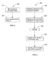
- a process 500 of fabricating the multilayer component 100 includes applying one or more layers to the foil surface layer 106 (step 501) and applying the channel-forming material 108 to at least partially define the channel 112 between the foil surface layer 106 and the substrate 110 (step 503) and then brazing them together.
- the foil surface layer 106 and the channel-forming material 108 are applied to the substrate 110 by concurrently brazing.
- the applying of the channel-forming material 108 to at least partially define the channel 112 between the foil surface layer 106 and the substrate 110 includes the channel-forming material 108 being positioned on the substrate 110 (step 602). Then, the foil surface layer 106 is positioned on the channel-forming material (step 604). Next, the channel-forming material 108 and the foil surface layer 106 are brazed to the substrate (step 606).
- the bond coat layer 104 is applied to the foil surface layer 106 (step 608), then the ceramic coating layer 102 is applied to the bond coat layer 104 (step 610). The bond coat layer 104 and/or the ceramic coating layer 102 are applied before or after the brazing of the foil surface layer and the channel-forming material 108 (step 606).
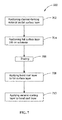
- the applying of the channel-forming material 108 to at least partially define the channel 112 between the foil surface layer 106 and the substrate 110 includes the channel-forming material 108 being positioned on the foil surface layer (step 702). Then, the foil surface layer 106 is positioned on the substrate (step 704). Next, the channel-forming material 108 and the foil surface layer 106 are brazed to the substrate (step 706).
- the bond coat layer 104 is applied to the foil surface layer 106 (step 708), then the ceramic coating layer 102 is applied to the bond coat layer 104 (step 710). The bond coat layer 104 and/or the ceramic coating layer 102 are applied before or after the brazing of the foil surface layer and the channel-forming material 108 (step 706).
- the bond coat layer 104 abuts the foil surface layer 106 and the ceramic coating layer 102. Additionally or alternatively, the bond coat layer 104 has a thermal conductivity that is less than the foil surface layer 106.
- the ceramic coating layer 102 abuts the bond coat layer 104 and is exposed to the environment of the multilayer component 100, such as, a hot gas path of a turbine.
- the ceramic coating layer 102 is any suitable thermally-resistant coating. Suitable coatings include, but are not limited to, thermal barrier coatings (TBCs) and environmental barrier coatings (EBCs).
- TBCs thermal barrier coatings
- EBCs environmental barrier coatings
- the TBC includes yttria stabilized zirconia or yttria stabilized borate. Additionally or alternatively, the TBC has a thermal conductivity that is less than the bond coat layer 104.
Landscapes
- Engineering & Computer Science (AREA)
- Mechanical Engineering (AREA)
- Chemical & Material Sciences (AREA)
- Materials Engineering (AREA)
- General Engineering & Computer Science (AREA)
- Physics & Mathematics (AREA)
- Plasma & Fusion (AREA)
- Optics & Photonics (AREA)
- Chemical Kinetics & Catalysis (AREA)
- Metallurgy (AREA)
- Organic Chemistry (AREA)
- Turbine Rotor Nozzle Sealing (AREA)
- Laminated Bodies (AREA)
- Other Surface Treatments For Metallic Materials (AREA)
Applications Claiming Priority (1)
| Application Number | Priority Date | Filing Date | Title |
|---|---|---|---|
| US13/754,281 US20140212628A1 (en) | 2013-01-30 | 2013-01-30 | Multilayer component and fabrication process |
Publications (1)
| Publication Number | Publication Date |
|---|---|
| EP2762680A1 true EP2762680A1 (de) | 2014-08-06 |
Family
ID=50000915
Family Applications (1)
| Application Number | Title | Priority Date | Filing Date |
|---|---|---|---|
| EP14153008.9A Withdrawn EP2762680A1 (de) | 2013-01-30 | 2014-01-29 | Mehrschichtelement und zugehöriges Verfahren |
Country Status (4)
| Country | Link |
|---|---|
| US (2) | US20140212628A1 (de) |
| EP (1) | EP2762680A1 (de) |
| JP (1) | JP2014148167A (de) |
| CN (1) | CN103967532A (de) |
Families Citing this family (7)
| Publication number | Priority date | Publication date | Assignee | Title |
|---|---|---|---|---|
| US20140170433A1 (en) * | 2012-12-19 | 2014-06-19 | General Electric Company | Components with near-surface cooling microchannels and methods for providing the same |
| EP2910765B1 (de) * | 2014-02-21 | 2017-10-25 | Rolls-Royce Corporation | Einphasige mikro-/minikanalwärmetauscher für die gasturbinen-zwischenkühlung und korrespondierende methode |
| EP2910887B1 (de) | 2014-02-21 | 2019-06-26 | Rolls-Royce Corporation | Mikrokanalwärmetauscher für gasturbinenzwischenkühlung und kondensation sowie korrespondierende methode |
| US9970302B2 (en) * | 2015-06-15 | 2018-05-15 | General Electric Company | Hot gas path component trailing edge having near wall cooling features |
| US10519780B2 (en) * | 2016-09-13 | 2019-12-31 | Rolls-Royce Corporation | Dual-walled components for a gas turbine engine |
| US10619499B2 (en) * | 2017-01-23 | 2020-04-14 | General Electric Company | Component and method for forming a component |
| CN111321405A (zh) * | 2018-12-15 | 2020-06-23 | 兰州交通大学 | 一种航空发动机机匣阻燃涂层电火花多点并行沉积机构 |
Citations (5)
| Publication number | Priority date | Publication date | Assignee | Title |
|---|---|---|---|---|
| US20030026697A1 (en) * | 2001-08-02 | 2003-02-06 | Siemens Westinghouse Power Corporation | Cooling structure and method of manufacturing the same |
| US6617003B1 (en) * | 2000-11-06 | 2003-09-09 | General Electric Company | Directly cooled thermal barrier coating system |
| US20030209589A1 (en) * | 2002-05-07 | 2003-11-13 | General Electric Company | Method of forming a channel on the surface of a metal substrate, and related articles |
| US20080298975A1 (en) * | 2007-05-29 | 2008-12-04 | Siemens Power Generation, Inc. | Turbine airfoils with near surface cooling passages and method of making same |
| EP2578720A2 (de) * | 2011-10-06 | 2013-04-10 | General Electric Company | Reparaturverfahren für gekühlte Komponenten |
Family Cites Families (8)
| Publication number | Priority date | Publication date | Assignee | Title |
|---|---|---|---|---|
| US5102031A (en) * | 1991-03-11 | 1992-04-07 | General Motors Corporation | Method for depositing braze alloy to base metal surfaces using electric discharge process |
| US5395584A (en) * | 1992-06-17 | 1995-03-07 | Avco Corporation | Nickel-base superalloy compositions |
| US5783318A (en) * | 1994-06-22 | 1998-07-21 | United Technologies Corporation | Repaired nickel based superalloy |
| CA2307471A1 (en) * | 1997-10-27 | 1999-05-06 | Siemens Westinghouse Power Corporation | Method of bonding cast superalloys |
| US7140952B1 (en) * | 2005-09-22 | 2006-11-28 | Pratt & Whitney Canada Corp. | Oxidation protected blade and method of manufacturing |
| US8342386B2 (en) * | 2006-12-15 | 2013-01-01 | General Electric Company | Braze materials and processes therefor |
| US8573949B2 (en) * | 2009-09-30 | 2013-11-05 | General Electric Company | Method and system for focused energy brazing |
| US20120148769A1 (en) * | 2010-12-13 | 2012-06-14 | General Electric Company | Method of fabricating a component using a two-layer structural coating |
-
2013
- 2013-01-30 US US13/754,281 patent/US20140212628A1/en not_active Abandoned
-
2014
- 2014-01-24 CN CN201410034011.1A patent/CN103967532A/zh active Pending
- 2014-01-29 JP JP2014013857A patent/JP2014148167A/ja active Pending
- 2014-01-29 EP EP14153008.9A patent/EP2762680A1/de not_active Withdrawn
-
2016
- 2016-05-03 US US15/145,454 patent/US20160243639A1/en not_active Abandoned
Patent Citations (5)
| Publication number | Priority date | Publication date | Assignee | Title |
|---|---|---|---|---|
| US6617003B1 (en) * | 2000-11-06 | 2003-09-09 | General Electric Company | Directly cooled thermal barrier coating system |
| US20030026697A1 (en) * | 2001-08-02 | 2003-02-06 | Siemens Westinghouse Power Corporation | Cooling structure and method of manufacturing the same |
| US20030209589A1 (en) * | 2002-05-07 | 2003-11-13 | General Electric Company | Method of forming a channel on the surface of a metal substrate, and related articles |
| US20080298975A1 (en) * | 2007-05-29 | 2008-12-04 | Siemens Power Generation, Inc. | Turbine airfoils with near surface cooling passages and method of making same |
| EP2578720A2 (de) * | 2011-10-06 | 2013-04-10 | General Electric Company | Reparaturverfahren für gekühlte Komponenten |
Also Published As
| Publication number | Publication date |
|---|---|
| US20140212628A1 (en) | 2014-07-31 |
| JP2014148167A (ja) | 2014-08-21 |
| CN103967532A (zh) | 2014-08-06 |
| US20160243639A1 (en) | 2016-08-25 |
Similar Documents
| Publication | Publication Date | Title |
|---|---|---|
| US20160243639A1 (en) | Process for fabricating multilayer component | |
| US8753071B2 (en) | Cooling channel systems for high-temperature components covered by coatings, and related processes | |
| US8528208B2 (en) | Methods of fabricating a coated component using multiple types of fillers | |
| CN102536465B (zh) | 使用短效涂层制作构件的方法 | |
| US8910379B2 (en) | Wireless component and methods of fabricating a coated component using multiple types of fillers | |
| CN102560481B (zh) | 使用两层式结构涂层来制造构件的方法 | |
| US9796048B2 (en) | Article and process for producing an article | |
| US9476306B2 (en) | Components with multi-layered cooling features and methods of manufacture | |
| US9567664B2 (en) | Ceramic thermal barrier coating system with two ceramic layers | |
| EP3112594A1 (de) | Heissgaspfadkomponentenhinterkante mit kühlfunktionen in wandnähe | |
| CN103796828B (zh) | 具有双层的MCrAlX金属层的层系统 | |
| US20120243995A1 (en) | Components with cooling channels formed in coating and methods of manufacture | |
| JP2012127347A (ja) | 表面近傍冷却通路を備えたタービン部品及びその方法 | |
| EP2336494A2 (de) | Turbinenschaufel | |
| US20170252870A1 (en) | Brazing tape or preform for microchannels in a thermal barrier coating | |
| US20140102684A1 (en) | Hot gas path component cooling film hole plateau | |
| US9803939B2 (en) | Methods for the formation and shaping of cooling channels, and related articles of manufacture | |
| US11555419B2 (en) | Cost effective manufacturing method for GSAC incorporating a stamped preform | |
| EP3039167B1 (de) | Thermisches sprühbeschichtungsverfahren und thermischer sprühbeschichteter artikel | |
| EP3071732B1 (de) | Artikel mit beschichtung mit veränderlicher zusammensetzung | |
| CN103649372B (zh) | 具有双层的金属层的层系统 |
Legal Events
| Date | Code | Title | Description |
|---|---|---|---|
| PUAI | Public reference made under article 153(3) epc to a published international application that has entered the european phase |
Free format text: ORIGINAL CODE: 0009012 |
|
| 17P | Request for examination filed |
Effective date: 20140129 |
|
| AK | Designated contracting states |
Kind code of ref document: A1 Designated state(s): AL AT BE BG CH CY CZ DE DK EE ES FI FR GB GR HR HU IE IS IT LI LT LU LV MC MK MT NL NO PL PT RO RS SE SI SK SM TR |
|
| AX | Request for extension of the european patent |
Extension state: BA ME |
|
| R17P | Request for examination filed (corrected) |
Effective date: 20150206 |
|
| RBV | Designated contracting states (corrected) |
Designated state(s): AL AT BE BG CH CY CZ DE DK EE ES FI FR GB GR HR HU IE IS IT LI LT LU LV MC MK MT NL NO PL PT RO RS SE SI SK SM TR |
|
| 17Q | First examination report despatched |
Effective date: 20160913 |
|
| STAA | Information on the status of an ep patent application or granted ep patent |
Free format text: STATUS: THE APPLICATION IS DEEMED TO BE WITHDRAWN |
|
| 18D | Application deemed to be withdrawn |
Effective date: 20180801 |