EP2762732A1 - Ergots de retenue - Google Patents
Ergots de retenue Download PDFInfo
- Publication number
- EP2762732A1 EP2762732A1 EP14152571.7A EP14152571A EP2762732A1 EP 2762732 A1 EP2762732 A1 EP 2762732A1 EP 14152571 A EP14152571 A EP 14152571A EP 2762732 A1 EP2762732 A1 EP 2762732A1
- Authority
- EP
- European Patent Office
- Prior art keywords
- cage
- housing
- retaining cam
- components
- projection
- Prior art date
- Legal status (The legal status is an assumption and is not a legal conclusion. Google has not performed a legal analysis and makes no representation as to the accuracy of the status listed.)
- Granted
Links
Images


Classifications
-
- F—MECHANICAL ENGINEERING; LIGHTING; HEATING; WEAPONS; BLASTING
- F16—ENGINEERING ELEMENTS AND UNITS; GENERAL MEASURES FOR PRODUCING AND MAINTAINING EFFECTIVE FUNCTIONING OF MACHINES OR INSTALLATIONS; THERMAL INSULATION IN GENERAL
- F16B—DEVICES FOR FASTENING OR SECURING CONSTRUCTIONAL ELEMENTS OR MACHINE PARTS TOGETHER, e.g. NAILS, BOLTS, CIRCLIPS, CLAMPS, CLIPS OR WEDGES; JOINTS OR JOINTING
- F16B37/00—Nuts or like thread-engaging members
- F16B37/04—Devices for fastening nuts to surfaces, e.g. sheets, plates
- F16B37/044—Nut cages
-
- F—MECHANICAL ENGINEERING; LIGHTING; HEATING; WEAPONS; BLASTING
- F16—ENGINEERING ELEMENTS AND UNITS; GENERAL MEASURES FOR PRODUCING AND MAINTAINING EFFECTIVE FUNCTIONING OF MACHINES OR INSTALLATIONS; THERMAL INSULATION IN GENERAL
- F16B—DEVICES FOR FASTENING OR SECURING CONSTRUCTIONAL ELEMENTS OR MACHINE PARTS TOGETHER, e.g. NAILS, BOLTS, CIRCLIPS, CLAMPS, CLIPS OR WEDGES; JOINTS OR JOINTING
- F16B5/00—Joining sheets or plates, e.g. panels, to one another or to strips or bars parallel to them
- F16B5/02—Joining sheets or plates, e.g. panels, to one another or to strips or bars parallel to them by means of fastening members using screw-thread
- F16B5/025—Joining sheets or plates, e.g. panels, to one another or to strips or bars parallel to them by means of fastening members using screw-thread specially designed to compensate for misalignement or to eliminate unwanted play
Definitions
- the invention relates to a retaining cam, which is suitable for a quick release for connecting, for example, plate-shaped components.
- a retaining cam has a cage which is rigidly connected to one of the components, and a housing mounted on the cage, in which a retaining cam screw is provided non-rotatably. On this a connectable with another component closure bolt with an internal thread can be screwed.
- Quick-release fasteners the basic structure of the DE 103 19 930 B4 are known to be used in aerospace to connect components made of composite materials or aluminum components quickly and captively with each other. For this purpose, it may also be necessary to be able to compensate for an axial offset of the openings of the components with the retaining cam.
- This so-called "floating" is achieved by the usually consisting of a metallic material cage accommodates the housing of the retaining cam so that the housing can move slightly relative to the cage.
- the cage has the task of attaching the housing of the retaining cam to the component so that it is held captive. If the connection between the typically plate-shaped components is made, the housing is clamped with the recorded therein camshaft bolt via the connection with the locking pin firmly with the two components.
- the known cages are made in one or more parts and are connected depending on the application with a corresponding joining technique with the housing of the retaining cam. Due to the metallic materials used, the joining effort can be relatively high. In addition, depending on the location of use, corrosion and / or contact corrosion can occur. This is undesirable.
- the object of the present invention is to provide a retaining cam which is easier to assemble and less susceptible to corrosion. It is a further object of the present invention to further improve the weight of the cradle typically used in the aerospace industry.
- the invention is based on the idea that the housing of the retaining cam (as before) consists of metal, while the cage is made of plastic. This is advantageous for a simplified joining process and simultaneously counteracts corrosion or contact corrosion. Due to the plastic design of the cage over the previously known cages made of metal weight can be saved in addition.
- the cage is designed so that the housing of the retaining cam is connected captive with the cage after joining.
- the cage should be designed so that in the mounted state, the force that is applied in the axial direction of the retaining cam screw and the locking pin, can flow without interruption of the components on the cage to the bearing surface of the housing of the retaining cam.
- the housing of the retaining cam is displaceable relative to the cage in a direction parallel to the plane of the bearing surface of the components. This allows so-called floating, ie a subsequent change in the position of the housing and thus the retaining cam screw relative to the component to which the retaining cam is attached. In this way it is possible that at the connection the locking cam screw with the locking pin small tolerances or offset can be compensated.
- the cage usually has a central opening through which the retaining cam screw and / or the locking bolt can pass.
- openings for receiving a rivet, screw or clamp connection can be provided.
- an adhesive layer for example a double-sided adhesive tape, may be provided on the side of the cage facing the components to be joined.
- Such a Kunststoffniet preferably has a head for connection to one of the components and a pin portion which is fastened in an opening of the cage by means of a latching or clamping connection.
- a plastic rivet offers the advantage of further weight savings compared to a metal rivet.
- the joining process is considerably simplified since the plastic rivet only has to be inserted without beading being required.
- a Kunststoffniet is removable and with sufficient length of the pin also thickness tolerant, so that any variations in the thickness of the plates to be joined are not relevant. The latter advantage also applies to the use of the dome, which are inserted into the corresponding openings of the plate.
- the housing has on the side facing the components to be connected at least one flange or a e.g. collar-like projection on.
- the cage may have on the side facing the components to be joined an opening for receiving the housing and on the side facing away from the components to be joined at least one bottom portion or projection for supporting the flange or projection of the housing. In this way it is possible to insert the housing from the side facing the components to be connected in the cage.
- the cage is preferably associated with a cover which is arranged on the side facing the components to be joined.
- the cover may be a separate component or integrally formed with the cage, for example connected via a film hinge.
- the lid is supported in its mounted state on a shoulder of the cage.
- the lid may be made of metal.
- the lid can for example be used with a press fit in the cage and positioned against the shoulder as a contact surface.
- the opening for receiving the housing is usually larger than the diameter of the usually cylindrical housing in order to ensure the radial mobility for tolerance compensation.
- the housing on the side facing the components to be joined a flange or a collar-like projection
- the cage has a base plate with an opening for the passage of the locking bolt and / or the retaining cam screw, and wherein on the side facing the components to be connected to the base plate at least one mounting rail or a groove for receiving the flange or collar-like projection of the housing is provided.
- the housing of the retaining cam can be laterally inserted into the rails or grooves of the cage, so that the mounting direction is substantially parallel to the plane of the components to be connected.
- the cage on the base plate has a latching projection for attachment of the housing. In this way, the housing can be captively secured in the cage without a relative movement between the housing and the cage is completely prevented.
- two mutually opposite mounting rails or grooves for receiving the flange or the example collar-like projection of the housing are provided on the components facing away from the components, the distance between the rails or grooves on the dimensions of the flange or projection of the housing are matched, that the flange or projection in the mounting rails or grooves can be pivoted and / or latched.
- the attachment of the housing thus takes place from the side of the cage facing away from the components to be connected, wherein the housing is first inserted with the flange or projection in one of the rails or grooves and then pivoted or engaged in the other rail or groove.
- the housing can be replaced without disassembly and without damaging the cage if necessary, which is not possible without destruction in the previously known metallic variants.
- the retaining cam screw can be assigned a rotation with a spring element.
- the structure of this anti-rotation can, for example, similar as in the DE 103 19 930 B4 described described.
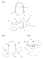
- a holding cam 1 which has a housing 2, a retaining cam screw 3 received therein, a cage 4 and a cover 5.
- plate-shaped components of the retaining cam 1 may additionally have a closure pin, as in the DE 103 19 903 B4 may be formed described.
- the retaining cam screw 3 is rotatably received in the pot-like housing 2 and can be connected to a closure pin which is at least hollow with an internal thread.
- the retaining cam screw 3 has an external thread.
- Fig. 7 shows two plate-shaped components 10, which are connectable via a retaining cam 1 with a retaining cam screw 3 and a closure pin 26.
- a flange 6 and a collar is provided, with which the housing 2 can be secured in the cage 4.
- the cage on its in the installed state facing the components to be joined side (upper side in Fig. 1 )
- On the opposite side of the opening 7 of the cage 4 is provided with two bottom portions 8, on which the flange 6 of the housing 2 is supported.
- the receptacle formed by the opening 7 in the illustrated embodiment is slightly larger than the flange 6, so that the housing 2 is accommodated with play in the cage 4.
- the lid 5 can be inserted into the cage with a press fit, wherein the lid can be flush with the cage 4, for example.
- the in Fig. 5 indicated thickness Y of the lid 5 regardless of the thickness X of the mounting area for the cage 4.
- Fig. 6 it can be seen how the lid 5 is supported on a shoulder 9 of the cage 4.
- the housing 2 rests with its flange 6 directly on the cover 5, so that the cage 4 only serves to hold the housing 2 captive on a component, However, without lying in the connection of two components in the power flow of the retaining cam 1.
- FIG. 7 shows the conventional attachment of the cage 4 by means of two metal rivets 11, the openings 12 of the cage 4 and corresponding openings 13 of the plate-shaped member 10 prevail. Additionally are in Fig. 7 also a second (upper) plate 10 and a closure pin 26 are shown. As well as in Fig. 4 For this purpose, a recess 14 or a radius can be provided on the cage 4, which serves to receive the rivet head.
- a metal rivet 11 is provided for fastening the retaining cam 1 to the component 10. This involves a significant saving in assembly time in attaching the retaining cam to the component.
- a dome 15 is formed, ie a projection which engages in one of the openings 13 in the component 10.
- the cage 4 is again provided with two openings 12, in each of which a Kunststoffniet 16 can be introduced.
- the plastic rivet is fastened by means of a latching or press fit in the openings 12 of the cage.
- the cage 4 is provided only with the central opening 7, wherein instead of lateral openings 12, two dome 15 are provided, which are inserted into the openings 13 of the component 10.
- the connection of the cage 4 with the component 10 is then carried out via a bond, for example by means of a double-sided adhesive tape, so that the dome 15 serve only for torque support.
- the dome are introduced with a press fit into the openings 13 of the component 10 in order to clamp the cage 4 on the component 10.
- the dome 15 can, when they are inserted into the openings 13, compensate for any thickness tolerances of the component 10 by their length.
- FIGS. 11 and 12 show a modification to that in the Fig. 1 to 7 shown first embodiment, wherein the lid 5 is not formed as a separate component to the cage 4, but is fastened by means of a film hinge 17 to the cage.
- the assembly of the housing 2 in the cage 4 is then similar to the above with respect to the first embodiment explained by the lid 5 is fixed after insertion of the housing 2 with a press fit in the cage 4.
- FIGS. 13 and 14 The embodiments and variants according to Fig. 1 to 12 are each designed so that the housing 2 is inserted in the figures from above, ie from the side of the component 10 ago in the cage. Alternatively, it is also possible to insert the housing 2 laterally, ie substantially parallel to the plane predetermined by the component 10, into the cage. This is in the embodiment of FIGS. 13 and 14 shown.
- the housing 2 with the retaining cam screw 3 and the flange 6 is formed as described above.
- the cage 18 has a base plate 19, in which a central opening 20 for carrying out the retaining cam screw 3 and / or the locking bolt is provided.
- two openings 12 similar to the embodiment of FIG Fig. 1 intended.
- the cage with respect to the attachment to the component 10 for example, as in the Fig. 8 to 10 be formed represented.
- On the facing away from the components to be fastened, in Fig. 13 bottom side of the cage 18 is provided with two mounting rails 21. These are on the in Fig. 13 front side open and provided with chamfers, while they are closed on the opposite side by a web 22.
- a locking projection 23 is provided in the illustrated embodiment.
- the defined by the rails 21, the web 22 and the locking projection 23 for receiving the flange 6 of the housing 2 is in turn larger than the dimensions of the flange selected, so that a relative movement of the housing to the cage 18 is possible.
- a modification of the embodiment according to the FIGS. 13 and 14 is in the 15 to 17 shown.
- these are as in Fig. 15 shown closed on both sides by webs 22.
- the distance and the contour of the mounting rails 21 are chosen so that the flange 6 of the housing 2 can be used in an inclined position of the housing 2 in one of the two rails 21 first.
- the assembly of the housing 2 in the cage 18 thus takes place substantially from the bottom, ie from the side facing away from the components 10 to be fastened.
- FIG. 17 As from the representation of Fig. 17 can be seen, 18 additional recesses 24 may be provided in the cage in order to achieve a further weight saving.
- An annular region 25 is in the embodiment according to Fig. 17 between the two recesses 24 and the central opening 20 so that the housing 2 is held captive.
- the flange 6 of the housing 2 is supported on the annular region 25 such that after the connection of the retaining cam screw with a closure bolt the housing 2 is pressed against the component 10 via the annular region 25.
Landscapes
- Engineering & Computer Science (AREA)
- General Engineering & Computer Science (AREA)
- Mechanical Engineering (AREA)
- Furniture Connections (AREA)
- Connection Of Plates (AREA)
Applications Claiming Priority (1)
| Application Number | Priority Date | Filing Date | Title |
|---|---|---|---|
| DE201320001061 DE202013001061U1 (de) | 2013-02-04 | 2013-02-04 | Haltenocken |
Publications (2)
| Publication Number | Publication Date |
|---|---|
| EP2762732A1 true EP2762732A1 (fr) | 2014-08-06 |
| EP2762732B1 EP2762732B1 (fr) | 2016-07-27 |
Family
ID=48051709
Family Applications (1)
| Application Number | Title | Priority Date | Filing Date |
|---|---|---|---|
| EP14152571.7A Active EP2762732B1 (fr) | 2013-02-04 | 2014-01-25 | Ergots de retenue |
Country Status (2)
| Country | Link |
|---|---|
| EP (1) | EP2762732B1 (fr) |
| DE (1) | DE202013001061U1 (fr) |
Cited By (1)
| Publication number | Priority date | Publication date | Assignee | Title |
|---|---|---|---|---|
| EP3708854A1 (fr) * | 2019-03-15 | 2020-09-16 | Magnesium Products of America, Inc. | Compensateur de tolérance |
Families Citing this family (2)
| Publication number | Priority date | Publication date | Assignee | Title |
|---|---|---|---|---|
| DE102016105794A1 (de) * | 2016-03-30 | 2017-10-05 | Böllhoff Verbindungstechnik GmbH | Befestigungselement |
| DE202017101870U1 (de) | 2017-03-30 | 2017-04-26 | Fairchild Fasteners Europe - Camloc Gmbh | Haltenocken und Schnellverschlusssystem hiermit |
Citations (6)
| Publication number | Priority date | Publication date | Assignee | Title |
|---|---|---|---|---|
| DE1400774A1 (de) * | 1961-06-12 | 1968-12-12 | Rex Chainbelt Inc | Schraubverbindung |
| DE60307124T2 (de) * | 2002-08-14 | 2006-12-07 | Physical Systems, Inc., Carson City | Selbstfixierende klebstoffbefestigung |
| DE10319903B4 (de) | 2003-04-29 | 2007-05-31 | Siemens Ag | Eigensichere Rechneranordnung |
| DE10319930B4 (de) | 2003-05-02 | 2007-06-21 | Fairchild Fasteners Europe - Camloc Gmbh | Verschlusseinrichtung zum Verbinden zweier Bauteile |
| WO2008157265A1 (fr) * | 2007-06-13 | 2008-12-24 | The Monadnock Company | Appareil et procédés de fixation d'une attache |
| DE202011106725U1 (de) * | 2011-09-15 | 2012-03-08 | Fairchild Fasteners Europe - Camloc Gmbh | Haltenocken |
-
2013
- 2013-02-04 DE DE201320001061 patent/DE202013001061U1/de not_active Expired - Lifetime
-
2014
- 2014-01-25 EP EP14152571.7A patent/EP2762732B1/fr active Active
Patent Citations (6)
| Publication number | Priority date | Publication date | Assignee | Title |
|---|---|---|---|---|
| DE1400774A1 (de) * | 1961-06-12 | 1968-12-12 | Rex Chainbelt Inc | Schraubverbindung |
| DE60307124T2 (de) * | 2002-08-14 | 2006-12-07 | Physical Systems, Inc., Carson City | Selbstfixierende klebstoffbefestigung |
| DE10319903B4 (de) | 2003-04-29 | 2007-05-31 | Siemens Ag | Eigensichere Rechneranordnung |
| DE10319930B4 (de) | 2003-05-02 | 2007-06-21 | Fairchild Fasteners Europe - Camloc Gmbh | Verschlusseinrichtung zum Verbinden zweier Bauteile |
| WO2008157265A1 (fr) * | 2007-06-13 | 2008-12-24 | The Monadnock Company | Appareil et procédés de fixation d'une attache |
| DE202011106725U1 (de) * | 2011-09-15 | 2012-03-08 | Fairchild Fasteners Europe - Camloc Gmbh | Haltenocken |
Cited By (3)
| Publication number | Priority date | Publication date | Assignee | Title |
|---|---|---|---|---|
| EP3708854A1 (fr) * | 2019-03-15 | 2020-09-16 | Magnesium Products of America, Inc. | Compensateur de tolérance |
| CN111692184A (zh) * | 2019-03-15 | 2020-09-22 | 美国镁产品有限公司 | 公差补偿器 |
| US11542976B2 (en) | 2019-03-15 | 2023-01-03 | Magnesium Products of America Inc. | Tolerance compensator |
Also Published As
| Publication number | Publication date |
|---|---|
| EP2762732B1 (fr) | 2016-07-27 |
| DE202013001061U1 (de) | 2013-03-04 |
Similar Documents
| Publication | Publication Date | Title |
|---|---|---|
| EP2720907B1 (fr) | Dispositif de fixation comprenant un compensateur de tolérance | |
| EP2834527B1 (fr) | Système de fixation à compensation de tolérances et procédé de prémontage et montage | |
| EP1979634B1 (fr) | Unité de montage destinée à un anneau de fixation d'une boucle de ceinture | |
| EP3602708B1 (fr) | Ossature d'armoire électrique avec socle | |
| EP2495453A2 (fr) | Dispositif de fixation doté d'une égalisation de tolérance | |
| WO2019120665A1 (fr) | Dispositif de compensation de tolérance avec sécurité par serrage | |
| DE102015122744A1 (de) | Verstellbare Distanzhülse | |
| EP2762732B1 (fr) | Ergots de retenue | |
| DE102013200999A1 (de) | Toleranzausgleichsvorrichtung | |
| DE102008062457B4 (de) | Befestigungsanordnung, Befestigungselement und Verfahren zur Befestigung dieser | |
| EP2118416A1 (fr) | Dispositif comprenant un insert de montage pour la fixation de ferrures sur des profilés creux ainsi que procédé pour la pose de l'insert de montage sur le profilé creux | |
| DE102014113126A1 (de) | Toleranzausgleichsvorrichtung | |
| WO2013153091A1 (fr) | Support de toit pour un porte-bagages de toit pouvant être fixé sur celui-ci | |
| EP1809912B1 (fr) | Systeme de fixation notamment destine a un echangeur thermique | |
| EP2245412B1 (fr) | Dispositif de fixation d'un élément auxiliaire, notamment d'un viseur, sur une arme | |
| EP2570681B1 (fr) | Taquets de retenue | |
| EP1612432B1 (fr) | Dispositif de fixation pour habillage et méthode de fixation | |
| EP3884172B1 (fr) | Came de maintien et système de fermeture rapide équipé de celle-ci | |
| DE102018107083A1 (de) | Befestigungseinrichtung und Verfahren zur Befestigung eines Anbauteils an einem Tragteil, Bauteilsystem und Kraftfahrzeug | |
| DE202012104557U1 (de) | Mitnehmer | |
| DE202014100687U1 (de) | Als Wendescharnier ausgebildetes Kraftfahrzeugtürscharnier | |
| DE102017219753A1 (de) | Radlagergehäuse mit einem Radlager | |
| EP2150726B1 (fr) | Dispositif tendeur à excentrique | |
| DE102007003559B4 (de) | Befestigungsanordnung | |
| DE102016214938A1 (de) | Steckmutter |
Legal Events
| Date | Code | Title | Description |
|---|---|---|---|
| PUAI | Public reference made under article 153(3) epc to a published international application that has entered the european phase |
Free format text: ORIGINAL CODE: 0009012 |
|
| 17P | Request for examination filed |
Effective date: 20140125 |
|
| AK | Designated contracting states |
Kind code of ref document: A1 Designated state(s): AL AT BE BG CH CY CZ DE DK EE ES FI FR GB GR HR HU IE IS IT LI LT LU LV MC MK MT NL NO PL PT RO RS SE SI SK SM TR |
|
| AX | Request for extension of the european patent |
Extension state: BA ME |
|
| R17P | Request for examination filed (corrected) |
Effective date: 20150204 |
|
| RBV | Designated contracting states (corrected) |
Designated state(s): AL AT BE BG CH CY CZ DE DK EE ES FI FR GB GR HR HU IE IS IT LI LT LU LV MC MK MT NL NO PL PT RO RS SE SI SK SM TR |
|
| GRAP | Despatch of communication of intention to grant a patent |
Free format text: ORIGINAL CODE: EPIDOSNIGR1 |
|
| INTG | Intention to grant announced |
Effective date: 20160329 |
|
| GRAS | Grant fee paid |
Free format text: ORIGINAL CODE: EPIDOSNIGR3 |
|
| GRAA | (expected) grant |
Free format text: ORIGINAL CODE: 0009210 |
|
| AK | Designated contracting states |
Kind code of ref document: B1 Designated state(s): AL AT BE BG CH CY CZ DE DK EE ES FI FR GB GR HR HU IE IS IT LI LT LU LV MC MK MT NL NO PL PT RO RS SE SI SK SM TR |
|
| REG | Reference to a national code |
Ref country code: GB Ref legal event code: FG4D Free format text: NOT ENGLISH |
|
| REG | Reference to a national code |
Ref country code: CH Ref legal event code: EP |
|
| REG | Reference to a national code |
Ref country code: AT Ref legal event code: REF Ref document number: 816058 Country of ref document: AT Kind code of ref document: T Effective date: 20160815 |
|
| REG | Reference to a national code |
Ref country code: IE Ref legal event code: FG4D Free format text: LANGUAGE OF EP DOCUMENT: GERMAN |
|
| REG | Reference to a national code |
Ref country code: DE Ref legal event code: R096 Ref document number: 502014001170 Country of ref document: DE |
|
| REG | Reference to a national code |
Ref country code: LT Ref legal event code: MG4D |
|
| REG | Reference to a national code |
Ref country code: NL Ref legal event code: MP Effective date: 20160727 |
|
| REG | Reference to a national code |
Ref country code: FR Ref legal event code: PLFP Year of fee payment: 4 |
|
| PG25 | Lapsed in a contracting state [announced via postgrant information from national office to epo] |
Ref country code: HR Free format text: LAPSE BECAUSE OF FAILURE TO SUBMIT A TRANSLATION OF THE DESCRIPTION OR TO PAY THE FEE WITHIN THE PRESCRIBED TIME-LIMIT Effective date: 20160727 Ref country code: FI Free format text: LAPSE BECAUSE OF FAILURE TO SUBMIT A TRANSLATION OF THE DESCRIPTION OR TO PAY THE FEE WITHIN THE PRESCRIBED TIME-LIMIT Effective date: 20160727 Ref country code: NO Free format text: LAPSE BECAUSE OF FAILURE TO SUBMIT A TRANSLATION OF THE DESCRIPTION OR TO PAY THE FEE WITHIN THE PRESCRIBED TIME-LIMIT Effective date: 20161027 Ref country code: IT Free format text: LAPSE BECAUSE OF FAILURE TO SUBMIT A TRANSLATION OF THE DESCRIPTION OR TO PAY THE FEE WITHIN THE PRESCRIBED TIME-LIMIT Effective date: 20160727 Ref country code: IS Free format text: LAPSE BECAUSE OF FAILURE TO SUBMIT A TRANSLATION OF THE DESCRIPTION OR TO PAY THE FEE WITHIN THE PRESCRIBED TIME-LIMIT Effective date: 20161127 Ref country code: LT Free format text: LAPSE BECAUSE OF FAILURE TO SUBMIT A TRANSLATION OF THE DESCRIPTION OR TO PAY THE FEE WITHIN THE PRESCRIBED TIME-LIMIT Effective date: 20160727 Ref country code: NL Free format text: LAPSE BECAUSE OF FAILURE TO SUBMIT A TRANSLATION OF THE DESCRIPTION OR TO PAY THE FEE WITHIN THE PRESCRIBED TIME-LIMIT Effective date: 20160727 Ref country code: RS Free format text: LAPSE BECAUSE OF FAILURE TO SUBMIT A TRANSLATION OF THE DESCRIPTION OR TO PAY THE FEE WITHIN THE PRESCRIBED TIME-LIMIT Effective date: 20160727 |
|
| PG25 | Lapsed in a contracting state [announced via postgrant information from national office to epo] |
Ref country code: LV Free format text: LAPSE BECAUSE OF FAILURE TO SUBMIT A TRANSLATION OF THE DESCRIPTION OR TO PAY THE FEE WITHIN THE PRESCRIBED TIME-LIMIT Effective date: 20160727 Ref country code: PL Free format text: LAPSE BECAUSE OF FAILURE TO SUBMIT A TRANSLATION OF THE DESCRIPTION OR TO PAY THE FEE WITHIN THE PRESCRIBED TIME-LIMIT Effective date: 20160727 Ref country code: ES Free format text: LAPSE BECAUSE OF FAILURE TO SUBMIT A TRANSLATION OF THE DESCRIPTION OR TO PAY THE FEE WITHIN THE PRESCRIBED TIME-LIMIT Effective date: 20160727 Ref country code: PT Free format text: LAPSE BECAUSE OF FAILURE TO SUBMIT A TRANSLATION OF THE DESCRIPTION OR TO PAY THE FEE WITHIN THE PRESCRIBED TIME-LIMIT Effective date: 20161128 Ref country code: GR Free format text: LAPSE BECAUSE OF FAILURE TO SUBMIT A TRANSLATION OF THE DESCRIPTION OR TO PAY THE FEE WITHIN THE PRESCRIBED TIME-LIMIT Effective date: 20161028 Ref country code: SE Free format text: LAPSE BECAUSE OF FAILURE TO SUBMIT A TRANSLATION OF THE DESCRIPTION OR TO PAY THE FEE WITHIN THE PRESCRIBED TIME-LIMIT Effective date: 20160727 |
|
| PG25 | Lapsed in a contracting state [announced via postgrant information from national office to epo] |
Ref country code: EE Free format text: LAPSE BECAUSE OF FAILURE TO SUBMIT A TRANSLATION OF THE DESCRIPTION OR TO PAY THE FEE WITHIN THE PRESCRIBED TIME-LIMIT Effective date: 20160727 Ref country code: RO Free format text: LAPSE BECAUSE OF FAILURE TO SUBMIT A TRANSLATION OF THE DESCRIPTION OR TO PAY THE FEE WITHIN THE PRESCRIBED TIME-LIMIT Effective date: 20160727 |
|
| REG | Reference to a national code |
Ref country code: DE Ref legal event code: R097 Ref document number: 502014001170 Country of ref document: DE |
|
| PG25 | Lapsed in a contracting state [announced via postgrant information from national office to epo] |
Ref country code: BE Free format text: LAPSE BECAUSE OF NON-PAYMENT OF DUE FEES Effective date: 20170131 Ref country code: DK Free format text: LAPSE BECAUSE OF FAILURE TO SUBMIT A TRANSLATION OF THE DESCRIPTION OR TO PAY THE FEE WITHIN THE PRESCRIBED TIME-LIMIT Effective date: 20160727 Ref country code: BG Free format text: LAPSE BECAUSE OF FAILURE TO SUBMIT A TRANSLATION OF THE DESCRIPTION OR TO PAY THE FEE WITHIN THE PRESCRIBED TIME-LIMIT Effective date: 20161027 Ref country code: SM Free format text: LAPSE BECAUSE OF FAILURE TO SUBMIT A TRANSLATION OF THE DESCRIPTION OR TO PAY THE FEE WITHIN THE PRESCRIBED TIME-LIMIT Effective date: 20160727 Ref country code: CZ Free format text: LAPSE BECAUSE OF FAILURE TO SUBMIT A TRANSLATION OF THE DESCRIPTION OR TO PAY THE FEE WITHIN THE PRESCRIBED TIME-LIMIT Effective date: 20160727 Ref country code: SK Free format text: LAPSE BECAUSE OF FAILURE TO SUBMIT A TRANSLATION OF THE DESCRIPTION OR TO PAY THE FEE WITHIN THE PRESCRIBED TIME-LIMIT Effective date: 20160727 |
|
| PLBE | No opposition filed within time limit |
Free format text: ORIGINAL CODE: 0009261 |
|
| STAA | Information on the status of an ep patent application or granted ep patent |
Free format text: STATUS: NO OPPOSITION FILED WITHIN TIME LIMIT |
|
| 26N | No opposition filed |
Effective date: 20170502 |
|
| PG25 | Lapsed in a contracting state [announced via postgrant information from national office to epo] |
Ref country code: SI Free format text: LAPSE BECAUSE OF FAILURE TO SUBMIT A TRANSLATION OF THE DESCRIPTION OR TO PAY THE FEE WITHIN THE PRESCRIBED TIME-LIMIT Effective date: 20160727 |
|
| REG | Reference to a national code |
Ref country code: CH Ref legal event code: PL |
|
| PG25 | Lapsed in a contracting state [announced via postgrant information from national office to epo] |
Ref country code: MC Free format text: LAPSE BECAUSE OF FAILURE TO SUBMIT A TRANSLATION OF THE DESCRIPTION OR TO PAY THE FEE WITHIN THE PRESCRIBED TIME-LIMIT Effective date: 20160727 |
|
| PG25 | Lapsed in a contracting state [announced via postgrant information from national office to epo] |
Ref country code: CH Free format text: LAPSE BECAUSE OF NON-PAYMENT OF DUE FEES Effective date: 20170131 Ref country code: LI Free format text: LAPSE BECAUSE OF NON-PAYMENT OF DUE FEES Effective date: 20170131 |
|
| REG | Reference to a national code |
Ref country code: IE Ref legal event code: MM4A |
|
| PG25 | Lapsed in a contracting state [announced via postgrant information from national office to epo] |
Ref country code: LU Free format text: LAPSE BECAUSE OF NON-PAYMENT OF DUE FEES Effective date: 20170125 |
|
| REG | Reference to a national code |
Ref country code: FR Ref legal event code: PLFP Year of fee payment: 5 |
|
| REG | Reference to a national code |
Ref country code: BE Ref legal event code: MM Effective date: 20170131 |
|
| PG25 | Lapsed in a contracting state [announced via postgrant information from national office to epo] |
Ref country code: IE Free format text: LAPSE BECAUSE OF NON-PAYMENT OF DUE FEES Effective date: 20170125 |
|
| GBPC | Gb: european patent ceased through non-payment of renewal fee |
Effective date: 20180125 |
|
| PG25 | Lapsed in a contracting state [announced via postgrant information from national office to epo] |
Ref country code: MT Free format text: LAPSE BECAUSE OF FAILURE TO SUBMIT A TRANSLATION OF THE DESCRIPTION OR TO PAY THE FEE WITHIN THE PRESCRIBED TIME-LIMIT Effective date: 20160727 |
|
| PG25 | Lapsed in a contracting state [announced via postgrant information from national office to epo] |
Ref country code: AL Free format text: LAPSE BECAUSE OF FAILURE TO SUBMIT A TRANSLATION OF THE DESCRIPTION OR TO PAY THE FEE WITHIN THE PRESCRIBED TIME-LIMIT Effective date: 20160727 |
|
| PG25 | Lapsed in a contracting state [announced via postgrant information from national office to epo] |
Ref country code: GB Free format text: LAPSE BECAUSE OF NON-PAYMENT OF DUE FEES Effective date: 20180125 |
|
| PG25 | Lapsed in a contracting state [announced via postgrant information from national office to epo] |
Ref country code: HU Free format text: LAPSE BECAUSE OF FAILURE TO SUBMIT A TRANSLATION OF THE DESCRIPTION OR TO PAY THE FEE WITHIN THE PRESCRIBED TIME-LIMIT; INVALID AB INITIO Effective date: 20140125 |
|
| PG25 | Lapsed in a contracting state [announced via postgrant information from national office to epo] |
Ref country code: CY Free format text: LAPSE BECAUSE OF NON-PAYMENT OF DUE FEES Effective date: 20160727 |
|
| PG25 | Lapsed in a contracting state [announced via postgrant information from national office to epo] |
Ref country code: MK Free format text: LAPSE BECAUSE OF FAILURE TO SUBMIT A TRANSLATION OF THE DESCRIPTION OR TO PAY THE FEE WITHIN THE PRESCRIBED TIME-LIMIT Effective date: 20160727 |
|
| REG | Reference to a national code |
Ref country code: AT Ref legal event code: MM01 Ref document number: 816058 Country of ref document: AT Kind code of ref document: T Effective date: 20190125 |
|
| PG25 | Lapsed in a contracting state [announced via postgrant information from national office to epo] |
Ref country code: TR Free format text: LAPSE BECAUSE OF FAILURE TO SUBMIT A TRANSLATION OF THE DESCRIPTION OR TO PAY THE FEE WITHIN THE PRESCRIBED TIME-LIMIT Effective date: 20160727 |
|
| PG25 | Lapsed in a contracting state [announced via postgrant information from national office to epo] |
Ref country code: AT Free format text: LAPSE BECAUSE OF NON-PAYMENT OF DUE FEES Effective date: 20190125 |
|
| PGFP | Annual fee paid to national office [announced via postgrant information from national office to epo] |
Ref country code: FR Payment date: 20251217 Year of fee payment: 13 |
|
| PGFP | Annual fee paid to national office [announced via postgrant information from national office to epo] |
Ref country code: DE Payment date: 20251217 Year of fee payment: 13 |