EP2762761A2 - Tuyau d'échappement et système de tuyau d'échappement - Google Patents
Tuyau d'échappement et système de tuyau d'échappement Download PDFInfo
- Publication number
- EP2762761A2 EP2762761A2 EP13174531.7A EP13174531A EP2762761A2 EP 2762761 A2 EP2762761 A2 EP 2762761A2 EP 13174531 A EP13174531 A EP 13174531A EP 2762761 A2 EP2762761 A2 EP 2762761A2
- Authority
- EP
- European Patent Office
- Prior art keywords
- exhaust pipe
- pipe
- section
- smooth
- exhaust
- Prior art date
- Legal status (The legal status is an assumption and is not a legal conclusion. Google has not performed a legal analysis and makes no representation as to the accuracy of the status listed.)
- Granted
Links
Images



Classifications
-
- F—MECHANICAL ENGINEERING; LIGHTING; HEATING; WEAPONS; BLASTING
- F16—ENGINEERING ELEMENTS AND UNITS; GENERAL MEASURES FOR PRODUCING AND MAINTAINING EFFECTIVE FUNCTIONING OF MACHINES OR INSTALLATIONS; THERMAL INSULATION IN GENERAL
- F16L—PIPES; JOINTS OR FITTINGS FOR PIPES; SUPPORTS FOR PIPES, CABLES OR PROTECTIVE TUBING; MEANS FOR THERMAL INSULATION IN GENERAL
- F16L37/00—Couplings of the quick-acting type
- F16L37/08—Couplings of the quick-acting type in which the connection between abutting or axially overlapping ends is maintained by locking members
- F16L37/10—Couplings of the quick-acting type in which the connection between abutting or axially overlapping ends is maintained by locking members using a rotary external sleeve or ring on one part
- F16L37/113—Couplings of the quick-acting type in which the connection between abutting or axially overlapping ends is maintained by locking members using a rotary external sleeve or ring on one part the male part having lugs on its periphery penetrating into the corresponding slots provided in the female part
-
- F—MECHANICAL ENGINEERING; LIGHTING; HEATING; WEAPONS; BLASTING
- F16—ENGINEERING ELEMENTS AND UNITS; GENERAL MEASURES FOR PRODUCING AND MAINTAINING EFFECTIVE FUNCTIONING OF MACHINES OR INSTALLATIONS; THERMAL INSULATION IN GENERAL
- F16L—PIPES; JOINTS OR FITTINGS FOR PIPES; SUPPORTS FOR PIPES, CABLES OR PROTECTIVE TUBING; MEANS FOR THERMAL INSULATION IN GENERAL
- F16L11/00—Hoses, i.e. flexible pipes
- F16L11/14—Hoses, i.e. flexible pipes made of rigid material, e.g. metal or hard plastics
- F16L11/15—Hoses, i.e. flexible pipes made of rigid material, e.g. metal or hard plastics corrugated
-
- F—MECHANICAL ENGINEERING; LIGHTING; HEATING; WEAPONS; BLASTING
- F16—ENGINEERING ELEMENTS AND UNITS; GENERAL MEASURES FOR PRODUCING AND MAINTAINING EFFECTIVE FUNCTIONING OF MACHINES OR INSTALLATIONS; THERMAL INSULATION IN GENERAL
- F16L—PIPES; JOINTS OR FITTINGS FOR PIPES; SUPPORTS FOR PIPES, CABLES OR PROTECTIVE TUBING; MEANS FOR THERMAL INSULATION IN GENERAL
- F16L25/00—Construction or details of pipe joints not provided for in, or of interest apart from, groups F16L13/00 - F16L23/00
- F16L25/0036—Joints for corrugated pipes
-
- F—MECHANICAL ENGINEERING; LIGHTING; HEATING; WEAPONS; BLASTING
- F23—COMBUSTION APPARATUS; COMBUSTION PROCESSES
- F23J—REMOVAL OR TREATMENT OF COMBUSTION PRODUCTS OR COMBUSTION RESIDUES; FLUES
- F23J13/00—Fittings for chimneys or flues
- F23J13/04—Joints; Connections
-
- F—MECHANICAL ENGINEERING; LIGHTING; HEATING; WEAPONS; BLASTING
- F23—COMBUSTION APPARATUS; COMBUSTION PROCESSES
- F23J—REMOVAL OR TREATMENT OF COMBUSTION PRODUCTS OR COMBUSTION RESIDUES; FLUES
- F23J2213/00—Chimneys or flues
- F23J2213/20—Joints; Connections
- F23J2213/202—Joints; Connections between duct or stack sections
-
- F—MECHANICAL ENGINEERING; LIGHTING; HEATING; WEAPONS; BLASTING
- F23—COMBUSTION APPARATUS; COMBUSTION PROCESSES
- F23J—REMOVAL OR TREATMENT OF COMBUSTION PRODUCTS OR COMBUSTION RESIDUES; FLUES
- F23J2213/00—Chimneys or flues
- F23J2213/30—Specific materials
- F23J2213/302—Specific materials plastic
Definitions
- the invention relates to an exhaust pipe, in particular made of plastic, preferably made of polyamide, with alternately arranged rigid, preferably cylindrical smooth tube and bendable corrugated pipe sections according to the preamble of claim 1 and an exhaust pipe system comprising such an exhaust pipe or a separated from such exhaust pipe exhaust pipe section and a Fuse element according to claim 10. Furthermore, the invention relates to a method for fixing an exhaust pipe to a pipe section according to claim 16.
- the known exhaust pipe forms a pipe string, from the exhaust pipe sections, comprising two end-side rigid smooth pipe sections and at least one bendable corrugated pipe section, for example by sawing or cutting can be separated, in particular angularly mutually arranged or parallel offset rigid pipe pieces (flexible) to connect to each other via the exhaust pipe section, in which the smooth-tube sections of the exhaust pipe or of the exhaust pipe section separated therefrom are inserted into corresponding receptacles, in particular sleeves of the staggered rigid exhaust pipes arranged offset to one another.
- the sealing of the exhaust gas flow takes place via arranged in annular grooves of the socket pipes seals.
- annular grooves of the socket pipes seals For axially securing the exhaust pipe or the exhaust pipe section with its smooth tube and corrugated pipe sections, it is known to receive in the seal receiving annular groove a spring ring which is radially inwardly supported on a smooth pipe section of the exhaust pipe and the exhaust pipe section and this fixed by clamping.
- the known exhaust pipe with its alternating rigid smooth-tube and bendable corrugated pipe sections has proven excellent in practice.
- the invention is therefore based on the object of specifying an improved with regard to its mountability, in particular axial reliability exhaust pipe, as well as an optimized this exhaust pipe system.
- the object is to provide a method for comfortable handling of an exhaust pipe designed according to the concept of the invention.
- the invention is based on the idea, on the exhaust pipe integral, ie integrally formed with the exhaust pipe securing means, ie to be formed during its manufacture, which are designed such that on this one, preferably sleeve-shaped securing element by a relative rotation to the exhaust pipe for producing a in the axial direction effective form fit can be fixed.
- the exhaust pipe formed according to the concept of the invention comprises integral securing means which allow a securing element separate from the exhaust pipe to be screwed in such that the exhaust pipe is secured or prevented from axially pulling off the securing element after this relative rotational movement.
- the exhaust pipe passes through the securing element in the axial direction.
- the exhaust pipe formed according to the concept of the invention is characterized in that without much effort, the securing means according to the invention can be formed in the production of the exhaust pipe, ie can be provided and this requires no separate production step.
- a formed according to the concept of the invention exhaust pipe is characterized by an extremely comfortable handling during axial securing, since the axial securing takes place on an adjacent pipe piece in that a securing element, which is preferably secured to the adjacent pipe section in the axial direction, by relative rotation to the exhaust pipe, more precisely to its securing means, can be fixed thereto, such that an effective positive locking in the axial direction results, ie such that the securing element with its engagement means engages behind the securing means of the exhaust pipe in the circumferential direction.
- the positive connection by corresponding rotation of the securing element, in particular against a Aufnavraum, in particular after overcoming a locking force (eg clamping force) can be released again.
- the axial securing means and / or the engagement means of the securing element are designed such that at the same time during relative rotation of the securing element relative to the exhaust pipe, an axial force component is generated, which braces the securing element and the axially preferably secured to an adjacent piece of pipe securing element axially against each other.
- This can be achieved in that the engagement means of the securing element and / or the securing means of the exhaust pipe have a pitch portion which generates the desired Axialkraftkomponente. It is particularly preferred, as will be explained later, when the securing means have locking means to secure the securing element, in particular by locking with the locking means against unintentional loosening.
- the exhaust pipe according to the invention therefore has a number of advantages over the prior art, without sacrificing the known advantages. So it is still possible and intended to separate out of a preferably designed as a pipe string exhaust pipe as long as desired pipe sections, for example by saws or cutting, comprising at least one smooth pipe section and at least a corrugated pipe section, wherein it is preferred if the separated-off exhaust pipe section has two end-side smooth pipe sections.
- the inner diameter of the smooth pipe sections is at least approximately the same size as an inner diameter of the corrugated pipe sections in the region of its wave troughs.
- the axial extension of the smooth tube sections is selected so that at an approximately central separation of a smooth tube section result in two tubes whose end, initially from a common smooth tube section resulting smooth tube sections are dimensioned so long that both can be sealingly received in each case in a socket tube with inner seal.
- the axial extent of the smooth tube sections is more than 8 cm, preferably more than 10 cm, and very particularly preferably is selected from a value range between approximately 9 cm and 15 cm.
- the smooth tube sections have a middle marking for marking the axial center, wherein it is further preferably a full-circumferential marking, for example in the form of a circumferential groove and / or radial elevation.
- the wave contour of the waves of the corrugated pipe section there are different possibilities.
- it is longitudinally a rounded wave contour, wherein it is of course also conceivable to realize an angular, for example rectangular wave contour.
- each smooth tube section is associated with at least one securing means, wherein, of course, an embodiment is assigned, in which each smooth tube section two axially spaced securing means (eg two male thread sections or two bayonet locking radial projections) are assigned to divide a smooth tube section of the tubular exhaust pipe into two independent smooth pipe sections of resulting pipe sections to be, in which case both smooth pipe sections, each with a securing element to a piece of pipe can be fixed.
- two axially spaced securing means eg two male thread sections or two bayonet locking radial projections
- the securing means by relative rotation of a fuse element in the circumferential direction can engage behind the securing means, thus achieving an axial securing.
- the securing means are preferably open or grippable on at least one side directed in the circumferential direction, so that an axial securing can be achieved by a twisting movement.
- the securing means comprise or are formed as an external thread portion for screwing with an internally threaded portion of a rotatable relative to the exhaust pipe securing element, in which case the axial securing takes place by a screwing movement. It is very particularly preferred if the male thread section comprises at least one complete thread turn.
- the securing means or the securing means are formed as part of a bayonet closure, which is completed by corresponding engagement means of the fuse element.
- the exhaust pipe bayonet locking means in particular at least two circumferentially spaced, preferably more than two, in particular evenly distributed in the circumferential direction, radial extensions, which preferably extend over a circumferential angle of at least 5 ° in the circumferential direction and can be engaged behind in the circumferential direction of the engagement means the securing element in the manner of a bayonet lock for axial securing.
- the fixation is effected by a combined axial relative movement between the securing element and the exhaust pipe and then a rotational movement of the securing element relative to the preferably then fixed exhaust pipe.
- a male threaded portion of the securing means there are again different possibilities.
- an external thread section in addition to a (in particular all) corrugated pipe section (s), in particular end side of the corrugated pipe section, in which case the corrugated pipe section preferably as in the prior art of a plurality of adjacent in the axial direction, in particular adjacent shafts is, wherein the waves do not pass each other, but as mutually separate annular grooves are formed, which are provided in axially adjacent radial planes, based on an axial extent of a rolled, elongated exhaust pipe.
- the corrugated pipe sections are each formed, in particular completely or axially continuously, by external thread sections.
- external thread which is not necessarily in runs separate radial planes, but along the axial extent of the exhaust pipe with the predetermined slope, along winds.
- the external thread runs in an axially adjacent smooth tube section, in particular in which the height (radial extent) of the thread turn of the external thread in the direction of the smooth tube section decreases slowly in the circumferential direction. In other words, the height increases in the circumferential direction of the thread turn from the smooth pipe section in the circumferential direction preferably.
- the securing means are hollow inside.
- the securing means viewed from the exhaust-gas pipe inner side, are groove-shaped or channel-shaped, in particular as a radially outward and circumferentially extending, in particular elongated recess.
- the exhaust pipe wall thickness of the securing means at least approximately corresponds to an exhaust pipe wall thickness of the smooth pipe sections and / or one of the corrugated pipe sections, wherein it is particularly preferred if the wall thickness of the exhaust pipe axially at least approximately is constant.
- the wall thickness is selected from a thickness range between about 0.8 and 2.5 mm, in particular between 1 and 2 mm. Most preferably, the wall thickness is at least approximately 1.2mm.
- the securing means are not only designed such that an axial securing can be achieved. It is particularly preferred if these, in particular are also formed by providing a corresponding recess and / or increase in such a way that the securing element can engage or spring in order to thus provide locking means which prevent unintentional loosening of the securing element in the circumferential direction.
- the invention also leads to an exhaust pipe section which is produced by separating a section of the exhaust pipe according to the invention.
- the separated exhaust pipe section comprises at least one smooth pipe and at least one corrugated pipe section and integral securing means adjacent to the at least one smooth pipe section.
- the invention leads to the use of a trained according to the concept of the invention exhaust pipe or exhaust pipe section for exhaust system of a heating system, especially in a building (real estate), most preferably a smooth pipe section of the exhaust pipe or the exhaust pipe section is inserted into a socket tube, in which an annular seal is provided, which rests sealingly outside on the smooth tube section of the exhaust pipe or exhaust pipe section.
- the securing element connects the sleeve tube with the integral securing means, in particular the thread or the bayonet of the exhaust pipe or exhaust pipe section, wherein very particularly preferably an annular bead of the sleeve pipe is overlapped axially by the securing element, wherein even more preferably the aforementioned ring seal is disposed within the annular bead.
- the invention also leads to an exhaust pipe system comprising an exhaust pipe formed as described above and / or a separate pipe section from such an exhaust pipe with at least one smooth pipe section, preferably with two end and optionally further smooth pipe sections and at least one bendable corrugated pipe section.
- the exhaust pipe system comprises a, preferably sleeve-shaped securing element with engagement means, wherein the securing element is rotatable relative to the exhaust pipe, in particular on this, to effect by means of a rotational movement in an axial direction effective positive engagement between the engagement means and the securing means of the exhaust pipe, wherein the engagement means
- the securing means engage behind in the circumferential direction and thus prevent axial withdrawal of the engagement means of the exhaust pipe.
- the exhaust pipe system in addition to the exhaust pipe and the securing element comprise at least one further piece of pipe on which the engagement means are fixed axially, in particular by radially engaging behind a Ringwulstes, thus the pipe section, which of course also serves for the passage of exhaust gas and to secure the exhaust pipe axially against each other.
- annular bead is preferably a ring seal, which rests sealingly on the outside of the smooth tubular section of the smooth tube section of the exhaust pipe or exhaust pipe section introduced into the pipe, in order to reliably prevent the escape of exhaust gas.
- axial clamping of the exhaust pipe and pipe section takes place simultaneously, wherein for this purpose preferably the engagement means of the securing element and / or the securing means of the exhaust pipe with a corresponding slope for generating an axial clamping force by relative rotation of the fuse element to the exhaust pipe to produce bwz. to effect.
- the securing element has at least one rear grip portion for engaging behind, in particular an annular bead of further preferably designed as a socket tube further tube piece, it being preferred if a plurality of such, in particular uniformly circumferentially spaced rear handle portions are provided.
- These may for example be formed like a tab, but preferably such that they can spring in the radial direction in order to push the securing element axially on the pipe piece, in particular such that an annular bead of the pipe section, which preferably in the interior of a seal for radially outer abutment Having a smooth tube section of the exhaust pipe, is engaged behind in the radial direction radially inward.
- the invention also leads to a method for determining an exhaust pipe formed according to the concept of the invention or a pipe section separated therefrom, wherein according to the invention the smooth pipe section of the exhaust pipe or the exhaust pipe section is inserted into the pipe section, in particular such that a ring seal held in an annular groove of the pipe section radially on the outside of the smooth pipe section. Thereafter, the engagement means, which are preferably traversed by the exhaust pipe section, rotated relative to the exhaust pipe, whereby an effective axial connection is made positive.
- the securing element is axially secured on the pipe section, in particular by the securing element being pushed axially onto the pipe section, such that the securing element engages inwardly around a pipe section, in particular a ring bead, in the radial direction.
- the sliding can also be done in the attachment direction of the smooth pipe section on the pipe section by the Schugreifabitese are pushed over the annular bead of the pipe section and then spring radially inward and secure the securing element in the axial direction ,
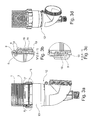
- FIGS. 1a to 1c is a section of a first embodiment of an exhaust pipe 1 shown in plastic, which was produced in the extrusion blown process.
- the exhaust pipe 1 preferably has a plurality of alternately arranged corrugated pipe sections and smooth pipe sections and even more preferably as a pipe string can be rolled up.
- the smooth pipe sections 3 are used for axial insertion into a preferably designed as a socket pipe section.
- the corrugated pipe section consists of a plurality of axially adjacent shafts 4, which, viewed from the inside, are designed as circumferentially closed annular grooves.
- the shafts 4 are located in axially parallel, parallel radial planes, i. they are formed pitch-free, as is known from corrugated pipes described in the prior art.
- the contour of the waves 4 is viewed from the outside at least approximately trapezoidal, with other contours, such as rounded contours or rectangular contours can be realized.
- the exhaust pipe 1 integral securing means 5, here in the form of circumferentially spaced and each located at the same axial height, pointing radially outward radial projections 6, which together with suitable engagement means one later can still intervene to be explained fuse element in the manner of a bayonet closure.
- the engagement means must be pushed through axially between two adjacent radial projections 6 and then rotated in the circumferential direction, so that they engage behind the radial extensions 6 in the circumferential direction.
- integrally formed locking means 7 are provided on the exhaust pipe 1, in which a corresponding mating contour of the securing element can engage. In the embodiment shown, it is a radial increase, which can snap into a corresponding recess of the fuse element, preferably resilient, so that to loosen a resistance must be overcome.
- a sleeve-shaped securing element 8 for interacting with an exemplary in the Fig. 1a to 1c shown exhaust pipe 1 shown. It is a plastic injection molded part which has radially inwardly pointing and circumferentially spaced radial projections having engagement means 9 which cooperate by rotation relative to the securing means 5 of the exhaust pipe with these in the manner of a bayonet closure. Axially spaced from these engaging means 9 a plurality of uniformly circumferentially spaced rear handle portions 10 are provided which are formed like a tab and with which an annular bead of a fixed to the exhaust pipe pipe section can be overlapped.
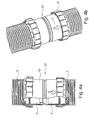
- exhaust pipe system 12 which comprises an exhaust pipe 1, which is inserted with a smooth pipe section 3 in a sleeve of a pipe section 13, such that a received in a molded annular groove 14 of the pipe section ring seal 15 from radially outward radially inwardly sealing can abut the outer circumference of the smooth tube section 3.
- the annular groove 14 forms on the outside an annular bead 16, which is engaged behind by the rear grip portions 10 of the securing element 8, which engages with its engagement means 9, the securing means 5 of the exhaust pipe 1 in the circumferential direction.
- a further exhaust pipe system 12 is shown, with a pipe section 13 formed here as an adapter piece, which is characterized by two sleeve pipe sections pointing in different axial direction.
- a pipe section 13 formed here as an adapter piece, which is characterized by two sleeve pipe sections pointing in different axial direction.
- exhaust pipe 1 is added.
- An example here designed as an arrow mark 17 on the exemplary only designed as an adapter piece of pipe shows a circumferential position, to which the securing element 8 is rotatable, so that an axial backup is given and preferably also a lock against accidental loosening.
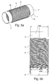
- Fig. 5a and 5b show an alternative embodiment of only partially shown exhaust pipe 1 with smooth pipe sections 3 and a corrugated pipe section 2, which simultaneously forms the securing means 5 in the embodiment shown.
- the corrugated pipe section 2 is formed as an external thread.
- the shafts have the shape of an external thread, ie they are arranged helically with a pitch, wherein both axial ends of the corrugated pipe section 2 are formed as a threaded inlet 18, on the circumferential direction, an internal thread of a correspondingly formed securing element can be screwed.
- the securing means 5 are hollow inside or formed as an inner recess, namely as circumferentially extending grooves, here as circumferentially extending gutter spiral, whereas in the embodiment according to Fig. 1b formed there as a bayonet locking part securing means 5 are formed as formed in a radial plane, in the circumferential direction and in the radial direction outwardly extending recesses.
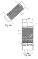
- a further alternative embodiment of an exhaust pipe 1 shown in detail is shown.
- the corrugated pipe sections 2 are designed classically, ie not as a thread or waves with increasing slope in the circumferential direction, but rather as in the embodiment according to Fig. 1a to 1 c.
- the shaft geometry comprises a plurality of axially adjacent shafts, which are each located in a radial plane. Each shaft is formed from the inside as a circumferentially closed ring.
- securing means 5 Adjacent to each axial end of a corrugated pipe section 2 securing means 5 are provided, which are integrally formed on the exhaust pipe 1, that is formed integrally therewith. It is in each case an external thread section, which in the illustrated embodiment consists of something above a threaded thread on which an internal thread of a correspondingly formed securing element for axial securing can be screwed. Not shown are locking means, which are also in the embodiments according to the Fig. 6a and 6b or 5a and 5b may be provided, for example as a radial increase or depression in a male thread.
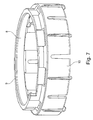
- a fuse element 8 is shown. This has in the region of an axial end lug-like rear grip portions for engaging behind a torus of a socket pipe-like piece of pipe, and axially spaced therefrom engagement means 9 in the form of an internal thread, which is matched to an external thread securing means of an exhaust pipe such that the engagement means 9 of the securing element 8 with the External thread of the exhaust pipe screwed and thereby the Secured element 8 and, as a result, a piece of pipe held by the securing element 8 are axially secured to the exhaust pipe.
- FIG. 8a and 8b is shown in partially sectioned view of an exhaust pipe system 12, wherein the exhaust pipe as in the embodiment according to the Fig. 6a and 6b is formed, wherein, of course, an exhaust pipe according to the Fig. 5a and 5b could be used.
- the exhaust pipe 1 comprises a corrugated pipe section and a smooth pipe section 3 introduced into the adjacent pipe section.
- the pipe section 13 and the exhaust pipe 1 are connected via a securing element 8, as shown by way of example in FIG Fig. 7 is shown, axially secured together.
- a securing element 8 engage here formed as an internal thread engaging means 9 of the securing element 8 and formed as male thread portion securing means 5 of the exhaust pipe 1 in the circumferential direction into one another, ie are screwed together in the concrete embodiment.
- the internal thread of the securing element 8 does not have to be a complete internal thread; here an internal threading section is sufficient. It is essential that the engagement means 9 are formed such that they can be screwed in a form-fitting manner by screwing to the externally threaded portion of the exhaust pipe 1.
Landscapes
- Engineering & Computer Science (AREA)
- General Engineering & Computer Science (AREA)
- Mechanical Engineering (AREA)
- Exhaust Silencers (AREA)
Priority Applications (1)
| Application Number | Priority Date | Filing Date | Title |
|---|---|---|---|
| EP16151928.5A EP3040594B1 (fr) | 2013-02-01 | 2013-07-01 | Tuyau de gaz d'echappement et systeme de tuyau de gaz d'echappement |
Applications Claiming Priority (1)
| Application Number | Priority Date | Filing Date | Title |
|---|---|---|---|
| DE102013101067.9A DE102013101067A1 (de) | 2013-02-01 | 2013-02-01 | Abgasrohr sowie Abgasrohrsystem |
Related Child Applications (2)
| Application Number | Title | Priority Date | Filing Date |
|---|---|---|---|
| EP16151928.5A Division-Into EP3040594B1 (fr) | 2013-02-01 | 2013-07-01 | Tuyau de gaz d'echappement et systeme de tuyau de gaz d'echappement |
| EP16151928.5A Division EP3040594B1 (fr) | 2013-02-01 | 2013-07-01 | Tuyau de gaz d'echappement et systeme de tuyau de gaz d'echappement |
Publications (3)
| Publication Number | Publication Date |
|---|---|
| EP2762761A2 true EP2762761A2 (fr) | 2014-08-06 |
| EP2762761A3 EP2762761A3 (fr) | 2014-10-15 |
| EP2762761B1 EP2762761B1 (fr) | 2016-04-06 |
Family
ID=48803382
Family Applications (2)
| Application Number | Title | Priority Date | Filing Date |
|---|---|---|---|
| EP13174531.7A Active EP2762761B1 (fr) | 2013-02-01 | 2013-07-01 | Tuyau d'échappement et système de tuyau d'échappement |
| EP16151928.5A Active EP3040594B1 (fr) | 2013-02-01 | 2013-07-01 | Tuyau de gaz d'echappement et systeme de tuyau de gaz d'echappement |
Family Applications After (1)
| Application Number | Title | Priority Date | Filing Date |
|---|---|---|---|
| EP16151928.5A Active EP3040594B1 (fr) | 2013-02-01 | 2013-07-01 | Tuyau de gaz d'echappement et systeme de tuyau de gaz d'echappement |
Country Status (2)
| Country | Link |
|---|---|
| EP (2) | EP2762761B1 (fr) |
| DE (1) | DE102013101067A1 (fr) |
Cited By (9)
| Publication number | Priority date | Publication date | Assignee | Title |
|---|---|---|---|---|
| EP2957829A1 (fr) * | 2014-06-18 | 2015-12-23 | Stefano Bächle | Tuyau de gaz d'échappement, système de tuyau de gaz d'échappement, ainsi que procédé de montage |
| DE202015100214U1 (de) | 2015-01-19 | 2016-04-20 | Stefano Bächle | Abgasrohrsystem |
| CN105546563A (zh) * | 2014-11-03 | 2016-05-04 | 上海机电工程研究所 | 一种刚柔结合的油机排烟转接装置 |
| EP3045796A1 (fr) | 2015-01-19 | 2016-07-20 | Stefano Bächle | Tuyau de gaz d'échappement, système de tuyau de gaz d'échappement, ainsi que procédé de démontage |
| EP3086012A1 (fr) | 2015-04-22 | 2016-10-26 | Stefano Bächle | Tuyau d'echappement, systeme et procede de fabrication d'une section de tuyau d'echappement |
| DE102015107746A1 (de) | 2015-04-22 | 2016-10-27 | Stefano Bächle | Abgasrohr, System sowie Verfahren zum Herstellen eines Abgasrohrabschnittes |
| EP3214353A1 (fr) | 2016-03-02 | 2017-09-06 | Dieter Bächle | Unite de tuyau pour l'aeration aussi que l'extraction des gaz d'echappement des equipments de combustion |
| DE102017112874A1 (de) * | 2017-06-12 | 2018-12-13 | Schiedel Gmbh | Anschlussvorrichtung, System aus einer Zwischenplatte und einer Anschlussvorrichtung, Vorrichtung zum Betrieb einer Feuerstätte und ein Verfahren zum Verbinden eines Doppelrohrs mit einer Feuerstätte |
| CN114876621A (zh) * | 2022-05-20 | 2022-08-09 | 四川川环科技股份有限公司 | Obd连接器、具有该obd连接器的排气管组合件及装配方法 |
Families Citing this family (3)
| Publication number | Priority date | Publication date | Assignee | Title |
|---|---|---|---|---|
| DE102017107498A1 (de) | 2017-04-07 | 2018-10-11 | Stefano Bächle | Einstückiges Kunststoff-Abgasrohr sowie Abgassystem |
| DE102017116818A1 (de) | 2017-07-25 | 2019-01-31 | Stefano Bächle | Sicherungsring, Abgasrohrsystem mit Sicherungsring sowie Sicherungsringbausatz |
| DE102017117021A1 (de) | 2017-07-27 | 2019-01-31 | Stefano Bächle | Einstückiges Kunststoff-Abgasrohr sowie Abgassystem |
Citations (2)
| Publication number | Priority date | Publication date | Assignee | Title |
|---|---|---|---|---|
| EP1024321B1 (fr) | 1999-01-29 | 2007-03-14 | Bächle, Dieter | Tuyau avec sections lisses et ondulées disposées en alternance |
| US7240930B2 (en) | 2004-02-23 | 2007-07-10 | Stravitz David M | Quick-connect/quick-disconnect conduit connectors |
Family Cites Families (11)
| Publication number | Priority date | Publication date | Assignee | Title |
|---|---|---|---|---|
| NL121816C (fr) * | 1959-06-25 | |||
| US3929359A (en) | 1974-11-04 | 1975-12-30 | Hancock Brick & Tile Co | Connecting joint structure for corrugated plastic tubing |
| US5165732A (en) | 1991-04-05 | 1992-11-24 | Simpson Dura Vent Company, Inc. | Gas appliance connection |
| DE4121557A1 (de) * | 1991-06-28 | 1993-01-07 | Schiedel Gmbh & Co | Bausatz aus metallrohren fuer den schornsteinbau, verfahren zum herstellen eines innenrohrstranges mittels des bausatzes sowie anwendungen |
| DE9418274U1 (de) * | 1994-11-15 | 1995-01-05 | Bertrams AG, 57072 Siegen | Rohrelement aus Edelstahl zum Erstellen von Schornsteinen sowie von Abgas- und Abdampfleitungen |
| DE10139899B4 (de) * | 2001-08-14 | 2009-09-10 | Fränkische Rohrwerke Gebr. Kirchner GmbH + Co. KG | Kunststoffwellrohranordnung |
| US7017953B2 (en) * | 2003-12-08 | 2006-03-28 | General Motors Corporation | Twist lock assembly |
| DE102005020603A1 (de) * | 2004-09-22 | 2006-03-23 | Dieter Bächle | Rohrstrang mit abwechselnd angeordneten glatten Rohrabschnitten und Wellrohrabschnitten |
| DE102005045482B4 (de) * | 2004-09-29 | 2008-12-18 | Bächle, Dieter | Rohreinheit mit wenigstens zwei in einem Verbindungsbereich aneinander gefügten Leitungsrohren |
| US8672367B2 (en) | 2006-05-02 | 2014-03-18 | M&G DuraVent, Inc. | Exhaust system interlocking mechanism |
| EP2000723A1 (fr) * | 2007-06-08 | 2008-12-10 | Plastiflex Belgium | Conduite de fluides dotée de sections rigides alternant avec des sections souples |
-
2013
- 2013-02-01 DE DE102013101067.9A patent/DE102013101067A1/de not_active Withdrawn
- 2013-07-01 EP EP13174531.7A patent/EP2762761B1/fr active Active
- 2013-07-01 EP EP16151928.5A patent/EP3040594B1/fr active Active
Patent Citations (2)
| Publication number | Priority date | Publication date | Assignee | Title |
|---|---|---|---|---|
| EP1024321B1 (fr) | 1999-01-29 | 2007-03-14 | Bächle, Dieter | Tuyau avec sections lisses et ondulées disposées en alternance |
| US7240930B2 (en) | 2004-02-23 | 2007-07-10 | Stravitz David M | Quick-connect/quick-disconnect conduit connectors |
Cited By (11)
| Publication number | Priority date | Publication date | Assignee | Title |
|---|---|---|---|---|
| EP2957829A1 (fr) * | 2014-06-18 | 2015-12-23 | Stefano Bächle | Tuyau de gaz d'échappement, système de tuyau de gaz d'échappement, ainsi que procédé de montage |
| CN105546563A (zh) * | 2014-11-03 | 2016-05-04 | 上海机电工程研究所 | 一种刚柔结合的油机排烟转接装置 |
| DE202015100214U1 (de) | 2015-01-19 | 2016-04-20 | Stefano Bächle | Abgasrohrsystem |
| EP3045796A1 (fr) | 2015-01-19 | 2016-07-20 | Stefano Bächle | Tuyau de gaz d'échappement, système de tuyau de gaz d'échappement, ainsi que procédé de démontage |
| EP3086012A1 (fr) | 2015-04-22 | 2016-10-26 | Stefano Bächle | Tuyau d'echappement, systeme et procede de fabrication d'une section de tuyau d'echappement |
| DE102015107746A1 (de) | 2015-04-22 | 2016-10-27 | Stefano Bächle | Abgasrohr, System sowie Verfahren zum Herstellen eines Abgasrohrabschnittes |
| DE102015107746B4 (de) * | 2015-04-22 | 2016-12-15 | Stefano Bächle | Abgasrohr, System sowie Verfahren zum Herstellen eines Abgasrohrabschnittes |
| EP3214353A1 (fr) | 2016-03-02 | 2017-09-06 | Dieter Bächle | Unite de tuyau pour l'aeration aussi que l'extraction des gaz d'echappement des equipments de combustion |
| DE102017112874A1 (de) * | 2017-06-12 | 2018-12-13 | Schiedel Gmbh | Anschlussvorrichtung, System aus einer Zwischenplatte und einer Anschlussvorrichtung, Vorrichtung zum Betrieb einer Feuerstätte und ein Verfahren zum Verbinden eines Doppelrohrs mit einer Feuerstätte |
| CN114876621A (zh) * | 2022-05-20 | 2022-08-09 | 四川川环科技股份有限公司 | Obd连接器、具有该obd连接器的排气管组合件及装配方法 |
| CN114876621B (zh) * | 2022-05-20 | 2024-01-26 | 四川川环科技股份有限公司 | Obd连接器、具有该obd连接器的排气管组合件及装配方法 |
Also Published As
| Publication number | Publication date |
|---|---|
| DE102013101067A1 (de) | 2014-08-07 |
| EP2762761A3 (fr) | 2014-10-15 |
| EP2762761B1 (fr) | 2016-04-06 |
| EP3040594A1 (fr) | 2016-07-06 |
| EP3040594B1 (fr) | 2018-03-21 |
Similar Documents
| Publication | Publication Date | Title |
|---|---|---|
| EP2762761B1 (fr) | Tuyau d'échappement et système de tuyau d'échappement | |
| EP1845299B1 (fr) | Dispositif de raccordement pour un tuyau | |
| EP2304303B1 (fr) | Raccord par pression pour un tuyau, en particulier un tuyau en plastique ou un tuyau composite plastique-métal | |
| DE102015115890B4 (de) | Anordnung zur Herstellung einer Rohrverbindung | |
| EP2304300B1 (fr) | Manchon coulissant en plastique et raccord muni d'un tel manchon coulissant | |
| DE102015108596A1 (de) | Rohrkupplung | |
| DE102014108563B3 (de) | Abgasrohr, Abgasrohrsystem sowie Montageverfahren | |
| DE3815168A1 (de) | Steckkupplung zum ankuppeln eines schlauches an ein rohr | |
| EP2330326A1 (fr) | Composant tubulaire | |
| DE102012106232B3 (de) | Rohrverbinder, Abgasrohrsystem sowie Montageverfahren | |
| DE102015107746B4 (de) | Abgasrohr, System sowie Verfahren zum Herstellen eines Abgasrohrabschnittes | |
| DE102013101172B4 (de) | Abgasrohrsystem sowie Montageverfahren | |
| EP3086012B1 (fr) | Tuyau d'echappement, systeme et procede de fabrication d'une section de tuyau d'echappement | |
| DE60020212T2 (de) | Rohrverbindungselement, insbesondere für kunststoffrohre | |
| DE202009003184U1 (de) | Dichtungsvorrichtung zum Abdichten eines Durchbruchs | |
| DE102017117021A1 (de) | Einstückiges Kunststoff-Abgasrohr sowie Abgassystem | |
| EP0549860A1 (fr) | Dispositif d'accouplement de deux conduites, en particulier pour des conduites de carburant | |
| EP3199772B1 (fr) | Silencieux pour un système d'échappement | |
| WO2018178946A1 (fr) | Raccord de tuyaux | |
| DE102014011188B4 (de) | Flexibles, auziehbares, koaxiales Schlauchsystem | |
| DE102008027102B4 (de) | Doppelwand-Wellrohr und Formbacken für eine Vorrichtung zur Herstellung eines derartigen Doppelwand-Wellrohres | |
| EP3434953B1 (fr) | Bague de sécurité, système de tube de gaz d'échappement pourvu de bague de sécurité | |
| DE102017107498A1 (de) | Einstückiges Kunststoff-Abgasrohr sowie Abgassystem | |
| DE102008016950B4 (de) | Anordnung aus einem Außenrohr und einem darin eingesetzten Innenrohr | |
| EP3045796A1 (fr) | Tuyau de gaz d'échappement, système de tuyau de gaz d'échappement, ainsi que procédé de démontage |
Legal Events
| Date | Code | Title | Description |
|---|---|---|---|
| PUAI | Public reference made under article 153(3) epc to a published international application that has entered the european phase |
Free format text: ORIGINAL CODE: 0009012 |
|
| 17P | Request for examination filed |
Effective date: 20130701 |
|
| AK | Designated contracting states |
Kind code of ref document: A2 Designated state(s): AL AT BE BG CH CY CZ DE DK EE ES FI FR GB GR HR HU IE IS IT LI LT LU LV MC MK MT NL NO PL PT RO RS SE SI SK SM TR |
|
| AX | Request for extension of the european patent |
Extension state: BA ME |
|
| PUAL | Search report despatched |
Free format text: ORIGINAL CODE: 0009013 |
|
| AK | Designated contracting states |
Kind code of ref document: A3 Designated state(s): AL AT BE BG CH CY CZ DE DK EE ES FI FR GB GR HR HU IE IS IT LI LT LU LV MC MK MT NL NO PL PT RO RS SE SI SK SM TR |
|
| AX | Request for extension of the european patent |
Extension state: BA ME |
|
| RIC1 | Information provided on ipc code assigned before grant |
Ipc: F23J 13/04 20060101ALI20140911BHEP Ipc: F16L 37/113 20060101AFI20140911BHEP Ipc: F16L 25/00 20060101ALI20140911BHEP |
|
| R17P | Request for examination filed (corrected) |
Effective date: 20141217 |
|
| RBV | Designated contracting states (corrected) |
Designated state(s): AL AT BE BG CH CY CZ DE DK EE ES FI FR GB GR HR HU IE IS IT LI LT LU LV MC MK MT NL NO PL PT RO RS SE SI SK SM TR |
|
| 17Q | First examination report despatched |
Effective date: 20150413 |
|
| GRAP | Despatch of communication of intention to grant a patent |
Free format text: ORIGINAL CODE: EPIDOSNIGR1 |
|
| INTG | Intention to grant announced |
Effective date: 20151030 |
|
| GRAS | Grant fee paid |
Free format text: ORIGINAL CODE: EPIDOSNIGR3 |
|
| GRAA | (expected) grant |
Free format text: ORIGINAL CODE: 0009210 |
|
| AK | Designated contracting states |
Kind code of ref document: B1 Designated state(s): AL AT BE BG CH CY CZ DE DK EE ES FI FR GB GR HR HU IE IS IT LI LT LU LV MC MK MT NL NO PL PT RO RS SE SI SK SM TR |
|
| REG | Reference to a national code |
Ref country code: GB Ref legal event code: FG4D Free format text: NOT ENGLISH |
|
| REG | Reference to a national code |
Ref country code: AT Ref legal event code: REF Ref document number: 788208 Country of ref document: AT Kind code of ref document: T Effective date: 20160415 Ref country code: CH Ref legal event code: EP |
|
| REG | Reference to a national code |
Ref country code: IE Ref legal event code: FG4D Free format text: LANGUAGE OF EP DOCUMENT: GERMAN |
|
| REG | Reference to a national code |
Ref country code: DE Ref legal event code: R096 Ref document number: 502013002428 Country of ref document: DE |
|
| REG | Reference to a national code |
Ref country code: CH Ref legal event code: NV Representative=s name: BODENSEEPATENT GMBH, CH |
|
| REG | Reference to a national code |
Ref country code: FR Ref legal event code: PLFP Year of fee payment: 4 |
|
| REG | Reference to a national code |
Ref country code: LT Ref legal event code: MG4D Ref country code: NL Ref legal event code: MP Effective date: 20160406 |
|
| PG25 | Lapsed in a contracting state [announced via postgrant information from national office to epo] |
Ref country code: NL Free format text: LAPSE BECAUSE OF FAILURE TO SUBMIT A TRANSLATION OF THE DESCRIPTION OR TO PAY THE FEE WITHIN THE PRESCRIBED TIME-LIMIT Effective date: 20160406 |
|
| PG25 | Lapsed in a contracting state [announced via postgrant information from national office to epo] |
Ref country code: FI Free format text: LAPSE BECAUSE OF FAILURE TO SUBMIT A TRANSLATION OF THE DESCRIPTION OR TO PAY THE FEE WITHIN THE PRESCRIBED TIME-LIMIT Effective date: 20160406 Ref country code: PL Free format text: LAPSE BECAUSE OF FAILURE TO SUBMIT A TRANSLATION OF THE DESCRIPTION OR TO PAY THE FEE WITHIN THE PRESCRIBED TIME-LIMIT Effective date: 20160406 Ref country code: IS Free format text: LAPSE BECAUSE OF FAILURE TO SUBMIT A TRANSLATION OF THE DESCRIPTION OR TO PAY THE FEE WITHIN THE PRESCRIBED TIME-LIMIT Effective date: 20160806 Ref country code: LT Free format text: LAPSE BECAUSE OF FAILURE TO SUBMIT A TRANSLATION OF THE DESCRIPTION OR TO PAY THE FEE WITHIN THE PRESCRIBED TIME-LIMIT Effective date: 20160406 Ref country code: NO Free format text: LAPSE BECAUSE OF FAILURE TO SUBMIT A TRANSLATION OF THE DESCRIPTION OR TO PAY THE FEE WITHIN THE PRESCRIBED TIME-LIMIT Effective date: 20160706 |
|
| PG25 | Lapsed in a contracting state [announced via postgrant information from national office to epo] |
Ref country code: RS Free format text: LAPSE BECAUSE OF FAILURE TO SUBMIT A TRANSLATION OF THE DESCRIPTION OR TO PAY THE FEE WITHIN THE PRESCRIBED TIME-LIMIT Effective date: 20160406 Ref country code: HR Free format text: LAPSE BECAUSE OF FAILURE TO SUBMIT A TRANSLATION OF THE DESCRIPTION OR TO PAY THE FEE WITHIN THE PRESCRIBED TIME-LIMIT Effective date: 20160406 Ref country code: GR Free format text: LAPSE BECAUSE OF FAILURE TO SUBMIT A TRANSLATION OF THE DESCRIPTION OR TO PAY THE FEE WITHIN THE PRESCRIBED TIME-LIMIT Effective date: 20160707 Ref country code: PT Free format text: LAPSE BECAUSE OF FAILURE TO SUBMIT A TRANSLATION OF THE DESCRIPTION OR TO PAY THE FEE WITHIN THE PRESCRIBED TIME-LIMIT Effective date: 20160808 Ref country code: SE Free format text: LAPSE BECAUSE OF FAILURE TO SUBMIT A TRANSLATION OF THE DESCRIPTION OR TO PAY THE FEE WITHIN THE PRESCRIBED TIME-LIMIT Effective date: 20160406 Ref country code: ES Free format text: LAPSE BECAUSE OF FAILURE TO SUBMIT A TRANSLATION OF THE DESCRIPTION OR TO PAY THE FEE WITHIN THE PRESCRIBED TIME-LIMIT Effective date: 20160406 Ref country code: LV Free format text: LAPSE BECAUSE OF FAILURE TO SUBMIT A TRANSLATION OF THE DESCRIPTION OR TO PAY THE FEE WITHIN THE PRESCRIBED TIME-LIMIT Effective date: 20160406 |
|
| REG | Reference to a national code |
Ref country code: DE Ref legal event code: R097 Ref document number: 502013002428 Country of ref document: DE |
|
| PG25 | Lapsed in a contracting state [announced via postgrant information from national office to epo] |
Ref country code: CZ Free format text: LAPSE BECAUSE OF FAILURE TO SUBMIT A TRANSLATION OF THE DESCRIPTION OR TO PAY THE FEE WITHIN THE PRESCRIBED TIME-LIMIT Effective date: 20160406 Ref country code: DK Free format text: LAPSE BECAUSE OF FAILURE TO SUBMIT A TRANSLATION OF THE DESCRIPTION OR TO PAY THE FEE WITHIN THE PRESCRIBED TIME-LIMIT Effective date: 20160406 Ref country code: RO Free format text: LAPSE BECAUSE OF FAILURE TO SUBMIT A TRANSLATION OF THE DESCRIPTION OR TO PAY THE FEE WITHIN THE PRESCRIBED TIME-LIMIT Effective date: 20160406 Ref country code: SK Free format text: LAPSE BECAUSE OF FAILURE TO SUBMIT A TRANSLATION OF THE DESCRIPTION OR TO PAY THE FEE WITHIN THE PRESCRIBED TIME-LIMIT Effective date: 20160406 Ref country code: EE Free format text: LAPSE BECAUSE OF FAILURE TO SUBMIT A TRANSLATION OF THE DESCRIPTION OR TO PAY THE FEE WITHIN THE PRESCRIBED TIME-LIMIT Effective date: 20160406 |
|
| PLBE | No opposition filed within time limit |
Free format text: ORIGINAL CODE: 0009261 |
|
| STAA | Information on the status of an ep patent application or granted ep patent |
Free format text: STATUS: NO OPPOSITION FILED WITHIN TIME LIMIT |
|
| PG25 | Lapsed in a contracting state [announced via postgrant information from national office to epo] |
Ref country code: SM Free format text: LAPSE BECAUSE OF FAILURE TO SUBMIT A TRANSLATION OF THE DESCRIPTION OR TO PAY THE FEE WITHIN THE PRESCRIBED TIME-LIMIT Effective date: 20160406 |
|
| 26N | No opposition filed |
Effective date: 20170110 |
|
| PG25 | Lapsed in a contracting state [announced via postgrant information from national office to epo] |
Ref country code: MC Free format text: LAPSE BECAUSE OF FAILURE TO SUBMIT A TRANSLATION OF THE DESCRIPTION OR TO PAY THE FEE WITHIN THE PRESCRIBED TIME-LIMIT Effective date: 20160406 |
|
| REG | Reference to a national code |
Ref country code: IE Ref legal event code: MM4A |
|
| PG25 | Lapsed in a contracting state [announced via postgrant information from national office to epo] |
Ref country code: SI Free format text: LAPSE BECAUSE OF FAILURE TO SUBMIT A TRANSLATION OF THE DESCRIPTION OR TO PAY THE FEE WITHIN THE PRESCRIBED TIME-LIMIT Effective date: 20160406 |
|
| REG | Reference to a national code |
Ref country code: FR Ref legal event code: PLFP Year of fee payment: 5 |
|
| PG25 | Lapsed in a contracting state [announced via postgrant information from national office to epo] |
Ref country code: IE Free format text: LAPSE BECAUSE OF NON-PAYMENT OF DUE FEES Effective date: 20160701 |
|
| PG25 | Lapsed in a contracting state [announced via postgrant information from national office to epo] |
Ref country code: LU Free format text: LAPSE BECAUSE OF NON-PAYMENT OF DUE FEES Effective date: 20160701 |
|
| GBPC | Gb: european patent ceased through non-payment of renewal fee |
Effective date: 20170701 |
|
| PG25 | Lapsed in a contracting state [announced via postgrant information from national office to epo] |
Ref country code: GB Free format text: LAPSE BECAUSE OF NON-PAYMENT OF DUE FEES Effective date: 20170701 |
|
| PG25 | Lapsed in a contracting state [announced via postgrant information from national office to epo] |
Ref country code: HU Free format text: LAPSE BECAUSE OF FAILURE TO SUBMIT A TRANSLATION OF THE DESCRIPTION OR TO PAY THE FEE WITHIN THE PRESCRIBED TIME-LIMIT; INVALID AB INITIO Effective date: 20130701 |
|
| PG25 | Lapsed in a contracting state [announced via postgrant information from national office to epo] |
Ref country code: MT Free format text: LAPSE BECAUSE OF FAILURE TO SUBMIT A TRANSLATION OF THE DESCRIPTION OR TO PAY THE FEE WITHIN THE PRESCRIBED TIME-LIMIT Effective date: 20160406 Ref country code: CY Free format text: LAPSE BECAUSE OF FAILURE TO SUBMIT A TRANSLATION OF THE DESCRIPTION OR TO PAY THE FEE WITHIN THE PRESCRIBED TIME-LIMIT Effective date: 20160406 Ref country code: MK Free format text: LAPSE BECAUSE OF FAILURE TO SUBMIT A TRANSLATION OF THE DESCRIPTION OR TO PAY THE FEE WITHIN THE PRESCRIBED TIME-LIMIT Effective date: 20160406 |
|
| REG | Reference to a national code |
Ref country code: FR Ref legal event code: PLFP Year of fee payment: 6 |
|
| PG25 | Lapsed in a contracting state [announced via postgrant information from national office to epo] |
Ref country code: BG Free format text: LAPSE BECAUSE OF FAILURE TO SUBMIT A TRANSLATION OF THE DESCRIPTION OR TO PAY THE FEE WITHIN THE PRESCRIBED TIME-LIMIT Effective date: 20160406 |
|
| PG25 | Lapsed in a contracting state [announced via postgrant information from national office to epo] |
Ref country code: AL Free format text: LAPSE BECAUSE OF FAILURE TO SUBMIT A TRANSLATION OF THE DESCRIPTION OR TO PAY THE FEE WITHIN THE PRESCRIBED TIME-LIMIT Effective date: 20160406 Ref country code: TR Free format text: LAPSE BECAUSE OF FAILURE TO SUBMIT A TRANSLATION OF THE DESCRIPTION OR TO PAY THE FEE WITHIN THE PRESCRIBED TIME-LIMIT Effective date: 20160406 |
|
| REG | Reference to a national code |
Ref country code: CH Ref legal event code: PFA Owner name: BAECHLE, STEFANO, CH Free format text: FORMER OWNER: BAECHLE, STEFANO, CH |
|
| PGFP | Annual fee paid to national office [announced via postgrant information from national office to epo] |
Ref country code: AT Payment date: 20220727 Year of fee payment: 10 |
|
| PGFP | Annual fee paid to national office [announced via postgrant information from national office to epo] |
Ref country code: FR Payment date: 20220729 Year of fee payment: 10 Ref country code: BE Payment date: 20220728 Year of fee payment: 10 |
|
| PGFP | Annual fee paid to national office [announced via postgrant information from national office to epo] |
Ref country code: CH Payment date: 20220824 Year of fee payment: 10 |
|
| REG | Reference to a national code |
Ref country code: CH Ref legal event code: PL |
|
| REG | Reference to a national code |
Ref country code: AT Ref legal event code: MM01 Ref document number: 788208 Country of ref document: AT Kind code of ref document: T Effective date: 20230701 |
|
| REG | Reference to a national code |
Ref country code: BE Ref legal event code: MM Effective date: 20230731 |
|
| PG25 | Lapsed in a contracting state [announced via postgrant information from national office to epo] |
Ref country code: AT Free format text: LAPSE BECAUSE OF NON-PAYMENT OF DUE FEES Effective date: 20230701 |
|
| PG25 | Lapsed in a contracting state [announced via postgrant information from national office to epo] |
Ref country code: AT Free format text: LAPSE BECAUSE OF NON-PAYMENT OF DUE FEES Effective date: 20230701 Ref country code: CH Free format text: LAPSE BECAUSE OF NON-PAYMENT OF DUE FEES Effective date: 20230731 |
|
| PG25 | Lapsed in a contracting state [announced via postgrant information from national office to epo] |
Ref country code: FR Free format text: LAPSE BECAUSE OF NON-PAYMENT OF DUE FEES Effective date: 20230731 Ref country code: BE Free format text: LAPSE BECAUSE OF NON-PAYMENT OF DUE FEES Effective date: 20230731 |
|
| REG | Reference to a national code |
Ref country code: DE Ref legal event code: R084 Ref document number: 502013002428 Country of ref document: DE |
|
| PGFP | Annual fee paid to national office [announced via postgrant information from national office to epo] |
Ref country code: DE Payment date: 20250925 Year of fee payment: 13 |
|
| PGFP | Annual fee paid to national office [announced via postgrant information from national office to epo] |
Ref country code: IT Payment date: 20250731 Year of fee payment: 13 |