EP2762808A1 - Réfrigérateur - Google Patents
Réfrigérateur Download PDFInfo
- Publication number
- EP2762808A1 EP2762808A1 EP20120837519 EP12837519A EP2762808A1 EP 2762808 A1 EP2762808 A1 EP 2762808A1 EP 20120837519 EP20120837519 EP 20120837519 EP 12837519 A EP12837519 A EP 12837519A EP 2762808 A1 EP2762808 A1 EP 2762808A1
- Authority
- EP
- European Patent Office
- Prior art keywords
- refrigerator
- compartment
- cooling
- flow path
- opening
- Prior art date
- Legal status (The legal status is an assumption and is not a legal conclusion. Google has not performed a legal analysis and makes no representation as to the accuracy of the status listed.)
- Granted
Links
- 238000001816 cooling Methods 0.000 claims abstract description 184
- 230000004888 barrier function Effects 0.000 claims abstract description 48
- 238000010438 heat treatment Methods 0.000 claims description 15
- XLYOFNOQVPJJNP-UHFFFAOYSA-N water Substances O XLYOFNOQVPJJNP-UHFFFAOYSA-N 0.000 claims description 14
- 238000009413 insulation Methods 0.000 claims description 10
- 238000002844 melting Methods 0.000 claims description 3
- 230000008018 melting Effects 0.000 claims description 3
- 238000005057 refrigeration Methods 0.000 description 9
- 230000007423 decrease Effects 0.000 description 6
- 238000010586 diagram Methods 0.000 description 2
- 239000003507 refrigerant Substances 0.000 description 2
- 230000015572 biosynthetic process Effects 0.000 description 1
- 238000007906 compression Methods 0.000 description 1
- 230000001276 controlling effect Effects 0.000 description 1
- 230000003247 decreasing effect Effects 0.000 description 1
- 230000000694 effects Effects 0.000 description 1
- 238000001704 evaporation Methods 0.000 description 1
- 238000000034 method Methods 0.000 description 1
- 239000011295 pitch Substances 0.000 description 1
- 230000001105 regulatory effect Effects 0.000 description 1
- 238000010257 thawing Methods 0.000 description 1
Images
Classifications
-
- F—MECHANICAL ENGINEERING; LIGHTING; HEATING; WEAPONS; BLASTING
- F25—REFRIGERATION OR COOLING; COMBINED HEATING AND REFRIGERATION SYSTEMS; HEAT PUMP SYSTEMS; MANUFACTURE OR STORAGE OF ICE; LIQUEFACTION SOLIDIFICATION OF GASES
- F25D—REFRIGERATORS; COLD ROOMS; ICE-BOXES; COOLING OR FREEZING APPARATUS NOT OTHERWISE PROVIDED FOR
- F25D17/00—Arrangements for circulating cooling fluids; Arrangements for circulating gas, e.g. air, within refrigerated spaces
- F25D17/04—Arrangements for circulating cooling fluids; Arrangements for circulating gas, e.g. air, within refrigerated spaces for circulating air, e.g. by convection
- F25D17/06—Arrangements for circulating cooling fluids; Arrangements for circulating gas, e.g. air, within refrigerated spaces for circulating air, e.g. by convection by forced circulation
- F25D17/062—Arrangements for circulating cooling fluids; Arrangements for circulating gas, e.g. air, within refrigerated spaces for circulating air, e.g. by convection by forced circulation in household refrigerators
-
- F—MECHANICAL ENGINEERING; LIGHTING; HEATING; WEAPONS; BLASTING
- F25—REFRIGERATION OR COOLING; COMBINED HEATING AND REFRIGERATION SYSTEMS; HEAT PUMP SYSTEMS; MANUFACTURE OR STORAGE OF ICE; LIQUEFACTION SOLIDIFICATION OF GASES
- F25D—REFRIGERATORS; COLD ROOMS; ICE-BOXES; COOLING OR FREEZING APPARATUS NOT OTHERWISE PROVIDED FOR
- F25D2317/00—Details or arrangements for circulating cooling fluids; Details or arrangements for circulating gas, e.g. air, within refrigerated spaces, not provided for in other groups of this subclass
- F25D2317/06—Details or arrangements for circulating cooling fluids; Details or arrangements for circulating gas, e.g. air, within refrigerated spaces, not provided for in other groups of this subclass with forced air circulation
- F25D2317/063—Details or arrangements for circulating cooling fluids; Details or arrangements for circulating gas, e.g. air, within refrigerated spaces, not provided for in other groups of this subclass with forced air circulation with air guides
Definitions
- the present invention relates to a refrigerator, and more specifically to a structure of the refrigerator provided with two temperature zones and configured to prevent returning air used to cool one of compartments from escaping into another of the compartments.
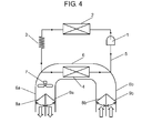
- Fig. 4 is a schematic diagram of a refrigeration cycle of a conventional refrigerator.
- the refrigeration cycle comprises refrigerant circuit 5 having compressor 1, condenser 2, pressure reducing device 3 and cooling unit 4 connected in series, and cold-air flow path 6.
- Cold-air flow path 6 allows cold air to flow through a freezer compartment of low temperature zone (not shown) and a refrigerator compartment of high temperature zone (not shown) wherein the two temperature zones are controlled by regulating cooling time and the like.
- Cold-air flow path 6 includes cooling unit 4, cooling fan 7, freezer-compartment flow damper 8a, refrigerator-compartment flow damper 9a, freezer-compartment return damper 8b, and refrigerator-compartment return damper 9b.
- Cooling fan 7 circulates the cold air to interiors of the refrigerator.
- Freezer-compartment flow damper 8a, refrigerator-compartment flow damper 9a, freezer-compartment return damper 8b and refrigerator-compartment return damper 9b are disposed to their respective locations in airflow path 6a and return flow path 6b so that the cold air can be circulated selectively to the freezer compartment and the refrigerator compartment.
- compressor 1 and cooling fan 7 are driven to operate the refrigeration cycle, when a temperature of the freezer compartment becomes higher than a preset temperature, and it becomes necessary to cool only the freezer compartment.
- freezer-compartment flow damper 8a and freezer-compartment return damper 8b are opened whereas refrigerator-compartment flow damper 9a and refrigerator-compartment return damper 9b are kept closed, to cool only the freezer compartment.
- refrigerator-compartment flow damper 9a and refrigerator-compartment return damper 9b are opened while freezer-compartment flow damper 8a and freezer-compartment return damper 8b are closed, to cool only the refrigerator compartment.
- Refrigerators hitherto disclosed include such a function capable of preventing cold air of a higher temperature from flowing into a freezer compartment of lower temperature zone by controlling in the above manner when cooling a refrigerator compartment of higher temperature zone, thereby suppressing a temperature rise of the freezer compartment to a minimum possible extent (refer to Patent Literature 1, for example).
- refrigerators of such a structure that prevents backflow of cold air to a freezer compartment by drawing the cold air used to cool a refrigerator compartment from a lower backside of cooling unit 4 whereas a return flow path of the freezer compartment side is opened in a location lower than that, as another method.
- an intake opening may be located at a back surface of cooling unit 4.
- such a structure will require additional measures of increasing fin pitches or eliminating some fins in lower part of cooling unit 4 when a cooling unit of fin-and-tube type is used, in order to prevent cooling unit 4 from being clogged due to formation of frost. It thus gives rise to problems that a capacity of cooling unit 4 decreases, and a size of cooling unit 4 increases in order to maintain the capacity that makes a volume of the compartment smaller.
- a refrigerator of the present invention comprises a first storage compartment, a second storage compartment, a cooling chamber, a cooling unit, a cooling fan, a first discharge flow path, a second discharge flow path, a first return flow path, and a second return flow path.
- the first storage compartment and the second storage compartment are surrounded by an insulation wall, and provided with an opening in a front face.
- the cooling chamber is located at a back-face side of the second storage compartment.
- the cooling unit is disposed inside the cooling chamber.
- the cooling fan forces cold air produced by the cooling unit to circulate to the first storage compartment and the second storage compartment.
- the first discharge flow path guides cooling air sent by the cooling fan into the first storage compartment.
- the second discharge flow path guides the cooling air sent by the cooling fan into the second storage compartment.
- the first return flow path guides the cooling air used to cool the first storage compartment back to the cooling chamber.
- the second return flow path guides the cooling air used to cool the second storage compartment back to the cooling chamber.
- the refrigerator of the present invention further comprises a first opening and a second opening.
- the first opening guides the cooling air from the first return flow path to the cooling chamber.
- the second opening is provided in a surface confronting the first opening in a depth direction, and guides the cooling air from the second return flow path to the cooling chamber.
- This structure can prevent the cold air used to cool the first storage compartment from flowing into the second storage compartment, and it can hence suppress a temperature rise of the second storage compartment with simple structure.
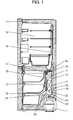
- Fig. 1 is a longitudinal sectional view of a refrigerator according to the first exemplary embodiment of the present invention.
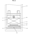
- Fig. 2 is a front view of the refrigerator with a door open according to the first embodiment of the invention.
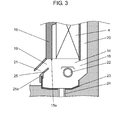
- Fig. 3 is a sectional view of a return flow path and the vicinity thereof in the refrigerator according to the first embodiment of the invention.
- refrigerator main cabinet 11 constructed with insulation wall includes refrigerator compartment 12 at an upper section and freezer compartment 13 at a lower section.
- Refrigerator main cabinet 11 is also provided internally with a refrigerant circuit having compressor 1, a condenser (not shown), a pressure reducing device (not shown), and cooling unit 4.
- Freezer compartment 13 has cooling chamber 14 in which cooling unit 4 is disposed. Cooling chamber 14 is separated from an interior of freezer compartment 13 by cooling unit cover 15.
- cooling fan 7 refrigerator-compartment flow damper 9a and freezer-compartment flow damper 8a, all disposed above cooling unit 4 for selectively circulating cold air (i.e., cooling air) produced by cooling unit 4 to refrigerator compartment 12 and freezer compartment 13.
- cold air i.e., cooling air
- Refrigerator-compartment flow damper 9a and an interior of refrigerator compartment 12 are connected via refrigerator-compartment discharge flow path 16, so that refrigerator compartment 12 and cooling chamber 14 come into continuity when refrigerator-compartment flow damper 9a opens.
- refrigerator-compartment flow damper 9a selectively closes and opens refrigerator-compartment discharge flow path 16.
- Refrigerator-compartment discharge flow path 16 guides the cooling air sent by cooling fan 7 toward refrigerator compartment 12.
- Freezer-compartment flow damper 8a and the interior of freezer compartment 13 are connected via freezer-compartment discharge flow path 17, so that freezer compartment 13 and cooling chamber 14 come into continuity when freezer-compartment flow damper 8a opens. That is, freezer-compartment flow damper 8a selectively closes and opens freezer-compartment discharge flow path 17. Freezer-compartment discharge flow path 17 guides the cooling air sent by cooling fan 7 toward freezer compartment 13. Both refrigerator-compartment flow damper 9a and freezer-compartment flow damper 8a do not open simultaneously during operation of cooling fan 7.
- Refrigerator-compartment intake opening 18 is provided in a back face of cooling chamber 14 below cooling unit 4, and freezer-compartment intake opening 19 is provided in a front face of cooling chamber 14, and they are opened to communicate with refrigerator-compartment return flow path 20 and freezer-compartment return flow path 21 respectively.
- freezer-compartment intake opening 19 is provided in the surface confronting refrigerator-compartment intake opening 18 in a depth direction.
- Refrigerator-compartment return flow path 20 that has a width nearly equal to or larger than a width of cooling unit 4 is disposed between cooling chamber 14 and refrigerator main cabinet 11.
- Refrigerator-compartment return flow path 20 guides the cold air used to cool refrigerator compartment 12 back again to cooling chamber 14.
- Freezer-compartment return flow path 21 is disposed under cooling unit cover 15. Freezer-compartment return flow path 21 guides the cold air used to cool freezer compartment 13 back again to cooling chamber 14.
- Heating unit 22 such as a radiant heater is disposed below cooling unit 4 at a position between an upper edge and a lower edge of an opening of refrigerator-compartment intake opening 18, for melting frost built up on cooling unit 4 during refrigerating operation.
- water cutting edge 15a of a ridge shape is formed downward at one side facing cooling unit 4 of the lower end of cooling unit cover 15.
- Inflow barrier wall 25 is provided at a lower part of cooling unit cover 15.
- Inflow barrier wall 25 has a shape of rectangular plate with a width that is at least larger than a width of refrigerator-compartment intake opening 18.
- inflow barrier wall 25 has fitting portion 25a at a lower side thereof for engagement with a front wall of drip tray 23. This is to eliminate a gap between inflow barrier wall 25 and drip tray 23, and reduce variation in position of inflow barrier wall 25.
- Inflow barrier wall 25 is disposed at a position forward of a plane projected in a direction perpendicularly downward from cooling unit 4 with its surface inclined such that an upper edge is closer to a back-face side of refrigerator main cabinet 11 than a lower edge. Inflow barrier wall 25 is disposed between refrigerator-compartment intake opening 18 and freezer-compartment intake opening 19, and it prevents the cold air discharged through refrigerator-compartment intake opening 18 from flowing backward into freezer-compartment intake opening 19 and entering freezer compartment 13 through freezer-compartment return flow path 21.
- the refrigerator constructed above operates in a manner as described hereinafter.
- compressor 1 When a temperature inside freezer compartment 13 exceeds a reference temperature due to temperature rise in the compartment, and it becomes necessary to cool down freezer compartment 13 during operation of the refrigerator, compressor 1 is started to operate if it is not in operation. If compressor 1 is already in operation, on the other hand, the operation of compressor 1 is continued. At the same time, cooling fan 7 is operated, freezer-compartment flow damper 8a is opened, and refrigerator-compartment flow damper 9a is closed.
- cooling unit 4 flows into freezer compartment 13 from freezer-compartment flow damper 8a through freezer-compartment discharge flow path 17, and cools the interior of freezer compartment 13.
- freezer-compartment return flow path 21 and freezer-compartment intake opening 19 the cold air that has cooled freezer compartment 13 is drawn into freezer-compartment return flow path 21 and freezer-compartment intake opening 19 in this order, and discharged by cooling fan 7 into the interior of freezer compartment 13 from freezer-compartment flow damper 8a and freezer-compartment discharge flow path 17 after it is cooled again by cooling unit 4.
- refrigerator-compartment flow damper 9a is opened, and freezer-compartment flow damper 8a is closed.
- cooling unit 4 flows into refrigerator compartment 12 from refrigerator-compartment flow damper 9a through refrigerator-compartment discharge flow path 16, and cools the interior of refrigerator compartment 12.
- refrigerator-compartment return flow path 20 and refrigerator-compartment intake opening 18 in this order, and the cold air discharged from refrigerator-compartment intake opening 18 is forced by inflow barrier wall 25 to change its direction of flow toward cooling unit 4.
- the cold air is again cooled thereafter, and discharged by cooling fan 7 into the interior of refrigerator compartment 12 from refrigerator-compartment flow damper 9a and refrigerator-compartment discharge flow path 16.
- inflow barrier wall 25 is not provided here, the cold air drawn from refrigerator-compartment intake opening 18 climbs over a front wall of drip tray 23, flows backward and enters freezer compartment 13 from freezer-compartment intake opening 19 and freezer-compartment return flow path 21. At this time, the cold air entering from refrigerator compartment intake opening 18 is higher in temperature than that inside freezer compartment 13 because it has cooled refrigerator compartment 12, it causes the temperature of freezer compartment 13 to rise.
- inflow barrier wall 25 When inflow barrier wall 25 is provided, on the other hand, the cold air drawn from refrigerator-compartment intake opening 18 is forced to flow along inflow barrier wall 25 from drip tray 23. Since the cold air is forced to change the direction of flow toward cooling unit 4, the cold air does not flow into freezer-compartment intake opening 19.
- freezer compartment 13 never become warmed up by the cold air already used to cool refrigerator compartment 12 during the cooling operation of refrigerator compartment 12, even though freezer-compartment intake opening 19 is not provided with a damper like the example of conventional art. It becomes possible for this reason to suppress reliably the temperature rise of freezer compartment 13 with a less-costly structure, which can provide the refrigerator of high refrigerating performance.
- refrigerator-compartment return flow path 20 is disposed between cooling chamber 14 and the insulation wall on the back face of refrigerator main cabinet 11, and so configured as to have the width nearly equal to or larger than the width of cooling unit 4.
- This configuration can reduce a difference in the temperatures between the outside air through the insulation wall and inside of refrigerator main cabinet 11.
- a temperature of the cold air that flows in refrigerator-compartment return flow path 20 increases as compared to the structure of conventional art although an amount of heat transfer decreases and the insulating effect increases.
- the cold air is circulated only through refrigerator compartment 12 by keeping freezer-compartment flow damper 8a closed when cooling refrigerator compartment 12.
- the temperature of cooling unit 4 can be increased as compared with other cases in which freezer-compartment flow damper 8a is not provided or freezer-compartment flow damper 8a is not closed during cooling operation of refrigerator compartment 12.
- the temperature of the cold air that flows in refrigerator-compartment return flow path 20 increases even further, though the efficiency of the cooling cycle increases during the cooling operation of refrigerator compartment 12.
- both refrigerator-compartment intake opening 18 and freezer-compartment intake opening 19 are opened in an area perpendicularly below cooling unit 4.
- the temperature rise of freezer compartment 13 can therefore be suppressed without impairing the efficiency of cooling unit 4, thereby providing the refrigerator of high refrigerating performance.
- inflow barrier wall 25 is fixed to drip tray 23 by engagement of fitting portion 25a. Therefore, the cold air used to cool refrigerator compartment 12 can be directed toward cooling unit 4 by drip tray 23 and inflow barrier wall 25. As a result, drip tray 23 can be used as an airflow path, and this helps reduce the size of inflow barrier wall 25. In addition, this structure does not allow any gap to arise between drip tray 23 and inflow barrier wall 25 due to variations in their dimensions and assembling, and to cause any leakage of the cold air into freezer compartment 13 through such a gap, since inflow barrier wall 25 is fixed to drip tray 23 by the engagement of fitting portion 25a.
- Inflow barrier wall 25 is formed as an integral structure with cooling unit cover 15. This helps make inflow barrier wall 25 even less costly since it can decrease a number of the components.
- refrigerator-compartment intake opening 18 is opened across an area from a position higher than heating unit 22 to a position lower than the same. Because of this configuration, the cold air used to cool refrigerator compartment 12 is discharged from refrigerator-compartment intake opening 18, in which a part of the cold air from the position lower than heating unit 22 is guided along drip tray 23 toward inflow barrier wall 25 and drawn into cooling unit 4, and another part of the cold air from the position higher than heating unit 22 is drawn directly into cooling unit 4.
- refrigerator-compartment intake opening 18 is opened only in one position higher than heating unit 22, the cold air from refrigerator-compartment intake opening 18 is forced to change the direction sharply when being drawn into cooling unit 4, which results in a large loss of the pressure.
- refrigerator-compartment intake opening 18 is opened only in another position lower than heating unit 22, all the cold air discharged from refrigerator-compartment intake opening 18 flows from drip tray 23 toward inflow barrier wall 25, which increases a velocity of the air. It therefore becomes necessary to tilt inflow barrier wall 25 further toward cooling unit 4 in order to prevent the cold air from escaping into freezer compartment 13, which also results in a large loss of the pressure.
- heating unit 22 When choosing another structure in which heating unit 22 is spaced away from refrigerator-compartment intake opening 18 to reduce the pressure loss, it is necessary to maintain a certain distance between heating unit 22 and adjacent components to ensure safety. This requires an increase in size of cooling chamber 14, which decreases an internal volume of the compartment.
- refrigerator-compartment intake opening 18 when refrigerator-compartment intake opening 18 is opened at such height dimensions from the position higher than heating unit 22 to the position lower than the heating unit 22, the temperature rise of freezer compartment 13 can be suppressed by reducing the pressure loss in the airflow path without decreasing the internal volume of the compartment, thereby providing the refrigerator of high refrigerating performance.
- inflow barrier wall 25 is located outside of the plane projected in the direction perpendicularly downward from cooling unit 4, melted water produced during defrosting operation of the frost built up on cooling unit 4 never goes out along inflow barrier wall 25 to escape into freezer compartment 13.
- cooling unit cover 15 is provided with water cutting edge 15a. Because of this structure, the water melted on the surface of cooling unit 4 drips down from water cutting edge 15a even when it flows along the surface of cooling unit cover 15. Therefore, there is never any leakage of water along cooling unit cover 15 and escape into freezer compartment 13.
- inflow barrier wall 25 is so configured that an upper edge of inflow barrier wall 25 is situated further toward the front side of refrigerator main cabinet 11 than water cutting edge 15a. This configuration prevents the water that drips down from water cutting edge 15a from escaping along inflow barrier wall 25 and into freezer compartment 13.
- the refrigerator described in this embodiment is configured to have freezer compartment 13 at the top and refrigerator compartment 12 at the bottom, similar advantages can be achieved with other configurations such that freezer compartment 13 and refrigerator compartment 12 are disposed side by side, so long as the refrigerator has two temperature zones.
- the refrigerator described in this embodiment is provided with two storage compartments, i.e., freezer compartment 13 and refrigerator compartment 12, similar advantages can also be achieved with any refrigerator having a plurality of storage compartments so long as the refrigerator includes an intake opening in both the front side and the backside of cooling chamber 14.
- the refrigerator described in this embodiment is provided with the refrigeration system for producing cold air with a refrigerant-compression type refrigeration cycle using compressor 1, similar advantages can also be achieved with any refrigeration system capable of producing cold air with cooling unit 4.
- the refrigerator of the present invention comprises a first storage compartment, a second storage compartment, a cooling chamber, a cooling unit, a cooling fan, a first discharge flow path, a second discharge flow path, a first return flow path, and a second return flow path.
- the first storage compartment and the second storage compartment are surrounded by an insulation wall, and provided with an opening in a front face.
- the cooling chamber is located at a back-face side of the second storage compartment.
- the cooling unit is disposed inside the cooling chamber.
- the cooling fan forces cold air produced by the cooling unit to circulate to the first storage compartment and the second storage compartment.
- the first discharge flow path guides cooling air sent by the cooling fan into the first storage compartment.
- the second discharge flow path guides the cooling air sent by the cooling fan into the second storage compartment.
- the first return flow path guides the cooling air used to cool the first storage compartment back to the cooling chamber.
- the second return flow path guides the cooling air used to cool the second storage compartment back to the cooling chamber.
- the refrigerator of the present invention further comprises a first opening and a second opening.
- the first opening guides the cooling air from the first return flow path to the cooling chamber.
- the second opening is located in a surface confronting the first opening in a depth direction, and guides the cooling air from the second return flow path toward the cooling chamber.
- the inflow barrier wall in the refrigerator of this invention causes the cooling air discharger from the first opening to change the direction toward the cooling unit.
- This structure lets the cold air used to cool the first storage compartment flow entirely into the cooling unit without allowing it to flow toward the return flow-path side of the first storage compartment, thereby suppressing the temperature rise of the second storage compartment reliably.
- the first return flow path is disposed to the back-face side of the cooling chamber, and the second return flow path is disposed to the front-face side of the cooling chamber.
- This configuration makes up a structure of high insulation property by having the return flow path of a temperature higher than that of the cooling unit between the cooling unit and the insulation wall, thereby suppressing even further the temperature rise of the second storage compartment.
- first opening and the second opening are located in the positions perpendicularly below the cooling unit, in the refrigerator of the present invention.
- This configuration draws the returning cold air from under the cooling unit, and allows the cold air to flow efficiently through the entire cooling unit. As a result, it can improve the cooling efficiency of the refrigerator.
- the refrigerator of the present invention is provided with a dish-like drip tray for catching water resulting from melted frost built up on the cooling unit.
- the cooling air discharged from the first opening is guided in a direction of the cooling unit by a wall on the second opening side of the drip tray and the inflow barrier wall.
- This structure can make use of the drip tray and the inflow barrier wall to guide the cold air that has cooled the refrigerator compartment smoothly toward the cooling unit, and thereby reduce a size of the inflow barrier wall.
- the structure can hence suppress the temperature rise of the second storage compartment.
- the refrigerator of the present invention is also provided with a first flow-path choke device for selectively opening and closing the first discharge flow path, and a second flow-path choke device for selectively opening and closing the second discharge flow path.
- the first flow-path choke device and the second flow-path choke device are not opened simultaneously while the cooling fan is in operation.
- the structure can prevent the cold air that has cooled the first storage compartment all by itself from entering the second storage compartment. It thus becomes possible to increase an evaporating temperature when cooling the first storage compartment, and improve the efficiency of the refrigeration cycle.
- a temperature of the first storage compartment is higher than that of the second storage compartment.
- the inflow barrier wall is located outside of a plane projected in a direction perpendicularly downward from the cooling unit.
- the refrigerator of the present invention is also provided with a fitting portion between the inflow barrier wall and the drip tray.
- This structure can form an airflow path without leaving any gap between the inflow barrier wall and the drip tray. It thus eliminates any leakage of the cold air between the inflow barrier wall and the drip tray, and further suppresses the temperature rise of the freezer compartment.
- the refrigerator of the present invention is also provided internally with a first discharge flow path, a first return flow path, a first choke device, and a second choke device. Also provided is a cover that separates the cooling unit and the second storage compartment, and that the cover and the inflow barrier wall are formed into an integral structure.
- This structure can reduce a number of components. Because of this structure, the airflow path can be configured with a low cost, in addition to reducing variations in assembling, and further suppressing the temperature rise of the freezer compartment with a far less cost.
- the refrigerator of the present invention has a heating unit disposed at a position between an upper edge and a lower edge of the first opening, for melting the frost built up on the cooling unit.
- This structure allows the cold air to flow through both the upper and lower sides of the heating unit, which reduces a resistance in the airflow path and limits a decrease in volume of the airflow by the cooling fan. As a result, this can provide the refrigerator with high refrigeration efficiency.
- the present invention pertains to a refrigerator having two storage compartments, and provides the refrigerator with capability of refrigerating these storage compartments highly efficiently.
- the present invention is therefore applicable to refrigerators of various kinds and sizes for domestic use, commercial use and the like.
Landscapes
- Engineering & Computer Science (AREA)
- Chemical & Material Sciences (AREA)
- Combustion & Propulsion (AREA)
- Physics & Mathematics (AREA)
- Mechanical Engineering (AREA)
- Thermal Sciences (AREA)
- General Engineering & Computer Science (AREA)
- Cold Air Circulating Systems And Constructional Details In Refrigerators (AREA)
Applications Claiming Priority (2)
| Application Number | Priority Date | Filing Date | Title |
|---|---|---|---|
| JP2011213943A JP5903552B2 (ja) | 2011-09-29 | 2011-09-29 | 冷蔵庫 |
| PCT/JP2012/005831 WO2013046580A1 (fr) | 2011-09-29 | 2012-09-13 | Réfrigérateur |
Publications (3)
| Publication Number | Publication Date |
|---|---|
| EP2762808A1 true EP2762808A1 (fr) | 2014-08-06 |
| EP2762808A4 EP2762808A4 (fr) | 2015-06-17 |
| EP2762808B1 EP2762808B1 (fr) | 2016-11-02 |
Family
ID=47994669
Family Applications (1)
| Application Number | Title | Priority Date | Filing Date |
|---|---|---|---|
| EP12837519.3A Not-in-force EP2762808B1 (fr) | 2011-09-29 | 2012-09-13 | Réfrigérateur |
Country Status (4)
| Country | Link |
|---|---|
| EP (1) | EP2762808B1 (fr) |
| JP (1) | JP5903552B2 (fr) |
| CN (1) | CN103827608B (fr) |
| WO (1) | WO2013046580A1 (fr) |
Cited By (1)
| Publication number | Priority date | Publication date | Assignee | Title |
|---|---|---|---|---|
| EP2789940A4 (fr) * | 2011-12-06 | 2015-06-03 | Panasonic Corp | Réfrigérateur |
Families Citing this family (17)
| Publication number | Priority date | Publication date | Assignee | Title |
|---|---|---|---|---|
| JP6023986B2 (ja) * | 2013-06-06 | 2016-11-09 | パナソニックIpマネジメント株式会社 | 冷蔵庫 |
| JP6145640B2 (ja) * | 2013-06-06 | 2017-06-14 | パナソニックIpマネジメント株式会社 | 冷蔵庫 |
| JP6145642B2 (ja) * | 2013-06-06 | 2017-06-14 | パナソニックIpマネジメント株式会社 | 冷蔵庫 |
| JP6145639B2 (ja) * | 2013-06-06 | 2017-06-14 | パナソニックIpマネジメント株式会社 | 冷蔵庫 |
| CN205482060U (zh) * | 2013-06-06 | 2016-08-17 | 松下知识产权经营株式会社 | 冷藏库 |
| JP6145643B2 (ja) * | 2013-06-06 | 2017-06-14 | パナソニックIpマネジメント株式会社 | 冷蔵庫 |
| JP6405525B2 (ja) * | 2014-05-22 | 2018-10-17 | パナソニックIpマネジメント株式会社 | 冷蔵庫 |
| JP6446663B2 (ja) * | 2014-05-22 | 2019-01-09 | パナソニックIpマネジメント株式会社 | 冷蔵庫 |
| JP2018025323A (ja) * | 2016-08-09 | 2018-02-15 | 日立アプライアンス株式会社 | 冷蔵庫 |
| JP6830315B2 (ja) * | 2015-11-27 | 2021-02-17 | 日立グローバルライフソリューションズ株式会社 | 冷蔵庫 |
| CN105783383A (zh) * | 2016-05-17 | 2016-07-20 | 合肥美菱股份有限公司 | 一种冰箱的风路系统及其冰箱 |
| JP6584674B2 (ja) * | 2016-08-03 | 2019-10-02 | 三菱電機株式会社 | 冷蔵庫 |
| JP7223581B2 (ja) * | 2019-01-23 | 2023-02-16 | 日立グローバルライフソリューションズ株式会社 | 冷蔵庫 |
| JP2022065292A (ja) * | 2020-10-15 | 2022-04-27 | シャープ株式会社 | 冷蔵庫 |
| JP7063970B2 (ja) * | 2020-11-04 | 2022-05-09 | 日立グローバルライフソリューションズ株式会社 | 冷蔵庫 |
| CN114992945B (zh) * | 2022-06-01 | 2026-04-07 | 青岛海尔电冰箱有限公司 | 一种冰箱 |
| CN118111163A (zh) * | 2022-11-30 | 2024-05-31 | 青岛海尔电冰箱有限公司 | 冰箱 |
Family Cites Families (15)
| Publication number | Priority date | Publication date | Assignee | Title |
|---|---|---|---|---|
| JPH0442696Y2 (fr) * | 1986-06-16 | 1992-10-08 | ||
| JP2922983B2 (ja) * | 1990-06-01 | 1999-07-26 | 株式会社日立製作所 | 冷蔵庫 |
| KR100203983B1 (ko) * | 1995-04-06 | 1999-06-15 | 전주범 | 냉장고 |
| JP3399784B2 (ja) * | 1997-05-16 | 2003-04-21 | シャープ株式会社 | 冷凍冷蔵庫 |
| JP2000180018A (ja) * | 1998-12-18 | 2000-06-30 | Fujitsu General Ltd | 冷蔵庫 |
| JP2002013862A (ja) * | 2000-06-28 | 2002-01-18 | Sharp Corp | 冷蔵庫 |
| JP2002147922A (ja) * | 2000-11-06 | 2002-05-22 | Fujitsu General Ltd | 冷蔵庫 |
| JP3906637B2 (ja) * | 2000-12-26 | 2007-04-18 | 三菱電機株式会社 | 冷凍冷蔵庫 |
| JP2002318055A (ja) * | 2001-04-20 | 2002-10-31 | Fujitsu General Ltd | 冷蔵庫 |
| JP2003075048A (ja) * | 2001-08-31 | 2003-03-12 | Fujitsu General Ltd | 電気冷蔵庫 |
| JP2004069245A (ja) * | 2002-08-09 | 2004-03-04 | Hitachi Home & Life Solutions Inc | 冷蔵庫 |
| JP2004085070A (ja) * | 2002-08-27 | 2004-03-18 | Matsushita Refrig Co Ltd | 冷蔵庫 |
| US20060248915A1 (en) * | 2005-05-06 | 2006-11-09 | Samsung Electronics Co., Ltd. | Refrigerator |
| DE102008042908A1 (de) * | 2008-10-16 | 2010-04-22 | BSH Bosch und Siemens Hausgeräte GmbH | Kältegerät mit Kaltluftkanal |
| BR112012002487B8 (pt) * | 2009-09-24 | 2020-10-27 | Panasonic Corp | refrigerador |
-
2011
- 2011-09-29 JP JP2011213943A patent/JP5903552B2/ja not_active Expired - Fee Related
-
2012
- 2012-09-13 WO PCT/JP2012/005831 patent/WO2013046580A1/fr not_active Ceased
- 2012-09-13 EP EP12837519.3A patent/EP2762808B1/fr not_active Not-in-force
- 2012-09-13 CN CN201280047879.4A patent/CN103827608B/zh active Active
Cited By (1)
| Publication number | Priority date | Publication date | Assignee | Title |
|---|---|---|---|---|
| EP2789940A4 (fr) * | 2011-12-06 | 2015-06-03 | Panasonic Corp | Réfrigérateur |
Also Published As
| Publication number | Publication date |
|---|---|
| CN103827608B (zh) | 2016-01-20 |
| JP2013072617A (ja) | 2013-04-22 |
| EP2762808B1 (fr) | 2016-11-02 |
| JP5903552B2 (ja) | 2016-04-13 |
| CN103827608A (zh) | 2014-05-28 |
| EP2762808A4 (fr) | 2015-06-17 |
| WO2013046580A1 (fr) | 2013-04-04 |
Similar Documents
| Publication | Publication Date | Title |
|---|---|---|
| EP2762808B1 (fr) | Réfrigérateur | |
| KR102004470B1 (ko) | 냉장고 | |
| EP3502591A1 (fr) | Réfrigérateur | |
| EP2787309A2 (fr) | Réfrigérateur | |
| EP2899481A1 (fr) | Réfrigérateur | |
| RU2422737C1 (ru) | Холодильник | |
| JP5317924B2 (ja) | 冷凍冷蔵庫 | |
| CN110094917B (zh) | 冰箱 | |
| CN107062748B (zh) | 冰箱 | |
| CN111417828B (zh) | 冰箱 | |
| JP5895145B2 (ja) | 冷蔵庫 | |
| KR20110136917A (ko) | 냉장고 | |
| KR101052971B1 (ko) | 냉장고 | |
| JP6490221B2 (ja) | 冷蔵庫 | |
| CN112066620A (zh) | 冰箱 | |
| US11852387B2 (en) | Refrigerator | |
| CN111886461A (zh) | 冰箱 | |
| JP6244543B2 (ja) | 冷蔵庫 | |
| KR101132554B1 (ko) | 냉장고 | |
| TWI822308B (zh) | 冰箱 | |
| EP4027080A1 (fr) | Réfrigérateur | |
| JPH1038446A (ja) | 冷却貯蔵庫 | |
| JP2006078050A (ja) | 冷蔵庫 | |
| JP2025081964A (ja) | 冷蔵庫 | |
| JP2012017932A (ja) | 冷蔵庫 |
Legal Events
| Date | Code | Title | Description |
|---|---|---|---|
| PUAI | Public reference made under article 153(3) epc to a published international application that has entered the european phase |
Free format text: ORIGINAL CODE: 0009012 |
|
| 17P | Request for examination filed |
Effective date: 20140429 |
|
| AK | Designated contracting states |
Kind code of ref document: A1 Designated state(s): AL AT BE BG CH CY CZ DE DK EE ES FI FR GB GR HR HU IE IS IT LI LT LU LV MC MK MT NL NO PL PT RO RS SE SI SK SM TR |
|
| DAX | Request for extension of the european patent (deleted) | ||
| RA4 | Supplementary search report drawn up and despatched (corrected) |
Effective date: 20150518 |
|
| RIC1 | Information provided on ipc code assigned before grant |
Ipc: F25D 17/08 20060101AFI20150511BHEP |
|
| GRAP | Despatch of communication of intention to grant a patent |
Free format text: ORIGINAL CODE: EPIDOSNIGR1 |
|
| INTG | Intention to grant announced |
Effective date: 20160322 |
|
| GRAS | Grant fee paid |
Free format text: ORIGINAL CODE: EPIDOSNIGR3 |
|
| GRAJ | Information related to disapproval of communication of intention to grant by the applicant or resumption of examination proceedings by the epo deleted |
Free format text: ORIGINAL CODE: EPIDOSDIGR1 |
|
| GRAL | Information related to payment of fee for publishing/printing deleted |
Free format text: ORIGINAL CODE: EPIDOSDIGR3 |
|
| GRAR | Information related to intention to grant a patent recorded |
Free format text: ORIGINAL CODE: EPIDOSNIGR71 |
|
| INTC | Intention to grant announced (deleted) | ||
| INTG | Intention to grant announced |
Effective date: 20160823 |
|
| GRAA | (expected) grant |
Free format text: ORIGINAL CODE: 0009210 |
|
| AK | Designated contracting states |
Kind code of ref document: B1 Designated state(s): AL AT BE BG CH CY CZ DE DK EE ES FI FR GB GR HR HU IE IS IT LI LT LU LV MC MK MT NL NO PL PT RO RS SE SI SK SM TR |
|
| REG | Reference to a national code |
Ref country code: GB Ref legal event code: FG4D |
|
| REG | Reference to a national code |
Ref country code: AT Ref legal event code: REF Ref document number: 842270 Country of ref document: AT Kind code of ref document: T Effective date: 20161115 Ref country code: CH Ref legal event code: EP |
|
| REG | Reference to a national code |
Ref country code: IE Ref legal event code: FG4D |
|
| REG | Reference to a national code |
Ref country code: DE Ref legal event code: R096 Ref document number: 602012025007 Country of ref document: DE |
|
| PG25 | Lapsed in a contracting state [announced via postgrant information from national office to epo] |
Ref country code: LV Free format text: LAPSE BECAUSE OF FAILURE TO SUBMIT A TRANSLATION OF THE DESCRIPTION OR TO PAY THE FEE WITHIN THE PRESCRIBED TIME-LIMIT Effective date: 20161102 |
|
| REG | Reference to a national code |
Ref country code: NL Ref legal event code: MP Effective date: 20161102 |
|
| REG | Reference to a national code |
Ref country code: LT Ref legal event code: MG4D |
|
| REG | Reference to a national code |
Ref country code: AT Ref legal event code: MK05 Ref document number: 842270 Country of ref document: AT Kind code of ref document: T Effective date: 20161102 |
|
| PG25 | Lapsed in a contracting state [announced via postgrant information from national office to epo] |
Ref country code: GR Free format text: LAPSE BECAUSE OF FAILURE TO SUBMIT A TRANSLATION OF THE DESCRIPTION OR TO PAY THE FEE WITHIN THE PRESCRIBED TIME-LIMIT Effective date: 20170203 Ref country code: NL Free format text: LAPSE BECAUSE OF FAILURE TO SUBMIT A TRANSLATION OF THE DESCRIPTION OR TO PAY THE FEE WITHIN THE PRESCRIBED TIME-LIMIT Effective date: 20161102 Ref country code: NO Free format text: LAPSE BECAUSE OF FAILURE TO SUBMIT A TRANSLATION OF THE DESCRIPTION OR TO PAY THE FEE WITHIN THE PRESCRIBED TIME-LIMIT Effective date: 20170202 Ref country code: LT Free format text: LAPSE BECAUSE OF FAILURE TO SUBMIT A TRANSLATION OF THE DESCRIPTION OR TO PAY THE FEE WITHIN THE PRESCRIBED TIME-LIMIT Effective date: 20161102 Ref country code: SE Free format text: LAPSE BECAUSE OF FAILURE TO SUBMIT A TRANSLATION OF THE DESCRIPTION OR TO PAY THE FEE WITHIN THE PRESCRIBED TIME-LIMIT Effective date: 20161102 |
|
| PG25 | Lapsed in a contracting state [announced via postgrant information from national office to epo] |
Ref country code: PL Free format text: LAPSE BECAUSE OF FAILURE TO SUBMIT A TRANSLATION OF THE DESCRIPTION OR TO PAY THE FEE WITHIN THE PRESCRIBED TIME-LIMIT Effective date: 20161102 Ref country code: AT Free format text: LAPSE BECAUSE OF FAILURE TO SUBMIT A TRANSLATION OF THE DESCRIPTION OR TO PAY THE FEE WITHIN THE PRESCRIBED TIME-LIMIT Effective date: 20161102 Ref country code: FI Free format text: LAPSE BECAUSE OF FAILURE TO SUBMIT A TRANSLATION OF THE DESCRIPTION OR TO PAY THE FEE WITHIN THE PRESCRIBED TIME-LIMIT Effective date: 20161102 Ref country code: HR Free format text: LAPSE BECAUSE OF FAILURE TO SUBMIT A TRANSLATION OF THE DESCRIPTION OR TO PAY THE FEE WITHIN THE PRESCRIBED TIME-LIMIT Effective date: 20161102 Ref country code: PT Free format text: LAPSE BECAUSE OF FAILURE TO SUBMIT A TRANSLATION OF THE DESCRIPTION OR TO PAY THE FEE WITHIN THE PRESCRIBED TIME-LIMIT Effective date: 20170302 Ref country code: RS Free format text: LAPSE BECAUSE OF FAILURE TO SUBMIT A TRANSLATION OF THE DESCRIPTION OR TO PAY THE FEE WITHIN THE PRESCRIBED TIME-LIMIT Effective date: 20161102 Ref country code: IS Free format text: LAPSE BECAUSE OF FAILURE TO SUBMIT A TRANSLATION OF THE DESCRIPTION OR TO PAY THE FEE WITHIN THE PRESCRIBED TIME-LIMIT Effective date: 20170302 Ref country code: ES Free format text: LAPSE BECAUSE OF FAILURE TO SUBMIT A TRANSLATION OF THE DESCRIPTION OR TO PAY THE FEE WITHIN THE PRESCRIBED TIME-LIMIT Effective date: 20161102 |
|
| PG25 | Lapsed in a contracting state [announced via postgrant information from national office to epo] |
Ref country code: EE Free format text: LAPSE BECAUSE OF FAILURE TO SUBMIT A TRANSLATION OF THE DESCRIPTION OR TO PAY THE FEE WITHIN THE PRESCRIBED TIME-LIMIT Effective date: 20161102 Ref country code: SK Free format text: LAPSE BECAUSE OF FAILURE TO SUBMIT A TRANSLATION OF THE DESCRIPTION OR TO PAY THE FEE WITHIN THE PRESCRIBED TIME-LIMIT Effective date: 20161102 Ref country code: CZ Free format text: LAPSE BECAUSE OF FAILURE TO SUBMIT A TRANSLATION OF THE DESCRIPTION OR TO PAY THE FEE WITHIN THE PRESCRIBED TIME-LIMIT Effective date: 20161102 Ref country code: DK Free format text: LAPSE BECAUSE OF FAILURE TO SUBMIT A TRANSLATION OF THE DESCRIPTION OR TO PAY THE FEE WITHIN THE PRESCRIBED TIME-LIMIT Effective date: 20161102 Ref country code: RO Free format text: LAPSE BECAUSE OF FAILURE TO SUBMIT A TRANSLATION OF THE DESCRIPTION OR TO PAY THE FEE WITHIN THE PRESCRIBED TIME-LIMIT Effective date: 20161102 |
|
| REG | Reference to a national code |
Ref country code: DE Ref legal event code: R097 Ref document number: 602012025007 Country of ref document: DE |
|
| PG25 | Lapsed in a contracting state [announced via postgrant information from national office to epo] |
Ref country code: SM Free format text: LAPSE BECAUSE OF FAILURE TO SUBMIT A TRANSLATION OF THE DESCRIPTION OR TO PAY THE FEE WITHIN THE PRESCRIBED TIME-LIMIT Effective date: 20161102 Ref country code: IT Free format text: LAPSE BECAUSE OF FAILURE TO SUBMIT A TRANSLATION OF THE DESCRIPTION OR TO PAY THE FEE WITHIN THE PRESCRIBED TIME-LIMIT Effective date: 20161102 Ref country code: BE Free format text: LAPSE BECAUSE OF FAILURE TO SUBMIT A TRANSLATION OF THE DESCRIPTION OR TO PAY THE FEE WITHIN THE PRESCRIBED TIME-LIMIT Effective date: 20161102 Ref country code: BG Free format text: LAPSE BECAUSE OF FAILURE TO SUBMIT A TRANSLATION OF THE DESCRIPTION OR TO PAY THE FEE WITHIN THE PRESCRIBED TIME-LIMIT Effective date: 20170202 |
|
| PLBE | No opposition filed within time limit |
Free format text: ORIGINAL CODE: 0009261 |
|
| STAA | Information on the status of an ep patent application or granted ep patent |
Free format text: STATUS: NO OPPOSITION FILED WITHIN TIME LIMIT |
|
| 26N | No opposition filed |
Effective date: 20170803 |
|
| PG25 | Lapsed in a contracting state [announced via postgrant information from national office to epo] |
Ref country code: SI Free format text: LAPSE BECAUSE OF FAILURE TO SUBMIT A TRANSLATION OF THE DESCRIPTION OR TO PAY THE FEE WITHIN THE PRESCRIBED TIME-LIMIT Effective date: 20161102 |
|
| REG | Reference to a national code |
Ref country code: CH Ref legal event code: PL |
|
| GBPC | Gb: european patent ceased through non-payment of renewal fee |
Effective date: 20170913 |
|
| PG25 | Lapsed in a contracting state [announced via postgrant information from national office to epo] |
Ref country code: MC Free format text: LAPSE BECAUSE OF FAILURE TO SUBMIT A TRANSLATION OF THE DESCRIPTION OR TO PAY THE FEE WITHIN THE PRESCRIBED TIME-LIMIT Effective date: 20161102 |
|
| REG | Reference to a national code |
Ref country code: IE Ref legal event code: MM4A |
|
| PG25 | Lapsed in a contracting state [announced via postgrant information from national office to epo] |
Ref country code: LU Free format text: LAPSE BECAUSE OF NON-PAYMENT OF DUE FEES Effective date: 20170913 |
|
| REG | Reference to a national code |
Ref country code: FR Ref legal event code: ST Effective date: 20180531 |
|
| PG25 | Lapsed in a contracting state [announced via postgrant information from national office to epo] |
Ref country code: LI Free format text: LAPSE BECAUSE OF NON-PAYMENT OF DUE FEES Effective date: 20170930 Ref country code: CH Free format text: LAPSE BECAUSE OF NON-PAYMENT OF DUE FEES Effective date: 20170930 Ref country code: GB Free format text: LAPSE BECAUSE OF NON-PAYMENT OF DUE FEES Effective date: 20170913 Ref country code: IE Free format text: LAPSE BECAUSE OF NON-PAYMENT OF DUE FEES Effective date: 20170913 |
|
| PG25 | Lapsed in a contracting state [announced via postgrant information from national office to epo] |
Ref country code: FR Free format text: LAPSE BECAUSE OF NON-PAYMENT OF DUE FEES Effective date: 20171002 |
|
| PG25 | Lapsed in a contracting state [announced via postgrant information from national office to epo] |
Ref country code: MT Free format text: LAPSE BECAUSE OF NON-PAYMENT OF DUE FEES Effective date: 20170913 |
|
| PGFP | Annual fee paid to national office [announced via postgrant information from national office to epo] |
Ref country code: DE Payment date: 20180920 Year of fee payment: 7 |
|
| PG25 | Lapsed in a contracting state [announced via postgrant information from national office to epo] |
Ref country code: HU Free format text: LAPSE BECAUSE OF FAILURE TO SUBMIT A TRANSLATION OF THE DESCRIPTION OR TO PAY THE FEE WITHIN THE PRESCRIBED TIME-LIMIT; INVALID AB INITIO Effective date: 20120913 |
|
| PG25 | Lapsed in a contracting state [announced via postgrant information from national office to epo] |
Ref country code: CY Free format text: LAPSE BECAUSE OF NON-PAYMENT OF DUE FEES Effective date: 20161102 |
|
| PG25 | Lapsed in a contracting state [announced via postgrant information from national office to epo] |
Ref country code: MK Free format text: LAPSE BECAUSE OF FAILURE TO SUBMIT A TRANSLATION OF THE DESCRIPTION OR TO PAY THE FEE WITHIN THE PRESCRIBED TIME-LIMIT Effective date: 20161102 |
|
| PG25 | Lapsed in a contracting state [announced via postgrant information from national office to epo] |
Ref country code: TR Free format text: LAPSE BECAUSE OF FAILURE TO SUBMIT A TRANSLATION OF THE DESCRIPTION OR TO PAY THE FEE WITHIN THE PRESCRIBED TIME-LIMIT Effective date: 20161102 |
|
| REG | Reference to a national code |
Ref country code: DE Ref legal event code: R119 Ref document number: 602012025007 Country of ref document: DE |
|
| PG25 | Lapsed in a contracting state [announced via postgrant information from national office to epo] |
Ref country code: DE Free format text: LAPSE BECAUSE OF NON-PAYMENT OF DUE FEES Effective date: 20200401 Ref country code: AL Free format text: LAPSE BECAUSE OF FAILURE TO SUBMIT A TRANSLATION OF THE DESCRIPTION OR TO PAY THE FEE WITHIN THE PRESCRIBED TIME-LIMIT Effective date: 20161102 |