EP2762835A2 - Reisemodusbestimmungsvorrichtungen und Verfahren zur Steuerung einer Reisemodusbestimmungsvorrichtung - Google Patents
Reisemodusbestimmungsvorrichtungen und Verfahren zur Steuerung einer Reisemodusbestimmungsvorrichtung Download PDFInfo
- Publication number
- EP2762835A2 EP2762835A2 EP14153449.5A EP14153449A EP2762835A2 EP 2762835 A2 EP2762835 A2 EP 2762835A2 EP 14153449 A EP14153449 A EP 14153449A EP 2762835 A2 EP2762835 A2 EP 2762835A2
- Authority
- EP
- European Patent Office
- Prior art keywords
- spectral density
- frequency band
- power spectral
- filter
- travel mode
- Prior art date
- Legal status (The legal status is an assumption and is not a legal conclusion. Google has not performed a legal analysis and makes no representation as to the accuracy of the status listed.)
- Withdrawn
Links
- 238000000034 method Methods 0.000 title claims description 84
- 230000003595 spectral effect Effects 0.000 claims abstract description 431
- 230000033001 locomotion Effects 0.000 claims abstract description 20
- 238000001914 filtration Methods 0.000 claims description 70
- 230000005284 excitation Effects 0.000 claims description 62
- 238000004891 communication Methods 0.000 claims description 23
- 230000008569 process Effects 0.000 description 38
- 230000008859 change Effects 0.000 description 13
- 238000012545 processing Methods 0.000 description 9
- 238000005070 sampling Methods 0.000 description 8
- 230000000694 effects Effects 0.000 description 4
- 238000001228 spectrum Methods 0.000 description 4
- 230000008878 coupling Effects 0.000 description 3
- 238000010168 coupling process Methods 0.000 description 3
- 238000005859 coupling reaction Methods 0.000 description 3
- 230000003111 delayed effect Effects 0.000 description 3
- 238000010586 diagram Methods 0.000 description 3
- 230000001133 acceleration Effects 0.000 description 2
- 238000013528 artificial neural network Methods 0.000 description 2
- 238000004590 computer program Methods 0.000 description 2
- 238000013461 design Methods 0.000 description 2
- 230000003287 optical effect Effects 0.000 description 2
- XGVXKJKTISMIOW-ZDUSSCGKSA-N simurosertib Chemical compound N1N=CC(C=2SC=3C(=O)NC(=NC=3C=2)[C@H]2N3CCC(CC3)C2)=C1C XGVXKJKTISMIOW-ZDUSSCGKSA-N 0.000 description 2
- VCGRFBXVSFAGGA-UHFFFAOYSA-N (1,1-dioxo-1,4-thiazinan-4-yl)-[6-[[3-(4-fluorophenyl)-5-methyl-1,2-oxazol-4-yl]methoxy]pyridin-3-yl]methanone Chemical compound CC=1ON=C(C=2C=CC(F)=CC=2)C=1COC(N=C1)=CC=C1C(=O)N1CCS(=O)(=O)CC1 VCGRFBXVSFAGGA-UHFFFAOYSA-N 0.000 description 1
- CYJRNFFLTBEQSQ-UHFFFAOYSA-N 8-(3-methyl-1-benzothiophen-5-yl)-N-(4-methylsulfonylpyridin-3-yl)quinoxalin-6-amine Chemical compound CS(=O)(=O)C1=C(C=NC=C1)NC=1C=C2N=CC=NC2=C(C=1)C=1C=CC2=C(C(=CS2)C)C=1 CYJRNFFLTBEQSQ-UHFFFAOYSA-N 0.000 description 1
- 230000003044 adaptive effect Effects 0.000 description 1
- 238000004378 air conditioning Methods 0.000 description 1
- 230000008901 benefit Effects 0.000 description 1
- 238000004364 calculation method Methods 0.000 description 1
- 230000001419 dependent effect Effects 0.000 description 1
- 238000005516 engineering process Methods 0.000 description 1
- 238000007667 floating Methods 0.000 description 1
- 239000000446 fuel Substances 0.000 description 1
- 230000006870 function Effects 0.000 description 1
- 238000012423 maintenance Methods 0.000 description 1
- 230000008054 signal transmission Effects 0.000 description 1
- 239000007787 solid Substances 0.000 description 1
Images


Classifications
-
- G—PHYSICS
- G01—MEASURING; TESTING
- G01P—MEASURING LINEAR OR ANGULAR SPEED, ACCELERATION, DECELERATION, OR SHOCK; INDICATING PRESENCE, ABSENCE, OR DIRECTION, OF MOVEMENT
- G01P15/00—Measuring acceleration; Measuring deceleration; Measuring shock, i.e. sudden change of acceleration
- G01P15/14—Measuring acceleration; Measuring deceleration; Measuring shock, i.e. sudden change of acceleration by making use of gyroscopes
-
- G—PHYSICS
- G01—MEASURING; TESTING
- G01C—MEASURING DISTANCES, LEVELS OR BEARINGS; SURVEYING; NAVIGATION; GYROSCOPIC INSTRUMENTS; PHOTOGRAMMETRY OR VIDEOGRAMMETRY
- G01C21/00—Navigation; Navigational instruments not provided for in groups G01C1/00 - G01C19/00
- G01C21/20—Instruments for performing navigational calculations
- G01C21/206—Instruments for performing navigational calculations specially adapted for indoor navigation
-
- G—PHYSICS
- G01—MEASURING; TESTING
- G01C—MEASURING DISTANCES, LEVELS OR BEARINGS; SURVEYING; NAVIGATION; GYROSCOPIC INSTRUMENTS; PHOTOGRAMMETRY OR VIDEOGRAMMETRY
- G01C22/00—Measuring distance traversed on the ground by vehicles, persons, animals or other moving solid bodies, e.g. using odometers, using pedometers
- G01C22/006—Pedometers
-
- G—PHYSICS
- G01—MEASURING; TESTING
- G01P—MEASURING LINEAR OR ANGULAR SPEED, ACCELERATION, DECELERATION, OR SHOCK; INDICATING PRESENCE, ABSENCE, OR DIRECTION, OF MOVEMENT
- G01P15/00—Measuring acceleration; Measuring deceleration; Measuring shock, i.e. sudden change of acceleration
Definitions
- the present disclosure generally relates to travel mode determination devices and methods for controlling a travel mode determination device.
- Various devices may be desired to operate in different modes depending on how they move (for example depending on how the person, which uses the device, moves, or depending on how another device to which the device is attached, moves). Thus, there may be a need to determine which kind of movement (or travel) is present.
- Coupled or “connection” are intended to include a direct “coupling” or direct “connection” as well as an indirect “coupling” or indirect “connection”, respectively.
- the travel mode determination device may include a memory which may for example be used in the processing carried out by the travel mode determination device.
- the navigation system may include a memory which may for example be used in the processing carried out by the navigation system.
- the mobile radio communication device may include a memory which may for example be used in the processing carried out by the mobile radio communication device.
- the portable device may include a memory which may for example be used in the processing carried out by the portable device.
- a memory may be a volatile memory, for example a DRAM (Dynamic Random Access Memory) or a non-volatile memory, for example a PROM (Programmable Read Only Memory), an EPROM (Erasable PROM), EEPROM (Electrically Erasable PROM), or a flash memory, for example, a floating gate memory, a charge trapping memory, an MRAM (Magnetoresistive Random Access Memory) or a PCRAM (Phase Change Random Access Memory).
- DRAM Dynamic Random Access Memory
- PROM Program Only Memory
- EPROM Erasable PROM
- EEPROM Electrical Erasable PROM
- flash memory for example, a floating gate memory, a charge trapping memory, an MRAM (Magnetoresistive Random Access Memory) or a PCRAM (Phase Change Random Access Memory).
- a "circuit” may be understood as any kind of a logic implementing entity, which may be special purpose circuitry or a processor executing software stored in a memory, firmware, or any combination thereof.
- a “circuit” may be a hard-wired logic circuit or a programmable logic circuit such as a programmable processor, for example a microprocessor (for example a Complex Instruction Set Computer (CISC) processor or a Reduced Instruction Set Computer (RISC) processor).
- a “circuit” may also be a processor executing software, for example any kind of computer program, for example a computer program using a virtual machine code such as for example Java. Any other kind of implementation of the respective functions which will be described in more detail below may also be understood as a "circuit". It may also be understood that any two (or more) of the described circuits may be combined into one circuit.
- Various devices may be desired to operate in different modes depending on how they move (for example depending on how the person, which uses the device, moves, or depending on how another device to which the device is attached, moves). Thus, there may be a need to determine which kind of movement (or travel) is present.
- GNSS global navigation satellite systems
- GNSS uses the position to direct the user or a robot vehicle toward a programmed destination via a route appropriate to a mode of travel.
- different modes of travel may be pedestrian or road or others, like described in more detail below.
- pedestrian mode means travel on foot or vehicle (such as a wheel chair) in an essentially pedestrian area such as a footpath (sidewalk).
- Road mode is via a vehicle such as an automobile, truck, motorcycle or push bike on a road intended for vehicular traffic. It is important for a navigation device to distinguish between the modes in order to select appropriate guidance to a user. While many devices already provide means for the user to make a selection, it is not unusual for the user to forget to make the mode switch.
- GNSS devices rely on a receiver which receives a signal from each of at least four GPS satellites to locate the instantaneous position of the device.
- Each satellite signal carries a time signal which allows the receiver device to calculate the transit time from the signal transmission to reception assuming that each signal travels in a straight line. From this, the device can calculate its position with an accuracy of the order of tens of meters and often much better. Accuracy depends on a number of factors including the quality of the device but is generally very dependent on the number of satellites which are simultaneously visible to the device.
- GNSS devices commonly correlate the position with coordinates on a map contained within a memory and use this information to provide guidance information to the user in the form of audible and/or visible instructions to follow a path to a destination.
- GNSS cannot directly determine the orientation and speed of the device and hence the user. Speed and orientation are only determined by inference from changes in position over time. It is essential that the device infer the correct orientation and speed in order for the device to provide accurate appropriately timed instructions.
- GNSS Global System for Mobile Communications
- a GNSS device especially one embedded in a cell-phone may be handled by a user in a manner which generates signals indicative of abrupt changes of direction compatible with a pedestrian mode.
- the GNSS device may switch to pedestrian mode and calculate the route to destination accordingly although the device is travelling in a vehicle.
- FIG 1A shows a travel mode determination device 100.
- the travel mode determination device 100 may include an inertial sensor 102. It will be understood that a plurality of inertial sensors may be used. In the examples shown and described below with reference to Figure 7 and Figure 8, only usage is made of an accelerometer; however, it will be understood that more general, also other types of inertial sensors e.g. a gyroscope could be used to bring additional information and hence increased robustness.
- an accelerometer e.g. a gyroscope
- the travel mode determination device 100 may further include a first filter 104 configured to filter a first frequency band of the inertial sensor 102 (for example an accelerometer, for example a 1-axis-accelerometer, a 2-axes-accelerometer, or for example a 3-axes accelerometer; for example a gyroscope, for example a 1-axis-gyroscope, for example a 2-axes gyroscope, or for example a 3-axes gyroscope).
- the travel mode determination device 100 may further include a second filter 106 configured to filter a second frequency band of the inertial sensor 102.
- the travel mode determination device 100 may further include a comparator 108 configured to compare a power spectral density of the first filter 104 with a power spectral density of the second filter 106.
- the travel mode determination device 100 may further include a travel mode determination circuit 110 configured to determine a travel mode of the travel mode determination device based on the comparator 108.
- the inertial sensor 102, the first filter 104, the second filter 106, the comparator 108, and the travel mode determination circuit 110 may be coupled with each other, for example via a connection 112, for example an optical connection or an electrical connection, such as for example a cable or a computer bus or via any other suitable electrical connection to exchange electrical signals.
- the first frequency band of the inertial sensor 102 may be a first frequency band of an output of the inertial sensor 102.
- the second frequency band of the inertial sensor 102 may be a second frequency band of an output of the inertial sensor 102.
- the power spectral density of the first filter 104 may be a power spectral density of an output of the first filter 104.
- the power spectral density of the second filter 106 may be a power spectral density of an output of the second filter 106.
- the travel mode determination circuit 110 may be configured to determine the travel mode of the travel mode determination device 100 based on an output of the comparator 108.
- the travel mode determination device 100 may determine a mode of travel based on a comparison of a power spectral density of a first spectral band of frequencies determined by the inertial sensor 102 with a power spectral density of a second spectral band of the frequencies. It will be understood that a band does not necessarily be connected; instead, a band may also include two or more distinct intervals of frequencies.
- the travel mode determination device 100 may further include at least one further inertial sensor (not shown).
- the inertial sensor 102 may include or may be at least one sensor selected from a list of sensors consisting of: an accelerometer; a one-axis accelerometer; a two-axes accelerometer; a three-axes accelerometer; a gyroscope; a one-axis gyroscope; a two-axes gyroscope; a three-axes gyroscope; and any combination thereof.
- the travel mode may include or may be at least one travel mode selected from a list of travel modes consisting of: walking; driving; using a car with a Diesel engine; using a car with a petrol engine; using a car with a gas engine; using an electrical car; using an electrical car in motion; using a bicycle; using a bicycle in motion; using a road of good quality; using a deteriorated road; using a bus; using a train; using a ship; using an airplane; a pedestrian navigation mode; and a road navigation mode.
- the comparator 108 may be configured to determine a ratio of the power spectral density of the first filter 104 and the power spectral density of the second filter 106.
- the travel mode determination circuit 110 may be configured to determine the travel mode based on the ratio.
- the travel mode determination circuit 110 may further be configured to determine the travel mode based on whether the ratio fulfils a pre-determined criterion.
- the pre-determined criterion may be based on a pre-determined threshold.
- the pre-determined threshold may be determined using a learning method.
- the first filter 104 may include a filter circuit using a first set of filter parameters.
- the second filter 104 may include the filter circuit using a second set of filter parameters.
- the first filter 104 and the second filter 106 may use the same hardware, but may use different configurations of the hardware.
- the first frequency band may be or may include a low frequency band.
- the second frequency band may be a high frequency band.
- the first filter 104 may be configured to filter a low frequency band selected to isolate excitations arising when the travel mode determination device is carried by a pedestrian and the second filter 106 may be configured to filter a high frequency band to isolate excitations experienced by the travel mode determination device carried in a motor vehicle.
- the first filter 104 may be configured to filter a frequency band between 2Hz and 10Hz and the second filter 106 may be configured to filter a frequency band between 10Hz and 25Hz.
- the sampling rate may be at least 50 Hz.
- the comparator 108 may be configured to compare a low frequency power spectral density with a first predetermined threshold and the travel mode determination device 100 may be configured to select a road navigation mode when the low frequency power spectral density is smaller than said first threshold.
- the comparator 108 may be configured to compare the low frequency spectral density with a second predetermined threshold larger than the first threshold.
- the travel mode determination device 100 may further include a calculator (not shown) configured to calculate a ratio of the low frequency band power spectral density and the high frequency band power spectral density to generate a power spectral density ratio.
- the comparator 108 may be configured to compare the power spectral density ratio with a high power spectral density ratio threshold.
- the travel mode determination device 100 may be configured to generate the mode selection signal to select the pedestrian navigation mode when the low frequency spectral density is between the first threshold and the second threshold and the power spectral density ratio exceeds the high spectral density ratio threshold; and the travel mode determination device 100 may be configured to generate the mode selection signal to select the road navigation mode when the power spectral density ratio is less than the high power spectral density ratio.
- the travel mode determination device 100 may be configured so that: when the low frequency spectral density exceeds the second threshold, and when the power spectral density ratio is greater than a lower spectral density ratio threshold, the mode selection signal is generated to select the pedestrian navigation mode; and when the low frequency spectral density exceeds the second threshold, and when the power spectral density ratio is less than the lower spectral density ratio threshold the mode selection signal is generated to select the road navigation mode.
- a timer may be set to delay a switch from the pedestrian navigation mode to the road navigation mode when the mode discrimination routine responds to the inertial frequency sample to implement a change from the pedestrian navigation mode to the road navigation mode.
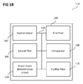
- Figure 1B shows a travel mode determination device 114.
- the travel mode determination device 114 may, similar to the travel mode determination device 100 of Figure 1A , include an inertial sensor 102 (or a plurality of inertial sensors).
- the travel mode determination device 114 may, similar to the travel mode determination device 100 of Figure 1A , further include a first filter 104 configured to filter a first frequency band of an output of the inertial sensor 102.
- the travel mode determination device 114 may, similar to the travel mode determination device 100 of Figure 1A , further include a second filter 106 configured to filter a second frequency band of the output of the inertial sensor 102.
- the travel mode determination device 114 may, similar to the travel mode determination device 100 of Figure 1A , further include a comparator 108 configured to compare a power spectral density of an output of the first filter 104 with a power spectral density of an output of the second filter 106.
- the travel mode determination device 114 may, similar to the travel mode determination device 100 of Figure 1A , further include a travel mode determination circuit 110 configured to determine a travel mode of the travel mode determination device based on an output of the comparator 108.
- the travel mode determination device 114 may further include a further filter 116, like will be described in more detail below.
- the inertial sensor 102, the first filter 104, the second filter 106, the comparator 108, the travel mode determination circuit 110, and the further filter 116 may be coupled with each other, for example via a connection 118, for example an optical connection or an electrical connection, such as for example a cable or a computer bus or via any other suitable electrical connection to exchange electrical signals.
- a connection 118 for example an optical connection or an electrical connection, such as for example a cable or a computer bus or via any other suitable electrical connection to exchange electrical signals.
- the further filter 116 may be configured to filter a further frequency band of the inertial sensor 102.
- the comparator 108 may be configured to compare a power spectral density of the further filter 116 with a at least one of the power spectral density of the first filter 104 or the power spectral density of the second filter 106.
- the further frequency band of the inertial sensor 102 may be a further frequency band of the output of the inertial sensor 102.
- the power spectral density of the further filter 116 may be a power spectral density of an output of the further filter 116.
- the travel mode determination circuit 110 may further be configured to determine the travel mode further based on at least one of the power spectral density of the first filter or the power spectral density of the second filter.
- the travel mode determination circuit 110 may further be configured to determine the travel mode based on at least one of whether the power spectral density of the first filter fulfils a pre-determined criterion or whether the power spectral density of the second filter fulfils a pre-determined criterion.
- the pre-determined criterion may be based on a pre-determined threshold.
- the pre-determined threshold may be determined using a learning method.
- the travel mode determination circuit 110 may further be configured to determine the travel mode further based on at least one of a speed of the travel mode determination device 114, an altitude of the travel mode determination device 114, a brightness of the surrounding of the travel mode determination device 114, a loudness of the surrounding of the travel mode determination device 114.
- a navigation system may be provided, including the travel mode determination device as described above.
- the navigation system may be configured to determine an operation mode based on the determined travel mode.
- a mobile radio communication device including the travel mode determination device as described above.
- the mobile radio communication device may be configured to determine an operation mode based on the determined travel mode.
- a portable device including a navigation system and the travel mode determination device as described above may be provided.
- the portable device may further include: a global navigation satellite subsystem, an inertial navigation subsystem, and a processor; the processor being responsive to signals output by said global navigation satellite subsystem and said inertial navigation subsystem to implement a navigation mode discrimination system for a mode of navigation; wherein said navigation mode discrimination system is arranged to sample the frequency of excitations of signals output from the inertial sensor or sensors and determine one of the navigation modes based on the frequency of excitations of said inertial sensor or sensors.
- the portable device may further include: a sampler to sample the frequency of excitations of signals from the inertial sensor; a low band filter and a high band filter for filtering the inertial frequency sample to a low frequency band sample and a high frequency band sample, a calculator module responsive to each of said low frequency band sample and said high frequency band sample for calculating a low frequency band power spectral density and a high frequency band power spectral density, a comparator configured to compare the low frequency band power spectral density and the high frequency band power spectral density to generate a mode selection signal; and the global navigation satellite subsystem being responsive to the mode selection signal to select one of the navigation modes.
- a sampler to sample the frequency of excitations of signals from the inertial sensor
- a low band filter and a high band filter for filtering the inertial frequency sample to a low frequency band sample and a high frequency band sample
- a calculator module responsive to each of said low frequency band sample and said high frequency band sample for calculating a low frequency band power spectral
- the low frequency band filter may be adapted to filter a low frequency band selected to isolate excitations arising when the device is carried by a pedestrian and the high frequency band filter may be adapted to filter a high frequency band to isolate excitations experienced by the device carried in a motor vehicle.
- the low frequency band filter may be adapted to filter a frequency band between 2Hz and 10Hz and the high frequency band filter is adapted to filter a frequency band between 10Hz and 25Hz.
- a comparator may be arranged to compare the low frequency power spectral density with a first predetermined threshold and where the device is configured to select the road navigation mode when the low frequency power spectral density is smaller than said first threshold.
- a comparator may be arranged to compare the low frequency spectral density with a second predetermined threshold larger than the first threshold, a calculator to calculate a ratio of the low frequency band power spectral density and the high frequency band power spectral density to generate a power spectral density ratio; and a comparator arranged to compare the power spectral density ratio with a high power spectral density ratio threshold; wherein the system is arranged to generate the mode selection signal to select the pedestrian navigation mode when the low frequency spectral density is between the first threshold and the second threshold and the power spectral density ratio exceeds the high spectral density ratio threshold; and the road navigation mode when the power spectral density ratio is less than the high power spectral density ratio.
- a timer may be set to delay a switch from the pedestrian navigation mode to the road navigation mode when the mode discrimination routine responds to the inertial frequency sample to implement a change from the pedestrian navigation mode to the road navigation mode.
- the device may be a communication device.
- Figure 1C shows a flow diagram 120 illustrating a method for controlling a travel mode determination device.
- the travel mode determination device may acquire a signal from an inertial sensor or multiple inertial sensors.
- a first filter of the travel mode determination device may filter a first frequency band of the signal.
- a second filter of the travel mode determination device may filter a second frequency band of the signal.
- a comparator of the travel mode determination device may compare a power spectral density of filtering the first frequency band with a power spectral density of filtering the second frequency band.
- a travel mode determination circuit of the travel mode determination device may determine a travel mode of the travel mode determination device based on the comparing.
- the power spectral density of filtering the first frequency band may be a power spectral density of an output of filtering the first frequency band.
- the power spectral density of filtering the second frequency band may be a power spectral density of an output of filtering the second frequency band.
- the travel mode may include or may be at least one travel mode selected from a list of travel modes consisting of: walking; driving; using a car with a Diesel engine; using a car with a petrol engine; using a car with a gas engine; using an electrical car; using an electrical car in motion; using a bicycle; using a bicycle in motion; using a road of good quality; using a deteriorated road; using a bus; using a train; using a ship; using an airplane; a pedestrian navigation mode; and a road navigation mode.
- the method may further include acquiring a signal (or signals) from at least one further inertial sensor (not shown).
- the inertial sensor (and/ or one or more of the further inertial sensors) may include or may be at least one sensor selected from a list of sensors consisting of: an accelerometer; a one-axis accelerometer; a two-axes accelerometer; a three-axes accelerometer; a gyroscope; a one-axis gyroscope; a two-axes gyroscope; a three-axes gyroscope; and any combination thereof.
- the method may further include: determining a ratio of the power spectral density of filtering the first frequency band and the power spectral density of filtering the second frequency band; and determining the travel mode based on the ratio.
- the method may further include determining the travel mode based on whether the ratio fulfils a pre-determined criterion.
- the pre-determined criterion may be based on a pre-determined threshold.
- the pre-determined threshold may be determined using a learning method
- Filtering the first frequency band may be done (for example using a filter circuit) using a first set of filter parameters.
- Filtering the second frequency band may be done (for example using the (same) filter circuit) using a second set of filter parameters.
- the first frequency band may be a low frequency band.
- the second frequency band may be a high frequency band.
- Filtering the first frequency band may include or may be filtering a low frequency band selected to isolate excitations arising when the travel mode determination device is carried by a pedestrian and the second filtering may include or may be filtering a high frequency band to isolate excitations experienced by the travel mode determination device carried in a motor vehicle.
- the first frequency band may include or may be a frequency band between 2Hz and 10Hz and the second frequency band may include or may be a frequency band between 10Hz and 25Hz.
- the method may further include: comparing a low frequency power spectral density with a first predetermined threshold; and selecting a road navigation mode when the low frequency power spectral density is smaller than said first threshold.
- the method may further include: comparing the low frequency spectral density with a second predetermined threshold larger than the first threshold, calculating a ratio of the low frequency band power spectral density and the high frequency band power spectral density to generate a power spectral density ratio; and comparing the power spectral density ratio with a high power spectral density ratio threshold; generating the mode selection signal to select the pedestrian navigation mode when the low frequency spectral density is between the first threshold and the second threshold and the power spectral density ratio exceeds the high spectral density ratio threshold; and generating the mode selection signal to select the road navigation mode when the power spectral density ratio is less than the high power spectral density ratio.
- the mode selection signal may be generated to select the pedestrian navigation mode.
- the mode selection signal may be generated to select the road navigation mode.
- a timer of the travel mode determination device may be set to delay a switch from the pedestrian navigation mode to the road navigation mode when the mode discrimination routine responds to the inertial frequency sample to implement a change from the pedestrian navigation mode to the road navigation mode.
- the method may further include: filtering a further frequency band of the signal; comparing a power spectral density of filtering the further frequency band with a at least one of the power spectral density of filtering the first frequency band or the power spectral density of filtering the second frequency band.
- the power spectral density of filtering the further frequency band may be a power spectral density of an output of filtering the further frequency band.
- the method may further include: determining the travel mode further based on at least one of the power spectral density of filtering the first frequency band or the power spectral density of filtering the second frequency band.
- the method may further include determining the travel mode based on at least one of whether the power spectral density of filtering the first frequency band fulfils a pre-determined criterion or whether the power spectral density of filtering the second frequency band fulfils a pre-determined criterion.
- the pre-determined criterion may be based on a pre-determined threshold.
- the pre-determined threshold may be determined using a learning method.
- the method may further include: determining the travel mode further based on at least one of a speed of the travel mode determination device, an altitude of the travel mode determination device, a brightness of the surrounding of the travel mode determination device, a loudness of the surrounding of the travel mode determination device.
- a method for controlling a navigation system may include the method for controlling a travel mode determination device described above.
- the navigation system may determine an operation mode based on the determined travel mode.
- a method for controlling a mobile radio communication device may include the method for controlling a travel mode determination device described above.
- the mobile radio communication device may determine an operation mode based on the determined travel mode.
- a navigation process implemented in a portable device having the inertial sensor may include the method for controlling a travel mode determination device described above, and my further include: executing a global navigation satellite routine and an inertial navigation routine, said inertial navigation routine responsive to signals output from the inertial sensor or multiple inertial sensors, and including: a navigation mode discrimination routine including sampling the frequency of excitations of the inertial sensor, and processing the inertial frequency sample to determine a pedestrian navigation mode or a road navigation mode.
- the navigation process may further include: filtering the frequency sample to isolate a low frequency band and a high frequency band; calculating the power spectral densities of the low frequency band and the high frequency band; comparing the power spectral densities of the low frequency band and the high frequency band and; selecting the navigation mode according to the comparison of the power spectral densities of the low frequency band and the high frequency band.
- the low frequency band may isolate excitations arising when the device is carried by a pedestrian, and the high frequency band may isolate excitations experienced as a consequence of the device being carried in a motor vehicle.
- the low frequency band may be in the range 2Hz to 10Hz and the high frequency band may be in the range from 10 Hz to 25 Hz.
- the navigation process may further include: selecting the road navigation mode when the low frequency spectral density is lower than a predetermined first threshold.
- the navigation process may further include: calculating a ratio of the low frequency band power spectral density to the high frequency band power spectral density to generate a power spectral density ratio; selecting the pedestrian navigation mode when the low frequency band power spectral density is between the first and second thresholds and the power spectral density ratio is greater than a high spectral density ratio threshold, and selecting a road navigation mode when the low frequency power spectral density is between the first and second thresholds and the power spectral density ratio is less than the high power spectral density ratio threshold.
- the navigation process may be a process of selecting pedestrian navigation mode when the low frequency spectral density exceeds the second threshold, and the power spectral density ratio is greater than a lower power spectral density ratio threshold; and the navigation process may be a process of selecting road navigation mode when the low frequency spectral density exceeds the second threshold, and the power spectral density ratio is less than the lower power spectral density ratio threshold.
- the discrimination routine selects the road navigation mode from the pedestrian navigation mode the implementation of said road navigation mode is delayed by a timer.
- the navigation process may be implemented in a communication device.
- thresholds have been described with respect to the portable device, they may be applied to any travel mode determination device, for example the travel mode determination device as shown in Figure 1A .
- an integrated global navigation satellite system and inertial navigation system may be provided.
- Various aspects of this disclosure concern the implementation of an integrated global navigation satellite system and inertial navigation systems in a portable mobile device having at least a pedestrian navigation mode and a road vehicle navigation mode.
- the system addresses a problem of navigation mode selection at pedestrian speeds.
- a portable mobile device having a navigation system including: a global navigation satellite subsystem, an inertial navigation subsystem, an inertial sensor or multiple inertial sensors and a processor; the processor being responsive to signals output by said global navigation satellite subsystem and the inertial navigation subsystem to implement a navigation mode discrimination routine for selecting one of a pedestrian navigation mode or a road navigation mode; wherein said mode discrimination includes a sampler to sample the frequency of excitations of the inertial sensor, a low band filter and a high band filter to filter the frequency sample to a low frequency band sample and a high frequency band sample, a calculator module responsive to each of said low frequency band sample and said high frequency band sample to calculate a low band power spectral density and a high band power spectral density; a comparator able to compare the low band power spectral density and the high band power spectral density and to generate a mode selection signal; and the global navigation satellite subsystem
- Various aspects of this disclosure provide a navigation process implemented in a portable mobile device including: executing a global navigation satellite routine and an inertial navigation routine, said inertial navigation routine being responsive to signals output from an inertial sensor or multiple inertial sensors; sampling the frequency of excitations of the inertial sensor; filtering the frequency sample to a low frequency band and a high frequency band; calculating the power spectral density of the low frequency band and the high frequency band; comparing the power spectral density of the low frequency band and the high frequency band; and selecting a navigation mode according to the comparison of the power spectral density of the low frequency band and the high frequency band.
- code adapted for communication via large area network, WiFi, cell phone network or recorded on physical media for execution in a processor in a portable device to implement the process according to various aspects of this disclosure.
- Various aspects of this disclosure relies on the discovery that the frequency of excitations of an inertial sensor carried by a pedestrian, including stationary manipulations of the device, occur typically at a frequency of less than ten hertz, and usually well below ten hertz.
- An inertial sensor conveyed in a device travelling in a vehicle in road mode senses excitations at a frequency typically below twenty five hertz.
- Such road mode inertial excitations are typically induced by vehicle engine motion, road condition, air-conditioning activity, windscreen wiper activity.
- a predominance of excitations in a low frequency band, corresponding to the pedestrian mode will indicate pedestrian mode navigation.
- a predominance of excitations in a high frequency band is indicative of road mode navigation.
- the comparator outputs a signal indicative of pedestrian mode navigation when the low frequency band power spectral density exceeds the high frequency band power spectral density.
- the comparator outputs a signal indicative of road mode navigation when the high frequency band power spectral density exceeds the low frequency band power spectral density.
- dominance may be determined by more complex criteria, to address a condition where each band signal strength is low or there is not much difference. In this condition the dominant frequency band power spectral density may not be the highest frequency band power spectral density.
- the low frequency band is between two and ten hertz and the high frequency band is between ten and twenty five hertz.
- Various aspects of this disclosure also contemplate the possibility of a condition where the power spectral densities of each of the low and high frequency bands are both strongly present.
- This condition may occur where a vehicle passenger or driver is manipulating the device in a slow, or erratically moving vehicle or a vehicle stationary in traffic.
- the difference between the low frequency power spectral density and the high frequency power spectral density may be small.
- the dominant power spectral density may change frequently. Consequently, the mode signal output from the comparator may change frequently over a short time leading to frequent and confusing changes in navigation mode.
- the system and process is set so that the comparison of the power spectral densities may only occur if the low band power spectral density exceeds a predetermined threshold value.
- the comparing may include the calculation of a power spectral density ratio of the low band power spectral density and the high band power spectral density.
- the system will preferably determine pedestrian mode where:
- the higher power spectral density threshold ratio is between 1 and 2, and more preferably 1.5.
- the second low band power spectral density threshold is at least 1.5 times the size of the first low band power spectral density threshold and more preferably twice the size of the first low band power spectral density threshold.
- the lower power spectral density threshold ratio is between 0.5 and 1 and more preferably 0.75.
- the thresholds as described above may be determined by learning, for example using a neural network, or by any other suitable method. Both the absolute as the relative thresholds could be either preconfigured or determined through a learning process or preconfigured and adaptively fine-tuned through using e.g. a neural network or adaptive filters. This learning process could be achieved by getting an independent information about the travel mode. For example, the user may indicate through a control interface, such as a GUI (graphical user interface) the travel mode (pedestrian or road, including specification of submodes i.e. pedestrian walking, pedestrian running, ). Other independent sources e.g. derived from device usage, traveled roads (as will be explained below) or whether the device is mounted on a dashboard may also be utilized.
- a control interface such as a GUI (graphical user interface) the travel mode (pedestrian or road, including specification of submodes i.e. pedestrian walking, pedestrian running, ).
- submodes i.e. pedestrian walking, pedestrian running, .
- Other independent sources e.g
- the power spectral densities of the different bands are assessed and averaged during the learning period, after which a routine could be used to establish the most appropriate thresholds, making optimal use of the headroom in power spectral densities and power spectral density ratios between the combined sets of power spectral densities and power spectral density ratios obtained for the different learned travel modes.
- the determination of threshold parameters through learning should include a level of hysteresis for algorithmic robustness reasons.
- Conditions (a) and (b) indicate that the pedestrian is walking.
- Conditions (c) and (d) indicate that the pedestrian is running.
- a delay timer may be provided to delay cancellation of the pedestrian mode, and consequent switching to the road mode.
- the delay timer may be implemented when the low frequency band power spectral density falls briefly below a large fraction of the first low frequency band power spectral density threshold, but continues to exceed the high frequency band power spectral density.
- the large fraction may be 80% of the threshold at (a).
- the timer may be provided by a countdown timer which may count down from a preset timer value which may be 512 (the period assumed here may be 20 ms (based on a sampling rate of 50 Hz)).
- the counter may be decremented by one for each sequential cycle of the process that the low band power spectral density remains at less than 80% of the threshold value.
- the timer may be reset, preferably by resetting the countdown timer to its initial value, for example 512.
- the device and process may distinguish between the user manipulating a device while walking and the user manipulating the device while in a car.
- the device and process may distinguish between distinguish between a pedestrian carrying and manipulating the device while walking at low speed and a device fixed in a road vehicle travelling at low speed or stationary in congested traffic.
- the load on the device processor imposed by the execution of the process is constant (the underlying reason may be that power spectral densities are calculated based on a sliding FFT (fast Fourier transform)).
- a cell phone or similar portable device includes a global navigation satellite subsystem and an inertial navigation subsystem responsive to an inertial sensor.
- the inertial sensor is used in a navigation mode discrimination routine to sample the frequency of inertial disturbances of the device and the sampled frequencies are processed to determine if the device is being carried by a pedestrian or carried in a vehicle. By reliably determining the mode of transport, erroneous navigation can be avoided.
- a portable device including a navigation system may include: a global navigation satellite subsystem, an inertial navigation subsystem, an inertial sensor and a processor; the processor being responsive to signals output by said global navigation satellite subsystem and said inertial navigation subsystem to implement a navigation mode discrimination system for selecting one of a pedestrian navigation mode or a road navigation mode; wherein said navigation mode discrimination system is arranged to sample the frequency of excitations of the inertial sensor (6) and determine one of the navigation modes based on the frequency of excitations of said inertial sensor (6).
- the device may include: a sampler to sample the frequency of excitations of the inertial sensor; a low band filter and a high band filter for filtering the inertial frequency sample to a low frequency band sample and a high frequency band sample; a calculator module responsive to each of said low frequency band sample and said high frequency band sample for calculating a low frequency band power spectral density and a high frequency band power spectral density; a comparator configured to compare the low frequency band power spectral density and the high frequency band power spectral density to generate a mode selection signal; and the global navigation satellite subsystem being responsive to the mode selection signal to select one of the navigation modes.
- the low frequency band filter may be adapted to filter a low frequency band selected to isolate excitations arising when the device is carried by a pedestrian and the high frequency band filter may be adapted to filter a high frequency band to isolate excitations experienced by the device carried in a motor vehicle.
- the low frequency band filter may be adapted to filter a frequency band between 2Hz and 10Hz and the high frequency band filter is adapted to filter a frequency band between 10Hz and 25Hz.
- a comparator may be arranged to compare the low frequency power spectral density with a first predetermined threshold and where the device is configured to select the road navigation mode when the low frequency power spectral density is smaller than said first threshold.
- a comparator may be arranged to compare the low frequency spectral density with a second predetermined threshold larger than the first threshold, a calculator to calculate a ratio of the low frequency band power spectral density and the high frequency band power spectral density to generate a power spectral density ratio; and a comparator arranged to compare the power spectral density ratio with a high power spectral density ratio threshold; wherein the system may be arranged to generate the mode selection signal to select the pedestrian navigation mode when the low frequency spectral density is between the first threshold and the second threshold and the power spectral density ratio exceeds the high spectral density ratio threshold; and the road navigation mode when the power spectral density ratio is less than the high power spectral density ratio.
- the system may be arranged so that when: the low frequency spectral density exceeds the second threshold, and the power spectral density ratio is greater than a lower spectral density ratio threshold, the mode selection signal is generated to select the pedestrian navigation mode; and the low frequency spectral density exceeds the second threshold, and the power spectral density ratio is less than the lower spectral density ratio threshold the mode selection signal is generated to select the road navigation mode.
- a timer may be set to delay a switch from the pedestrian navigation mode to the road navigation mode when the mode discrimination routine responds to the inertial frequency sample to implement a change from the pedestrian navigation mode to the road navigation mode.
- the device may be a communication device.
- a navigation process implemented in a portable device having an inertial sensor or multiple inertial sensors (6) may include: executing a global navigation satellite routine and an inertial navigation routine, said inertial navigation routine responsive to signals output from the inertial sensor, and including: a navigation mode discrimination routine may include sampling the frequency of excitations of the inertial sensor, and processing the inertial frequency sample to determine a pedestrian navigation mode or a road navigation mode.
- the navigation process may include: filtering the frequency sample to isolate a low frequency band and a high frequency band: calculating the power spectral density of the low frequency band and the high frequency band; comparing the power spectral density of the low frequency band and the high frequency band and; selecting the navigation mode according to the comparison of the power spectral density of the low frequency band and the high frequency band.
- the low frequency band may isolate excitations arising when the device is carried by a pedestrian, and the high frequency band may isolate excitations experienced as a consequence of the device being carried in a motor vehicle.
- the low frequency band may be in the range 2Hz to 10Hz and the high frequency band may be in the range from 10 Hz to 25 Hz.
- the process may further include selecting the road navigation mode when the low frequency spectral density is lower than a predetermined first threshold.
- the process may include: calculating a ratio of the low frequency band power spectral density to the high frequency band power spectral density to generate a power spectral density ratio; selecting the pedestrian navigation mode when the low frequency band power spectral density is between the first and second thresholds and the power spectral density ratio is greater than a high spectral density ratio threshold; and selecting a road navigation mode when the low frequency power spectral density is between the first and second thresholds and the power spectral density ratio is less than the high power spectral density ratio threshold.
- a process may be a process of selecting pedestrian navigation mode when the low frequency spectral density exceeds the second threshold, and the power spectral density ratio is greater than a lower power spectral density ratio threshold; and of selecting road navigation mode when the low frequency spectral density exceeds the second threshold, and the power spectral density ratio is less than the lower power spectral density ratio threshold.
- the discrimination routine selects the road navigation mode from the pedestrian navigation mode the implementation of said road navigation mode may be delayed by a timer.
- the process may be implemented in a communication device.
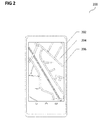
- Figure 2 shows a device 200 in the form of a cell phone 202 while executing a global navigation satellite application resulting in the display of a relevant map 204 on a touch screen 206.
- the cell phone 300 incorporates a processor 304 arranged to process data supplied from the touch screen 302 or received from an antenna 308 in accordance with instructions executing from machine readable code recorded in a memory 306.
- the cell phone 300 may further include a speaker 310.
- the cell phone 202 (shown in Figure 2 ) or 300 may interface with the user via the touch screen to receive instructions and to display the instant location of the cell phone and a route to a destination to which the user wishes to navigate.
- the route may include roads from which pedestrians are excluded and footpaths from which vehicular traffic is excluded. To optimize the route it is therefore important that the cell phone 1 selects the route for navigation in accordance with the mode of travel, in this case the modes are pedestrian or road modes.
- the cell phone 202 may include a global positioning system (GPS) antenna 402 able to receive global positioning system radio GPS signals from satellites in known fashion.
- GPS global positioning system
- GNSS global navigation satellite subsystem
- Processing of the cell phone 202 will be described with respect to Figure 5 , in which processing starts at 504, and a GPS signal 502 may be input.
- An inertial sensor in the form of an accelerometer 406 may be included in cell phone 202 which is sensitive to accelerations of the cell phone 202.
- signals from the inertial sensor may be processed by an inertial navigation subsystem 408 and used to calculate the speed and heading of the cell phone at 508.
- the speed calculated from the inertial sensor is incompatible with a pedestrian speed for example a speed in excess of 21km/h, the cell phone may implement a road navigation mode in GNSS 404. However, if the speed calculated at 508 is a possible pedestrian speed the process implements a navigation mode discrimination routine at 510.
- the mode discrimination routine may sample the frequency of excitations of the inertial sensor 406 at sampler 410 at 512 and may filter sample through low band pass filter 414 and high band pass filter 414 at 514 and 516 respectively.
- the low band pass filter may filter signals between 2Hz and 10Hz while the high band pass filter may filter between 10 Hz and 25 Hz.
- the low band signal may be supplied to a low frequency band calculator 416 which may calculate the low frequency band power spectral density (PSD1) at 518.
- the high frequency band signal may be used by calculator 418 at 520 to calculate a high frequency band power spectral density (PSD2).
- a calculator may calculate the ratio of the low frequency power spectral density (PSD1) to the high frequency power spectral density (PSD2) to generate the power spectral density ratio (PSDR).
- the calculator may generate a navigation mode selection signal based solely on whether or not the PSDR is greater than or less than one. If the PSDR is greater than one, the low frequency excitations are dominant and the pedestrian mode should be selected. If the PSDR is less than one, the high frequency excitations are dominant and the road navigation mode is selected. However, this may not deal well with situations where each signal is weak or the power spectral densities are close in value.
- the process may go to 524 where the low frequency band power spectral density is compared with a first threshold. If the low frequency power spectral density is less than the first threshold value, the process generates a navigation mode selection signal causing selection of the road mode for navigation.
- the low frequency band power spectral density is compared to a second threshold, which in this case is the double threshold at 526.
- the term "double threshold" is used to indicate the value of the first threshold multiplied by a factor 2.
- the power spectral density ratio is compared to a high spectral density ratio threshold in 528.
- the high spectral density ratio threshold is 1.5 times the value of the first threshold to determine if the low frequency excitations are dominant.
- the system and process determines that the device is being carried by a pedestrian.
- the pedestrian mode selection signal is generated accordingly and the GNSS subsystem responds to implement a pedestrian navigation mode at 530.
- 534 compares the power spectral density ratio to a lower power spectral density threshold ratio.
- the lower power spectral density ratio threshold may be 0.75. If the lower power spectral density ratio threshold is not exceeded, the process goes to 532 where a road mode selection signal is generated and the GNSS responds to implement road navigation. If the lower power spectral density ratio threshold is exceeded, the process causes the system to generate a pedestrian mode selection signal which causes the GNSS subsystem to implement the pedestrian navigation mode at 530.
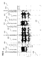
- Figure 6 is a chart 600 of an inertial sensor excitation sample taken during a combined pedestrian and road navigation with time plotted on the X axis (horizontal axis) increasing from left to right and the excitations in low and high frequency bands plotted on the Y axis (vertical axis).
- the devices lies on a desk during period 602.
- a user of the device walks to a car during period 604, and fixes the handset in 606, drives in 608, performs a voice call during driving in 610, continues driving in 612, stops in 614, is at a filling station in 616, fixes the devices in 618, drives in 620, picks the device to go home in 622, and walks home in 624, like will be described in more detail below.
- a horizontal axis indicates time, and a vertical axis 628 indicates acceleration (expressed in mg).
- Three lines show the excitations of the accelerometer along its native 3 axes.
- a dotted line 634 indicates the x-axis, a dashed line with crosses 630 indicates the y-axis, and a solid line without crosses 632 indicates the z-axis.
- Figure 7 shows an illustration 700 of the power spectral density plotted on the Y axis (vertical axis 704) with time on the X axis (horizontal axis 702) in the upper graph in Figure 7 .
- a PSD2 value (corresponding to high frequency power spectral density, as described above is illustrated by a solid line706, and a PSD1 value (corresponding to low frequency power spectral density, as described above) is illustrated by a dotted line 710.
- PSD1 may correspond to the frequency band between 2 and 10 Hz
- PSD2 may correspond to the frequency band between 10 and 25 Hz.
- a state is illustrated by a dashed line 708, wherein 0 means road state, 1000 means pedestrian state, and 500 means unknown state.
- the vertical axis 712 indicates a counter value, and a counter value (illustrated by a solid line 714) over time (as indicated by the horizontal axis 702) is illustrated.
- the counter value may correspond to the delay timer as described above.
- the cell phone In the first period P1 (602) the cell phone is lying on a desk and is immobile. Little or no excitation of either low or high frequency band is detected.
- the cell phone 202 is carried to the car by a walking user.
- the power spectral density of the low frequency band greatly exceeds the high frequency band power spectral density indicative of pedestrian travel, if GNSS navigation was activated, pedestrian mode would readily be identified and selected by the process.
- the user fixes the cell phone into a dashboard mounting.
- the recording shows each of low and high frequency excitations in relatively similar amounts as the cell phone is manipulated.
- the criteria at 524 requiring the low frequency power spectral density to exceed a minimum threshold to stop pedestrian mode selection results in road mode selection although the high frequency power spectral density is lower than the low frequency power spectral density in the third period.
- the vehicle engine is started and the vehicle driven away.
- the high frequency power spectral density rises quickly to greatly exceed the low frequency power spectral density ensuring that at any speed, road mode navigation is selected.
- road mode navigation frequent rapid changes of heading are blocked in the GNSS.
- the cell phone is handled by the user picking up a cell phone call. As shown in Figure 6 , this results in considerable excitation in the high frequency band which can include rapid changes of direction unconnected with the overall motion of the vehicle. However, the high frequency power spectral density remains dominant in Figure 7 and no change of navigation mode will occur. As before, maintenance of the road navigation mode blocks rapid changes in heading in the GNSS.
- the sixth period P6 (612) is substantially similar to the fourth period of driving.
- the vehicle comes to a halt at a fuel station and the user exits the vehicle during eighth period P8 (616) and undertakes pedestrian activities.
- the low frequency power spectral density is clearly dominant over the high frequency power spectral density and the cell phone would switch to pedestrian mode navigation.
- the ninth period P9 (618) activity is essentially similar to the third period P3 (606) as the user returns to the vehicle, remounts the cell phone and drives away at period P10 (620).
- the low frequency power spectral density rises to dominate the high frequency power spectral density and the cell phone switches to pedestrian navigation mode.
- cell phones, personal digital assistants and dedicated man portable global navigation satellite system devices commonly incorporate an inertial sensor and can therefore be adapted to implement the components and process described above by loading and/or updating code to execute in a processor of the device.
- the code to implement the process may be loaded onto device memory via a USB port, bluetooth, WiFi, GSM or other compatible technologies for recordal in a device memory and execution on the device processor.
- Example 1 is a travel mode determination device comprising: an inertial sensor; a first filter configured to filter a first frequency band of the inertial sensor; a second filter configured to filter a second frequency band of the inertial sensor; a comparator configured to compare a power spectral density of the first filter with a power spectral density of the second filter; and a travel mode determination circuit configured to determine a travel mode of the travel mode determination device based on the comparator.
- the subject-matter of example 1 can optionally include that the first frequency band of the inertial sensor is a first frequency band of an output of the inertial sensor; that the second frequency band of the inertial sensor is a second frequency band of an output of the inertial sensor; that the power spectral density of the first filter is a power spectral density of an output of the first filter; that the power spectral density of the second filter is a power spectral density of an output of the second filter; and that the travel mode determination circuit is configured to determine the travel mode of the travel mode determination device based on an output of the comparator.
- the subject-matter of example 1 or 2 can optionally include at least one further inertial sensor.
- the subject-matter of any one of examples 1 to 3 can optionally include that the inertial sensor comprises at least one sensor selected from a list of sensors consisting of: an accelerometer; a one-axis accelerometer; a two-axes accelerometer; a three-axes accelerometer; a gyroscope; a one-axis gyroscope; a two-axes gyroscope; a three-axes gyroscope; and any combination thereof.
- the subject-matter of any one of examples 1 to 4 can optionally include that the travel mode comprises at least one travel mode selected from a list of travel modes consisting of: walking; driving; using a car with a Diesel engine; using a car with a petrol engine; using a car with a gas engine; using an electrical car; using an electrical car in motion; using a bicycle; using a bicycle in motion; using a road of good quality; using a deteriorated road; using a bus; using a train; using a ship; using an airplane; a pedestrian navigation mode; and a road navigation mode.
- the travel mode comprises at least one travel mode selected from a list of travel modes consisting of: walking; driving; using a car with a Diesel engine; using a car with a petrol engine; using a car with a gas engine; using an electrical car; using an electrical car in motion; using a bicycle; using a bicycle in motion; using a road of good quality; using a deteriorated road; using a bus; using a train;
- the subject-matter of any one of examples 1 to 5 can optionally include that the comparator is configured to determine a ratio of the power spectral density of the first filter and the power spectral density of the second filter; and that the travel mode determination circuit is configured to determine the travel mode based on the ratio.
- the subject-matter of example 6 can optionally include that the travel mode determination circuit is further configured to determine the travel mode based on whether the ratio fulfils a pre-determined criterion.
- the subject-matter of example 7 can optionally include that the pre-determined criterion is based on a pre-determined threshold.
- the subject-matter of example 8 can optionally include that the pre-determined threshold is determined using a learning method.
- the subject-matter of any one of examples 1 to 9 can optionally include that the first filter comprises a filter circuit using a first set of filter parameters; and that the second filter comprises the filter circuit using a second set of filter parameters.
- the subject-matter of any one of examples 1 to 10 can optionally include that the first frequency band is a low frequency band.
- the subject-matter of any one of examples 1 to 11 can optionally include that the second frequency band is a high frequency band.
- the subject-matter of any one of examples 1 to 12 can optionally include that the first frequency band is a low frequency band; and that the second frequency band is a high frequency band.
- the subject-matter of example 13 can optionally include that the first filter is configured to filter a low frequency band selected to isolate excitations arising when the travel mode determination device is carried by a pedestrian and the second filter is configured to filter a high frequency band to isolate excitations experienced by the travel mode determination device carried in a motor vehicle.
- the subject-matter of example 13 or 14 can optionally include that the first filter is configured to filter a frequency band between 2Hz and 10Hz and the second filter is configured to filter a frequency band between 10Hz and 25Hz.
- the subject-matter of any one of examples 13 to 15 can optionally include that the comparator is configured to compare a low frequency power spectral density with a first predetermined threshold and where the travel mode determination device is configured to select a road navigation mode when the low frequency power spectral density is smaller than said first threshold.
- the subject-matter of example 16 can optionally include that the comparator is configured to compare the low frequency spectral density with a second predetermined threshold larger than the first threshold, and that the travel mode determination device further comprises a calculator configured to calculate a ratio of the low frequency band power spectral density and the high frequency band power spectral density to generate a power spectral density ratio; and a comparator arranged to compare the power spectral density ratio with a high power spectral density ratio threshold; and that the travel mode determination device is configured to generate the mode selection signal to select the pedestrian navigation mode when the low frequency spectral density is between the first threshold and the second threshold and the power spectral density ratio exceeds the high spectral density ratio threshold; and that the travel mode determination device is configured to generate the mode selection signal to select the road navigation mode when the power spectral density ratio is less than the high power spectral density ratio.
- the subject-matter of example 17 can optionally include that the travel mode determination device is arranged so that: when the low frequency spectral density exceeds the second threshold, and when the power spectral density ratio is greater than a lower spectral density ratio threshold, the mode selection signal is generated to select the pedestrian navigation mode; and when the low frequency spectral density exceeds the second threshold, and when the power spectral density ratio is less than the lower spectral density ratio threshold the mode selection signal is generated to select the road navigation mode.
- the subject-matter of any one of examples 13 to 18 can optionally include that a timer is set to delay a switch from the pedestrian navigation mode to the road navigation mode when the mode discrimination routine responds to the inertial frequency sample to implement a change from the pedestrian navigation mode to the road navigation mode.
- the subject-matter of any one of examples 1 to 18 can optionally include a further filter configured to filter a further frequency band of the inertial sensor; wherein the comparator is configured to compare a power spectral density of the further filter with a at least one of the power spectral density of the first filter or the power spectral density of the second filter.
- the subject-matter of example 20 can optionally further include that the further frequency band of the inertial sensor is a further frequency band of the output of the inertial sensor; and that that the power spectral density of the further filter is a power spectral density of an output of the further filter.
- the subject-matter of any one of examples 1 to 20 can optionally include that the travel mode determination circuit is further configured to determine the travel mode further based on at least one of the power spectral density of the first filter or the power spectral density of the second filter.
- the subject-matter of example 22 can optionally include that the travel mode determination circuit is further configured to determine the travel mode based on at least one of whether the power spectral density of the first filter fulfils a pre-determined criterion or whether the power spectral density of the second filter fulfils a pre-determined criterion.
- the subject-matter of example 23 can optionally include that the pre-determined criterion is based on a pre-determined threshold.
- the subject-matter of example 24 can optionally include that the pre-determined threshold is determined using a learning method.
- the subject-matter of any one of examples 1 to 25 can optionally include that the travel mode determination circuit is further configured to determine the travel mode further based on at least one of a speed of the travel mode determination device, an altitude of the travel mode determination device, a brightness of the surrounding of the travel mode determination device, a loudness of the surrounding of the travel mode determination device.
- Example 27 is a navigation system comprising the travel mode determination device of any one of examples 1 to 26, wherein the navigation system is configured to determine an operation mode based on the determined travel mode.
- Example 28 is a mobile radio communication device comprising the travel mode determination device of any one of examples 1 to 26, wherein the mobile radio communication device is configured to determine an operation mode based on the determined travel mode.
- Example 29 is a portable device including a navigation system and the travel mode determination device of any one of examples 1 to 26, the portable device further comprising: a global navigation satellite subsystem, an inertial navigation subsystem, and a processor; the processor being responsive to signals output by said global navigation satellite subsystem and said inertial navigation subsystem to implement a navigation mode discrimination system for a mode of navigation; wherein said navigation mode discrimination system is arranged to sample the frequency of excitations of signals output from the inertial sensor and determine one of the navigation modes based on the frequency of excitations of said inertial sensor.
- the subject-matter of example 29 can optionally include: a sampler to sample the frequency of excitations of signals from the inertial sensor; a low band filter and a high band filter configured to filter the inertial frequency sample to a low frequency band sample and a high frequency band sample, a calculator module responsive to each of said low frequency band sample and said high frequency band sample configured to calculate a low frequency band power spectral density and a high frequency band power spectral density; a comparator configured to compare the low frequency band power spectral density and the high frequency band power spectral density to generate a mode selection signal; and the global navigation satellite subsystem being responsive to the mode selection signal to select one of the navigation modes.
- the subject-matter of example 29 or 30 can optionally include that the low frequency band filter is adapted to filter a low frequency band selected to isolate excitations arising when the device is carried by a pedestrian and the high frequency band filter is adapted to filter a high frequency band to isolate excitations experienced by the device carried in a motor vehicle.
- the subject-matter of example 31 can optionally include that the low frequency band filter is adapted to filter a frequency band between 2Hz and 10Hz and the high frequency band filter is adapted to filter a frequency band between 10Hz and 25Hz.
- the subject-matter of any one of examples 30 to 32 can optionally include that a comparator is arranged to compare the low frequency power spectral density with a first predetermined threshold and where the device is configured to select the road navigation mode when the low frequency power spectral density is smaller than said first threshold.
- the subject-matter of example 33 can optionally include that a comparator is arranged to compare the low frequency spectral density with a second predetermined threshold larger than the first threshold, a calculator to calculate a ratio of the low frequency band power spectral density and the high frequency band power spectral density to generate a power spectral density ratio; and a comparator arranged to compare the power spectral density ratio with a high power spectral density ratio threshold; wherein the system is arranged to generate the mode selection signal to select the pedestrian navigation mode when the low frequency spectral density is between the first threshold and the second threshold and the power spectral density ratio exceeds the high spectral density ratio threshold; and the road navigation mode when the power spectral density ratio is less than the high power spectral density ratio.
- the subject-matter of example 34 can optionally include that the system is arranged so that when: the low frequency spectral density exceeds the second threshold, and the power spectral density ratio is greater than a lower spectral density ratio threshold, the mode selection signal is generated to select the pedestrian navigation mode; and the low frequency spectral density exceeds the second threshold, and the power spectral density ratio is less than the lower spectral density ratio threshold the mode selection signal is generated to select the road navigation mode.
- the subject-matter of any one of examples 29 to 35 can optionally include that a timer is set to delay a switch from the pedestrian navigation mode to the road navigation mode when the mode discrimination routine responds to the inertial frequency sample to implement a change from the pedestrian navigation mode to the road navigation mode.
- the subject-matter of any one of examples 29 to 36 can optionally include that the device is a communication device.
- Example 38 is a method for controlling a travel mode determination device comprising: acquiring a signal from an inertial sensor; filtering a first frequency band of the signal; filtering a second frequency band of the signal; comparing a power spectral density of filtering the first frequency band with a power spectral density of filtering the second frequency band; and determining a travel mode of the travel mode determination device based on the comparing.
- the subject-matter of example 38 can optionally include that the power spectral density of filtering the first frequency band is a power spectral density of an output of filtering the first frequency band; and that the power spectral density of filtering the second frequency band is a power spectral density of an output of filtering the second frequency band.
- the subject-matter of example 38 or 39 can optionally include acquiring signals from at least one further inertial sensor.
- the subject-matter of any one of examples 38 to 40 can optionally include that the inertial sensor comprises at least one sensor selected from a list of sensors consisting of: an accelerometer; a one-axis accelerometer; a two-axes accelerometer; a three-axes accelerometer; a gyroscope; a one-axis gyroscope; a two-axes gyroscope; a three-axes gyroscope; and any combination thereof.
- the subject-matter of any one of examples 38 to 41 can optionally include that the travel mode comprises at least one travel mode selected from a list of travel modes consisting of: walking; driving; using a car with a Diesel engine; using a car with a petrol engine; using a car with a gas engine; using an electrical car; using an electrical car in motion; using a bicycle; using a bicycle in motion; using a road of good quality; using a deteriorated road; using a bus; using a train; using a ship; using an airplane; a pedestrian navigation mode; and a road navigation mode.
- the travel mode comprises at least one travel mode selected from a list of travel modes consisting of: walking; driving; using a car with a Diesel engine; using a car with a petrol engine; using a car with a gas engine; using an electrical car; using an electrical car in motion; using a bicycle; using a bicycle in motion; using a road of good quality; using a deteriorated road; using a bus; using a train;
- the subject-matter of any one of examples 38 to 42 can optionally include: determining a ratio of the power spectral density of filtering the first frequency band and the power spectral density of filtering the second frequency band; and determining the travel mode based on the ratio.
- the subject-matter of example 43 can optionally include: determining the travel mode based on whether the ratio fulfils a pre-determined criterion.
- the subject-matter of example 44 can optionally include that the pre-determined criterion is based on a pre-determined threshold.
- the subject-matter of example 45 can optionally include that the pre-determined threshold is determined using a learning method.
- the subject-matter of any one of examples 38 to 46 can optionally include that filtering the first frequency band is done using a first set of filter parameters; and that filtering the second frequency band is done using a second set of filter parameters.
- the subject-matter of any one of examples 38 to 47 can optionally include that the first frequency band is a low frequency band.
- the subject-matter of any one of examples 38 to 48 can optionally include that the second frequency band is a high frequency band;
- the subject-matter of any one of examples 38 to 49 can optionally include that the first frequency band is a low frequency band; and that the second frequency band is a high frequency band;
- the subject-matter of example 50 can optionally include that filtering the first frequency band comprises filtering a low frequency band selected to isolate excitations arising when the travel mode determination device is carried by a pedestrian and the second filtering is configured to filter a high frequency band to isolate excitations experienced by the travel mode determination device carried in a motor vehicle.
- the subject-matter of example 50 or 51 can optionally include that the first frequency band comprises a frequency band between 2Hz and 10Hz and the second frequency band comprises a frequency band between 10Hz and 25Hz.
- the subject-matter of any one of examples 50 to 52 can optionally include: comparing a low frequency power spectral density with a first predetermined threshold; and selecting a road navigation mode when the low frequency power spectral density is smaller than said first threshold.
- the subject-matter of example 53 can optionally include: comparing the low frequency spectral density with a second predetermined threshold larger than the first threshold; calculating a ratio of the low frequency band power spectral density and the high frequency band power spectral density to generate a power spectral density ratio; and comparing the power spectral density ratio with a high power spectral density ratio threshold; generating the mode selection signal to select the pedestrian navigation mode when the low frequency spectral density is between the first threshold and the second threshold and the power spectral density ratio exceeds the high spectral density ratio threshold; and generating the mode selection signal to select the road navigation mode when the power spectral density ratio is less than the high power spectral density ratio.
- the subject-matter of example 54 can optionally include that when the low frequency spectral density exceeds the second threshold, and when the power spectral density ratio is greater than a lower spectral density ratio threshold, the mode selection signal is generated to select the pedestrian navigation mode; and when the low frequency spectral density exceeds the second threshold, and when the power spectral density ratio is less than the lower spectral density ratio threshold the mode selection signal is generated to select the road navigation mode.
- the subject-matter of any one of examples 50 to 55 can optionally include that a timer is set to delay a switch from the pedestrian navigation mode to the road navigation mode when the mode discrimination routine responds to the inertial frequency sample to implement a change from the pedestrian navigation mode to the road navigation mode.
- the subject-matter of any one of examples 38 to 56 can optionally include: filtering a further frequency band of the signal; comparing a power spectral density of filtering the further frequency band with a at least one of the power spectral density of filtering the first frequency band or the power spectral density of filtering the second frequency band.
- the subject-matter of example 57 can optionally include that the power spectral density of filtering the further frequency band is a power spectral density of an output of filtering the further frequency band.
- the subject-matter of any one of examples 38 to 58 can optionally include: determining the travel mode further based on at least one of the power spectral density of filtering the first frequency band or the power spectral density of filtering the second frequency band.
- the subject-matter of example 59 can optionally include: determining the travel mode based on at least one of whether the power spectral density of filtering the first frequency band fulfils a pre-determined criterion or whether the power spectral density of filtering the second frequency band fulfils a pre-determined criterion.
- the subject-matter of example 60 can optionally include that the pre-determined criterion is based on a pre-determined threshold.
- the subject-matter of example 61 can optionally include that the pre-determined threshold is determined using a learning method.
- the subject-matter of any one of examples 38 to 62 can optionally include: determining the travel mode further based on at least one of a speed of the travel mode determination device, an altitude of the travel mode determination device, a brightness of the surrounding of the travel mode determination device, a loudness of the surrounding of the travel mode determination device.
- Example 64 is a method for controlling a navigation system comprising the method of any one of examples 38 to 63, wherein the navigation system determines an operation mode based on the determined travel mode.
- Example 65 is a method for controlling a mobile radio communication device comprising the method of any one of examples 38 to 63, wherein the mobile radio communication device determines an operation mode based on the determined travel mode.
- Example 66 is a navigation process implemented in a portable device having the inertial sensor comprising the method of any one of examples 38 to 63 further comprising: executing a global navigation satellite routine and an inertial navigation routine, said inertial navigation routine responsive to signals output from the inertial sensor, and including: a navigation mode discrimination routine comprising sampling the frequency of excitations of the inertial sensor, and processing the inertial frequency sample to determine a pedestrian navigation mode or a road navigation mode.
- the subject-matter of example 66 can optionally include: filtering the frequency sample to isolate a low frequency band and a high frequency band; calculating the power spectral density of the low frequency band and the high frequency band; comparing the power spectral density of the low frequency band and the high frequency band and; selecting the navigation mode according to the comparison of the power spectral density of the low frequency band and the high frequency band.
- the subject-matter of example 66 or 67 can optionally include that the low frequency band isolates excitations arising when the device is carried by a pedestrian, and the high frequency band isolates excitations experienced as a consequence of the device being carried in a motor vehicle.
- the subject-matter of example 67 or 68 can optionally include that the low frequency band is in the range 2Hz to 10Hz and the high frequency band is in the range from 10 Hz to 25 Hz.
- the subject-matter of any one of examples 67 to 69 can optionally include: selecting the road navigation mode when the low frequency spectral density is lower than a predetermined first threshold.
- the subject-matter of any one of examples 67 to 70 can optionally include: calculating a ratio of the low frequency band power spectral density to the high frequency band power spectral density to generate a power spectral density ratio; selecting the pedestrian navigation mode when the low frequency band power spectral density is between the first and second thresholds and the power spectral density ratio is greater than a high spectral density ratio threshold, and selecting a road navigation mode when the low frequency power spectral density is between the first and second thresholds and the power spectral density ratio is less than the high power spectral density ratio threshold.
- the subject-matter of any one of examples 66 to 71 can optionally be a method of selecting pedestrian navigation mode when the low frequency spectral density exceeds the second threshold, and the power spectral density ratio is greater than a lower power spectral density ratio threshold; and selecting road navigation mode when the low frequency spectral density exceeds the second threshold, and the power spectral density ratio is less than the lower power spectral density ratio threshold.
- the subject-matter of any one of examples 66 to 72 can optionally include that when the discrimination routine selects the road navigation mode from the pedestrian navigation mode the implementation of said road navigation mode is delayed by a timer.
- the subject-matter of any one of examples 66 to 73 can optionally include that it is implemented in a communication device.
- Example 75 is a travel mode determination device comprising: an inertial sensor means; a first filter means for filtering a first frequency band of the inertial sensor; a second filter means for filtering a second frequency band of the inertial sensor; a comparator means for comparing a power spectral density of the first filter with a power spectral density of the second filter; and a travel mode determination means for determining a travel mode of the travel mode determination device based on the comparator.
- the subject-matter of example 75 can optionally include that the first frequency band of the inertial sensor means is a first frequency band of an output of the inertial sensor means; that the second frequency band of the inertial sensor means is a second frequency band of an output of the inertial sensor means; that the power spectral density of the first filter means is a power spectral density of an output of the first filter means; that the power spectral density of the second filter means is a power spectral density of an output of the second filter means; and that the travel mode determination means is for determining the travel mode of the travel mode determination device based on an output of the comparator means.
- the subject-matter of example 75 or 76 can optionally include: at least one further inertial sensor means.
- the subject-matter of any one of examples 75 to 77 can optionally include that the inertial sensor means comprises at least one sensor selected from a list of sensors consisting of: an accelerometer; a one-axis accelerometer; a two-axes accelerometer; a three-axes accelerometer; a gyroscope; a one-axis gyroscope; a two-axes gyroscope; a three-axes gyroscope; and any combination thereof.
- the subject-matter of any one of examples 75 to 78 can optionally include that the travel mode comprises at least one travel mode selected from a list of travel modes consisting of: walking; driving; using a car with a Diesel engine; using a car with a petrol engine; using a car with a gas engine; using an electrical car; using an electrical car in motion; using a bicycle; using a bicycle in motion; using a road of good quality; using a deteriorated road; using a bus; using a train; using a ship; using an airplane; a pedestrian navigation mode; and a road navigation mode.
- the travel mode comprises at least one travel mode selected from a list of travel modes consisting of: walking; driving; using a car with a Diesel engine; using a car with a petrol engine; using a car with a gas engine; using an electrical car; using an electrical car in motion; using a bicycle; using a bicycle in motion; using a road of good quality; using a deteriorated road; using a bus; using a train
- the subject-matter of any one of examples 75 to 76 can optionally include that the comparator means is for determining a ratio of the power spectral density of the first filter means and the power spectral density of the second filter means; and that the travel mode determination means is for determining the travel mode based on the ratio.
- the subject-matter of example 80 can optionally include that the travel mode determination means is further for determining the travel mode based on whether the ratio fulfils a pre-determined criterion.
- the subject-matter of example 81 can optionally include that the pre-determined criterion is based on a pre-determined threshold.
- the subject-matter of example 82 can optionally include that the pre-determined threshold is determined using a learning method.
- the subject-matter of any one of examples 75 to 83 can optionally include that that the first filter means comprises a filter circuit using a first set of filter parameters; and that the second filter means comprises the filter circuit using a second set of filter parameters.
- the subject-matter of any one of examples 75 to 84 can optionally include that the first frequency band is a low frequency band;
- the subject-matter of any one of examples 75 to 85 can optionally include that the second frequency band is a high frequency band;
- the subject-matter of any one of examples 75 to 86 can optionally include that the first frequency band is a low frequency band; and that the second frequency band is a high frequency band;
- the subject-matter of example 87 can optionally include that the first filter means is for filtering a low frequency band selected to isolate excitations arising when the travel mode determination device is carried by a pedestrian and the second filter means is for filtering a high frequency band to isolate excitations experienced by the travel mode determination device carried in a motor vehicle.
- the subject-matter of example 87 or 88 can optionally include that the first filter means is for filtering a frequency band between 2Hz and 10Hz and the second filter means is for filtering a frequency band between 10Hz and 25Hz.
- the subject-matter of any one of examples 87 to 89 can optionally include that the comparator means is for comparing a low frequency power spectral density with a first predetermined threshold and where the travel mode determination device is configured to select a road navigation mode when the low frequency power spectral density is smaller than said first threshold.
- the subject-matter of example 90 can optionally include that the comparator means is for comparing the low frequency spectral density with a second predetermined threshold larger than the first threshold, the travel mode determination device further comprising a calculator means for calculating a ratio of the low frequency band power spectral density and the high frequency band power spectral density to generate a power spectral density ratio; and a comparator means arranged for comparing the power spectral density ratio with a high power spectral density ratio threshold; wherein the travel mode determination device is configured to generate the mode selection signal to select the pedestrian navigation mode when the low frequency spectral density is between the first threshold and the second threshold and the power spectral density ratio exceeds the high spectral density ratio threshold; and wherein the travel mode determination device is configured to generate the mode selection signal to select the road navigation mode when the power spectral density ratio is less than the high power spectral density ratio.
- the subject-matter of example 91 can optionally include that the travel mode determination device is arranged so that: when the low frequency spectral density exceeds the second threshold, and when the power spectral density ratio is greater than a lower spectral density ratio threshold, the mode selection signal is generated to select the pedestrian navigation mode; and when the low frequency spectral density exceeds the second threshold, and when the power spectral density ratio is less than the lower spectral density ratio threshold the mode selection signal is generated to select the road navigation mode.
- the subject-matter of any one of examples 87 to 92 optionally include that a timer means is set to delay a switch from the pedestrian navigation mode to the road navigation mode when the mode discrimination routine responds to the inertial frequency sample to implement a change from the pedestrian navigation mode to the road navigation mode.
- the subject-matter of any one of examples 75 to 93 can optionally include: a further filter means configured to filter a further frequency band of the inertial sensor means; wherein the comparator means is for comparing a power spectral density of the further filter means with a at least one of the power spectral density of the first filter means or the power spectral density of the second filter means.
- the subject-matter of any one of examples 75 to 94 can optionally include that the further frequency band of the inertial sensor means is a further frequency band of the output of the inertial sensor means; and that the power spectral density of the further filter means is a power spectral density of an output of the further filter means.
- the subject-matter of any one of examples 75 to 95 can optionally include that the travel mode determination means is further for determining the travel mode further based on at least one of the power spectral density of the first filter means or the power spectral density of the second filter means.
- the subject-matter of example 96 can optionally include that the travel mode determination means is further for determining the travel mode based on at least one of whether the power spectral density of the first filter means fulfils a pre-determined criterion or whether the power spectral density of the second filter means fulfils a pre-determined criterion.
- the subject-matter of example 97 can optionally include that the pre-determined criterion is based on a pre-determined threshold.
- the subject-matter of example 98 can optionally include that the pre-determined threshold is determined using a learning method.
- the subject-matter of any one of examples 75 to 99 can optionally include that the travel mode determination means is further for determining the travel mode further based on at least one of a speed of the travel mode determination device, an altitude of the travel mode determination device, a brightness of the surrounding of the travel mode determination device, a loudness of the surrounding of the travel mode determination device.
- the subject-matter of any one of examples 75 to 100 can optionally include that the navigation system is for determining an operation mode based on the determined travel mode.
- Example 102 is a mobile radio communication device comprising the travel mode determination device of any one of examples 75 to 101, wherein the mobile radio communication device is for determining an operation mode based on the determined travel mode.
- Example 103 is a portable device including a navigation system and the travel mode determination device of any one of examples 75 to 100, the portable device further comprising: a global navigation satellite subsystem, an inertial navigation subsystem, and a processor; the processor being responsive to signals output by said global navigation satellite subsystem and said inertial navigation subsystem to implement a navigation mode discrimination system for a mode of navigation; wherein said navigation mode discrimination system is for sampling the frequency of excitations of signals output from the inertial sensor and determine one of the navigation modes based on the frequency of excitations of said inertial sensor.
- the subject-matter of example 103 can optionally include: a sampler means for sampling the frequency of excitations of signals from the inertial sensor; a low band filter means and a high band filter means for filtering the inertial frequency sample to a low frequency band sample and a high frequency band sample, a calculator module responsive to each of said low frequency band sample and said high frequency band sample for calculating a low frequency band power spectral density and a high frequency band power spectral density; a comparator means for comparing the low frequency band power spectral density and the high frequency band power spectral density to generate a mode selection signal; and the global navigation satellite subsystem being responsive to the mode selection signal to select one of the navigation modes.
- the subject-matter of example 103 or 104 can optionally include that the low frequency band filter means is for filtering a low frequency band selected to isolate excitations arising when the device is carried by a pedestrian and the high frequency band filter means is for filtering a high frequency band to isolate excitations experienced by the device carried in a motor vehicle.
- the subject-matter of example 105 can optionally include that the low frequency band filter means is for filtering a frequency band between 2Hz and 10Hz and the high frequency band filter means is for filtering a frequency band between10Hz and 25Hz.
- the subject-matter of any one of examples 104 to 106 can optionally include that a comparator means is arranged for comparing the low frequency power spectral density with a first predetermined threshold and where the device is configured to select the road navigation mode when the low frequency power spectral density is smaller than said first threshold.
- the subject-matter of example 107 can optionally include that a comparator means is arranged for comparing the low frequency spectral density with a second predetermined threshold larger than the first threshold, a calculator to calculate a ratio of the low frequency band power spectral density and the high frequency band power spectral density to generate a power spectral density ratio; and a comparator means arranged for comparing the power spectral density ratio with a high power spectral density ratio threshold; wherein the system is arranged for generating the mode selection signal to select the pedestrian navigation mode when the low frequency spectral density is between the first threshold and the second threshold and the power spectral density ratio exceeds the high spectral density ratio threshold; and the road navigation mode when the power spectral density ratio is less than the high power spectral density ratio.
- the subject-matter of example 108 can optionally include that the system is arranged so that when: the low frequency spectral density exceeds the second threshold, and the power spectral density ratio is greater than a lower spectral density ratio threshold, the mode selection signal is generated to select the pedestrian navigation mode; and the low frequency spectral density exceeds the second threshold, and the power spectral density ratio is less than the lower spectral density ratio threshold the mode selection signal is generated to select the road navigation mode.
- the subject-matter of any one of examples 103 to 109 can optionally include that a timer means is set for delaying a switch from the pedestrian navigation mode to the road navigation mode when the mode discrimination routine responds to the inertial frequency sample to implement a change from the pedestrian navigation mode to the road navigation mode.
- the subject-matter of any one of examples 103 to 110 can optionally include that the device is a communication device.
- Example 112 is a computer readable medium including program instructions which when executed by a processor cause the processor to perform a method for controlling a radio communication device, the computer readable medium further including program instructions which when executed by a processor cause the processor to perform the method of any one of examples 38 to 74.
Landscapes
- Engineering & Computer Science (AREA)
- Radar, Positioning & Navigation (AREA)
- Remote Sensing (AREA)
- Physics & Mathematics (AREA)
- General Physics & Mathematics (AREA)
- Automation & Control Theory (AREA)
- Navigation (AREA)
- Electric Propulsion And Braking For Vehicles (AREA)
- Control Of Driving Devices And Active Controlling Of Vehicle (AREA)
- Traffic Control Systems (AREA)
Priority Applications (1)
| Application Number | Priority Date | Filing Date | Title |
|---|---|---|---|
| EP14153449.5A EP2762835A3 (de) | 2013-02-01 | 2014-01-31 | Reisemodusbestimmungsvorrichtungen und Verfahren zur Steuerung einer Reisemodusbestimmungsvorrichtung |
Applications Claiming Priority (3)
| Application Number | Priority Date | Filing Date | Title |
|---|---|---|---|
| EP13153646.8A EP2762834B1 (de) | 2013-02-01 | 2013-02-01 | Integriertes globales Navigationssatellitensystem und Trägheitsnavigationssystem |
| US201361769636P | 2013-02-26 | 2013-02-26 | |
| EP14153449.5A EP2762835A3 (de) | 2013-02-01 | 2014-01-31 | Reisemodusbestimmungsvorrichtungen und Verfahren zur Steuerung einer Reisemodusbestimmungsvorrichtung |
Publications (2)
| Publication Number | Publication Date |
|---|---|
| EP2762835A2 true EP2762835A2 (de) | 2014-08-06 |
| EP2762835A3 EP2762835A3 (de) | 2015-04-01 |
Family
ID=47632898
Family Applications (2)
| Application Number | Title | Priority Date | Filing Date |
|---|---|---|---|
| EP13153646.8A Active EP2762834B1 (de) | 2013-02-01 | 2013-02-01 | Integriertes globales Navigationssatellitensystem und Trägheitsnavigationssystem |
| EP14153449.5A Withdrawn EP2762835A3 (de) | 2013-02-01 | 2014-01-31 | Reisemodusbestimmungsvorrichtungen und Verfahren zur Steuerung einer Reisemodusbestimmungsvorrichtung |
Family Applications Before (1)
| Application Number | Title | Priority Date | Filing Date |
|---|---|---|---|
| EP13153646.8A Active EP2762834B1 (de) | 2013-02-01 | 2013-02-01 | Integriertes globales Navigationssatellitensystem und Trägheitsnavigationssystem |
Country Status (2)
| Country | Link |
|---|---|
| US (1) | US20140222333A1 (de) |
| EP (2) | EP2762834B1 (de) |
Cited By (3)
| Publication number | Priority date | Publication date | Assignee | Title |
|---|---|---|---|---|
| DE102015215852A1 (de) * | 2015-08-19 | 2017-02-23 | Continental Automotive Gmbh | Verfahren und Vorrichtung zur Detektion von einem nichtautomatisiert betriebenen Fahrzeug |
| WO2019055289A1 (en) * | 2017-09-18 | 2019-03-21 | Intel Corporation | METHODS AND DEVICES FOR CONTROLLING TRANSMISSION POWER |
| CN110383351A (zh) * | 2017-02-10 | 2019-10-25 | 江苏宏宝工具有限公司 | 车辆共享服务的系统和方法 |
Families Citing this family (6)
| Publication number | Priority date | Publication date | Assignee | Title |
|---|---|---|---|---|
| EP2762834B1 (de) * | 2013-02-01 | 2017-03-22 | Intel Corporation | Integriertes globales Navigationssatellitensystem und Trägheitsnavigationssystem |
| WO2015066348A2 (en) * | 2013-10-30 | 2015-05-07 | Invensense, Inc. | Method and system for estimating multiple modes of motion |
| US10146317B2 (en) * | 2014-12-12 | 2018-12-04 | Ford Global Technologies, Llc | Vehicle accessory operation based on motion tracking |
| JP6408141B2 (ja) * | 2015-04-28 | 2018-10-17 | シャープ株式会社 | 電子機器、電子機器の制御方法、制御プログラム |
| CN105043388B (zh) * | 2015-06-29 | 2018-01-05 | 中国船舶重工集团公司第七0七研究所 | 基于惯性/重力匹配组合导航的向量搜索迭代匹配方法 |
| CN109151186B (zh) * | 2018-08-01 | 2021-05-11 | Oppo广东移动通信有限公司 | 主题切换方法和装置、电子设备、计算机可读存储介质 |
Family Cites Families (18)
| Publication number | Priority date | Publication date | Assignee | Title |
|---|---|---|---|---|
| JP3167987B2 (ja) * | 1999-08-06 | 2001-05-21 | 富士重工業株式会社 | カーブ進入制御装置 |
| JP2002048589A (ja) * | 2000-08-03 | 2002-02-15 | Tohoku Denshi Sangyo Kk | 移動体の移動経路推定装置 |
| GB0116310D0 (en) * | 2001-07-04 | 2001-08-29 | New Transducers Ltd | Contact sensitive device |
| CN100365430C (zh) * | 2002-07-15 | 2008-01-30 | 汽车系统实验室公司 | 道路曲率估计和车辆目标状态估计系统 |
| US6718259B1 (en) * | 2002-10-02 | 2004-04-06 | Hrl Laboratories, Llc | Adaptive Kalman filter method for accurate estimation of forward path geometry of an automobile |
| JP3975922B2 (ja) * | 2003-01-17 | 2007-09-12 | トヨタ自動車株式会社 | カーブ半径推定装置 |
| US7493220B2 (en) * | 2007-03-22 | 2009-02-17 | Commtest Instruments Limited | Method and system for vibration signal processing |
| US8949025B2 (en) | 2007-06-08 | 2015-02-03 | Qualcomm Incorporated | GNSS positioning using pressure sensors |
| EP2208370B1 (de) * | 2007-11-09 | 2018-06-13 | Google LLC | Auf beschleunigungsmesserdaten basierende aktivierung von anwendungen |
| US8042623B2 (en) * | 2008-03-17 | 2011-10-25 | Baker Hughes Incorporated | Distributed sensors-controller for active vibration damping from surface |
| TWI393863B (zh) | 2008-11-06 | 2013-04-21 | 神達電腦股份有限公司 | 導航裝置的操作方法 |
| US8380458B2 (en) * | 2009-11-20 | 2013-02-19 | Qualcomm Incorporated | In flight detection |
| US9068844B2 (en) * | 2010-01-08 | 2015-06-30 | Dp Technologies, Inc. | Method and apparatus for an integrated personal navigation system |
| US8583360B2 (en) | 2010-02-15 | 2013-11-12 | Texas Instruments Incorporated | Usage mode determination of navigation system |
| JP5459179B2 (ja) * | 2010-05-14 | 2014-04-02 | カシオ計算機株式会社 | 移動状態判別装置、移動状態判別方法およびプログラム |
| US9080875B2 (en) * | 2011-05-11 | 2015-07-14 | Broadcom Corporation | Determining GPS mode of operation based upon accelerometer input |
| AU2014207265B2 (en) * | 2013-01-21 | 2017-04-20 | Cala Health, Inc. | Devices and methods for controlling tremor |
| EP2762834B1 (de) * | 2013-02-01 | 2017-03-22 | Intel Corporation | Integriertes globales Navigationssatellitensystem und Trägheitsnavigationssystem |
-
2013
- 2013-02-01 EP EP13153646.8A patent/EP2762834B1/de active Active
-
2014
- 2014-01-31 US US14/169,222 patent/US20140222333A1/en not_active Abandoned
- 2014-01-31 EP EP14153449.5A patent/EP2762835A3/de not_active Withdrawn
Non-Patent Citations (1)
| Title |
|---|
| None |
Cited By (6)
| Publication number | Priority date | Publication date | Assignee | Title |
|---|---|---|---|---|
| DE102015215852A1 (de) * | 2015-08-19 | 2017-02-23 | Continental Automotive Gmbh | Verfahren und Vorrichtung zur Detektion von einem nichtautomatisiert betriebenen Fahrzeug |
| DE102015215852B4 (de) | 2015-08-19 | 2025-05-28 | Continental Automotive Technologies GmbH | Verfahren und Vorrichtung zur Detektion von einem nichtautomatisiert betriebenen Fahrzeug |
| CN110383351A (zh) * | 2017-02-10 | 2019-10-25 | 江苏宏宝工具有限公司 | 车辆共享服务的系统和方法 |
| CN110383351B (zh) * | 2017-02-10 | 2022-12-23 | 北京骑胜科技有限公司 | 车辆共享服务的系统和方法 |
| WO2019055289A1 (en) * | 2017-09-18 | 2019-03-21 | Intel Corporation | METHODS AND DEVICES FOR CONTROLLING TRANSMISSION POWER |
| US11463962B2 (en) | 2017-09-18 | 2022-10-04 | Intel Corporation | Transmission power control based on relative durations of transmission sections |
Also Published As
| Publication number | Publication date |
|---|---|
| EP2762834B1 (de) | 2017-03-22 |
| EP2762835A3 (de) | 2015-04-01 |
| US20140222333A1 (en) | 2014-08-07 |
| EP2762834A1 (de) | 2014-08-06 |
Similar Documents
| Publication | Publication Date | Title |
|---|---|---|
| EP2762835A2 (de) | Reisemodusbestimmungsvorrichtungen und Verfahren zur Steuerung einer Reisemodusbestimmungsvorrichtung | |
| EP2469303B1 (de) | System und Verfahren zur passiven Platzierungslagerung | |
| KR101361463B1 (ko) | 휴대용 장치의 전자 나침반 보정 기술 | |
| US9501292B2 (en) | Automatic sleep mode prevention of mobile device in car holder | |
| US9268474B2 (en) | Information processing apparatus, method, and non-transitory computer-readable medium to control display of a map | |
| JP5214100B2 (ja) | 携帯型地図表示装置、その方法、およびプログラム | |
| US7541945B2 (en) | Navigation system and landmark highlighting method | |
| KR101394984B1 (ko) | 관성 센서 기반의 실내 측위 장치 및 그 방법 | |
| KR20080088584A (ko) | 주차된 차량의 위치를 저장하는 방법 및 그 방법을 위해구성된 내비게이션 기기 | |
| CN101405574A (zh) | 具有自动gps精度增强的导航装置 | |
| JP2007127598A (ja) | 車線変更案内装置 | |
| CN110579619B (zh) | 车辆测速、定位方法和装置以及电子设备 | |
| JP2013083553A (ja) | 情報処理装置、情報処理方法、及びプログラム | |
| CN110869807B (zh) | 用于确定车辆定位的系统和方法 | |
| CN107941229B (zh) | 车辆定位方法和车辆定位系统 | |
| JP5597307B2 (ja) | 案内装置、携帯端末装置、案内方法及び案内プログラム | |
| KR20180072127A (ko) | 헤드 유닛 및 이를 포함하는 차량, 헤드 유닛의 차량 제어 방법 | |
| WO2014068123A1 (en) | Map matching methods for mobile devices | |
| JP2014153222A (ja) | 情報提供システム | |
| CN202255409U (zh) | 一种位置服务终端 | |
| JP2019096026A (ja) | 操作受付システムおよび操作受付プログラム | |
| US10549677B2 (en) | Vehicle system, vehicle, and information processing device | |
| JP2014089047A (ja) | 測位装置、測位方法、および測位プログラム | |
| CN108844535B (zh) | 确定运动状态的方法、装置,确定定位错误的方法、设备 | |
| JP2016223898A (ja) | 位置算出装置、位置算出システム及び位置算出方法 |
Legal Events
| Date | Code | Title | Description |
|---|---|---|---|
| PUAI | Public reference made under article 153(3) epc to a published international application that has entered the european phase |
Free format text: ORIGINAL CODE: 0009012 |
|
| 17P | Request for examination filed |
Effective date: 20140131 |
|
| AK | Designated contracting states |
Kind code of ref document: A2 Designated state(s): AL AT BE BG CH CY CZ DE DK EE ES FI FR GB GR HR HU IE IS IT LI LT LU LV MC MK MT NL NO PL PT RO RS SE SI SK SM TR |
|
| AX | Request for extension of the european patent |
Extension state: BA ME |
|
| PUAL | Search report despatched |
Free format text: ORIGINAL CODE: 0009013 |
|
| AK | Designated contracting states |
Kind code of ref document: A3 Designated state(s): AL AT BE BG CH CY CZ DE DK EE ES FI FR GB GR HR HU IE IS IT LI LT LU LV MC MK MT NL NO PL PT RO RS SE SI SK SM TR |
|
| AX | Request for extension of the european patent |
Extension state: BA ME |
|
| RIC1 | Information provided on ipc code assigned before grant |
Ipc: G01P 15/14 20130101ALI20150225BHEP Ipc: G01C 21/16 20060101AFI20150225BHEP Ipc: G01P 15/00 20060101ALI20150225BHEP Ipc: G01C 21/34 20060101ALI20150225BHEP Ipc: G01C 22/00 20060101ALI20150225BHEP Ipc: G01C 21/20 20060101ALI20150225BHEP |
|
| R17P | Request for examination filed (corrected) |
Effective date: 20150518 |
|
| RBV | Designated contracting states (corrected) |
Designated state(s): AL AT BE BG CH CY CZ DE DK EE ES FI FR GB GR HR HU IE IS IT LI LT LU LV MC MK MT NL NO PL PT RO RS SE SI SK SM TR |
|
| 17Q | First examination report despatched |
Effective date: 20170602 |
|
| STAA | Information on the status of an ep patent application or granted ep patent |
Free format text: STATUS: THE APPLICATION IS DEEMED TO BE WITHDRAWN |
|
| 18D | Application deemed to be withdrawn |
Effective date: 20190316 |