EP2762842B1 - Transducteur d'ultrasons pour un debitmetre a ultrasons - Google Patents
Transducteur d'ultrasons pour un debitmetre a ultrasons Download PDFInfo
- Publication number
- EP2762842B1 EP2762842B1 EP14000845.9A EP14000845A EP2762842B1 EP 2762842 B1 EP2762842 B1 EP 2762842B1 EP 14000845 A EP14000845 A EP 14000845A EP 2762842 B1 EP2762842 B1 EP 2762842B1
- Authority
- EP
- European Patent Office
- Prior art keywords
- housing
- transducer
- ultrasonic
- coupling system
- window
- Prior art date
- Legal status (The legal status is an assumption and is not a legal conclusion. Google has not performed a legal analysis and makes no representation as to the accuracy of the status listed.)
- Active
Links
Images

Classifications
-
- G—PHYSICS
- G10—MUSICAL INSTRUMENTS; ACOUSTICS
- G10K—SOUND-PRODUCING DEVICES; METHODS OR DEVICES FOR PROTECTING AGAINST, OR FOR DAMPING, NOISE OR OTHER ACOUSTIC WAVES IN GENERAL; ACOUSTICS NOT OTHERWISE PROVIDED FOR
- G10K11/00—Methods or devices for transmitting, conducting or directing sound in general; Methods or devices for protecting against, or for damping, noise or other acoustic waves in general
- G10K11/004—Mounting transducers, e.g. provided with mechanical moving or orienting device
-
- G—PHYSICS
- G01—MEASURING; TESTING
- G01F—MEASURING VOLUME, VOLUME FLOW, MASS FLOW OR LIQUID LEVEL; METERING BY VOLUME
- G01F1/00—Measuring the volume flow or mass flow of fluid or fluent solid material wherein the fluid passes through a meter in a continuous flow
- G01F1/66—Measuring the volume flow or mass flow of fluid or fluent solid material wherein the fluid passes through a meter in a continuous flow by measuring frequency, phase shift or propagation time of electromagnetic or other waves, e.g. using ultrasonic flowmeters
- G01F1/662—Constructional details
-
- G—PHYSICS
- G01—MEASURING; TESTING
- G01F—MEASURING VOLUME, VOLUME FLOW, MASS FLOW OR LIQUID LEVEL; METERING BY VOLUME
- G01F15/00—Details of, or accessories for, apparatus of groups G01F1/00 - G01F13/00 insofar as such details or appliances are not adapted to particular types of such apparatus
- G01F15/18—Supports or connecting means for meters
-
- G—PHYSICS
- G10—MUSICAL INSTRUMENTS; ACOUSTICS
- G10K—SOUND-PRODUCING DEVICES; METHODS OR DEVICES FOR PROTECTING AGAINST, OR FOR DAMPING, NOISE OR OTHER ACOUSTIC WAVES IN GENERAL; ACOUSTICS NOT OTHERWISE PROVIDED FOR
- G10K11/00—Methods or devices for transmitting, conducting or directing sound in general; Methods or devices for protecting against, or for damping, noise or other acoustic waves in general
- G10K11/002—Devices for damping, suppressing, obstructing or conducting sound in acoustic devices
Definitions
- the invention relates to an ultrasonic transducer as an essential part of an ultrasonic flow measuring device, with a transducer housing and a transducer element, the transducer housing having an ultrasonic window and a housing tube, the transducer element designed for sending or receiving ultrasonic waves and either close to the ultrasonic window of the transducer housing or far from the ultrasonic window of the Transducer housing is provided, wherein a relatively soft mechanical coupling system is provided, which has at least one weakly coupled mechanical resonator or at least two weakly coupled resonators, and wherein a second soft mechanical coupling system is provided.
- the transducer housing can have the ultrasound window in a first area.
- the ultrasonic waves can be transmitted as housing waves between the first region of the transducer housing via a mediating wide region of the transducer housing into a third region of the transducer housing opposite the first region of the first transducer housing.
- the relatively soft mechanical coupling system can be provided in the second area of the converter housing.
- measurement, control, regulation and automation technology is particularly important. This applies in particular to measurement technology, which is the basis of control, regulation and automation technology.
- An important area of measurement technology is flow measurement technology (see the comprehensive presentation of Prof. Dr. sc. nat. Otto Fiedler "Flow and flow measurement technology, R. Oldenbourg Verlag Kunststoff 101992 ).
- flow measurement technology is flow measurement based on mechanical operating principles, in particular variable area flowmeters and Coriolis flowmeters, thermal flowmeters, magnetic-inductive flowmeters and ultrasonic flowmeters.
- Ultrasonic flowmeters exploit the effect that in a medium transported in a measuring tube, the speed of propagation of the sound signal is superimposed on the transport speed of the medium is.
- the measured propagation speed of the sound signal relative to the measuring tube is therefore greater than in the stationary medium when the medium is transported in the direction of the sound signal, and the speed of the sound signal relative to the measuring tube is lower than in the stationary medium when the medium is transported in the opposite direction to the sound signal becomes. Due to the entrainment effect, the transit time of the sound signal between the sound transmitter and the sound receiver - the sound transmitter and the sound receiver are ultrasonic transducers - depends on the transport speed of the medium relative to the measuring tube and thus relative to the ultrasonic transducer, i.e. relative to the sound transmitter and the sound receiver.
- the problem with ultrasonic flowmeters is that the ultrasonic waves generated in the ultrasonic transducer or the ultrasonic waves received by the ultrasonic transducer are not only transmitted from the transmitting and/or receiving side of the transducer housing into the surrounding medium of the ultrasonic transducer, but that the ultrasonic waves - sent or received - are also transmitted via the converter housing, if necessary also via a housing holder.
- This is not only problematic because a significant portion of the transmission power or reception power may be "lost", but rather it is particularly problematic because the ultrasonic waves transmitted to the transducer housing through so-called crosstalk also cause significant interference on the receiving side being able to lead. The reason for this is that on the receiving side, for example, it is not possible to distinguish whether the received ultrasonic waves were received via the medium - useful signal - or via the transducer housing.
- the proportion of oscillation energy transmitted by the ultrasonic transducer into the gaseous medium is very small compared to the total oscillation energy generated, so that the problem of crosstalk is particularly serious here.
- Some measures address the task of preventing such housing waves from developing. These include, for example, certain configurations of the ultrasonic window of the transducer housing with regard to particularly good impedance matching to maximize the transmitted energy component or with regard to a design of the ultrasonic window as a ⁇ /4 layer to reduce reflections. Other measures deal with preventing housing waves that have already arisen from being passed on, for example through mismatched acoustic impedance transitions.
- an ultrasonic transducer is known as part of an ultrasonic flow measuring device, which has two mechanical resonators that are designed in different ways.
- the US 5,159,838 discloses an ultrasonic transducer as part of an ultrasonic flowmeter.
- a measuring tube is connected to a flange via a first damping system and a second damping system.
- the first damping system is implemented as a vacuum bag, the second damping system is filled with a damping material.
- the sound waves are weakened by the damping systems.
- the WO 00/72000 A1 discloses an ultrasonic transducer with a mounting section and with a transducer section.
- a mechanical coupling system is arranged between the fastening section and the transducer section of the ultrasonic transducer.
- the ultrasound transducer described at the beginning, on which the invention is based, belongs to the German disclosure document 10 2008 033 098 and through the same content European publication 2 148 322 to the state of the art.
- a further measure to prevent the transmission of housing waves to the transducer housing of the ultrasonic transducer is implemented in that a relatively soft mechanical coupling system is provided in the second region of the transducer housing and the coupling system has at least two weakly coupled, essentially one behind the other in the direction of propagation of the housing waves has mechanical resonators.
- the mechanical resonators initially make it possible to “catch” the energy transported by the ultrasonic waves locally, namely by exciting the mechanical resonators to oscillate.
- Mechanical resonators can usually be described as spring-mass systems, although in real spring-mass systems the property of the spring - namely a deflection-dependent force effect - cannot be realized without making a contribution - albeit a very small one - to the mass of the resonator, in the same way how a mass always influences the spring properties of the spring-mass system due to its constructive introduction into the resonator; Spring and mass cannot be completely separated from each other in terms of design.
- the serial arrangement of the at least two mechanical resonators in the direction of propagation of the housing shafts ensures that the housing shafts have to pass through all the resonators in order to get from the first area of the converter housing to the third area of the converter housing and vice versa.
- the weak coupling of the two resonators means that the resonators overall represent a greater obstacle to the housing shafts than is the case with strongly coupled resonators, even if they otherwise have the same vibration properties. With a strong mechanical coupling, the vibration of one resonator is transmitted almost immediately to the neighboring resonator, which is not the case with a weak mechanical coupling, although here too there is of course a mechanical interaction between the neighboring resonators.
- the previously described coupling system consisting of at least two weakly coupled mechanical resonators is also referred to as a “relatively soft mechanical coupling system”, and with regard to possible implementations, in order to avoid repetition, reference is made to the disclosure content of German published publication 10 2008 033 098 or the parallel one European publication 2 148 322 referred; The disclosure content of these pre-published publications is hereby expressly made the disclosure content in connection with the present invention.
- the object underlying the invention is to improve the ultrasonic transducer on which the invention is based with regard to preventing the transmission of housing waves.
- an ultrasonic transducer that is improved with regard to preventing the transmission of housing waves has a second soft mechanical coupling system, which is implemented essentially in accordance with the first coupling system.
- the transducer housing has a housing flange, that of the two coupling systems, one coupling system is arranged on the side of the housing flange close to the ultrasound window and the other coupling system is arranged on the side of the housing flange remote from the ultrasound window, that is on the side of the housing flange close to the ultrasound window
- the coupling system provided on the housing flange is connected to the housing tube at its end near the ultrasonic window and to the housing flange at its end remote from the ultrasonic window and that the coupling system provided on the side of the housing flange remote from the ultrasonic window is connected to the housing tube at its end remote from the ultrasonic window and at its end Ultrasonic window near end is connected to the housing flange, so that the two coupling systems are anti-parallel effective.
- the teaching goes this way when a second coupling system is provided to realize the design and arrangement of the two coupling systems so that they are effective in anti-parallel.
- the transducer element is provided at the lower end of the transducer housing, that is to say at the end that faces the flowing medium or into the flowing medium Medium protrudes.
- the mechanical coupling system is more or less implemented at the upper end of the converter housing, in a certain sense also part of the converter housing.
- the area of the converter housing in which the converter element is provided has been referred to above as the first area of the converter housing, the upper area as the third area and the area lying between the first area and the third area as the second area, namely as the mediating second area of the converter housing, over which the housing waves spread in the direction of the third area of the converter housing.
- the well-known ultrasonic transducer on which the invention is based can also be described as being designed in three parts, namely a lower first area that accommodates the transducer element, a mediating second area and an upper third area to which the coupling system belongs.
- the lower first area, the intermediate second area and the upper third area are each connected to one another by welding.
- the mediating second area can be a housing tube; the upper end of the converter housing can be designed as a housing flange.
- the lower first area of the converter housing, the mediating second area of the converter housing designed as a housing tube, the coupling system and the housing flange are arranged in series.
- the ultrasonic transducer according to the invention is then characterized in that of the two coupling systems, one coupling system is arranged on the side of the housing flange close to the transducer element and the other coupling system is arranged on the side of the housing flange remote from the transducer element.
- Housing waves emanating from the converter element in the coupling system close to the converter element on the one hand and in the coupling system remote from the converter element on the other hand have a partially, preferably completely compensating effect with respect to the housing flange.
- the coupling systems are preferably connected to the housing tube and the housing flange.
- This connection can of course be realized in different ways.
- the end of the coupling system close to the converter element and the end of the coupling system remote from the converter element are welded to the housing tube.
- an embodiment is recommended in which the end of the coupling system close to the converter element and the end of the coupling system remote from the converter element close to the converter element are designed in one piece with the housing flange.
- the transducer element is located on or in the end of the transducer housing facing the medium.
- the transducer elements are often piezo elements that cannot be used above a certain temperature, the Curie temperature.
- the transducer elements are provided at the end remote from the medium, and the ultrasound generated is fed to the ultrasound window via a sound funnel and a funnel jacket (cf. the German patent specification 198 12 458 and the same content European patent specification 1 046 886 ).
- the coupling system or systems with an externally circumferential groove or grooves, i.e.
- an ultrasonic transducer according to the invention is characterized in that damping material is provided within the transducer housing, in particular bronze granules or bronze powder. So that this damping material cannot penetrate into the ultrasound window, which of course must remain free, it is further provided that the transducer housing has a separating disk at its end near the ultrasound window which prevents the damping material from penetrating into the ultrasound window.
- the damping material provided within the transducer housing in the last described embodiment of an ultrasonic transducer according to the invention only works particularly well if it is under a certain pressure within the transducer housing. Consequently, it is recommended to provide a pressure generating device which acts on the damping material at the end of the transducer housing remote from the ultrasound window.
- This pressure generating device preferably has a spring supported on one side on the converter housing and acting on the damping material on the other side, in particular a plate spring package.
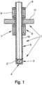
- the ultrasonic transducers shown in the figures are each an essential part of an ultrasonic flow measuring device, which is otherwise not shown, and initially have a transducer housing 1 and a transducer element 2, which is preferably a piezo element.
- the transducer element 2 is designed to transmit or receive ultrasonic waves.
- the transducer housing 1 has an ultrasound window 4 in a first area 3.
- the transducer element 2 is provided near the ultrasound window 4 of the transducer housing 1.
- the converter element 2 outside the converter housing 1.
- the ultrasonic transducers according to the invention are further improved in terms of preventing the transmission of housing waves.
- a second soft mechanical coupling system 9 is provided - in addition to the coupling system 7.
- This second coupling system 9 is essentially implemented in accordance with the first coupling system 7.
- the mechanical resonators 8 essentially work one behind the other in the direction of propagation of the housing waves, so the resonators work in series.
- the transducer element 2 is provided at the lower end of the transducer housing 1, that is to say at the end that faces the flowing medium or also protrudes into the flowing medium.
- the first mechanical coupling system 7 is realized at the upper end of the transducer housing 1, as it were part of the transducer housing 1.
- the known ultrasonic transducer and the ultrasonic transducer according to the invention can also be described insofar as it has been described so far in that it is designed in three parts, namely one lower first, the transducer element 2 receiving area 3, a mediating second area 5 and an upper third area 6, to which the first coupling system 7 belongs.
- the mediating second area 5 can specifically be a housing tube 10, the upper end of the converter housing 1 can be designed as a housing flange 11.
- the lower first area 3 of the converter housing 1, the mediating second area 5 of the converter housing 1, designed as a housing tube 10, the first coupling system 7 and the housing flange 11 are therefore arranged in series.
- the ultrasonic transducers are characterized in that of the two coupling systems 7, 9, the first coupling system 7 is on the side of the housing flange 11 close to the transducer element 2 and the second coupling system 9 is on the side of the housing flange 11 remote from the transducer element 2 is arranged.
- this is implemented in detail in such a way that the first coupling system 7 provided on the side of the housing flange 11 close to the converter element 2 is connected to the housing tube 2 at its end close to the converter element 2 and to the housing flange 11 at its end remote from the converter element 2 is connected, and that the second coupling system provided on the side of the housing flange 11 remote from the converter element 2 is connected to the housing tube 10 at its end remote from the converter element 2 and to the housing flange 11 at its end close to the converter element 2.
- the two coupling systems 7, 9 are therefore effective in an anti-parallel manner.
- connection of the coupling systems 7, 9 to the housing tube 10 and the housing flange 11 can be implemented in different ways.
- the end of the first coupling system 7 close to the converter element 2 and the end of the second coupling system 9 remote from the converter element 2 are welded to the housing tube 10.
- the end of the first coupling system 7 close to the converter element 2 and the end of the second coupling system 9 remote from the converter element 2 close to the converter element 2 are designed in one piece with the housing flange 11.
- the transducer element 2 is located at the end of the transducer housing 1 facing the medium whose flow rate is to be determined.
- the transducer elements in ultrasonic transducers are often piezo elements that cannot be used above a certain temperature, the Curie temperature. Consequently, there are also ultrasonic transducers in the prior art in which the transducer elements are provided at the end remote from the medium (cf German patent specification 198 12 458 and the same content European patent specification 1 046 886 ).
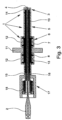
- the Fig. 2 and 3 show exemplary embodiments of ultrasonic transducers in which the transducer elements 2 are provided at the far end of the medium whose flow rate is to be measured.
- Fig. 2 and 3 in this respect preferred embodiments of ultrasonic transducers, as the coupling systems 7 and 9 are each provided with an externally circumferential groove 12, so an elastic hinge is realized, as it were, between a mechanical resonator 8 and the other mechanical resonator 8.
- the grooves 12 are designed in the shape of a circular arc in the base of the groove or are provided with transitions in the shape of a circular arc to the groove flanks, thereby avoiding mechanical overstress.
- the Fig. 3 shows a particularly preferred embodiment of an ultrasonic transducer.
- the transducer element 2 is provided at the end remote from the ultrasound window 4 of the transducer housing 1.
- An ultrasonic waveguide 15 is provided between the transducer element 2 and the ultrasound window 4 and is surrounded by a protective tube 16.
- the damping material 13 provided within the transducer housing 1 is only intended to dampen housing waves and, of course, not to negatively influence the transmission properties of the ultrasonic waveguide.
- Damping material 13 provided within the converter housing preferably bronze granules or bronze powder, works particularly well if or only if it is under a certain pressure inside the converter housing 1.
- pressure generating device 17 acting on the damping material 13 is provided, which in the exemplary embodiment is supported on one side on the converter housing 1 and on the other side has a spring 18 acting on the damping material 13, in the exemplary embodiment shown a plate spring package.
Landscapes
- Physics & Mathematics (AREA)
- Fluid Mechanics (AREA)
- General Physics & Mathematics (AREA)
- Engineering & Computer Science (AREA)
- Acoustics & Sound (AREA)
- Multimedia (AREA)
- Electromagnetism (AREA)
- Measuring Volume Flow (AREA)
Claims (10)
- Transducteur d'ultrasons en tant que partie d'un débitmètre à ultrasons, comportant un boîtier de transducteur (1) et un élément transducteur (2), dans lequel le boîtier de transducteur (1) présente une fenêtre à ultrasons (4) et un tube de boîtier (10), l'élément transducteur (2) est réalisé pour l'émission ou la réception d'ondes ultrasonores et est prévu soit près de la fenêtre à ultrasons (4) du boîtier de transducteur (2) soit loin de la fenêtre à ultrasons (4) du boîtier de transducteur (1), dans lequel un système d'accouplement mécanique (7) relativement mou est prévu, lequel présente au moins un résonateur mécanique (8) accouplé faiblement ou au moins deux résonateurs (8) accouplés faiblement, et dans lequel un deuxième système d'accouplement mécanique (9) mou est prévu,
caractérisé en ce quele deuxième système d'accouplement (9) est réalisé de manière à correspondre au premier système d'accouplement (7),en ce que le boîtier de transducteur (1) présente une bride de boîtier (11), en ce que, parmi les deux systèmes d'accouplement (7, 9), un système d'accouplement (7) est disposé sur le côté de la bride de boîtier (11) proche de la fenêtre à ultrasons (4) et l'autre système d'accouplement (9) est disposé sur le côté de la bride de boîtier (11) éloigné de la fenêtre à ultrasons (4), en ce que le système d'accouplement (7) prévu sur le côté de la bride de boîtier (11) proche de la fenêtre à ultrasons (4) est relié au tube de boîtier (10) à son extrémité proche de la fenêtre à ultrasons (4) et est relié à la bride de boîtier (11) à son extrémité éloignée de la fenêtre à ultrasons (4) et en ce que le système d'accouplement (9) prévu sur le côté de la bride de boîtier (10) éloigné de la fenêtre à ultrasons (4) est relié au tube de boîtier (10) à son extrémité éloignée de la fenêtre à ultrasons (4) et est relié à la bride de boîtier (11) à son extrémité proche de la fenêtre à ultrasons (4),de sorte que les deux systèmes d'accouplement (7, 9) soient actifs de manière anti-parallèle. - Transducteur d'ultrasons selon la revendication 1, caractérisé en ce que l'extrémité, proche de la fenêtre à ultrasons (4), du système d'accouplement (7) proche de la fenêtre à ultrasons (4) et l'extrémité, éloignée de la fenêtre ultrasons (4), du système d'accouplement (9) éloigné de la fenêtre ultrasons (4) sont soudées sur le tube de boîtier (10).
- Transducteur d'ultrasons selon la revendication 1 ou 2, caractérisé en ce que l'extrémité, éloignée de la fenêtre à ultrasons (4), du système d'accouplement (7) proche de la fenêtre à ultrasons (4) et l'extrémité, proche de la fenêtre ultrasons (4), du système d'accouplement (9) éloigné de la fenêtre ultrasons (4) sont réalisées d'une seule pièce avec la bride de boîtier (11).
- Transducteur d'ultrasons selon l'une des revendications 1 à 3, dans lequel le système d'accouplement mécanique (7) ou les systèmes d'accouplement (7, 9) présente(nt) au moins deux résonateurs mécaniques (8) accouplés faiblement, caractérisé en ce que le système d'accouplement (7) ou les systèmes d'accouplement (7, 9) est ou sont pourvu(s) d'une rainure périphérique extérieurement (12), par conséquent une charnière élastique est pour ainsi dire réalisée entre un résonateur mécanique (8) et l'autre résonateur mécanique (8).
- Transducteur d'ultrasons selon la revendication 4, caractérisé en ce que les rainures (12) sont réalisées en forme d'arc de cercle dans le fond de rainure ou ont des transitions en forme d'arc de cercle par rapport aux flancs de rainure.
- Transducteur d'ultrasons selon l'une des revendications 1 à 5, dans lequel le boîtier de transducteur (1) présente la fenêtre à ultrasons (4) dans une première région (3), dans lequel des ondes ultrasonores peuvent être transmises en tant qu'ondes de boîtier entre la première région (3) du boîtier de transducteur (1) par le biais d'une deuxième région de transmission (5) du boîtier de transducteur (1) dans une troisième région (6) du boîtier de transducteur opposée à la première région (3) du boîtier de transducteur (1), dans lequel un système d'accouplement mécanique (7) relativement mou est prévu dans la deuxième région (5) du boîtier de transducteur (1) et dans lequel le système d'accouplement (7) présente au moins deux résonateurs mécaniques (8) accouplés faiblement,
caractérisé en ce
qu'une matière d'amortissement (13) est prévue à l'intérieur du boîtier de transducteur (1), en particulier un granulat de bronze ou une poudre de bronze. - Transducteur d'ultrasons selon la revendication 6, caractérisé en ce que le boîtier de transducteur (1) présente, à son extrémité proche de la fenêtre ultrasons (4), une plaque de séparation (14) empêchant une pénétration de la matière d'amortissement (13) dans la fenêtre à ultrasons (4).
- Transducteur d'ultrasons selon la revendication 6 ou 7, dans lequel l'élément transducteur (2) est prévu à l'extrémité éloignée de la fenêtre ultrasons (4) du boîtier de transducteur (1) et un guide d'ondes ultrasonores (15) est prévu entre l'élément transducteur (2) et la fenêtre à ultrasons (4), caractérisé en ce qu'un tube de protection (16) entourant le guide d'ondes ultrasonores (15) est prévu.
- Transducteur d'ultrasons selon l'une des revendications 6 à 8, caractérisé en ce qu'un dispositif de génération de pression (17) agissant sur la matière d'amortissement (13) est prévu à l'extrémité du boîtier de transducteur (1) éloignée de la fenêtre à ultrasons (4).
- Transducteur d'ultrasons selon la revendication 9, caractérisé en ce que le dispositif de génération de pression (17) est supporté sur le boîtier de transducteur (1) d'un côté et présente, de l'autre côté, un ressort (18) agissant sur la matière d'amortissement (13), en particulier un ensemble de rondelles-ressorts.
Applications Claiming Priority (1)
| Application Number | Priority Date | Filing Date | Title |
|---|---|---|---|
| DE102013001351 | 2013-01-28 |
Publications (2)
| Publication Number | Publication Date |
|---|---|
| EP2762842A1 EP2762842A1 (fr) | 2014-08-06 |
| EP2762842B1 true EP2762842B1 (fr) | 2024-02-14 |
Family
ID=49955178
Family Applications (1)
| Application Number | Title | Priority Date | Filing Date |
|---|---|---|---|
| EP14000845.9A Active EP2762842B1 (fr) | 2013-01-28 | 2014-01-10 | Transducteur d'ultrasons pour un debitmetre a ultrasons |
Country Status (6)
| Country | Link |
|---|---|
| US (1) | US9489936B2 (fr) |
| EP (1) | EP2762842B1 (fr) |
| JP (1) | JP6000294B2 (fr) |
| CN (1) | CN103968903B (fr) |
| DE (1) | DE102014000110B4 (fr) |
| RU (1) | RU2566530C2 (fr) |
Families Citing this family (4)
| Publication number | Priority date | Publication date | Assignee | Title |
|---|---|---|---|---|
| DE102014115592A1 (de) | 2014-10-27 | 2016-04-28 | Endress + Hauser Flowtec Ag | Anordnung zum Aussenden und/oder Empfangen eines Ultraschall-Nutzsignals und Ultraschall-Durchflussmessgerät |
| DE102014115589A1 (de) * | 2014-10-27 | 2016-04-28 | Endress + Hauser Flowtec Ag | Anordnung zum Aussenden und/oder Empfangen eines Ultraschall-Nutzsignals und Ultraschall-Durchflussmessgerät |
| DE102016111133A1 (de) * | 2016-06-17 | 2017-12-21 | Endress+Hauser Flowtec Ag | Vorrichtung zur Bestimmung oder Überwachung des Volumen- und/oder Massendurchflusses eines fluiden Mediums in einer Rohrleitung |
| JP6141556B1 (ja) * | 2017-03-13 | 2017-06-07 | 東京計装株式会社 | 超音波流量計 |
Family Cites Families (29)
| Publication number | Priority date | Publication date | Assignee | Title |
|---|---|---|---|---|
| DE3027533C2 (de) * | 1980-07-21 | 1986-05-15 | Telsonic Aktiengesellschaft für elektronische Entwicklung und Fabrikation, Bronschhofen | Verfahren zur Erzeugung und Abstrahlung von Ultraschallenergie in Flüssigkeiten sowie Ultraschallresonator zur Ausführung des Verfahrens |
| GB2116046B (en) * | 1982-03-04 | 1985-05-22 | Wolf Gmbh Richard | Apparatus for disintegrating and removing calculi |
| US5159838A (en) * | 1989-07-27 | 1992-11-03 | Panametrics, Inc. | Marginally dispersive ultrasonic waveguides |
| US5275060A (en) | 1990-06-29 | 1994-01-04 | Panametrics, Inc. | Ultrasonic transducer system with crosstalk isolation |
| RU9955U1 (ru) * | 1998-01-06 | 1999-05-16 | Товарищество с ограниченной ответственностью Фирма "Метран" | Вихреакустический преобразователь расхода |
| DE19812458C2 (de) | 1998-03-23 | 2000-05-31 | Krohne Ag Basel | Sende- und/oder Empfangskopf eines Ultraschall-Durchflußmeßgerätes |
| US6059923A (en) * | 1998-09-18 | 2000-05-09 | 3M Innovative Properties Company | Rotary acoustic horn with sleeve |
| EP1046886B1 (fr) | 1999-04-21 | 2007-11-07 | Krohne AG | Transducteur d'émission ou de réception pour un débitmètre à ultrasons |
| US6513391B2 (en) * | 1999-05-17 | 2003-02-04 | Van Bekkum Jan Aart | Transmitting and/or receiving head for sonic flowmeters |
| AU5041500A (en) * | 1999-05-24 | 2000-12-12 | Joseph Baumoel | Transducer for sonic measurement of gas flow and related characteristics |
| JP2002112396A (ja) * | 2000-09-26 | 2002-04-12 | Krohne Messtech Gmbh & Co Kg | 超音波変換器 |
| US6626834B2 (en) * | 2001-01-25 | 2003-09-30 | Shane Dunne | Spiral scanner with electronic control |
| DE10205545B4 (de) | 2001-11-28 | 2005-09-15 | Krohne Ag | Durchflußmeßgerät |
| EP1316780B1 (fr) | 2001-11-28 | 2016-12-28 | Krohne AG | Débitmètre ultrasonique |
| US6841921B2 (en) * | 2002-11-04 | 2005-01-11 | Kimberly-Clark Worldwide, Inc. | Ultrasonic horn assembly stack component connector |
| US6652992B1 (en) * | 2002-12-20 | 2003-11-25 | Sulphco, Inc. | Corrosion resistant ultrasonic horn |
| US6876128B2 (en) * | 2003-07-09 | 2005-04-05 | General Electric Company | Short-circuit noise abatement device and method for a gas ultrasonic transducer |
| US7439654B2 (en) * | 2004-02-24 | 2008-10-21 | Air Products And Chemicals, Inc. | Transmission of ultrasonic energy into pressurized fluids |
| WO2006022592A1 (fr) * | 2004-08-26 | 2006-03-02 | Agency For Science, Technology And Research | Appareil pour usinage par ultrasons assiste par vibrations |
| DE102008033098C5 (de) * | 2008-07-15 | 2016-02-18 | Krohne Ag | Ultraschallwandler |
| EP2146190B1 (fr) * | 2008-07-15 | 2014-11-19 | Krohne AG | Convertisseur d'ultrasons |
| RU2386929C2 (ru) * | 2008-07-25 | 2010-04-20 | Общество с ограниченной ответственностью "Газпром добыча Астрахань" Открытого акционерного общества "Газпром" | Измерительная секция расходомера газожидкостного потока |
| GB201009062D0 (en) * | 2010-05-28 | 2010-07-14 | Cambridge Entpr Ltd | MEMS inertial sensor and method of inertial sensing |
| US8534138B2 (en) * | 2010-11-19 | 2013-09-17 | Cameron International Corporation | Chordal gas flowmeter with transducers installed outside the pressure boundary, housing and method |
| DE102010063538A1 (de) * | 2010-12-20 | 2012-06-21 | Endress + Hauser Flowtec Ag | Ultraschall-Durchflussmessgrät |
| DE102010064117A1 (de) * | 2010-12-23 | 2012-06-28 | Endress + Hauser Flowtec Ag | Ultraschallwandler |
| DE102011082615A1 (de) * | 2011-09-13 | 2013-03-14 | Endress + Hauser Flowtec Ag | Ultraschallwandler eines Ultraschall-Durchflussmessgeräts |
| EP2759809B1 (fr) * | 2013-01-28 | 2020-02-12 | Krohne AG | Transducteur à ultrasons |
| DE102014004747B4 (de) * | 2013-10-30 | 2023-02-16 | Krohne Ag | Ultraschall-Durchflussmesser |
-
2014
- 2014-01-10 EP EP14000845.9A patent/EP2762842B1/fr active Active
- 2014-01-11 DE DE102014000110.5A patent/DE102014000110B4/de active Active
- 2014-01-27 RU RU2014102468/28A patent/RU2566530C2/ru active
- 2014-01-28 US US14/165,999 patent/US9489936B2/en active Active
- 2014-01-28 CN CN201410041483.XA patent/CN103968903B/zh active Active
- 2014-01-28 JP JP2014013501A patent/JP6000294B2/ja active Active
Also Published As
| Publication number | Publication date |
|---|---|
| US9489936B2 (en) | 2016-11-08 |
| DE102014000110B4 (de) | 2024-07-18 |
| CN103968903A (zh) | 2014-08-06 |
| RU2566530C2 (ru) | 2015-10-27 |
| CN103968903B (zh) | 2018-01-23 |
| JP2014145769A (ja) | 2014-08-14 |
| US20140217854A1 (en) | 2014-08-07 |
| RU2014102468A (ru) | 2015-08-10 |
| DE102014000110A1 (de) | 2014-07-31 |
| EP2762842A1 (fr) | 2014-08-06 |
| JP6000294B2 (ja) | 2016-09-28 |
Similar Documents
| Publication | Publication Date | Title |
|---|---|---|
| DE102008033098C5 (de) | Ultraschallwandler | |
| EP2656017B1 (fr) | Élément de couplage d'un transducteur ultrasonique pour un débitmètre à ultrasons | |
| DE102014004747B4 (de) | Ultraschall-Durchflussmesser | |
| EP2762842B1 (fr) | Transducteur d'ultrasons pour un debitmetre a ultrasons | |
| EP2300786A1 (fr) | Capteur ultrasonique d'un système de mesure permettant la détermination et/ou la surveillance du débit d'un milieu de mesure à travers un tube de mesure | |
| DE102008029772A1 (de) | Verfahren und Messsystem zur Bestimmung und/oder Überwachung des Durchflusses eines Messmediums durch ein Messrohr | |
| DE102009032809A1 (de) | Ultraschallwandler | |
| EP2759810B1 (fr) | Assemblage d'un transducteur à ultrasons et un support de transducteur | |
| DE102010064117A1 (de) | Ultraschallwandler | |
| EP3855134A1 (fr) | Dispositif de mesure du débit d'écoulement d'un fluide | |
| DE102012015887B4 (de) | Vortex-Durchflussmessgerät | |
| EP3521774A1 (fr) | Dispositif de mesure d'écoulement à ultrasons et procédé de détermination de la vitesse d'écoulement | |
| EP2656018A1 (fr) | Débitmètre à ultrasons | |
| DE19812458C2 (de) | Sende- und/oder Empfangskopf eines Ultraschall-Durchflußmeßgerätes | |
| DE102009039633A1 (de) | Ultraschall-Durchflussmesser | |
| DE69413543T2 (de) | Verbesserungen bezüglich der überwachung von flüssigkeitsströmungen | |
| WO2003006932A1 (fr) | Tete de mesure pour debitmetre a ultrasons | |
| EP3663728B1 (fr) | Dispositif de mesure permettant de déterminer une grandeur de fluide et procédé de fabrication des dispositifs de mesure | |
| DE202015106040U1 (de) | System zur Durchflussmessung | |
| EP3910295B1 (fr) | Dispositif de mesure pour déterminer une variable de fluide | |
| DE102015107567A1 (de) | Anordnung umfassend einen Ultraschallwandler und Clamp-On Ultraschalldurchflussmessgerät | |
| EP1046886B1 (fr) | Transducteur d'émission ou de réception pour un débitmètre à ultrasons | |
| EP3748210B1 (fr) | Organe d'arrêt pour un fluide | |
| DE102011016963A1 (de) | Verfahren zur Messung von Durchflussmengen nach dem Prinzip der Ultraschalllaufzeitdifferenz | |
| DE102015210732A1 (de) | Vorrichtung zur Halterung von Schallwandlern sowie Ultraschalldurchflussmessgerät |
Legal Events
| Date | Code | Title | Description |
|---|---|---|---|
| PUAI | Public reference made under article 153(3) epc to a published international application that has entered the european phase |
Free format text: ORIGINAL CODE: 0009012 |
|
| 17P | Request for examination filed |
Effective date: 20140110 |
|
| AK | Designated contracting states |
Kind code of ref document: A1 Designated state(s): AL AT BE BG CH CY CZ DE DK EE ES FI FR GB GR HR HU IE IS IT LI LT LU LV MC MK MT NL NO PL PT RO RS SE SI SK SM TR |
|
| AX | Request for extension of the european patent |
Extension state: BA ME |
|
| R17P | Request for examination filed (corrected) |
Effective date: 20150206 |
|
| RBV | Designated contracting states (corrected) |
Designated state(s): AL AT BE BG CH CY CZ DE DK EE ES FI FR GB GR HR HU IE IS IT LI LT LU LV MC MK MT NL NO PL PT RO RS SE SI SK SM TR |
|
| STAA | Information on the status of an ep patent application or granted ep patent |
Free format text: STATUS: EXAMINATION IS IN PROGRESS |
|
| 17Q | First examination report despatched |
Effective date: 20190315 |
|
| GRAP | Despatch of communication of intention to grant a patent |
Free format text: ORIGINAL CODE: EPIDOSNIGR1 |
|
| STAA | Information on the status of an ep patent application or granted ep patent |
Free format text: STATUS: GRANT OF PATENT IS INTENDED |
|
| INTG | Intention to grant announced |
Effective date: 20231127 |
|
| GRAS | Grant fee paid |
Free format text: ORIGINAL CODE: EPIDOSNIGR3 |
|
| GRAA | (expected) grant |
Free format text: ORIGINAL CODE: 0009210 |
|
| STAA | Information on the status of an ep patent application or granted ep patent |
Free format text: STATUS: THE PATENT HAS BEEN GRANTED |
|
| AK | Designated contracting states |
Kind code of ref document: B1 Designated state(s): AL AT BE BG CH CY CZ DE DK EE ES FI FR GB GR HR HU IE IS IT LI LT LU LV MC MK MT NL NO PL PT RO RS SE SI SK SM TR |
|
| REG | Reference to a national code |
Ref country code: GB Ref legal event code: FG4D Free format text: NOT ENGLISH |
|
| REG | Reference to a national code |
Ref country code: CH Ref legal event code: EP |
|
| REG | Reference to a national code |
Ref country code: DE Ref legal event code: R096 Ref document number: 502014016765 Country of ref document: DE |
|
| P01 | Opt-out of the competence of the unified patent court (upc) registered |
Effective date: 20240129 |
|
| REG | Reference to a national code |
Ref country code: IE Ref legal event code: FG4D Free format text: LANGUAGE OF EP DOCUMENT: GERMAN |
|
| REG | Reference to a national code |
Ref country code: LT Ref legal event code: MG9D |
|
| REG | Reference to a national code |
Ref country code: NL Ref legal event code: FP |
|
| PG25 | Lapsed in a contracting state [announced via postgrant information from national office to epo] |
Ref country code: IS Free format text: LAPSE BECAUSE OF FAILURE TO SUBMIT A TRANSLATION OF THE DESCRIPTION OR TO PAY THE FEE WITHIN THE PRESCRIBED TIME-LIMIT Effective date: 20240614 |
|
| PG25 | Lapsed in a contracting state [announced via postgrant information from national office to epo] |
Ref country code: LT Free format text: LAPSE BECAUSE OF FAILURE TO SUBMIT A TRANSLATION OF THE DESCRIPTION OR TO PAY THE FEE WITHIN THE PRESCRIBED TIME-LIMIT Effective date: 20240214 |
|
| PG25 | Lapsed in a contracting state [announced via postgrant information from national office to epo] |
Ref country code: GR Free format text: LAPSE BECAUSE OF FAILURE TO SUBMIT A TRANSLATION OF THE DESCRIPTION OR TO PAY THE FEE WITHIN THE PRESCRIBED TIME-LIMIT Effective date: 20240515 |
|
| PG25 | Lapsed in a contracting state [announced via postgrant information from national office to epo] |
Ref country code: RS Free format text: LAPSE BECAUSE OF FAILURE TO SUBMIT A TRANSLATION OF THE DESCRIPTION OR TO PAY THE FEE WITHIN THE PRESCRIBED TIME-LIMIT Effective date: 20240514 Ref country code: HR Free format text: LAPSE BECAUSE OF FAILURE TO SUBMIT A TRANSLATION OF THE DESCRIPTION OR TO PAY THE FEE WITHIN THE PRESCRIBED TIME-LIMIT Effective date: 20240214 |
|
| PG25 | Lapsed in a contracting state [announced via postgrant information from national office to epo] |
Ref country code: ES Free format text: LAPSE BECAUSE OF FAILURE TO SUBMIT A TRANSLATION OF THE DESCRIPTION OR TO PAY THE FEE WITHIN THE PRESCRIBED TIME-LIMIT Effective date: 20240214 |
|
| PG25 | Lapsed in a contracting state [announced via postgrant information from national office to epo] |
Ref country code: RS Free format text: LAPSE BECAUSE OF FAILURE TO SUBMIT A TRANSLATION OF THE DESCRIPTION OR TO PAY THE FEE WITHIN THE PRESCRIBED TIME-LIMIT Effective date: 20240514 Ref country code: NO Free format text: LAPSE BECAUSE OF FAILURE TO SUBMIT A TRANSLATION OF THE DESCRIPTION OR TO PAY THE FEE WITHIN THE PRESCRIBED TIME-LIMIT Effective date: 20240514 Ref country code: LT Free format text: LAPSE BECAUSE OF FAILURE TO SUBMIT A TRANSLATION OF THE DESCRIPTION OR TO PAY THE FEE WITHIN THE PRESCRIBED TIME-LIMIT Effective date: 20240214 Ref country code: IS Free format text: LAPSE BECAUSE OF FAILURE TO SUBMIT A TRANSLATION OF THE DESCRIPTION OR TO PAY THE FEE WITHIN THE PRESCRIBED TIME-LIMIT Effective date: 20240614 Ref country code: HR Free format text: LAPSE BECAUSE OF FAILURE TO SUBMIT A TRANSLATION OF THE DESCRIPTION OR TO PAY THE FEE WITHIN THE PRESCRIBED TIME-LIMIT Effective date: 20240214 Ref country code: GR Free format text: LAPSE BECAUSE OF FAILURE TO SUBMIT A TRANSLATION OF THE DESCRIPTION OR TO PAY THE FEE WITHIN THE PRESCRIBED TIME-LIMIT Effective date: 20240515 Ref country code: FI Free format text: LAPSE BECAUSE OF FAILURE TO SUBMIT A TRANSLATION OF THE DESCRIPTION OR TO PAY THE FEE WITHIN THE PRESCRIBED TIME-LIMIT Effective date: 20240214 Ref country code: ES Free format text: LAPSE BECAUSE OF FAILURE TO SUBMIT A TRANSLATION OF THE DESCRIPTION OR TO PAY THE FEE WITHIN THE PRESCRIBED TIME-LIMIT Effective date: 20240214 Ref country code: BG Free format text: LAPSE BECAUSE OF FAILURE TO SUBMIT A TRANSLATION OF THE DESCRIPTION OR TO PAY THE FEE WITHIN THE PRESCRIBED TIME-LIMIT Effective date: 20240214 |
|
| PG25 | Lapsed in a contracting state [announced via postgrant information from national office to epo] |
Ref country code: PL Free format text: LAPSE BECAUSE OF FAILURE TO SUBMIT A TRANSLATION OF THE DESCRIPTION OR TO PAY THE FEE WITHIN THE PRESCRIBED TIME-LIMIT Effective date: 20240214 Ref country code: PT Free format text: LAPSE BECAUSE OF FAILURE TO SUBMIT A TRANSLATION OF THE DESCRIPTION OR TO PAY THE FEE WITHIN THE PRESCRIBED TIME-LIMIT Effective date: 20240614 |
|
| PG25 | Lapsed in a contracting state [announced via postgrant information from national office to epo] |
Ref country code: SE Free format text: LAPSE BECAUSE OF FAILURE TO SUBMIT A TRANSLATION OF THE DESCRIPTION OR TO PAY THE FEE WITHIN THE PRESCRIBED TIME-LIMIT Effective date: 20240214 Ref country code: PT Free format text: LAPSE BECAUSE OF FAILURE TO SUBMIT A TRANSLATION OF THE DESCRIPTION OR TO PAY THE FEE WITHIN THE PRESCRIBED TIME-LIMIT Effective date: 20240614 Ref country code: PL Free format text: LAPSE BECAUSE OF FAILURE TO SUBMIT A TRANSLATION OF THE DESCRIPTION OR TO PAY THE FEE WITHIN THE PRESCRIBED TIME-LIMIT Effective date: 20240214 Ref country code: LV Free format text: LAPSE BECAUSE OF FAILURE TO SUBMIT A TRANSLATION OF THE DESCRIPTION OR TO PAY THE FEE WITHIN THE PRESCRIBED TIME-LIMIT Effective date: 20240214 |
|
| PG25 | Lapsed in a contracting state [announced via postgrant information from national office to epo] |
Ref country code: DK Free format text: LAPSE BECAUSE OF FAILURE TO SUBMIT A TRANSLATION OF THE DESCRIPTION OR TO PAY THE FEE WITHIN THE PRESCRIBED TIME-LIMIT Effective date: 20240214 |
|
| PG25 | Lapsed in a contracting state [announced via postgrant information from national office to epo] |
Ref country code: SM Free format text: LAPSE BECAUSE OF FAILURE TO SUBMIT A TRANSLATION OF THE DESCRIPTION OR TO PAY THE FEE WITHIN THE PRESCRIBED TIME-LIMIT Effective date: 20240214 |
|
| P01 | Opt-out of the competence of the unified patent court (upc) registered |
Free format text: CASE NUMBER: APP_51651/2024 Effective date: 20240913 |
|
| PG25 | Lapsed in a contracting state [announced via postgrant information from national office to epo] |
Ref country code: EE Free format text: LAPSE BECAUSE OF FAILURE TO SUBMIT A TRANSLATION OF THE DESCRIPTION OR TO PAY THE FEE WITHIN THE PRESCRIBED TIME-LIMIT Effective date: 20240214 Ref country code: CZ Free format text: LAPSE BECAUSE OF FAILURE TO SUBMIT A TRANSLATION OF THE DESCRIPTION OR TO PAY THE FEE WITHIN THE PRESCRIBED TIME-LIMIT Effective date: 20240214 |
|
| PG25 | Lapsed in a contracting state [announced via postgrant information from national office to epo] |
Ref country code: SK Free format text: LAPSE BECAUSE OF FAILURE TO SUBMIT A TRANSLATION OF THE DESCRIPTION OR TO PAY THE FEE WITHIN THE PRESCRIBED TIME-LIMIT Effective date: 20240214 |
|
| P03 | Opt-out of the competence of the unified patent court (upc) deleted |
Free format text: CASE NUMBER: APP_51662/2024 |
|
| PG25 | Lapsed in a contracting state [announced via postgrant information from national office to epo] |
Ref country code: SM Free format text: LAPSE BECAUSE OF FAILURE TO SUBMIT A TRANSLATION OF THE DESCRIPTION OR TO PAY THE FEE WITHIN THE PRESCRIBED TIME-LIMIT Effective date: 20240214 Ref country code: SK Free format text: LAPSE BECAUSE OF FAILURE TO SUBMIT A TRANSLATION OF THE DESCRIPTION OR TO PAY THE FEE WITHIN THE PRESCRIBED TIME-LIMIT Effective date: 20240214 Ref country code: RO Free format text: LAPSE BECAUSE OF FAILURE TO SUBMIT A TRANSLATION OF THE DESCRIPTION OR TO PAY THE FEE WITHIN THE PRESCRIBED TIME-LIMIT Effective date: 20240214 Ref country code: EE Free format text: LAPSE BECAUSE OF FAILURE TO SUBMIT A TRANSLATION OF THE DESCRIPTION OR TO PAY THE FEE WITHIN THE PRESCRIBED TIME-LIMIT Effective date: 20240214 Ref country code: DK Free format text: LAPSE BECAUSE OF FAILURE TO SUBMIT A TRANSLATION OF THE DESCRIPTION OR TO PAY THE FEE WITHIN THE PRESCRIBED TIME-LIMIT Effective date: 20240214 Ref country code: CZ Free format text: LAPSE BECAUSE OF FAILURE TO SUBMIT A TRANSLATION OF THE DESCRIPTION OR TO PAY THE FEE WITHIN THE PRESCRIBED TIME-LIMIT Effective date: 20240214 |
|
| REG | Reference to a national code |
Ref country code: DE Ref legal event code: R097 Ref document number: 502014016765 Country of ref document: DE |
|
| PG25 | Lapsed in a contracting state [announced via postgrant information from national office to epo] |
Ref country code: IT Free format text: LAPSE BECAUSE OF FAILURE TO SUBMIT A TRANSLATION OF THE DESCRIPTION OR TO PAY THE FEE WITHIN THE PRESCRIBED TIME-LIMIT Effective date: 20240214 |
|
| PLBE | No opposition filed within time limit |
Free format text: ORIGINAL CODE: 0009261 |
|
| STAA | Information on the status of an ep patent application or granted ep patent |
Free format text: STATUS: NO OPPOSITION FILED WITHIN TIME LIMIT |
|
| PG25 | Lapsed in a contracting state [announced via postgrant information from national office to epo] |
Ref country code: IT Free format text: LAPSE BECAUSE OF FAILURE TO SUBMIT A TRANSLATION OF THE DESCRIPTION OR TO PAY THE FEE WITHIN THE PRESCRIBED TIME-LIMIT Effective date: 20240214 |
|
| 26N | No opposition filed |
Effective date: 20241115 |
|
| PG25 | Lapsed in a contracting state [announced via postgrant information from national office to epo] |
Ref country code: SI Free format text: LAPSE BECAUSE OF FAILURE TO SUBMIT A TRANSLATION OF THE DESCRIPTION OR TO PAY THE FEE WITHIN THE PRESCRIBED TIME-LIMIT Effective date: 20240214 |
|
| PG25 | Lapsed in a contracting state [announced via postgrant information from national office to epo] |
Ref country code: MC Free format text: LAPSE BECAUSE OF FAILURE TO SUBMIT A TRANSLATION OF THE DESCRIPTION OR TO PAY THE FEE WITHIN THE PRESCRIBED TIME-LIMIT Effective date: 20240214 Ref country code: LU Free format text: LAPSE BECAUSE OF NON-PAYMENT OF DUE FEES Effective date: 20250110 |
|
| PG25 | Lapsed in a contracting state [announced via postgrant information from national office to epo] |
Ref country code: BE Free format text: LAPSE BECAUSE OF NON-PAYMENT OF DUE FEES Effective date: 20250131 |
|
| REG | Reference to a national code |
Ref country code: BE Ref legal event code: MM Effective date: 20250131 |
|
| PG25 | Lapsed in a contracting state [announced via postgrant information from national office to epo] |
Ref country code: IE Free format text: LAPSE BECAUSE OF NON-PAYMENT OF DUE FEES Effective date: 20250110 |
|
| REG | Reference to a national code |
Ref country code: CH Ref legal event code: U11 Free format text: ST27 STATUS EVENT CODE: U-0-0-U10-U11 (AS PROVIDED BY THE NATIONAL OFFICE) Effective date: 20260201 |
|
| PGFP | Annual fee paid to national office [announced via postgrant information from national office to epo] |
Ref country code: NL Payment date: 20260121 Year of fee payment: 13 |
|
| REG | Reference to a national code |
Ref country code: AT Ref legal event code: MM01 Ref document number: 1657377 Country of ref document: AT Kind code of ref document: T Effective date: 20250110 |
|
| PGFP | Annual fee paid to national office [announced via postgrant information from national office to epo] |
Ref country code: GB Payment date: 20260123 Year of fee payment: 13 |
|
| PGFP | Annual fee paid to national office [announced via postgrant information from national office to epo] |
Ref country code: DE Payment date: 20260311 Year of fee payment: 13 |
|
| PG25 | Lapsed in a contracting state [announced via postgrant information from national office to epo] |
Ref country code: AT Free format text: LAPSE BECAUSE OF NON-PAYMENT OF DUE FEES Effective date: 20250110 |
|
| PGFP | Annual fee paid to national office [announced via postgrant information from national office to epo] |
Ref country code: FR Payment date: 20260123 Year of fee payment: 13 |
|
| PGFP | Annual fee paid to national office [announced via postgrant information from national office to epo] |
Ref country code: CH Payment date: 20260201 Year of fee payment: 13 |