EP2762877A1 - Kalibrierung eines chemischen Sensors in einer tragbaren elektronischen Vorrichtung - Google Patents
Kalibrierung eines chemischen Sensors in einer tragbaren elektronischen Vorrichtung Download PDFInfo
- Publication number
- EP2762877A1 EP2762877A1 EP13405013.7A EP13405013A EP2762877A1 EP 2762877 A1 EP2762877 A1 EP 2762877A1 EP 13405013 A EP13405013 A EP 13405013A EP 2762877 A1 EP2762877 A1 EP 2762877A1
- Authority
- EP
- European Patent Office
- Prior art keywords
- electronic device
- data
- sensor
- chemical
- network
- Prior art date
- Legal status (The legal status is an assumption and is not a legal conclusion. Google has not performed a legal analysis and makes no representation as to the accuracy of the status listed.)
- Withdrawn
Links
- 239000000126 substance Substances 0.000 title claims abstract description 138
- 238000000034 method Methods 0.000 claims abstract description 67
- 238000004891 communication Methods 0.000 claims description 38
- 239000012491 analyte Substances 0.000 claims description 19
- 230000035945 sensitivity Effects 0.000 claims description 16
- 238000005259 measurement Methods 0.000 claims description 15
- 230000001133 acceleration Effects 0.000 claims description 7
- 229910044991 metal oxide Inorganic materials 0.000 description 10
- 150000004706 metal oxides Chemical class 0.000 description 10
- 230000006870 function Effects 0.000 description 9
- LFQSCWFLJHTTHZ-UHFFFAOYSA-N Ethanol Chemical compound CCO LFQSCWFLJHTTHZ-UHFFFAOYSA-N 0.000 description 8
- 230000000875 corresponding effect Effects 0.000 description 7
- CSCPPACGZOOCGX-UHFFFAOYSA-N Acetone Chemical compound CC(C)=O CSCPPACGZOOCGX-UHFFFAOYSA-N 0.000 description 6
- 239000004065 semiconductor Substances 0.000 description 6
- 238000010586 diagram Methods 0.000 description 5
- 239000007789 gas Substances 0.000 description 5
- 231100000614 poison Toxicity 0.000 description 5
- 230000007096 poisonous effect Effects 0.000 description 5
- 238000012546 transfer Methods 0.000 description 5
- 239000000463 material Substances 0.000 description 4
- 239000012528 membrane Substances 0.000 description 4
- 238000001514 detection method Methods 0.000 description 3
- 238000011156 evaluation Methods 0.000 description 3
- 230000003287 optical effect Effects 0.000 description 3
- XLYOFNOQVPJJNP-UHFFFAOYSA-N water Substances O XLYOFNOQVPJJNP-UHFFFAOYSA-N 0.000 description 3
- XLOMVQKBTHCTTD-UHFFFAOYSA-N Zinc monoxide Chemical compound [Zn]=O XLOMVQKBTHCTTD-UHFFFAOYSA-N 0.000 description 2
- 230000008901 benefit Effects 0.000 description 2
- 238000006555 catalytic reaction Methods 0.000 description 2
- 238000004590 computer program Methods 0.000 description 2
- 239000004020 conductor Substances 0.000 description 2
- 238000005516 engineering process Methods 0.000 description 2
- 230000001747 exhibiting effect Effects 0.000 description 2
- 238000010438 heat treatment Methods 0.000 description 2
- 238000012986 modification Methods 0.000 description 2
- 230000004048 modification Effects 0.000 description 2
- 238000012544 monitoring process Methods 0.000 description 2
- 239000000758 substrate Substances 0.000 description 2
- 230000001960 triggered effect Effects 0.000 description 2
- 238000010521 absorption reaction Methods 0.000 description 1
- 239000000654 additive Substances 0.000 description 1
- 230000000996 additive effect Effects 0.000 description 1
- 238000003915 air pollution Methods 0.000 description 1
- 230000006399 behavior Effects 0.000 description 1
- 230000005540 biological transmission Effects 0.000 description 1
- 239000003054 catalyst Substances 0.000 description 1
- 230000008859 change Effects 0.000 description 1
- 238000006243 chemical reaction Methods 0.000 description 1
- 238000012790 confirmation Methods 0.000 description 1
- 230000002596 correlated effect Effects 0.000 description 1
- 230000001186 cumulative effect Effects 0.000 description 1
- 230000001419 dependent effect Effects 0.000 description 1
- 238000013461 design Methods 0.000 description 1
- 230000001627 detrimental effect Effects 0.000 description 1
- AJNVQOSZGJRYEI-UHFFFAOYSA-N digallium;oxygen(2-) Chemical compound [O-2].[O-2].[O-2].[Ga+3].[Ga+3] AJNVQOSZGJRYEI-UHFFFAOYSA-N 0.000 description 1
- 238000005538 encapsulation Methods 0.000 description 1
- 230000007613 environmental effect Effects 0.000 description 1
- 230000003203 everyday effect Effects 0.000 description 1
- 239000012530 fluid Substances 0.000 description 1
- 229910001195 gallium oxide Inorganic materials 0.000 description 1
- 229910003437 indium oxide Inorganic materials 0.000 description 1
- PJXISJQVUVHSOJ-UHFFFAOYSA-N indium(iii) oxide Chemical compound [O-2].[O-2].[O-2].[In+3].[In+3] PJXISJQVUVHSOJ-UHFFFAOYSA-N 0.000 description 1
- 238000012417 linear regression Methods 0.000 description 1
- 230000007774 longterm Effects 0.000 description 1
- 239000000203 mixture Substances 0.000 description 1
- QGLKJKCYBOYXKC-UHFFFAOYSA-N nonaoxidotritungsten Chemical compound O=[W]1(=O)O[W](=O)(=O)O[W](=O)(=O)O1 QGLKJKCYBOYXKC-UHFFFAOYSA-N 0.000 description 1
- 235000019645 odor Nutrition 0.000 description 1
- 230000002093 peripheral effect Effects 0.000 description 1
- 238000012545 processing Methods 0.000 description 1
- 230000004044 response Effects 0.000 description 1
- 238000000060 site-specific infrared dichroism spectroscopy Methods 0.000 description 1
- 238000001179 sorption measurement Methods 0.000 description 1
- 238000010897 surface acoustic wave method Methods 0.000 description 1
- XOLBLPGZBRYERU-UHFFFAOYSA-N tin dioxide Chemical compound O=[Sn]=O XOLBLPGZBRYERU-UHFFFAOYSA-N 0.000 description 1
- 229910001887 tin oxide Inorganic materials 0.000 description 1
- 238000012876 topography Methods 0.000 description 1
- 239000002341 toxic gas Substances 0.000 description 1
- 229910001930 tungsten oxide Inorganic materials 0.000 description 1
- 239000011787 zinc oxide Substances 0.000 description 1
Images
Classifications
-
- G—PHYSICS
- G01—MEASURING; TESTING
- G01N—INVESTIGATING OR ANALYSING MATERIALS BY DETERMINING THEIR CHEMICAL OR PHYSICAL PROPERTIES
- G01N33/00—Investigating or analysing materials by specific methods not covered by groups G01N1/00 - G01N31/00
- G01N33/0004—Gaseous mixtures, e.g. polluted air
- G01N33/0006—Calibrating gas analysers
-
- G—PHYSICS
- G01—MEASURING; TESTING
- G01D—MEASURING NOT SPECIALLY ADAPTED FOR A SPECIFIC VARIABLE; ARRANGEMENTS FOR MEASURING TWO OR MORE VARIABLES NOT COVERED IN A SINGLE OTHER SUBCLASS; TARIFF METERING APPARATUS; MEASURING OR TESTING NOT OTHERWISE PROVIDED FOR
- G01D18/00—Testing or calibrating apparatus or arrangements provided for in groups G01D1/00 - G01D15/00
-
- G—PHYSICS
- G01—MEASURING; TESTING
- G01N—INVESTIGATING OR ANALYSING MATERIALS BY DETERMINING THEIR CHEMICAL OR PHYSICAL PROPERTIES
- G01N33/00—Investigating or analysing materials by specific methods not covered by groups G01N1/00 - G01N31/00
- G01N33/0004—Gaseous mixtures, e.g. polluted air
- G01N33/0009—General constructional details of gas analysers, e.g. portable test equipment
- G01N33/007—Arrangements to check the analyser
Definitions
- the present invention relates to methods of determining calibration data for chemical sensors in electronic devices, to a corresponding system and to corresponding software.
- Portable electronic devices such as mobile phones, tablet computers, notebook computers etc. have become ubiquitous in everyday life.
- Such devices are nowadays equipped with a multitude of sensors, including gyroscopes, acceleration sensors, magnetic field sensors, proximity sensors, cameras, GPS modules etc.
- sensors that are sensitive to chemical analytes.
- Such sensors will in the following be called "chemical sensors”.
- semiconductor sensors are known for this purpose.
- Such sensors have a sensitive layer with at least one electrical property that changes in the presence of one or more analytes.
- the sensitive layer must be heated to a desired operational temperature.
- metal-oxide sensors are known; these sensors are to be operated at elevated temperatures of a few hundred degrees Celsius.
- a heater thermally coupled to the sensitive layer may be heated prior to and/or during taking a sensor reading.
- Drift may be understood as a variation in the sensor signal over time under identical environmental conditions in the absence of any chemical stimulus. Drift may impact the transfer function of the sensor in various forms, including an offset drift representing an additive component to the sensor signal and a sensitivity drift affecting a gradient of the transfer function. Any drift in turn may impact the accuracy of the sensor reading. The sensor should therefore be recalibrated from time to time to account for the drift.
- the present invention provides a method for operating a portable electronic device comprising a chemical sensor in which an impact of a drift of the chemical sensor on a reading of the chemical sensor may be reduced, the method having the features of claim 1. Further embodiments of the invention are laid down in the dependent claims.
- a method for calibrating a portable first electronic device comprising a first chemical sensor comprises:
- the calibration value that is obtained as a result of the method according of the invention may then be employed to modify a subsequent reading of the first chemical sensor.
- This modification may be done locally on the portable first electronic device, or the modification may for each sensor reading be carried out by a remote determination unit communicably connected to the portable first electronic device via a network.
- the readings of two sensors that can be assumed to be in the same chemical environment are compared, and the result of this comparison is taken into account for recalibrating the first chemical sensor.
- various criteria may be employed. The first and most important criterion is that the devices that contain the sensors are sufficiently close to one another. Additional criteria may be employed, as will be discussed further below.
- the two sensors sense the same chemical environment, they should yield the same readings if properly calibrated. If the readings differ significantly, this may be an indication that at least one of the sensors is miscalibrated and should be recalibrated. Recalibration is carried out by deriving at least one new calibration value for this sensor. Many possibilities exist for how to derive the new calibration value(s). For instance, if it is known that the second sensor is properly calibrated (e.g., if the second sensor is a reference sensor having a known precision), the calibration value(s) of the first sensor may be adjusted such that the reading of the first sensor will be substantially identical to the reading of the second sensor. Further examples will be discussed below.
- the first and second chemical sensors may be of the same or different types. Each of the sensors may be sensitive to one or more chemical analytes. There should be at least one common analyte to which both the first and the second sensor are sensitive. Even though water may in principle be considered to be a chemical analyte, in the context of the present invention, water, and in particular water vapor, is preferably not considered to be a chemical analyte. In other words, preferably a humidity sensor is not to be considered a chemical sensor.
- the first and/or second chemical sensor preferably is arranged inside a housing of the respective electronic device. An opening may be provided in the housing for exposing the chemical sensor to a fluid to be analyzed.
- the method is preferably computer-implemented and fully automated.
- at least the steps of comparing readings and deriving calibration values are preferably carried out automatically and without user intervention.
- the readings of the first and second sensor to be compared may be obtained in at least one of the following manners: According to a first possibility, readings that have been obtained in the course of other measurements in a certain time span before and/or after it was actually determined that the two devices are close to one another may be included in the comparison.
- the first and/or second electronic device may be actively triggered to carry out a measurement with its chemical sensor, in response to the determination that the first electronic device is located near the second electronic device. This may be done fully automatically, or it may be done by informing the user that a second device is nearby, and instructing the user to manually trigger a measurement by one or both of the devices.
- the measurement and/or the comparison may be made subject to further conditions, e.g., to the condition that other parameters confirm that the two devices are likely to sense the same chemical environment. This will be explained in more detail below.
- the first and second electronic devices may be considered to be "near" or "in proximity" to one another when a user of the devices indicates so.
- the determination whether the first electronic device is located near the second electronic device may comprise receiving user input to at least one of the first electronic device and the second electronic device, the user input indicating that the first electronic device is located near the second electronic device.
- the user input may, for instance, include one or more of the following: pressing a key or a key combination; typing a command; audio input by speaking a command into a microphone of one of the electronic devices; etc.
- the user input may contain an indication of the distance between the devices.
- an application program (app) or operating system service executed in the electronic device may request the user to confirm that the two devices are in the same room, or that they are at a distance of less than a certain number of meters of each other, or that they are placed side by side etc.
- proximity of the electronic devices is determined automatically.
- the first and second electronic devices may be considered to be “near” or “in proximity” to one another when they are within a certain predefined, fixed or variable spatial range as determined by an automatic determination method.
- the exact spatial extent of this range may vary and depends on the method by which proximity of the devices is detected. Various such methods may be employed.
- each of the first electronic device and the second electronic device may comprise a short-range communication module
- the determination whether the first electronic device is located near the second electronic device may comprise detecting whether the short-range communication module of the first electronic device and the short-range communication module of the second electronic device are within an operating range of each other.
- at least one of the first and second electronic devices monitors whether it is within the operating range of the short-range communication module of another electronic device. When this is the case, it can be concluded that the electronic devices must be located close to one another.
- the short-range communication module may be, for instance, a Bluetooth module, an infrared module, or a near-field communication (NFC) module such as an RFID module.
- NFC near-field communication
- the short-range communication module may also be a WLAN module, in particular, according to standard IEEE 802.11, configured for peer-to-peer communication.
- a short-range communication module typically has a limited operational range of less than approximately 100 m, the exact range depending on whether the module is operated indoors or outdoors and on the topography of the environment. In some embodiments (like with typical NFC modules) the range may be less than 1 m or even less than, say, 10 cm.
- a short-range communication module preferably enables direct communication between the devices (peer-to-peer communication), without employing a separate, dedicated network access point such as a WLAN router.
- Some short-range communication modules enable the determination of signal strength of other short-range communication modules within their operational range.
- at least one of the first and second electronic devices may be configured to measure the signal strength of the short-range communication module of the other electronic device and may employ the measured signal strength to estimate the distance between the devices and to determine whether the devices are located close to one another.
- each of the first electronic device and the second electronic device comprises a wireless network communication module, and the determination whether the first electronic device is located near the second electronic device comprises detecting whether the first electronic device and the second electronic device are located within the same cell of a wireless network.
- the wireless network may be a WLAN/Wi-FiTM network. If the WLAN network is operated in ad hoc mode, the first electronic device and the second electronic device may be considered to be located within the same cell of the network if they are able to communicate peer-to-peer, as described above. In this regard, the above definitions of proximity are partially redundant.
- the WLAN network is operated in infrastructure mode, i.e., if the WLAN network has a least one dedicated access point such as a router or a repeater, which serves as a bridge to another network infrastructure, in particular, a wired network infrastructure
- the first and second electronic device may be considered to be located within the same cell of the wireless network if they communicate via the same access point (e.g., via the same router or the same repeater).
- the wireless network may be a wireless telephony network, e.g., allowing data communication based on a UMTS or a GPRS standard.
- Two electronic devices may then be considered to be located within the same cell of the wireless network if they communicate through the same base station. While such cells can be rather large, it may be sufficient for recalibration purposes to know that both electronic devices are located within the same cell if the electronic devices are operated outdoors.
- the first electronic device comprises a network communication module for communication with a network
- the determination whether the first electronic device is located near the second electronic device comprises:
- the position of the second electronic device may be determined in a similar manner, or it may be known from other sources.
- the second electronic device may be a stationary device whose location is known and stored in a database.
- the second electronic device may be a reference station, and the second sensor may accordingly be a reference sensor having a known precision.
- the second electronic device may be a monitoring station operated by a government agency or a private contractor for monitoring air pollution. Such stations will often contain much more accurate chemical sensors than portable electronic devices such as smartphones or tablet computers.
- the various above-described methods for determining whether the first electronic device is located near the second electronic device may also be combined. For instance, if one of the above-described methods indicates that the two devices are near one another, this hypothesis may be confirmed by one or more of the other methods. In particular, if one of the automatic methods of determining proximity indicates that the first and second electronic device are close to one another, this may trigger a message to a user of the first and/or second electronic device that a nearby device was found, and one or both the devices may then request user confirmation that the devices are indeed close to each other.
- the above-described method rests on the assumption that the chemical environment of the first and second sensor is substantially the same.
- a key criterion that is employed in determining whether the environment is the same is proximity of the devices containing the sensors.
- this criterion may not always be sufficient. For instance, it is readily conceivable that the first device is kept in a user's pocket, whereas the second device is lying open on a table in the same room. In such situations, the chemical environments of the devices may be significantly different despite the fact that the devices are close to one another.
- the method may therefore employ additional criteria that are indicators of the environment of at least one of the devices.
- the method may comprise:
- a recalibration is carried out only if the context information indicates that the first and second sensor are in the same chemical environment.
- the context information may, for instance, include at least one of the following:
- humidity data may be obtained from humidity sensors of the first and second electronic device.
- Each humidity sensor is preferably disposed in a location that ensures that it senses the same environment as the associated chemical sensor.
- the humidity sensor is preferably disposed behind the same opening of the housing of the first electronic device, in particular, side by side with the chemical sensor.
- Many chemical sensors, in particular, semiconductor sensors are cross-sensitive to humidity, and humidity data are preferably used to correct a reading of the first chemical sensor.
- humidity data may also be used to determine whether the first electronic device and the second electronic device sense the same environment, since in this case the humidity readings obtained by both devices should be substantially the same. If the humidity readings are significantly different, this may be used as an indication that the chemical environments of the first and second device are different. As a consequence, the entire recalibration procedure may be stopped, or the user may be advised to ensure that the first and the second electronic device have the same environment.
- temperature data obtained from temperature sensors of the first and second electronic device may be used to determine whether the two devices are in a location with substantially the same temperature. If this is not the case, this may indicate that the environments of the first and second sensors are different, with the same consequences as above.
- acceleration data obtained from acceleration sensors of the first and second electronic device may indicate that the first and second electronic device are not handled in the same manner, e.g., that one electronic device is being carried around or wildly shaken while the other electronic device is placed at rest. If the data indicate that the handling conditions of the first and second electronic device are significantly different, the recalibration procedure may be stopped, or the user may be advised to ensure identical handling conditions of the two devices.
- acceleration and/or magnetometer data may be used to determine a spatial orientation of the first and second electronic device. Based on orientation information, the user may, e.g., be advised to put the two electronic devices in the same orientation to ensure identical measuring conditions, or otherwise the recalibration procedure may be stopped.
- Brightness may be used to determine whether the lighting conditions are substantially the same for the first and second electronic device, and/or acoustic data may be used to determine whether the acoustic environment is essentially the same. Significantly different lighting conditions or acoustic signals may indicate that the devices are not in the same environment, with the same consequences as above.
- Image data may be used to determine whether the first and second electronic device record images of the same environment.
- Incompatible images may indicate that the devices are not in the same environment or are handled differently, with the same consequences as above.
- the devices may comprise additional chemical sensors, which may be sensitive to the same or different analytes than the first and second chemical sensors, or the first and/or second sensors may have a plurality of cells. Signals of such additional sensors or of selected cells may be employed to obtain direct indications of the chemical environment of the first and second device.
- the context information may further include position information for the first and/or second electronic device and/or network information about a network to which the first electronic device is communicably attached. Such information allows a cross-check with other methods whether the first and second electronic devices are close to one another.
- the second sensor is a reference sensor whose reading is accurate to within a certain narrow range, or it may be known that one of the sensors has not been operated for an extended period of time or has been exposed to a poisonous or otherwise incompatible environment, which would make it highly likely that recalibration is necessary and that the reading of the sensor without recalibration would be inaccurate.
- "Poisonous" gases are gases that lead to short- or long-term sensor damage, which reduces sensor accuracy.
- sensors that are not frequently used are known to lose accuracy compared to regularly used sensors. In order to take such factors into account, each of the first chemical sensor and the second chemical sensor may be assigned an accuracy indicator.
- This indicator may relate to a known or estimated accuracy of the respective sensor. It may be a single value, e.g., a number between 0 and 1, or a more complex data structure, e.g., an accuracy vector, the vector elements relating to different parameters that are relevant to accuracy such as design accuracy, sensor age, and/or sensor history (e.g., frequency of usage, last usage, usage conditions during the last measurements, last reconditioning, last recalibration etc.).
- the at least one calibration value for the first chemical sensor may then be determined subject to the accuracy indicators associated with the first and second electronic sensor. For instance, if the accuracy indicators indicate that the first sensor is likely to have a higher accuracy than the second sensor, no recalibration of the first sensor might be carried out at all. If the accuracy indicators indicate that both the first sensor and the second sensor have a similar expected accuracy, recalibration of both sensors may be carried out such that the sensor readings after recalibration will be the average of the readings before recalibration, etc.
- the calibration values (which may also be called compensation values) that are derived by the present method may include any parameter related to the transfer function of the sensor.
- the transfer function relates the concentration of an analyte to which the first chemical sensor is sensitive to a sensor reading.
- the calibration values may include any of the following:
- the portable first electronic device may be one of the following, without limitation: a mobile phone, a handheld computer, an electronic reader, a tablet computer, a game controller, a pointing device, a photo or a video camera, and a computer peripheral.
- the second electronic device may also be a portable electronic device, including any of the device types mentioned above, or may be a stationary electronic device.
- the present invention provides a method of determining calibration data for electronic devices, each electronic device being equipped with at least one chemical sensor, which method may be carried out by a server that is located remotely from the electronic devices and communicably connected to the electronic devices via a network.
- the method comprises:
- the method may further comprise sending the derived calibration data to at least one of the electronic devices or to a remote determination unit communicably connected to at least one of the electronic devices via a network.
- the same considerations apply to this method as for the method for operating a portable electronic device that is discussed above.
- the same methods may be employed for determining whether two or more electronic devices are located near one another as discussed above.
- the method may optionally comprise triggering at least one of the electronic devices that are near one another to carry out a measurement with their chemical sensors, so as to obtain a reading.
- context information may be obtained about at least one of the electronic devices, and the further calibrations steps may be carried out subject to the context information.
- at least one of the electronic devices may be a reference station equipped with a reference sensor.
- the present invention provides a system for determining calibration data for electronic devices equipped with at least one chemical sensor, the system comprising:
- the system may comprise a database for storing the locations of the electronic device.
- the system may further comprise a sending module for sending the derived calibration data to at least one of the electronic devices or to a remote determination unit communicably connected to at least one of the electronic devices via a network.
- the modules of the system may be implemented partially or fully in software that is executed on a general-purpose processor of the system.
- the system may be embodied by a server or a server cluster.
- the present invention provides a computer program code element that carries out central parts of the methods described above when executed in a processor of a system for determining calibration data.
- the computer program element comprises computer-implemented instructions to cause a processor to carry out a particular method. It can be provided in any suitable form, including source code or object code. In particular, it can be stored on a computer-readable medium or embodied in a data stream. The data stream may be accessible through a network such as the Internet.
- the present invention further relates to a program element comprising computer code that, when executed in a processor, carries out the following method:
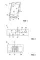
- FIG. 1 illustrates a portable electronic device in the form of a mobile phone 1.
- the mobile phone has a housing 10, an input/output device in the form of a touchscreen display 17 and a further input device in the form of a pushbutton 12.
- sensors such as a humidity sensor, a temperature sensor and a sensor for detecting at least one chemical analyte (i.e., one or more chemical sensors) may be arranged.
- the chemical sensor may comprise one or more sensor cells, each sensor cell exhibiting a different sensitivity to selected analytes.
- the mobile phone runs an application program (app) or operating system service for operating the chemical sensor.
- FIG. 2 shows a schematic hardware-oriented block diagram of the mobile phone 1.
- a microprocessor 21 is connected via leads 22 to a chemical sensor 11 and at least one further sensor 23 (e.g., a humidity sensor, a temperature sensor, an inertial sensor etc.).
- the chemical sensor 11 contains signal processing capability in order to output a raw or preprocessed measured variable.
- a routine for analyzing the measured variable supplied by the chemical sensor 11 and outputting a result of the measurement may be executed by an evaluation unit.
- a hardware of the evaluation unit may be represented by the microprocessor 21, and a software of the evaluation unit may be represented by a program element stored in a memory 25 connected to the microprocessor 21 via a bus system 24.
- a short-range communication module 26, e.g. a Bluetooth module, and another wireless interface 27, e.g. a UMTS module or a WLAN module, may be connected to the microprocessor 21.
- Input/output devices as previously mentioned may further be connected to the microprocessor 21.
- the present invention employs one or more chemical sensors that are sensitive to at least one chemical analyte.
- Each of these sensors may comprise one or more semiconductor sensor elements.
- These semiconductor sensor elements may comprise at least one sensitive layer, for which at least one electrical property (in particular, conductivity) changes in the presence of at least one chemical analyte due to adsorption and/or chemical reactions on the surface of the sensitive layer (including catalytic reactions in which the sensitive layer acts as a catalyst).
- the sensor may include at least one heat source integrated within the sensor to heat the sensitive layer to an operating temperature thereof.
- the sensitive layer may be a metal oxide (MOX) layer. Sensors having at least one MOX layer as a sensitive layer will in the following be called MOX sensors.
- the metal oxide may be, e.g., tin oxide, tungsten oxide, gallium oxide, indium oxide, or zinc oxide.
- Each sensor may comprise two or more sensor elements ("cells") that have different sensitivities to selected analytes.
- the sensor cells may be arranged in a one- or two-dimensional array.
- Each sensor cell may provide a sensitive layer of a material exhibiting different sensitivity to some or all of the analytes that the sensor is sensitive to.
- each cell of the sensor array may specifically be mainly sensitive to a different analyte and as such may enable the portable electronic device to detect the presence or absence or concentration of such analyte.
- "Mainly” in this context shall mean that a sensor cell is more sensitive to the subject analyte than to other analytes.
- a sensor cell of such sensor array may exhibit not only sensitivity to its main analyte, but also to analytes other than the main analyte since such sensor cell may exhibit a cross-sensitivity to one or more analytes possibly representing main analytes for other cells.
- one cell is sensitive to ethanol with a certain sensitivity and to acetone with a certain other sensitivity
- another sensor cell is sensitive with a different ratio of sensitivities to ethanol and acetone, such that by comparing the signals of the two cells, the analytes ethanol and acetone can be separated.
- the sensor cells may have different sensitivities to multiple different analytes at different operating conditions.
- the sensor cell may mainly be receptive to a first analyte x when being heated to a first temperature Tx, and may mainly be receptive to a second analyte y when being heated to a second temperature Ty which is different from the first temperature Tx.
- each of the sensor cells or specific groups of sensor cells may be provided with an individual heater. In other embodiments, all cells may be heated by the same heater.
- the first and/or second sensor may comprise only a single sensor cell that has different sensitivities to multiple different analytes at different operating conditions.
- the individual sensor cells may be embodied as discrete sensor cells.
- the sensor cells are preferably mounted on a common conductor board of the portable electronic device.
- the sensor cells may take the form of multiple chips. Each individual chip may be packaged, i.e. encapsulated, separately. In an alternative arrangement, multiple or all chips may be packaged in a common package, such that these chips are encapsulated by a common encapsulation.
- multiple or all sensor cells are monolithically integrated in a common sensor chip with a common substrate for multiple or all sensor cells. Such a monolithic multiple sensor chip may still be encapsulated and be arranged on and electrically connected to a conductor board of the portable electronic device.
- FIGs 3 and 4 illustrate, in a highly schematic manner, an example of the sensor chip 30 implementing a chemical sensor as discussed above.
- the chip 30 comprises a chemical sensor structure 31 which takes the form of a sensor array comprising multiple sensor cells 32, in the present example, six times six sensor cells 32.
- a humidity sensitive structure 33 is arranged next to the chemical sensor structure 32, and electronic circuitry 34 is integrated into the chemical sensor chip 30, which electronic circuitry 34 is responsible for linearizing and A/D converting the sensor signal and for outputting a measured variable.
- Figure 4 illustrates a cut through a schematic individual sensor cell 32. A recess is manufactured into a substrate 38 of the sensor chip to obtain a thin membrane 37.
- a sensitive layer 35 is arranged on top of the thin membrane, and a resistive heater 36 is arranged in or on top of the membrane.
- the membrane may be denoted as a micro-hotplate.
- the sensitive layer 35 is made of a metal oxide material. It is heated by the heater 36 prior to and during taking a sensor reading, so as to ensure that the temperature of the sensitive layer 35 is sufficient for having a catalytic reaction between the analyte/s and the sensitive layer 35 take place at a sufficient rate. As a result, an electrical conductivity of the sensitive layer 35 is modified.
- the operating temperature may vary subject to the material used from about 100 °C to about 450 °C.
- a sensor may be used that functions on an optical principle, i.e., an optical property of a sensor material may be modified such as its transmission rate, and this optical property is determined.
- an optical principle i.e., an optical property of a sensor material may be modified such as its transmission rate, and this optical property is determined.
- Another possible measurement principle is a chemomechanical principle, in which a mass change upon absorption is transformed into a surface acoustic wave or into a cantilever resonance, for example.
- Applications may include the detection of toxic gases, the detection of ethanol in a user's breath, the detection and/or identification of odors, and many more.
- the mobile phone equipped with the chemical sensor may in addition to its original function provide chemical information as to its environment.
- the user may learn about chemical substances and compositions present in the device's surroundings, and may use, transmit or else further analyze such information. Such information may be transmitted elsewhere and be used elsewhere, or the user himself/herself may benefit from the information provided by the chemical sensor.
- the electronic device may be primarily designed for computing and/or telecommunication and/or other tasks in the IT arena, but may be enhanced by the function of providing chemical information as to its environment.
- calibration values may be provided. For determining such calibration values, reference readings may be taken by the chemical sensor from time to time, preferably in the absence of one or more analytes to which the chemical sensor is sensitive. In the alternative or in addition to this, calibration values may be determined based on operational data of the electronic device, e.g., heating data in case the chemical sensor includes a heater, and specifically the cumulative time the heater was activated or deactivated in a given period in time. For example, the less the heater was activated over a certain period in time, the more likely a drift has occurred such that the compensation value preferably is dimensioned to compensate for a larger drift.
- operational data of the electronic device e.g., heating data in case the chemical sensor includes a heater, and specifically the cumulative time the heater was activated or deactivated in a given period in time. For example, the less the heater was activated over a certain period in time, the more likely a drift has occurred such that the compensation value preferably is dimensioned to compensate for a larger drift.
- calibration values may also be determined based on sensor readings from a sensor of the electronic device either different from the chemical sensor, or from a different sensor cell of the same chemical sensor comprising multiple sensor cells.
- sensor may be, e.g., a humidity sensor or a temperature sensor.
- the calibration value may then depend on the previous and/or present sensor measurements by a suitable function. For example, exposure to poisonous gases or infrequent sensor use might lead to sensor drift or loss of accuracy, which in turn requires a compensation value dimensioned to compensate for such influences on sensor performance.
- a prediction model may be provided for predicting calibration values on the basis of past calibration values and possibly taking into account the sensor history. For instance, linear regression may be applied to past offset compensation values to extrapolate future offset compensation values.
- this kind of procedure for determining and predicting calibration values may still lead to wrong results.
- the prediction model may fail if the sensor has not been operated for an extended period of time, or if the sensor has been exposed to a detrimental chemical environment, for instance to poisonous gases, for some time.
- the above-described procedure may be well adapted to compensating offset drifts, sensitivity drifts cannot readily be detected and compensated by this procedure. Accordingly, it may be required to recalibrate the sensor from time to time by different methods. Recalibration may also be desired after the sensor has been reconditioned, e.g. by extended heating of the sensitive layer in case of a semiconductor sensor.
- the present invention provides methods for recalibration. Exemplary embodiments of such methods and a corresponding system are illustrated in Figures 5 to 7 .
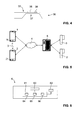
- Figure 5 illustrates a first mobile phone 1 equipped with a first chemical sensor 11 (shown only very schematically) and a second mobile phone 2 equipped with a second chemical sensor 21.
- Both mobile phones are equipped with a short-range communication module such as a Bluetooth module and with a network communication module such as a LAN module, as discussed in conjunction with Figure 2 .
- the first mobile phone 1 executes an application program (app) or operating system service (henceforth called service) for operating its chemical sensor 11.
- the app or service monitors whether a second electronic device, e.g. the second mobile phone 2, is within the reach of the short-range communication module of the first mobile phone 1.
- the app or service When the app or service determines in this manner that a second electronic device is nearby, it requests context information from the second electronic device, for instance humidity data, temperature data, pressure data; acceleration data, magnetometer data, brightness data, image data, acoustic data and GPS data from the second electronic device.
- These data may be transmitted through the short-range communication interface 3 established by the short-range communication modules of the involved electronic devices, or the data may be transmitted through a network 4 to which both the first mobile phone 1 and the second electronic device are communicably attached, employing the network communication modules of the electronic devices.
- the short-range communication interface 3 is only used for detecting proximity of the second electronic device, whereas the subsequent data communication is carried out through a network, which usually will have a higher bandwidth.
- the app or service then compares the context information received from the second electronic device with corresponding information derived from its own sensors. It is also conceivable that this comparison is not carried out by the app or service, but by a remote server 6 communicably connected to the network 4. If this comparison indicates that both the first mobile phone 1 and the second electronic device are likely to have the same chemical environment, the app or service starts a recalibration procedure as detailed below.
- the app or service periodically sends position information, network information and further context information such as accelerometer data, humidity data and temperature data via the network 4 to the remote server 6.
- the remote server 6 receives similar data from a plurality of further electronic devices. It determines the geolocation of each electronic device from the data and compares the geolocations of the electronic devices to determine whether any two or more electronic devices are near one another.
- the remote server 6 is in communication with a plurality of reference stations 5, 5' equipped with reference sensors. The geolocations of these reference stations are known to the server 6.
- the server 6 compares the geolocations of the electronic devices to the known geolocations of the reference stations to determine whether any electronic device is near one of the reference stations. If, for any specific electronic device, the server has determined that another electronic device or a reference station is nearby, it sends a corresponding message to the corresponding electronic device so as to start a recalibration procedure.
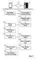
- step 711 the mobile phone 1 sends position, network and context data to the remote server 3 via the network 4.
- step 712 the remote server 3 receives the position, network and context data.
- step 713 the server 3 determines whether, for any given portable electronic device, another electronic device with another chemical sensor is nearby and is likely to have the same chemical environment. If this is the case, it starts the recalibration procedure.
- a possible embodiment of a recalibration procedure comprises the subsequent steps 714 to 721.
- the server requests readings from those electronic devices that have been determined to have the same chemical environment.
- Each electronic device receives the request in step 715 and obtains at least one reading in step 716.
- the reading may include the result of a recent measurement, and/or a new measurement may be triggered by the request.
- the reading may include results from one or more different cells of the chemical sensor.
- the reading is transmitted to the server in step 717 and is received by the server in step 718.
- Each reading may include an accuracy indicator, which may include parameters relating to the sensor identity and history.
- step 719 calibration values are derived from the reference readings.
- the accuracy indicators are compared. If this comparison shows that the expected accuracy of one of the sensors is higher than of the other sensors, the reading of that sensor may be assumed to be correct, and the calibration values of the other sensors may be set to such values that the readings of the other sensors correspond to the reading of the sensor having the highest expected accuracy.
- a further plausibility check may be carried out at this stage by comparing the readings from sensor cells that are not subject to recalibration. If one or more of these readings indicate that the sensors have significantly different chemical environments, the procedure may still be stopped.
- step 720 the new calibration values are sent back to at least one of the electronic devices. They are received by electronic device in step 721 and are subsequently applied to future measurements in step 722. Instead, it is also possible to store the new calibration values in a remote database. In this case, whenever a measurement with a chemical sensor is carried out, the corresponding electronic devices would send their uncalibrated sensor readings to a remote determination unit, and the remote determination unit would apply the calibration values from the database to derive calibrated readings.
- User intervention may be foreseen in various stages of the procedure. For instance, if it has been determined that the two electronic devices are near each other, the user may be requested to confirm that the electronic devices have the same chemical environment and are not exposed to any stimuli that might interfere with the calibration procedure. It is also conceivable that the user is requested to manually trigger a measurement by the chemical sensor of one or both of the involved electronic devices.
- the server has a processor 61, a memory 62 and a network communication module 63.
- the processor 61 executes a server program that has several software modules, including the following: a locating module 64 configured to receive data through the network communication module 63, to extract position, network and context data relating to at least one electronic device from the received data, and to determine a location of each device for which data is received, based on the received data; a matching module 65 configured to determine whether any two or more electronic devices are near one another; and a calibration module 66 configured to receive reference readings of the chemical sensors of the electronic devices that are near each other, and, subject to the reference readings, deriving calibration data for at least one of the electronic devices that are near each other.
Landscapes
- Chemical & Material Sciences (AREA)
- Engineering & Computer Science (AREA)
- Health & Medical Sciences (AREA)
- Life Sciences & Earth Sciences (AREA)
- Physics & Mathematics (AREA)
- General Physics & Mathematics (AREA)
- Analytical Chemistry (AREA)
- Medicinal Chemistry (AREA)
- Food Science & Technology (AREA)
- Biochemistry (AREA)
- General Health & Medical Sciences (AREA)
- Combustion & Propulsion (AREA)
- Immunology (AREA)
- Pathology (AREA)
- Telephone Function (AREA)
- Investigating Or Analyzing Materials By The Use Of Electric Means (AREA)
Priority Applications (2)
| Application Number | Priority Date | Filing Date | Title |
|---|---|---|---|
| EP13405013.7A EP2762877A1 (de) | 2013-01-31 | 2013-01-31 | Kalibrierung eines chemischen Sensors in einer tragbaren elektronischen Vorrichtung |
| US14/168,136 US20140244198A1 (en) | 2013-01-31 | 2014-01-30 | Calibration of a chemical sensor in a portable electronic device |
Applications Claiming Priority (1)
| Application Number | Priority Date | Filing Date | Title |
|---|---|---|---|
| EP13405013.7A EP2762877A1 (de) | 2013-01-31 | 2013-01-31 | Kalibrierung eines chemischen Sensors in einer tragbaren elektronischen Vorrichtung |
Publications (1)
| Publication Number | Publication Date |
|---|---|
| EP2762877A1 true EP2762877A1 (de) | 2014-08-06 |
Family
ID=47754406
Family Applications (1)
| Application Number | Title | Priority Date | Filing Date |
|---|---|---|---|
| EP13405013.7A Withdrawn EP2762877A1 (de) | 2013-01-31 | 2013-01-31 | Kalibrierung eines chemischen Sensors in einer tragbaren elektronischen Vorrichtung |
Country Status (2)
| Country | Link |
|---|---|
| US (1) | US20140244198A1 (de) |
| EP (1) | EP2762877A1 (de) |
Cited By (6)
| Publication number | Priority date | Publication date | Assignee | Title |
|---|---|---|---|---|
| WO2016030386A1 (en) * | 2014-08-28 | 2016-03-03 | Koninklijke Philips N.V. | Sensor system and sensing method |
| WO2016133439A1 (en) * | 2015-02-19 | 2016-08-25 | Telefonaktiebolaget Lm Ericsson (Publ) | Method device and computer program for calibration of a sensor |
| WO2017067281A1 (zh) * | 2015-10-19 | 2017-04-27 | 广东欧珀移动通信有限公司 | 一种指纹传感器的校准方法、装置及终端 |
| WO2018125425A1 (en) | 2016-12-27 | 2018-07-05 | Intel Corporation | Normalization of sensors |
| CN108291898A (zh) * | 2015-11-11 | 2018-07-17 | 三星电子株式会社 | 用于利用气体传感器的电子设备和方法 |
| WO2020206438A1 (en) | 2019-04-05 | 2020-10-08 | H2Scan Corporation | Methods and systems for determining a target gas concentration in a fluid environment |
Families Citing this family (25)
| Publication number | Priority date | Publication date | Assignee | Title |
|---|---|---|---|---|
| KR20140118667A (ko) | 2013-03-29 | 2014-10-08 | 삼성전자주식회사 | 디스플레이장치 및 그 제어방법 |
| WO2014198564A1 (en) * | 2013-06-11 | 2014-12-18 | Koninklijke Philips N.V. | A method of calibrating a sensor |
| US9537542B2 (en) * | 2014-05-04 | 2017-01-03 | Beijing Lenovo Software Ltd. | Method for processing information and electronic device |
| US10522109B2 (en) * | 2016-06-14 | 2019-12-31 | Lenovo (Singapore) Pte. Ltd. | Adjusting brightness settings based on context data |
| US10436616B2 (en) * | 2016-08-08 | 2019-10-08 | Hamilton Sundstrand Corporation | Passive monitoring of sensor calibration status |
| US10578641B2 (en) * | 2016-08-22 | 2020-03-03 | Nxp Usa, Inc. | Methods and systems for electrically calibrating transducers |
| WO2018170444A1 (en) | 2017-03-17 | 2018-09-20 | The Regents Of The University Of Michigan | Method and apparatus for constructing informative outcomes to guide multi-policy decision making |
| US10564641B2 (en) | 2018-07-20 | 2020-02-18 | May Mobility, Inc. | Multi-perspective system and method for behavioral policy selection by an autonomous agent |
| US10614709B2 (en) | 2018-07-24 | 2020-04-07 | May Mobility, Inc. | Systems and methods for implementing multimodal safety operations with an autonomous agent |
| EP3859544B1 (de) * | 2018-09-28 | 2024-05-01 | Mitsubishi Electric Corporation | Servervorrichtung, datenverteilungssystem, datenbereitstellungsverfahren und programm |
| US10969470B2 (en) | 2019-02-15 | 2021-04-06 | May Mobility, Inc. | Systems and methods for intelligently calibrating infrastructure devices using onboard sensors of an autonomous agent |
| CN112198208B (zh) * | 2019-06-23 | 2022-01-14 | 宁波方太厨具有限公司 | 一种甲醛检测方法及甲醛检测装置 |
| CN112198207B (zh) * | 2019-06-23 | 2022-01-11 | 宁波方太厨具有限公司 | 一种甲醛检测方法及甲醛检测装置 |
| CN112198209B (zh) * | 2019-06-23 | 2022-01-11 | 宁波方太厨具有限公司 | 一种甲醛检测方法及甲醛检测装置 |
| WO2022006418A1 (en) | 2020-07-01 | 2022-01-06 | May Mobility, Inc. | Method and system for dynamically curating autonomous vehicle policies |
| DE102020210605A1 (de) | 2020-08-20 | 2022-02-24 | Robert Bosch Gesellschaft mit beschränkter Haftung | Verfahren zur Korrektur eines Offsets und/oder einer Empfindlichkeit eines zweiten Sensors mithilfe eines ersten Sensors, Sensorsystem |
| EP4260009A4 (de) | 2020-12-14 | 2024-11-20 | May Mobility, Inc. | Autonomes fahrzeugsicherheitsplattformsystem und verfahren |
| EP4264181A4 (de) | 2020-12-17 | 2024-10-30 | May Mobility, Inc. | Verfahren und system zur dynamischen aktualisierung einer umgebungsdarstellung eines autonomen agenten |
| EP4314708A4 (de) | 2021-04-02 | 2024-12-25 | May Mobility, Inc. | Verfahren und system zum betrieb eines autonomen agenten mit unvollständigen umgebungsinformationen |
| WO2022256249A1 (en) | 2021-06-02 | 2022-12-08 | May Mobility, Inc. | Method and system for remote assistance of an autonomous agent |
| WO2023102098A1 (en) | 2021-12-01 | 2023-06-08 | May Mobility, Inc. | Method and system for impact-based operation of an autonomous agent |
| US12296849B2 (en) | 2021-12-02 | 2025-05-13 | May Mobility, Inc. | Method and system for feasibility-based operation of an autonomous agent |
| JP7851524B2 (ja) | 2022-02-14 | 2026-04-27 | メイ モビリティー,インコーポレイテッド | 自律エージェントの条件付き動作のための方法及びシステム |
| WO2024117948A1 (en) * | 2022-11-30 | 2024-06-06 | Epiroc Rock Drills Aktiebolag | Method, system, and control unit for handling measurements in an underground environment |
| JP2026500243A (ja) | 2022-12-13 | 2026-01-06 | メイ モビリティー,インコーポレイテッド | 自律車両が遭遇し得るリスクを評価し軽減するための方法およびシステム |
Citations (4)
| Publication number | Priority date | Publication date | Assignee | Title |
|---|---|---|---|---|
| US4569223A (en) * | 1983-07-28 | 1986-02-11 | Huebner Hans J | Method of and apparatus for multiple detector measurement of an environmental parameter |
| US6266995B1 (en) * | 1999-05-20 | 2001-07-31 | Respiratory Management Services, Inc. | Portable medical gas system tester |
| US20100326165A1 (en) * | 2009-06-25 | 2010-12-30 | Honeywell International Inc. | Detector test device |
| US20120330596A1 (en) * | 2011-06-21 | 2012-12-27 | General Electric Company | Self-calibrating sensor, system, and computer program product |
Family Cites Families (2)
| Publication number | Priority date | Publication date | Assignee | Title |
|---|---|---|---|---|
| US7937984B2 (en) * | 2006-12-29 | 2011-05-10 | Honeywell International Inc. | Gas sensor test system and methods related thereto |
| US20140238100A1 (en) * | 2013-02-27 | 2014-08-28 | Qualcomm Incorporated | Method for calibration of sensors embedded or wirelessly connected to a mobile device |
-
2013
- 2013-01-31 EP EP13405013.7A patent/EP2762877A1/de not_active Withdrawn
-
2014
- 2014-01-30 US US14/168,136 patent/US20140244198A1/en not_active Abandoned
Patent Citations (4)
| Publication number | Priority date | Publication date | Assignee | Title |
|---|---|---|---|---|
| US4569223A (en) * | 1983-07-28 | 1986-02-11 | Huebner Hans J | Method of and apparatus for multiple detector measurement of an environmental parameter |
| US6266995B1 (en) * | 1999-05-20 | 2001-07-31 | Respiratory Management Services, Inc. | Portable medical gas system tester |
| US20100326165A1 (en) * | 2009-06-25 | 2010-12-30 | Honeywell International Inc. | Detector test device |
| US20120330596A1 (en) * | 2011-06-21 | 2012-12-27 | General Electric Company | Self-calibrating sensor, system, and computer program product |
Cited By (12)
| Publication number | Priority date | Publication date | Assignee | Title |
|---|---|---|---|---|
| WO2016030386A1 (en) * | 2014-08-28 | 2016-03-03 | Koninklijke Philips N.V. | Sensor system and sensing method |
| CN106796207A (zh) * | 2014-08-28 | 2017-05-31 | 皇家飞利浦有限公司 | 传感器系统和感测方法 |
| WO2016133439A1 (en) * | 2015-02-19 | 2016-08-25 | Telefonaktiebolaget Lm Ericsson (Publ) | Method device and computer program for calibration of a sensor |
| WO2017067281A1 (zh) * | 2015-10-19 | 2017-04-27 | 广东欧珀移动通信有限公司 | 一种指纹传感器的校准方法、装置及终端 |
| CN108291898A (zh) * | 2015-11-11 | 2018-07-17 | 三星电子株式会社 | 用于利用气体传感器的电子设备和方法 |
| US11099164B2 (en) | 2015-11-11 | 2021-08-24 | Samsung Electronics Co., Ltd. | Electronic device and method for utilizing gas sensor |
| WO2018125425A1 (en) | 2016-12-27 | 2018-07-05 | Intel Corporation | Normalization of sensors |
| JP2020503501A (ja) * | 2016-12-27 | 2020-01-30 | インテル コーポレイション | センサの正規化 |
| EP3563266A4 (de) * | 2016-12-27 | 2020-08-26 | Intel Corporation | Normalisierung von sensoren |
| WO2020206438A1 (en) | 2019-04-05 | 2020-10-08 | H2Scan Corporation | Methods and systems for determining a target gas concentration in a fluid environment |
| EP3948267A4 (de) * | 2019-04-05 | 2022-10-19 | H2scan Corporation | Verfahren und systeme zur bestimmung einer zielgaskonzentration in einer flüssigen umgebung |
| US12339245B2 (en) | 2019-04-05 | 2025-06-24 | H2Scan Corporation | Methods and systems for determining a target gas concentration in a fluid environment |
Also Published As
| Publication number | Publication date |
|---|---|
| US20140244198A1 (en) | 2014-08-28 |
Similar Documents
| Publication | Publication Date | Title |
|---|---|---|
| EP2762877A1 (de) | Kalibrierung eines chemischen Sensors in einer tragbaren elektronischen Vorrichtung | |
| EP2639582B1 (de) | Geruchs- und/oder Gaserkennungssystem | |
| EP3475664B1 (de) | Verfahren und vorrichtung zum messen und verbessern der sensorgenauigkeit | |
| EP3518202B1 (de) | Verteiltes sensorsystem mit entfernten sensorknoten und zentralisierter datenverarbeitung | |
| CN104584090B (zh) | 使用智能计量器作为可靠的众包代理 | |
| US20200064294A1 (en) | Nano gas sensor system based on a hybrid nanostructure sensor array, electronics, algorithms, and normalized cloud data to detect, measure and optimize detection of gases to provide highly granular and actionable gas sensing information | |
| EP3008501B1 (de) | Verfahren zur kalibrierung eines sensors | |
| US10309775B2 (en) | Altitude estimation using crowd-sourced pressure sensor data | |
| US20080212643A1 (en) | Temperature monitoring device | |
| EP2762882B1 (de) | Tragbare elektronische Vorrichtung mit Keton-Sensor | |
| US9772317B2 (en) | Method for operating a portable electronic device | |
| CN111405457A (zh) | 位置感知方法和装置以及定位方法和装置 | |
| EP3104658B1 (de) | Betriebsumgebungseinstellungssystem für elektronische vorrichtung und programm zur einstellung einer bedienungsumgebung | |
| US9664539B2 (en) | Time stamping a sensor sample | |
| US20140219452A1 (en) | Authentication of a chemical sensor in a portable electronic device | |
| KR101636410B1 (ko) | 건축물 단열 성능 진단 방법, 진단 서버, 모바일 단말, 시스템 및 기록매체 | |
| CN112461371A (zh) | 一种具有激光测距仪的便携式热像仪系统 | |
| CN213543813U (zh) | 一种具有温湿度传感器的便携式热像仪系统 | |
| CN213932837U (zh) | 一种具有激光测距仪的便携式热像仪系统 | |
| JP2020061035A (ja) | 情報取得システムおよび情報通知装置 | |
| EP2738963A1 (de) | Zeitstempel in einer Sensorprobe | |
| JP2019164015A (ja) | 閾値決定方法、電波送受信システムおよびプログラム | |
| Rajan et al. | Smart sensing technology | |
| CN112539840A (zh) | 具有温湿度传感器的便携式热像仪系统及热像检测方法 | |
| JP6232259B2 (ja) | 通信品質情報送信装置、通信品質情報送信方法、及び通信品質情報送信プログラム |
Legal Events
| Date | Code | Title | Description |
|---|---|---|---|
| PUAI | Public reference made under article 153(3) epc to a published international application that has entered the european phase |
Free format text: ORIGINAL CODE: 0009012 |
|
| 17P | Request for examination filed |
Effective date: 20130131 |
|
| AK | Designated contracting states |
Kind code of ref document: A1 Designated state(s): AL AT BE BG CH CY CZ DE DK EE ES FI FR GB GR HR HU IE IS IT LI LT LU LV MC MK MT NL NO PL PT RO RS SE SI SK SM TR |
|
| AX | Request for extension of the european patent |
Extension state: BA ME |
|
| R17P | Request for examination filed (corrected) |
Effective date: 20141212 |
|
| RBV | Designated contracting states (corrected) |
Designated state(s): AL AT BE BG CH CY CZ DE DK EE ES FI FR GB GR HR HU IE IS IT LI LT LU LV MC MK MT NL NO PL PT RO RS SE SI SK SM TR |
|
| 17Q | First examination report despatched |
Effective date: 20191118 |
|
| STAA | Information on the status of an ep patent application or granted ep patent |
Free format text: STATUS: THE APPLICATION IS DEEMED TO BE WITHDRAWN |
|
| 18D | Application deemed to be withdrawn |
Effective date: 20200603 |