EP2763310B1 - Dispositif de contrôle d'inverseur et système d'entraînement de moteur - Google Patents
Dispositif de contrôle d'inverseur et système d'entraînement de moteur Download PDFInfo
- Publication number
- EP2763310B1 EP2763310B1 EP13199869.2A EP13199869A EP2763310B1 EP 2763310 B1 EP2763310 B1 EP 2763310B1 EP 13199869 A EP13199869 A EP 13199869A EP 2763310 B1 EP2763310 B1 EP 2763310B1
- Authority
- EP
- European Patent Office
- Prior art keywords
- motor
- winding
- windings
- high speed
- ref
- Prior art date
- Legal status (The legal status is an assumption and is not a legal conclusion. Google has not performed a legal analysis and makes no representation as to the accuracy of the status listed.)
- Not-in-force
Links
Images






Classifications
-
- H—ELECTRICITY
- H02—GENERATION; CONVERSION OR DISTRIBUTION OF ELECTRIC POWER
- H02P—CONTROL OR REGULATION OF ELECTRIC MOTORS, ELECTRIC GENERATORS OR DYNAMO-ELECTRIC CONVERTERS; CONTROLLING TRANSFORMERS, REACTORS OR CHOKE COILS
- H02P25/00—Arrangements or methods for the control of AC motors characterised by the kind of AC motor or by structural details
- H02P25/16—Arrangements or methods for the control of AC motors characterised by the kind of AC motor or by structural details characterised by the circuit arrangement or by the kind of wiring
- H02P25/18—Arrangements or methods for the control of AC motors characterised by the kind of AC motor or by structural details characterised by the circuit arrangement or by the kind of wiring with arrangements for switching the windings, e.g. with mechanical switches or relays
- H02P25/188—Arrangements or methods for the control of AC motors characterised by the kind of AC motor or by structural details characterised by the circuit arrangement or by the kind of wiring with arrangements for switching the windings, e.g. with mechanical switches or relays wherein the motor windings are switched from series to parallel or vice versa to control speed or torque
-
- H—ELECTRICITY
- H02—GENERATION; CONVERSION OR DISTRIBUTION OF ELECTRIC POWER
- H02P—CONTROL OR REGULATION OF ELECTRIC MOTORS, ELECTRIC GENERATORS OR DYNAMO-ELECTRIC CONVERTERS; CONTROLLING TRANSFORMERS, REACTORS OR CHOKE COILS
- H02P6/00—Arrangements for controlling synchronous motors or other dynamo-electric motors using electronic commutation dependent on the rotor position; Electronic commutators therefor
- H02P6/08—Arrangements for controlling the speed or torque of a single motor
Definitions
- the embodiments disclosed herein relate to an inverter device and a motor drive system.
- the inverter device described in Japanese Unexamined Patent Application Publication No. 2010-22165 calculates a d-axis current command correction value, which is a correction value of a d-axis current command, when a voltage command exceeds a maximum voltage value that can be output to an AC motor, and performs field weakening control that corrects the d-axis current command by using the calculated d-axis current command correction value.
- a d-axis current command correction value which is a correction value of a d-axis current command
- 2010-22165 preliminarily calculates a d-axis current command correction value prior to switching of the windings, and, at a winding switching timing, corrects the d-axis current command by using the pre-calculated d-axis current command correction value.
- a delay in calculating a d-axis current command correction value which is one of the causes of a shock caused by switching of the windings, can be removed, and smooth winding switching becomes possible even during acceleration or deceleration.
- EP 2 544 361 A2 discloses an inverter device comprising: a power supply unit that supplies alternating-current power to an AC motor whose electric characteristics in response to a rotation speed ( ⁇ ) are switchable between low speed characteristics and high speed characteristics; and a switch controller that switches the electric characteristics of the AC motor, wherein the switch controller executes switching control that alternately switches the electric characteristics of the AC motor between the low speed characteristics and the high speed characteristics on the basis of the rotation speed of the AC motor.
- EP 2 763 309 A2 US 2011/140421 A1 , and EP 1 492 142 A2 disclose some further known designs.
- an inverter device and a motor drive system capable of easily reducing effects caused by switching the electric characteristics of an AC motor.
- an inverter device as defined in claim 1 is provided.
- Claim 8 defines a motor drive system according to the present invention.
- the dependent claims show some examples of such an inverter device.
- an inverter device including a power supply unit and a switch controller.
- the power supply unit supplies alternating-current (AC) power to an AC motor whose electric characteristics in response to a rotation speed are switchable between low speed characteristics and high speed characteristics.
- the switch controller switches the electric characteristics of the AC motor.
- the switch controller executes switching control that alternately switches the electric characteristics of the AC motor between the low speed characteristics and the high speed characteristics on the basis of the rotation speed of the AC motor.
- an inverter device and a motor drive system capable of easily reducing effects caused by switching the electric characteristics of an AC motor are provided.
- Fig. 1 is a diagram illustrating the drive system according to the first embodiment.
- a drive system 100 includes an AC motor 40, an inverter device 20, a direct-current (DC) voltage source 30, a position detector 41, and a winding switch 60.
- the inverter device 20 is a power inverter including a power converter 21 (an example of a power supply unit) and a controller 22.
- the power converter 21 is controlled by the controller 22.
- the inverter device 20 includes input terminals Tp and Tn and output terminals Tu, Tv, and Tw.
- the inverter device 20 converts DC power, supplied from the DC voltage source 30 via the input terminals Tp and Tn, into three-phase AC power by using the power converter 21, and outputs the three-phase AC power from the output terminals Tu, Tv, and Tw.
- the DC voltage source 30 includes an AC power source and a rectifier circuit and supplies DC power to the inverter device 20.
- the DC voltage source 30 may be a DC power source without having a rectifier circuit, such as a battery.
- the AC motor 40 is a three-phase AC motor including a set of three-phase armature windings of U-phase, V-phase, and W-phase and is driven by a voltage (hereinafter referred to as an output terminal voltage) output from the output terminals Tu, Tv, and Tw of the inverter device 20.
- the AC motor 40 is provided with, for the individual phases, connection terminals A1 to A6 for extracting two ends of the armature windings and connection terminals B1 to B3 for extracting the midpoints of the armature windings.
- connection terminals A1 to A3 are provided at one ends of the armature windings of the individual phases and are connected respectively to the output terminals Tu, Tv, and Tw of the inverter device 20.
- the winding switch 60 is connected to the connection terminals A4 to A6, provided at termination ends of the armature windings of the individual phases, and the connection terminals B1 to B3, provided at the midpoints of the armature windings of the individual phases.
- the position detector 41 is connected to an output shaft of the AC motor 40 and detects the phase ⁇ of a rotor of the AC motor 40 (hereinafter referred to as a rotor phase ⁇ ).
- the position detector 41 is, for example, an encoder or a resolver.
- the winding switch 60 switches the connection of the armature windings of the individual phases.
- the winding switch 60 includes a first switch 61 connected to the connection terminals A4 to A6 of the AC motor 40 and a second switch 62 connected to the connection terminals B1 to B3 of the AC motor 40.
- the winding switch 60 is controlled by the controller 22 of the inverter device 20.
- the winding switch 60 and the controller 22 are an example of a switch controller.
- the controller 22 causes the first switch 61 to operate, thereby short-circuiting the termination ends of the armature windings of the AC motor 40 and switching the winding state of the AC motor 40. Accordingly, the impedance of the AC motor 40 is maximized.
- This winding state is called the low speed windings (exemplary low speed characteristics).
- field weakening control is started at a relatively low speed.
- the output terminal voltage is a voltage including the induced voltage of the AC motor 40 and a voltage drop caused by the primary impedance of the AC motor 40.
- the controller 22 causes the second switch 62 to operate, thereby short-circuiting the midpoints of the armature windings of the AC motor 40 and switching the winding state of the AC motor 40. Accordingly, the impedance of the AC motor 40 decreases.
- This winding state is called the high speed windings (exemplary high speed characteristics).
- the induced voltage decreases by decreasing the impedance.
- the controller 22 causes the first switch 61 to operate in a low speed operation and causes the second switch 62 to operate in a high speed operation, thereby switching the winding state.
- the controller 22 executes switching control that alternately switches the winding state of the AC motor 40 between the low speed windings and the high speed windings.
- Fig. 2 is a diagram illustrating an example of the waveform of a voltage output from the inverter device 20 to the AC motor 40 in an operation based on the low speed windings and the high speed windings (hereinafter referred to as a medium speed operation). As illustrated in Fig. 2 , switching control is executed at a frequency higher than the output frequency of the inverter device 20 in a medium speed operation.
- the controller 22 adjusts the ratio between a time in which the winding state is switched to the low speed windings and a time in which the winding state is switched to the high speed windings in accordance with the speed of the AC motor 40. Accordingly, a medium voltage between a voltage in the case of the low speed windings and a voltage in the case of the high speed windings can be obtained. Therefore, compared with the case, as has been done previously, in which the operation is switched between a low speed operation based on the low speed windings and a high speed operation based on the high speed windings, even during acceleration or deceleration, sudden fluctuations of winding characteristics can be suppressed, and effects caused by switching of the windings can be suppressed.
- Fig. 3 is a circuit diagram illustrating the configuration of the power converter 21 and the winding switch 60.
- the winding switch 60 includes the first switch 61 connected to the connection terminals A4 to A6 of the AC motor 40, the second switch 62 connected to the connection terminals B1 to B3 of the AC motor 40, and a logical NOT circuit Inv1.
- the winding switch 60 switches the winding characteristics of the AC motor 40 by short-circuiting the termination ends or the midpoints of the armature windings of the AC motor 40 by using the first switch 61 and the second switch 62.
- the first switch 61 includes a three-phase diode bridge DB1, a switching element Sw11, a resistor element R1, a capacitor element C1, and diodes D11 and D12.
- AC input terminals Tu1, Tv1, and Tw1 of the three-phase diode bridge DB1 are respectively connected to the connection terminals A4 to A6 of the AC motor 40.
- the switching element Sw11 is connected to a DC output side of the three-phase diode bridge DB1 and connects or opens the DC outputs of the three-phase diode bridge DB1.
- the switching element Sw11 is a self-arc-extinguishing semiconductor switch such as a bipolar transistor or an insulated gate bipolar transistor (IGBT).
- the resistor element R1 and the capacitor element C1 are connected via the diodes D11 and d12 to the DC output side of the three-phase diode bridge DB1.
- the resistor element R1 and the capacitor element C1 effectively absorb a surge voltage generated by energy discharged at the time of switching of the windings.
- the second switch 62 is a circuit that is the same as or similar to the first switch 61 and includes a three-phase diode bridge DB2, a switching element Sw12, a resistor element R2, a capacitor element C2, and diodes D13 and D14.
- AC input terminals Tu2, Tv2, and Tw2 of the three-phase diode bridge DB2 are respectively connected to the connection terminals B1 to B3 of the AC motor 40.
- the resistor element R2 and the capacitor element C2 may be shared with the resistor element R1 and the capacitor element C1 of the first switch 61.
- the first switch 61 and the second switch 62 are controlled by a winding switching signal Sa, described later, output from the controller 22.
- a winding switching signal Sa described later, output from the controller 22.
- the controller 22 outputs the winding switching signal Sa at a low level
- the logical NOT circuit Inv1 inputs the signal at a high level to the switching element Sw11, and the switching element Sw11 enters an ON state.
- the winding switching signal Sa at a low level causes the switching element Sw12 to enter an OFF state. Accordingly, the connection terminals B1 to B3 of the AC motor 40 are short-circuited, and the winding state of the AC motor 40 becomes the low speed windings.
- the controller 22 when the controller 22 outputs the winding switching signal Sa at a high level, the logical NOT circuit Inv1 inputs the signal at a low level to the switching element Sw11, and the switching element Sw11 enters an OFF state.
- the winding switching signal Sa at a high level causes the switching element Sw12 to enter an ON state. Accordingly, the connection terminals A4 to A6 of the AC motor 40 are short-circuited, and the winding state of the AC motor 40 becomes the high speed windings.
- first switch 61 it is simply necessary for the first switch 61 to cause the winding state of the AC motor 40 to become the low speed windings, and for the second switch 62 to cause the winding state of the AC motor 40 to become the high speed windings.
- the configurations of the first switch 61 and the second switch 62 are not limited to those illustrated in Fig. 3 .
- Fig. 4 is a diagram illustrating a specific configuration of the controller 22 of the inverter device 20 according to the first embodiment.
- the controller 22 of the inverter device 20 includes a torque command generator 1, a current command calculator 2, a current controller 3, a phase-width-modulation (PWM) signal generator 4, a current detector 5, and an analog-to-digital (A/D) converter 6.
- the controller 22 further includes a voltage detector 7, a constant output controller 8, a speed calculator 9, a winding switching signal generator 10, and a constant switch 11.
- the winding switching signal generator 10, the constant switch 11, and the winding switch 60 are an example of a switch controller.
- the torque command generator 1 generates a torque command T_ref, which is a target value of the amount of torque generated by the AC motor 40, and outputs the torque command T_ref to the current command calculator 2 and the constant output controller 8.
- the torque command T_ref may be input from an external controller of the inverter device 20, which is not illustrated.
- the current command calculator 2 generates a d-axis current command Id_ref and a q-axis current command Iq_ref on the basis of the torque command T_ref from the torque command generator 1 and a motor constant and a control parameter from the constant switch 11.
- the current command calculator 2 calculates a d-axis current command Id_ref1 on the basis of, for example, a torque-current conversion factor K, and a current phase ⁇ with respect to the q-axis direction, which is a directional vector orthogonal to the d-axis direction.
- the current command calculator 2 adds the d-axis current command Id_ref1 to a constant output amount Id_refc from the constant output controller 8 to obtain a d-axis current command Id_ref, and outputs the d-axis current command Id_ref to the current controller 3.
- the current command calculator 2 calculates a q-axis current command Iq_ref on the basis of, for example, a d-axis inductance value Ld of the armature windings and a q-axis inductance value Lq of the armature windings, and outputs the calculated q-axis current command Iq_ref to the current controller 3.
- the current controller 3 generates voltage commands Vd_ref and Vq_ref by controlling current in accordance with the d-axis current command Id_ref and the q-axis current command Iq_ref from the current command calculator 2 to flow through the AC motor 40, and converts the voltage commands Vd_ref and Vq_ref into voltage commands Vu_ref, Vv_ref, and Vw_ref of the individual phases.
- the current controller 3 outputs the voltage commands Vd_ref and Vq_ref to the constant output controller 8, and outputs the voltage commands Vu_ref, Vv_ref, and Vw_ref to the PWM signal generator 4.
- Fig. 5 is a diagram illustrating an example of the specific configuration of the current controller 3.
- the current controller 3 includes coordinate converters 70 and 77, subtractors 71 and 72, a d-axis current controller 73, and a q-axis current controller 74.
- the coordinate converter 70 converts detected current values Iu_fb and Iv_fb from the A/D converter 6 into current feedback values Id_fb and Iq_fb on the basis of the rotor phase ⁇ .
- the subtractor 71 subtracts the d-axis current feedback value Id_fb from the d-axis current command Id_ref and outputs the subtraction result to the d-axis current controller 73.
- the subtractor 72 subtracts the q-axis current feedback value Iq_fb from the q-axis current command Iq_ref and outputs the subtraction result to the q-axis current controller 74.
- the d-axis current controller 73 controls the subtraction result obtained by the subtractor 71 to be 0, and the q-axis current controller 74 controls the subtraction result obtained by the subtractor 72 to be 0.
- the d-axis current controller 73 and the q-axis current controller 74 perform, for example, proportional-plus-integral (PI) control and output voltage commands Vd_ref and Vq_ref, respectively.
- PI proportional-plus-integral
- the coordinate converter 77 converts the voltage commands Vd_ref and Vq_ref into voltage commands Vu_ref, Vv_ref, and Vw_ref of the U-phase, V-phase, and W-phase on the basis of the rotor phase ⁇ , and outputs the voltage commands Vu_ref, Vv_ref, and Vw_ref to the PWM signal generator 4.
- the PWM signal generator 4 generates PWM signals S1 to S6 on the basis of the results of comparison between an internally generated carrier wave signal Vt with the voltage commands Vu_ref, Vv_ref, and Vw_ref from the current controller 3, and outputs the PWM signals S1 to S6 to the power converter 21.
- the power converter 21 includes, for example, as illustrated in Fig. 3 , switching elements Sw1 to Sw6 connected to a three-phase bridge, and diodes D1 to D6 connected in anti-parallel with the switching elements Sw1 to Sw6, respectively.
- the controller 22 controls the switching elements Sw1 to Sw6 to be turned ON/OFF in response to the PWM signals S1 to S6, thereby outputting a voltage with a certain frequency and a voltage value from the power converter 21 to the AC motor 40.
- the current detector 5 illustrated in Fig. 4 detects current flowing through the windings of the AC motor 40.
- Current values Iu_fb and Iv_fb detected by the current detector 5 are output to the A/D converter 6.
- the A/D converter 6 converts the current values Iu_fb and Iv_fb detected by the current detector 5 into digital signals.
- the detected current values Iu_fb and Iv_fb converted by the A/D converter 6 into digital signals are output to the current controller 3.
- the voltage detector 7 detects the voltage value of the DC voltage source 30, specifically, a DC voltage value Vbat across the input terminals Tp and Tn of the inverter device 20 to which the DC voltage source 30 is connected, and outputs the detected DC voltage value Vbat to the constant output controller 8.
- an amplitude value Vfb of a voltage command obtained from the voltage commands Vd_ref and Vq_ref (hereinafter referred to as a voltage amplitude value Vfb) reaches an outputtable maximum voltage value Vmax based on the DC voltage value Vbat of the voltage detector 7, the constant output controller 8 calculates a constant output amount Id_refc on the basis of the voltage commands Vd_ref and Vq_ref and the maximum voltage value Vmax.
- the calculated constant output amount Id_refc is used for field weakening control. In this manner, constant output control is performed on the basis of the voltage amplitude value Vfb and the maximum voltage value Vmax.
- Fig. 6 is a diagram illustrating an example of the specific configuration of the constant output controller 8.
- the constant output controller 8 includes an amplitude calculator 81, a subtractor 82, a PI controller 83, a limiter 84, and a filter 85.
- the amplitude calculator 81 calculates a voltage amplitude value Vfb from the voltage commands Vd_ref and Vq_ref, and outputs the calculated voltage amplitude value Vfb as a voltage feedback value Vfb to the subtractor 82.
- the subtractor 82 subtracts the voltage feedback value Vfb from the maximum voltage value Vmax, and outputs the subtraction result to the PI controller 83.
- the maximum voltage value Vmax is determined on the basis of the DC voltage value Vbat from the voltage detector 7 or by multiplying the DC voltage value Vbat with a coefficient, which is not illustrated.
- the PI controller 83 performs PI control of the subtraction result obtained by the subtractor 82, and operates so that the voltage feedback value Vfb does not exceed the maximum voltage value Vmax.
- the limiter 84 limits the output of the PI controller 83 to be 0 when the output is a positive value and limits the output to a certain value when the output is a negative value, and outputs the limited value to the filter 85.
- the output value of the limiter 84 is output as a constant output value Id_refc via the filter 85. Note that the filter 85 is provided as occasion calls.
- the speed calculator 9 calculates the rotation speed ⁇ of the AC motor 40 on the basis of the rotor phase ⁇ from the position detector 41.
- the calculated rotation speed ⁇ is output to the winding switching signal generator 10.
- the winding switching signal generator 10 causes winding switching to be executed by outputting a winding switching signal Sa to the winding switch 60. Specifically, the winding switching signal generator 10 generates a winding switching signal Sa in accordance with the rotation speed ⁇ from the speed calculator 9, and outputs the winding switching signal Sa to the winding switch 60 and the constant switch 11.
- the winding switching signal Sa is a signal synchronized with the carrier wave signal Vt from the PWM signal generator 4, and is generated on the basis of a signal obtained by dividing the frequency of the carrier wave signal Vt.
- the frequency of the carrier wave signal Vt is, for example, 10k Hz
- the frequency of a signal obtained by dividing the frequency of the carrier wave signal Vt is, for example, 1k Hz.
- the winding switching processing performed by the controller 22 will be described later using Figs. 7 to 13 .
- the constant switch 11 holds low speed and high speed motor constants and control parameter data (hereinafter referred to as setting data).
- setting data low speed and high speed motor constants and control parameter data (hereinafter referred to as setting data).
- the constant switch 11 In response to the winding switching signal Sa from the winding switching signal generator 10, the constant switch 11 outputs selected setting data to the current command calculator 2, and switches to the motor constant and control parameter that match the winding state of the AC motor 40.
- the setting data held by the constant switch 11 includes, for example, the torque-current conversion coefficient K, the current phase ⁇ , the armature winding inductance values Ld and Lq, an armature flux linkage ⁇ , and an armature winding resistance value R.
- the constant switch 11 includes a switch 23, low speed setting data 24, a medium speed setting data table 25, and high speed setting data 26. Setting data corresponding to the time ratio of the winding switching signal Sa is set in the medium speed setting data table 25.
- the constant switch 11 switches the switch 23 in response to the winding switching signal Sa, and obtains and outputs setting data in response to the winding switching signal Sa from the low speed setting data 24, the medium speed setting data table 25, and the high speed setting data 26.
- the constant switch 11 may output setting data in response to the winding switching signal Sa by performing an arithmetic operation of calculating setting data in response to the winding switching signal Sa.
- the controller 22 sets the winding state of the AC motor 40 to one of the low speed windings, a switching state between the low speed windings and the high speed windings, and the high speed windings in accordance with the rotation speed ⁇ from the speed calculator 9.
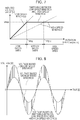
- Fig. 7 is a diagram illustrating the relationship among the rotation speed ⁇ , induced voltage value, and winding state of the AC motor 40.
- the winding switching signal generator 10 outputs the winding switching signal Sa at a low level to the winding switch 60. Accordingly, the winding state of the AC motor 40 becomes the low speed windings.
- the first reference rotation speed ⁇ BL is, for example, a rotation speed ⁇ at which the induced voltage value of the AC motor 40 in the case where the winding state is the low speed windings becomes the maximum voltage value Vmax.
- the winding switching signal generator 10 outputs the winding switching signal Sa at a high level to the winding switch 60. Accordingly, the winding state of the AC motor 40 becomes the state of the high speed windings.
- the second reference rotation speed ⁇ BH is, for example, a rotation speed ⁇ at which the induced voltage value of the AC motor 40 in the case where the winding state is the high speed windings becomes the maximum voltage value Vmax.
- the winding switching signal generator 10 outputs the winding switching signal Sa at a certain frequency (such as 1 kHz) that becomes a high level at a time ratio in accordance with the rotation speed ⁇ to the winding switch 60. Accordingly, the winding state of the AC motor 40 is alternately switched between the low speed windings and the high speed windings.
- the rotation speed ⁇ is greater than the first reference rotation speed ⁇ BL and less than the second reference rotation speed ⁇ BH , if the winding state of the AC motor 40 is the state of the low speed windings, the induced voltage value of the AC motor 40 reaches the maximum voltage value Vmax, and thus, the induced voltage value of the AC motor 40 is maintained at the maximum voltage value Vmax by field weakening control. Meanwhile, if the winding state of the AC motor 40 is the high speed windings, the induced voltage value of the AC motor 40 does not reach the maximum voltage value Vmax.
- the winding state of the AC motor 40 is alternately switched between the low speed windings and the high speed windings, and the induced voltage value of the AC motor 40 is maintained to be less than or equal to the maximum voltage value Vmax without relying on field weakening control.
- a voltage (hereinafter referred to as a medium speed winding voltage) between a voltage based on the low speed windings (hereinafter referred to as a low speed winding voltage) and a voltage based on the high speed windings (hereinafter referred to as a high speed winding voltage) can be generated.
- Fig. 8 is a diagram illustrating an example of the waveform of an output voltage of the inverter device 20 in the case where the winding state of the AC motor 40 is a switching state between the low speed windings and the high speed windings.
- the medium speed winding voltage in a medium speed operation is generated by a voltage based on the low speed winding and a voltage based on the high speed windings, as illustrated in Fig. 8 .
- the medium speed winding voltage can be arbitrarily adjusted between the low speed winding voltage and the high speed winding voltage by adjusting a time in which the winding state of the AC motor 40 is the low speed windings (hereinafter referred to as a low speed winding time) and a time in which the winding state of the AC motor 40 is the high speed windings (hereinafter referred to as a high speed winding time) in a medium speed operation.
- Fig. 9 is a diagram illustrating the relationship between the rotation speed ⁇ and the ON ratio Tr of the winding switching signal Sa.
- the ON ratio Tr is the ratio between a low level and a high level. In the case where the low speed winding time is 100%, the ON ratio Tr is 100%; in the case where the high speed winding time is 100%, the ON ratio Tr is 0%. As illustrated in Fig. 9 , in the case where the rotation speed ⁇ is less than or equal to the first reference rotation speed ⁇ BL , the ON ratio Tr is 100%; in the case where the rotation speed ⁇ is greater than or equal to the second reference rotation speed ⁇ BH , the ON ratio Tr is 0%.
- FIG. 10 is a diagram illustrating an example of the waveform of the winding switching signal Sa. As illustrated in Fig. 10 , for the winding switching signal Sa, an ON period T L in which the winding switching signal Sa is at a low level and an OFF period T H in which the winding switching signal Sa is at a high level are set in every cycle Tc.
- the ON ratio Tr of the winding switching signal Sa is represented by T L /T C .
- the winding switching signal Sa is input to the constant switch 11, as described earlier. Accordingly, setting data in response to the winding switching signal Sa is output from the constant switch 11. Specifically, in the case where the ON ratio Tr of the winding switching signal Sa is 0%, the constant switch 11 switches the switch 23 to the low speed setting data 24, and obtains and outputs setting data from the low speed setting data 24. Meanwhile, in the case where the ON ratio Tr of the winding switching signal Sa is 100%, the constant switch 11 switches the switch 23 to the high speed setting data 26, and obtains and outputs setting data from the high speed setting data 26.
- the constant switch 11 switches the switch 23 to the medium speed setting data table 25.
- the medium speed setting data table 25 setting data in accordance with the ON ratio Tr of the winding switching signal Sa is set.
- the constant switch 11 obtains and outputs setting data in accordance with the ON ratio Tr of the winding switching signal Sa from the medium speed setting data table 25. Accordingly, setting data can be consecutively switched.
- setting data in accordance with the ON ratio Tr of the winding switching signal Sa is set in the table.
- setting data in accordance with the ON ratio Tr of the winding switching signal Sa may be output by an arithmetic operation that calculates setting data in accordance with the ON ratio Tr of the winding switching signal Sa.
- the constant switch 11 outputs setting data in response to the winding switching signal Sa, and the setting data is input to the current command calculator 2. Accordingly, the current command calculator 2 switches to the motor constant and control parameter that match the winding state of the AC motor 40.
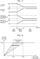
- Fig. 11 is a diagram illustrating the relationship among the ON ratio of the switching elements Sw11 and Sw12 and the time ratio of the low speed windings and the high speed windings in the case where the AC motor 40 is accelerated. As illustrated in Fig. 11 , in the case where the AC motor 40 is accelerated/decelerated, the time ratio of the low speed windings and the time ratio of the high speed windings consecutively change between 0% and 100%, and also setting data output from the constant switch 11 consecutively changes.
- the AC motor 40 can be operated in a manner equivalent to the case in which an AC motor whose characteristics change as illustrated in Fig. 12 is virtually operated.
- Fig. 12 is a diagram illustrating the relationship between the rotation speed ⁇ and induced voltage value of the AC motor 40 in the drive system 100.
- the drive system 100 can further enlarge a highly efficient area by alternately switching the winding state between the low speed windings and the high speed windings at the time ratio in accordance with the rotation speed ⁇ .
- effects caused by switching the windings can be lessened, compared with the case in which the winding state of the AC motor 40 is suddenly switched.
- the winding switching signal generator 10 generates the winding switching signal Sa as a signal synchronized with the carrier wave signal Vt from the PWM signal generator 4. Accordingly, the effect of a switching noise caused by switching the windings can be further suppressed.
- the winding switching signal Sa may be a signal out of synchronization with the carrier wave signal Vt from the PWM signal generator 4, as illustrated in Fig. 13.
- Fig. 13 is a diagram illustrating another configuration of the drive system according to the first embodiment.
- a drive system 100A illustrated in Fig. 13 includes, besides the winding switching signal generator 10 of the inverter device 20, a winding switching signal generator 64 of a winding switch 60A. Accordingly, in the case where the inverter device 20 and the winding switch 60A are at distant places, the drive system 100A can dispense with the work of routing cables, and independent control can be performed.
- the detection timing of the detected current values Iu_fb and Iv_fb detected by the current detector 5 may be concurrent with the winding switching timing of the AC motor 40. Immediately after the windings of the AC motor 40 are switched, if the winding state of the AC motor 40 changes, the accuracy of the detected current values Iu_fb and Iv_fb become deteriorated.
- the controller 22 does not use detected current values Iu_fb and Iv_fb detected by the current detector 5 at the winding switching timing of the AC motor 40, but uses detected current values Iu_fb and Iv_fb detected at one prior timing to generate the voltage commands Vd_ref and Vq_ref. Accordingly, the accuracy deterioration of the voltage output from the power converter 21 can be suppressed.
- the AC motor 40 is operated at a medium speed by performing switching control between the low speed windings and the high speed windings.
- the AC motor 40 is operated in a transition operation.
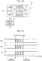
- Fig. 14 is a diagram illustrating the configuration of a controller 22A of the inverter device 20 according to the second embodiment.
- a winding switching signal generator 10A and a constant switch 11A are illustrated, and other configurations are omitted.
- the winding switching signal generator 10A In the case where the rotation speed ⁇ is less than or equal to a reference rotation speed ⁇ BR , the winding switching signal generator 10A outputs a winding switching signal Sa1 at a low level to the winding switch 60. In the case where the rotation speed ⁇ is greater than or equal to the reference rotation speed ⁇ BR , the winding switching signal generator 10A outputs the winding switching signal Sa1 at a high level to the winding switch 60.
- the winding switching signal generator 10A outputs the winding switching signal Sa1 whose time ratio consecutively changes between 0% and 100% in accordance with time to the winding switch 60. Accordingly, while the winding state of the AC motor 40 is alternately switched between the low speed windings and the high speed windings, transition from a low speed operation to a high speed operation and transition from a high speed operation to a low speed operation are performed.
- the winding switching signal Sa1 is a pulse signal at a certain frequency (such as 1 kHz).
- Fig. 15 is a diagram illustrating the state of the switching elements Sw11 and Sw12 and the state of the winding switching signal Sa1 in the case where the AC motor 40 is accelerated from a low speed area to a high speed area.
- the winding switching signal Sa1 is at a low level
- the switching element Sw11 is switched ON
- the switching element Sw12 is switched OFF
- the winding state of the AC motor 40 becomes the low speed windings.
- the time ratio of the winding switching signal Sa1 consecutively changes from 0% to 100% in accordance with time, and the switching elements Sw11 and Sw12 are switched ON/OFF in accordance with the time ratio of the winding switching signal Sa1.
- the winding switching signal Sa1 becomes a high level (time ratio is 100%)
- the switching element Sw11 is switched OFF
- the switching element Sw12 is switched ON
- the winding state of the AC motor 40 becomes the high speed windings.
- the winding switching signal generator 10A executes switching control that alternately switches the winding state between the low speed windings and the high speed windings while shortening the time in which the one type of windings is connected to the power converter 21.
- the constant switch 11A includes a switch 23A, the low speed setting data 24, the high speed setting data 26, and a transition setting data table 27. In the case where the winding switching signal Sa1 is at a low level, the constant switch 11A outputs the low speed setting data 24 from the switch 23A. In the case where the winding switching signal Sa1 is at a high level, the constant switch 11A outputs the high speed setting data 26 from the switch 23A.
- the switch 23A changes setting data set in the transition setting data table 27 and outputs this setting data for a certain period.
- the transition setting data table 27 setting data in accordance with the ON ratio of the winding switching signal Sa1 is set. Accordingly, the constant switch 11A can change and output the setting data for a certain period.
- transition between a low speed operation and a high speed operation is performed while the winding state of the AC motor 40 is alternately switched between the low speed windings and the high speed windings.
- the winding switching signal Sa1 may be a signal out of synchronization with the carrier wave signal Vt from the PWM signal generator 4.
- the winding switching signal generator 64 may be provided in the winding switch 60.
- the controller 22A may not use detected current values Iu_fb and Iv_fb detected by the current detector 5 at the winding switching timing of the AC motor 40, but may use detected current values Iu_fb and Iv_fb detected at one prior timing to generate the voltage commands Vd_ref and Vq_ref.
- connection state of the armature windings is changed by changing the number of windings of a star (Y) connection.
- the connection state of the armature windings is changed by switching between the star connection and a delta ( ⁇ ) connection.
- Fig. 16 is a diagram illustrating the configuration of a drive system 100B according to the third embodiment.
- an AC motor 40B is provided with connection terminals A1 to A6 for extracting two ends of the armature windings for the individual phases.
- a winding switch 60B is connected to these connection terminals A1 to A6.
- the winding switch 60B includes a first switch 61B connected to the connection terminals A4 to A6 of the AC motor 40B, a second switch 62B connected to the connection terminals A1 to A3 of the AC motor 40B, and the logical NOT circuit Inv1. Switches constituting the first switch 61B and the second switch 62B are constituted by, for example, semiconductor elements.
- Fig. 17 is a diagram illustrating an example of each of the switches constituting the first switch 61B and the second switch 62B.
- each switch is configured by an anti-parallel connection of series circuits each including a diode and a switching element.
- this configuration may be different as long as the configuration uses a semiconductor element that can perform high-speed connection/opening for AC voltage current.
- the controller 22 of the inverter device 20 causes the first switch 61B to operate, thereby short-circuiting the termination ends of the armature windings of the AC motor 40B and switching the winding state of the AC motor 40B to a star connection, which corresponds to the low speed windings. Meanwhile, the controller 22 of the inverter device 20 causes the second switch 62B to operate, thereby connecting one ends of the armature windings to the other ends of the armature windings of different phases and switching the winding state of the AC motor 40B to a delta connection, which corresponds to the high speed windings.
- the controller 22 causes the first switch 61B to operate in a low speed operation and causes the second switch 62B to operate in a high speed operation, thereby switching the winding state. Further, as with the case of the first and second embodiments, the controller 22 executes switching control that alternately switches the winding state between the low speed windings and the high speed windings at a time ratio in accordance with the speed of the AC motor 40B in a speed area between a low speed operation based on the low speed windings and a high speed operation based on the high speed windings.
- the drive system 100B according to the third embodiment alternately switches the connection state between the star connection and the delta connection at a time ratio in accordance with the speed of the AC motor 40B, a highly efficient area can be enlarged, as with the cases of the drive system 100 according to the first embodiment.
- the winding state of the armature windings may be switched by changing the number of windings of the delta ⁇ connection.
- the controller 22A may be provided instead of the controller 22. In this case, in transition from a low speed area to a high speed area or in transition from a high speed area to a low speed area, the controller 22A may perform transition between a low speed operation and a high speed operation while alternately switching the winding state of the AC motor 40B between the star connection and the delta connection.
- the winding state of the armature windings is switched by changing the position of a neutral point of the armature windings.
- the winding state of the armature windings is switched without changing the position of the neutral point.
- Fig. 18 is a diagram illustrating the configuration of a drive system 100C according to the fourth embodiment.
- an AC motor 40C is provided with, for the individual phases, connection terminals A1 to A3 for extracting one ends of the armature windings and connection terminals B1 to B3 for extracting the midpoints of the armature windings.
- a winding switch 60C is connected to the connection terminals A1 to A3 and B1 to B3.
- the winding switch 60C includes a first switch 61C connected to the connection terminals A1 to A3 of the AC motor 40C, a second switch 62C connected to the connection terminals B1 to B3 of the AC motor 40C, and the logical NOT circuit Inv1.
- Switches constituting the first switch 61C and the second switch 62C are constituted by semiconductor elements so that connection/opening for AC voltage current can be performed at a high speed (for example, see Fig. 17 ).
- the controller 22 of the inverter device 20 causes the first switch 61C to operate, thereby connecting the connection terminals A1 to A3 of the AC motor 40C to the power converter 21 and switching the winding state of the AC motor 40C. Accordingly, the impedance of the AC motor 40C is maximized. This winding state is called the low speed windings.
- the controller 22 of the inverter device 20 causes the second switch 62C to operate, thereby connecting the connection terminals B1 to B3 of the AC motor 40C to the power converter 21 and switching the winding state of the AC motor 40C. Accordingly, the impedance of the AC motor 40C decreases. This winding state is called the high speed windings.
- the controller 22 causes the first switch 61C to operate in a low speed operation and causes the second switch 62C to operate in a high speed operation, thereby switching the winding state. Further, the controller 22 executes switching control that alternately switches the winding state between the low speed windings and the high speed windings at a time ratio in accordance with the speed of the AC motor 40C in a speed area between a low speed operation based on the low speed windings and a high speed operation based on the high speed windings.
- the drive system 100C according to the fourth embodiment alternately switches the winding state of the star connection between the low speed windings and the high speed windings, as with the case of the drive system 100 according to the first embodiment, a highly efficient area can be enlarged, as with the cases of the drive system 100 according to the first embodiment.
- the controller 22A may be provided instead of the controller 22.
- the controller 22A in transition from a low speed area to a high speed area or in transition from a high speed area to a low speed area, the controller 22A may perform transition between a low speed operation and a high speed operation while alternately switching the winding state between the low speed windings and the high speed windings of the AC motor 40C.
- switching between the two winding states is performed.
- switching among three winding states is performed.
- an example in which the number of windings of the star connection is switched among three levels will be described by way of example. It is only necessary to switch among three or more winding states.
- the number of windings of the delta connection may be switched among three or more levels.
- points different from the drive system 100 according to the first embodiment are mainly discussed, and elements with the same or similar functions as those in the first embodiment are given the same reference numerals, descriptions of which are omitted.
- Fig. 19 is a diagram illustrating the configuration of a drive system 100D according to the fifth embodiment.
- a winding switch 60D is connected to connection terminals A1 to A6 for extracting two ends of the armature windings and connection terminals B1 to B6 provided at middle portions of the armature windings for the individual phases.
- the winding switch 60D includes a first switch 61D connected to the connection terminals A4 to A6 of the AC motor 40D, a second switch 62D connected to the connection terminals B4 to B6 of the AC motor 40D, and a third switch 63D connected to the connection terminals B1 to B3 of the AC motor 40D.
- the first to third switches 61D, 62D, and 63D have the same or similar configuration as the first switch 61 and the second switch 62 (see Fig. 3 ).
- Switches constituting the first to third switches 61D, 62D, and 63D are constituted by semiconductor elements so that connection/opening for AC voltage current can be performed at a high speed (for example, see Fig. 17 ).
- Fig. 20 is a diagram illustrating the relationship between the rotation speed ⁇ and winding state of the AC motor 40D.
- a controller 22D of the inverter device 20D switches the winding state in response to the rotation speed ⁇ among a low speed area, a first medium speed area, a second medium speed area, and a high speed area. This switching is performed by winding switching signals Sa1 to Sa3.
- the controller 22D outputs the winding switching signal Sa1 at a high level and the winding switching signals Sa2 and Sa3 at a low level. Accordingly, the connection terminals A4 to A6 of the AC motor 40D are connected to one another to form a neutral point, and the impedance of the AC motor 40D is maximized.
- the controller 22D In the case of the high speed area in which the rotation speed ⁇ is greater than or equal to a third reference rotation speed ⁇ B2H , the controller 22D outputs the winding switching signal Sa3 at a high level and the winding switching signals Sa1 and Sa2 at a low level. Accordingly, the connection terminals B1 to B3 of the AC motor 40D are connected to one another to form a neutral point, and the impedance of the AC motor 40D is minimized.
- the controller 22D outputs the winding switching signal Sa3 at a low level and the winding switching signals Sa1 and Sa2 which alternately become a high level. Accordingly, the controller 22D executes switching control that alternately switches the winding state between the low speed windings and the first high speed windings at a time ratio in accordance with the speed of the AC motor 40D.
- the first high speed windings correspond to the winding state of the AC motor 40D in the case where the connection terminals B4 to B6 of the AC motor 40D are connected to one another by the second switch 62D to form a neutral point.
- the controller 22D outputs the winding switching signal Sa1 at a low level and the winding switching signals Sa2 and Sa3 which alternately become a high level. Accordingly, the controller 22D executes switching control that alternately switches the winding state between the first high speed windings and second the high speed windings at a time ratio in accordance with the speed of the AC motor 40D.
- the second high speed windings correspond to the winding state of the AC motor 40D in the case where the connection terminals B1 to B3 of the AC motor 40D are connected to one another by the third switch 63D to form a neutral point.
- the drive system 100D can switch the winding state of the AC motor 40D to four states, namely, a state of only the low speed windings, a switching state between the low speed windings and the first high speed windings, a switching state between the first high speed windings and the second high speed windings, and a state of only the high speed windings. Accordingly, a highly efficient area can be further enlarged, compared with the drive systems 100, 100A, and the like according to the above-described embodiments.
- transition of the winding state of the AC motor 40B in the case of transition of the winding state of the AC motor 40B between the low speed windings and the first high speed windings and in the case of transition between the first high speed windings and the second high speed windings, transition of the winding state of the AC motor 40B may be performed while alternately switching the winding state by performing switching control.
- the electric characteristics of the AC motor are switched by switching the winding state of the AC motor.
- the electric characteristics of an AC motor are switched by switching the number of poles of the AC motor.
- Fig. 21 is a diagram illustrating the configuration of a drive system 100E according to the sixth embodiment.
- the drive system 100E includes an inverter device 20E and an AC motor 40E.
- the inverter device 20E includes a power converter 21E and a controller 22E.
- the power converter 21E includes two power converters 51 and 52.
- the power converters 51 and 52 have the same or similar configuration as the power converter 21 (see Fig. 3 ) and are controlled by PWM signals S1 to S6 and S1' to S6' output from the controller 22E.
- the AC motor 40E is a double-winding AC motor with two sets of three-phase armature windings 42 and 43.
- the two sets of three-phase armature windings 42 and 43 are sets of windings with different specifications.
- the power converter 51 is connected to connection terminals A11 to A13 provided at one ends of one set of three-phase armature windings 42
- the power converter 52 is connected to connection terminals A21 to A23 provided at one ends of the other set of three-phase armature windings 43.
- the controller 22E of the inverter device 20E can cause the AC motor 40E to operate as a 2n-pole (such as four-pole) motor by supplying homopolar currents from the two power converters 51 and 52 to the two sets of three-phase armature windings 42 and 43.
- the controller 22E can cause the AC motor 40E to operate as an n-pole (such as two-pole) motor by supplying antipolar currents from the two power converters 51 and 52 to the two sets of three-phase armature windings 42 and 43.
- the drive system 100E drives the two sets of three-phase armature windings 42 and 43 with different specifications included in one AC motor 40E by the two power converters 51 and 52, and switches the number of poles of the motor by switching a combination of current vectors. Because the technology of switching the number of poles of a motor is publicly known technology as described in IEEE Transactions on Industry Applications, Vol. 32d No. 4, July/August, 1996, pp. 938-944 , for example, a description thereof is omitted here.
- the controller 22E supplies homopolar currents from the two power converters 51 and 52 to the two sets of three-phase armature windings 42 and 43.
- the AC motor 40E operates as a 2n-pole (an example of the number of poles for low speed) motor, the electric characteristics of the AC motor 40E become low speed characteristics in which the number of poles is great.
- the controller 22E supplies antipolar currents from the two power converters 51 and 52 to the two sets of three-phase armature windings 42 and 43.
- the AC motor 40E operates as an n-pole (an example of the number of poles for high speed) motor, the electric characteristics of the AC motor 40E become high speed characteristics in which the number of poles is small.
- the controller 22E switches the winding state between a state in which the controller 22E supplies homopolar currents to the two sets of three-phase armature windings 42 and 43 and a state in which the controller 22E supplies antipolar currents to the two sets of three-phase armature windings 42 and 43 at a time ratio in accordance with the speed of the AC motor 40E.
- the drive system 100E executes switching control that alternately switches the number of poles of the AC motor 40E between 2n-poles and n-poles of the AC motor 40E at a time ratio in accordance with the speed of the AC motor 40E. Therefore, even during acceleration or deceleration, fluctuations of the electric characteristics of the AC motor 40E can be suppressed, and effects caused by switching of the electric characteristics of the AC motor 40E can be suppressed. In addition, a highly efficient area can be enlarged.
- transition between a low speed operation and a high speed operation may be performed while alternately switching the number of poles between the number of poles for low speed and the number of poles for high speed of the AC motor 40E.
- the AC motor 40 may be a double-winding AC motor in which the low speed windings and the high speed windings are separate sets of windings.
- the inverter device 20 is described as a voltage-source inverter in the above-described embodiments, the inverter device 20 may be a current-source inverter.
Landscapes
- Engineering & Computer Science (AREA)
- Power Engineering (AREA)
- Control Of Ac Motors In General (AREA)
Claims (8)
- Dispositif inverseur (20, 20D, 20E) comprenant :une unité d'alimentation (21, 21E) qui alimente en courant alternatif (AC) un moteur AC (40, 40B à 40E) dont les caractéristiques électriques en réponse à une vitesse de rotation (ω) sont commutables entre des caractéristiques de basse vitesse et des caractéristiques de haute vitesse ; etun contrôleur de commutation (10, 11, 22, 60) qui commute les caractéristiques électriques du moteur AC (40, 40B à 40E),dans lequel le contrôleur de commutation (10, 11, 22, 60) exécute le contrôle de commutation qui commute alternativement les caractéristiques électriques du moteur AC (40, 40B à 40E) entre les caractéristiques de basse vitesse et les caractéristiques de haute vitesse sur la base de la vitesse de rotation (ω) du moteur AC (40, 40B à 40E),dans lequel, dans le cas où la vitesse de rotation (ω) du moteur AC (40, 40B à 40E) se trouve dans une zone déterminée, le contrôleur de commutation (10, 11, 22, 60) exécute le contrôle de commutation avec un ratio de temps en fonction de la vitesse de rotation (ω) du moteur AC (40, 40B à 40E).
- Dispositif inverseur (20, 20D, 20E) selon la revendication 1, dans lequel, dans le cas d'une transition des caractéristiques électriques du moteur AC (40, 40B à 40E) d'un état caractéristique des caractéristiques basse vitesse et des caractéristiques haute vitesse à l'autre état caractéristique, le contrôleur de commutation (10, 11, 22, 60) exécute le contrôle de commutation qui commute alternativement les caractéristiques électriques du moteur AC entre un état caractéristique et l'autre état caractéristique tout en raccourcissant un temps de l'état caractéristique.
- Dispositif inverseur (20, 20D, 20E) selon l'une des revendications 1 à 2,
dans lequel les caractéristiques électriques du moteur AC (40, 40B à 40E) sont commutables en commutant l'état d'enroulement entre un enroulement à basse vitesse et un enroulement à haute vitesse et
dans lequel le contrôleur de commutation (10, 11, 22, 60) exécute un contrôle de commutation qui commute alternativement l'état d'enroulement du moteur AC (40, 40B à 40E) entre l'enroulement à basse vitesse et l'enroulement à haute vitesse sur la base de la vitesse de rotation (ω) du moteur AC (40, 40B à 40E). - Dispositif inverseur (20, 20D, 20E) selon l'une des revendications 1 à 2,
dans lequel les caractéristiques électriques du moteur AC (40, 40B à 40E) sont commutables en commutant le nombre de pôles et
dans lequel le contrôleur de commutation (10, 11, 22, 60) exécute un contrôle de commutation qui commute alternativement le nombre de pôles du moteur AC (40, 40B à 40E) entre le nombre de pôles pour la basse vitesse et le nombre de pôles pour la haute vitesse sur la base de la vitesse de rotation (ω) du moteur AC (40, 40B à 40E). - Dispositif inverseur (20, 20D, 20E) selon l'une des revendications 1 à 4,
dans lequel l'unité d'alimentation (21, 21E) comprend
un convertisseur de puissance comprenant un élément de commutation (Sw1 à Sw6) et
un générateur de signal (4) à modulation phase-largeur (PWM) qui génère un signal PWM (S1 à S6) sur la base d'une comparaison entre une commande de tension (Vu_ref, Vv_ref, Vw_ref) et une onde porteuse (Vt) et qui contrôle l'élément de commutation (Sw1 à Sw6) et
dans lequel le contrôleur de commutation (10, 11, 22, 60) exécute le contrôle de commutation en synchronisation avec l'onde porteuse (Vt). - Dispositif inverseur (20, 20D, 20E) selon l'une des revendications 1 à 4,
dans lequel l'unité d'alimentation (21, 21E) comprend
un convertisseur de puissance comprenant un élément de commutation (Sw1 à Sw6) et
un générateur de signal (4) à modulation phase-largeur (PWM) qui génère un signal PWM (S1 à S6) sur la base d'une comparaison entre une commande de tension (Vu_ref, Vv_ref, Vw_ref) et une onde porteuse (Vt) et qui contrôle l'élément de commutation (Sw1 à Sw6) et
dans lequel le contrôleur de commutation (10, 11, 22, 60) exécute le contrôle de commutation de manière non synchronisée avec l'onde porteuse (Vt). - Dispositif inverseur (20, 20D, 20E) selon la revendication 5 ou 6, comprenant en outre un générateur de commande (2, 3) qui génère la commande de tension (Vu_ref, Vv_ref, Vw_ref) à partir d'une commande de couple (T_ref) sur la base de données de réglage (24, 25, 26) comprenant une constante de moteur et un paramètre de contrôle,
dans lequel le contrôleur de commutation (10, 11, 22, 60) obtient les données de réglage (24, 25, 26) en fonction du contrôle de commutation à l'aide d'une table ou d'une opération arithmétique et envoie les données de réglage (24, 25, 26) au générateur de commande. - Système de commande de moteur (100, 100A à 100E), comprenant :un moteur (40, 40B à 40E) à courant alternatif (AC) dont les caractéristiques électriques en réponse à une vitesse de rotation (ω) sont commutables entre des caractéristiques de basse vitesse et des caractéristiques de haute vitesse ;une unité d'alimentation (21, 21E) qui alimente le moteur AC (40, 40B, à 40E) en puissance AC ; etun contrôleur de commutation (10, 11, 22, 60) qui commute les caractéristiques électriques du moteur AC (40, 40B à 40E),dans lequel le contrôleur de commutation (10, 11, 22, 60) exécute le contrôle de commutation qui commute alternativement les caractéristiques électriques du moteur AC (40, 40B à 40E) entre les caractéristiques de basse vitesse et les caractéristiques de haute vitesse sur la base de la vitesse de rotation (ω) du moteur AC (40, 40B à 40E),dans lequel, dans le cas où la vitesse de rotation (ω) du moteur AC (40, 40B à 40E) se trouve dans une zone déterminée, le contrôleur de commutation (10, 11, 22, 60) exécute le contrôle de commutation avec un ratio de temps en fonction de la vitesse de rotation (ω) du moteur AC (40, 40B à 40E).
Applications Claiming Priority (1)
| Application Number | Priority Date | Filing Date | Title |
|---|---|---|---|
| JP2013018808A JP5569606B1 (ja) | 2013-02-01 | 2013-02-01 | インバータ装置および電動機ドライブシステム |
Publications (3)
| Publication Number | Publication Date |
|---|---|
| EP2763310A2 EP2763310A2 (fr) | 2014-08-06 |
| EP2763310A3 EP2763310A3 (fr) | 2017-06-28 |
| EP2763310B1 true EP2763310B1 (fr) | 2018-10-10 |
Family
ID=49917522
Family Applications (1)
| Application Number | Title | Priority Date | Filing Date |
|---|---|---|---|
| EP13199869.2A Not-in-force EP2763310B1 (fr) | 2013-02-01 | 2013-12-31 | Dispositif de contrôle d'inverseur et système d'entraînement de moteur |
Country Status (4)
| Country | Link |
|---|---|
| US (1) | US9252698B2 (fr) |
| EP (1) | EP2763310B1 (fr) |
| JP (1) | JP5569606B1 (fr) |
| CN (1) | CN103973200B (fr) |
Cited By (1)
| Publication number | Priority date | Publication date | Assignee | Title |
|---|---|---|---|---|
| EP4002681B1 (fr) | 2020-11-12 | 2024-05-22 | Valeo eAutomotive Germany GmbH | Onduleur, entraînement électrique, véhicule et procédé de commande de commutateurs réglables d'un onduleur et produit programme informatique correspondant |
Families Citing this family (34)
| Publication number | Priority date | Publication date | Assignee | Title |
|---|---|---|---|---|
| JP5476407B2 (ja) * | 2012-03-14 | 2014-04-23 | 株式会社安川電機 | モータ駆動装置および車両 |
| US20150171777A1 (en) * | 2013-12-18 | 2015-06-18 | Hyundai Motor Company | Method for controlling driving motor |
| JP2015211597A (ja) * | 2014-04-28 | 2015-11-24 | 日本電産株式会社 | 電動機駆動システム |
| KR101654707B1 (ko) * | 2014-11-18 | 2016-09-06 | 현대모비스 주식회사 | 차량용 전기 모터 시스템 및 차량용 전기 모터의 권선 턴수를 가변하는 방법 |
| CN104779892B (zh) * | 2015-04-02 | 2017-09-26 | 福州大学 | 基于y‑△变换扩大交流电动机恒转矩变频调速范围的系统与方法 |
| JP6279151B2 (ja) * | 2015-04-27 | 2018-02-14 | 三菱電機株式会社 | 交流回転機の制御装置および電動パワーステアリング装置 |
| JP6630561B2 (ja) * | 2015-12-15 | 2020-01-15 | 三菱重工業株式会社 | モータの巻線切替スイッチを備えたモータ用駆動制御装置、モータ、コンプレッサ、およびモータ巻線切替制御方法 |
| DE102016200112A1 (de) * | 2016-01-07 | 2017-07-13 | Leybold Gmbh | Vakuumpumpenantrieb mit Stern-Dreieck-Umschaltung |
| GB2549086B (en) | 2016-03-30 | 2022-09-07 | Advanced Electric Machines Group Ltd | Electrical sub-assembly |
| JP6180669B1 (ja) * | 2016-07-04 | 2017-08-16 | 三菱電機株式会社 | 極数切替型回転電機および極数切替型回転電機の駆動方法 |
| CN107591923B (zh) * | 2016-07-07 | 2020-03-20 | 张世兴 | 一种变功率电动机 |
| US11509251B2 (en) | 2016-10-31 | 2022-11-22 | Mitsubishi Electric Corporation | Motor driving device and air conditioner |
| CN109863691B (zh) * | 2016-10-31 | 2023-04-04 | 三菱电机株式会社 | 空气调和机以及空气调和机的控制方法 |
| JP6625762B2 (ja) * | 2016-10-31 | 2019-12-25 | 三菱電機株式会社 | 駆動装置、空気調和機および電動機の駆動方法 |
| CN110915130B (zh) * | 2017-07-07 | 2023-12-08 | 三菱电机株式会社 | 马达驱动系统以及空调机 |
| EP3661047B1 (fr) * | 2017-07-28 | 2022-11-23 | Mitsubishi Electric Corporation | Dispositif d'entraînement, compresseur, climatiseur et procédé de commande d'un moteur électrique de type à aimant permanent intégré |
| US10320220B2 (en) * | 2017-08-23 | 2019-06-11 | Ford Global Technologies, Llc | Configurable hybrid drive systems |
| JP6787300B2 (ja) * | 2017-11-22 | 2020-11-18 | トヨタ自動車株式会社 | スイッチトリラクタンスモータの制御装置 |
| CN108258965B (zh) * | 2018-01-03 | 2020-06-30 | 广东美芝制冷设备有限公司 | Pi控制器限幅值的控制方法、系统和永磁同步电机 |
| CN108336928B (zh) * | 2018-01-03 | 2020-05-19 | 广东美芝制冷设备有限公司 | 永磁同步电机定子绕组的切换方法、装置及计算机设备 |
| JP6929434B2 (ja) * | 2018-02-26 | 2021-09-01 | 三菱電機株式会社 | 電動機駆動装置及び冷凍サイクル適用機器 |
| JP7033958B2 (ja) * | 2018-03-02 | 2022-03-11 | 株式会社日立製作所 | 回転機駆動システム |
| CN111837332A (zh) * | 2018-03-08 | 2020-10-27 | 三菱电机株式会社 | 电动机驱动装置以及空调机 |
| CN108390488A (zh) * | 2018-05-14 | 2018-08-10 | 西安清泰科新能源技术有限责任公司 | 一种三相电机绕组切换装置及控制方法 |
| CN111886791A (zh) * | 2018-05-22 | 2020-11-03 | 松下知识产权经营株式会社 | 电动机驱动装置和使用它的冷藏库 |
| JP7335258B2 (ja) * | 2018-09-28 | 2023-08-29 | 三菱電機株式会社 | モータ駆動装置及び空気調和機 |
| CN109951132A (zh) * | 2019-04-18 | 2019-06-28 | 苏州阿福机器人有限公司 | 一种用于电机线圈串并联转换的电路 |
| US10917030B1 (en) * | 2019-09-13 | 2021-02-09 | GM Global Technology Operations LLC | Electric drive system with reconfigurable machine windings |
| US10998840B2 (en) * | 2019-09-13 | 2021-05-04 | GM Global Technology Operations LLC | Electric drive system with reconfigurable machine windings |
| EP3799293B1 (fr) * | 2019-09-25 | 2023-12-27 | Schneider Toshiba Inverter Europe SAS | Entraînement à vitesse variable pour le contrôle pwm sans capteur d'un moteur à courant alternatif par l'exploitation d'artéfacts induits par pwm |
| US11218096B2 (en) * | 2019-11-29 | 2022-01-04 | Steering Solutions Ip Holding Corporation | Feedforward control of multiphase permanent magnet direct current motor drives |
| US11183960B1 (en) * | 2020-08-27 | 2021-11-23 | Honeywell International Inc. | Fail-safe motor control architecture for open-end winding motors |
| CN112865658B (zh) * | 2021-01-13 | 2022-02-01 | 天津民昌科技有限公司 | 一种变频变拓扑调速电机控制系统 |
| US11870237B2 (en) * | 2021-03-05 | 2024-01-09 | Proterial, Ltd. | Surge suppression circuit and rotating electrical machine |
Family Cites Families (25)
| Publication number | Priority date | Publication date | Assignee | Title |
|---|---|---|---|---|
| US4453118A (en) * | 1982-11-08 | 1984-06-05 | Century Electric, Inc. | Starting control circuit for a multispeed A.C. motor |
| US4712054A (en) * | 1986-05-14 | 1987-12-08 | East Moline Metal Products Company | Controller with two modes of braking induction motors |
| JPH0255599A (ja) * | 1988-08-19 | 1990-02-23 | Fanuc Ltd | 巻線切替型の交流電動機 |
| US5216343A (en) * | 1991-04-30 | 1993-06-01 | Seagate Technology, Inc. | Motor construction and method for limiting spin-up time in a hard disk drive |
| JPH053694A (ja) * | 1991-06-26 | 1993-01-08 | Yaskawa Electric Corp | 同期電動機の駆動方法 |
| JPH0527845A (ja) * | 1991-07-22 | 1993-02-05 | Okuma Mach Works Ltd | 制御パラメータ変更機能を有する数値制御装置 |
| JPH06225588A (ja) | 1993-01-21 | 1994-08-12 | Toyota Motor Corp | 巻線切替式永久磁石モータの制御装置 |
| US5821722A (en) * | 1995-06-06 | 1998-10-13 | General Electric Company | Multiphase electrical motor, control and method using overlapping conduction periods in the windings |
| US5883488A (en) * | 1996-07-26 | 1999-03-16 | Emerson Electric Co. | Method and apparatus for multispeed hybrid start switch for a motor |
| JP3948009B2 (ja) * | 2001-10-03 | 2007-07-25 | 株式会社安川電機 | 3相交流電動機の巻線切換装置 |
| JP2004343862A (ja) * | 2003-05-14 | 2004-12-02 | Matsushita Electric Ind Co Ltd | モータ制御装置 |
| US7224557B2 (en) * | 2003-06-28 | 2007-05-29 | Eaton Corporation | Method and system of controlling asynchronous contactors for a multi-phase electric load |
| JP2005042684A (ja) * | 2003-07-25 | 2005-02-17 | Denso Corp | 電動機付ターボチャージャの電力制御装置および電動ターボチャージャ装置 |
| CN101535913B (zh) * | 2006-10-31 | 2011-03-02 | 比亚迪股份有限公司 | 电动机控制方法 |
| WO2009084354A1 (fr) * | 2007-12-27 | 2009-07-09 | Kabushiki Kaisha Yaskawa Denki | Dispositif de commutation des enroulements d'un moteur ca triphasé |
| JP5243869B2 (ja) * | 2008-07-14 | 2013-07-24 | 株式会社安川電機 | 交流電動機の巻線切換装置およびインバータ装置 |
| JP5493220B2 (ja) * | 2009-08-26 | 2014-05-14 | 株式会社安川電機 | 電動機駆動方法および電動車両用駆動装置 |
| JP5471259B2 (ja) * | 2009-10-02 | 2014-04-16 | アイシン・エィ・ダブリュ株式会社 | 制御装置 |
| US8039982B2 (en) * | 2010-06-29 | 2011-10-18 | General Electric Company | Method for operating a wind turbine, coil arrangement for an electric machine, and controller for a wind turbine |
| CN102074758B (zh) * | 2010-07-30 | 2012-06-20 | 比亚迪股份有限公司 | 一种电池的加热电路 |
| JP5615089B2 (ja) * | 2010-08-18 | 2014-10-29 | 株式会社松井製作所 | 電動機駆動トルク制御装置及び電動機駆動トルク制御方法 |
| JP5707206B2 (ja) * | 2011-04-04 | 2015-04-22 | 株式会社アマダ | 加工機のテーブル駆動装置 |
| JP5382069B2 (ja) * | 2011-07-04 | 2014-01-08 | 株式会社安川電機 | インバータ装置および電動機ドライブシステム |
| JP5978638B2 (ja) * | 2012-02-03 | 2016-08-24 | 株式会社安川電機 | 回転電機システム |
| JP5549751B1 (ja) * | 2013-01-31 | 2014-07-16 | 株式会社安川電機 | インバータ装置、インバータ装置の制御方法、及び電動機ドライブシステム |
-
2013
- 2013-02-01 JP JP2013018808A patent/JP5569606B1/ja not_active Expired - Fee Related
- 2013-12-26 CN CN201310737925.XA patent/CN103973200B/zh not_active Expired - Fee Related
- 2013-12-31 EP EP13199869.2A patent/EP2763310B1/fr not_active Not-in-force
-
2014
- 2014-01-24 US US14/162,740 patent/US9252698B2/en not_active Expired - Fee Related
Non-Patent Citations (1)
| Title |
|---|
| None * |
Cited By (1)
| Publication number | Priority date | Publication date | Assignee | Title |
|---|---|---|---|---|
| EP4002681B1 (fr) | 2020-11-12 | 2024-05-22 | Valeo eAutomotive Germany GmbH | Onduleur, entraînement électrique, véhicule et procédé de commande de commutateurs réglables d'un onduleur et produit programme informatique correspondant |
Also Published As
| Publication number | Publication date |
|---|---|
| EP2763310A2 (fr) | 2014-08-06 |
| US9252698B2 (en) | 2016-02-02 |
| JP5569606B1 (ja) | 2014-08-13 |
| CN103973200B (zh) | 2016-06-22 |
| JP2014150685A (ja) | 2014-08-21 |
| US20140217946A1 (en) | 2014-08-07 |
| EP2763310A3 (fr) | 2017-06-28 |
| CN103973200A (zh) | 2014-08-06 |
Similar Documents
| Publication | Publication Date | Title |
|---|---|---|
| US9252698B2 (en) | Inverter device and motor drive system | |
| US9184688B2 (en) | Inverter device and electric motor drive system | |
| JP5870591B2 (ja) | 同期電動機の制御装置及び制御方法 | |
| JP5549751B1 (ja) | インバータ装置、インバータ装置の制御方法、及び電動機ドライブシステム | |
| US8441225B2 (en) | Direct-current to three-phase alternating-current inverter system | |
| WO2014087640A9 (fr) | Dispositif de commande de moteur | |
| US20150097505A1 (en) | Current source inverter device | |
| US8736221B2 (en) | Direct-current to three-phase alternating-current inverter system | |
| US9231514B2 (en) | Motor control apparatus and motor control method | |
| JP6983305B2 (ja) | 車両制御装置 | |
| WO2020196719A1 (fr) | Système de commande de machine électrique rotative | |
| JP6951945B2 (ja) | モータ制御装置及びモータ制御方法 | |
| JP6716041B2 (ja) | 電力変換装置および電動パワーステアリング装置 | |
| JP2017005895A (ja) | 回転機の制御装置 | |
| JP7759617B2 (ja) | 回転電機の制御装置、及びプログラム | |
| JP2016025694A (ja) | 永久磁石式同期モータの制御装置 |
Legal Events
| Date | Code | Title | Description |
|---|---|---|---|
| PUAI | Public reference made under article 153(3) epc to a published international application that has entered the european phase |
Free format text: ORIGINAL CODE: 0009012 |
|
| 17P | Request for examination filed |
Effective date: 20131231 |
|
| AK | Designated contracting states |
Kind code of ref document: A2 Designated state(s): AL AT BE BG CH CY CZ DE DK EE ES FI FR GB GR HR HU IE IS IT LI LT LU LV MC MK MT NL NO PL PT RO RS SE SI SK SM TR |
|
| AX | Request for extension of the european patent |
Extension state: BA ME |
|
| PUAL | Search report despatched |
Free format text: ORIGINAL CODE: 0009013 |
|
| AK | Designated contracting states |
Kind code of ref document: A3 Designated state(s): AL AT BE BG CH CY CZ DE DK EE ES FI FR GB GR HR HU IE IS IT LI LT LU LV MC MK MT NL NO PL PT RO RS SE SI SK SM TR |
|
| AX | Request for extension of the european patent |
Extension state: BA ME |
|
| RIC1 | Information provided on ipc code assigned before grant |
Ipc: H02P 6/08 20160101AFI20170524BHEP Ipc: H02P 25/18 20060101ALI20170524BHEP |
|
| R17P | Request for examination filed (corrected) |
Effective date: 20171211 |
|
| RBV | Designated contracting states (corrected) |
Designated state(s): AL AT BE BG CH CY CZ DE DK EE ES FI FR GB GR HR HU IE IS IT LI LT LU LV MC MK MT NL NO PL PT RO RS SE SI SK SM TR |
|
| GRAP | Despatch of communication of intention to grant a patent |
Free format text: ORIGINAL CODE: EPIDOSNIGR1 |
|
| INTG | Intention to grant announced |
Effective date: 20180508 |
|
| GRAS | Grant fee paid |
Free format text: ORIGINAL CODE: EPIDOSNIGR3 |
|
| GRAA | (expected) grant |
Free format text: ORIGINAL CODE: 0009210 |
|
| AK | Designated contracting states |
Kind code of ref document: B1 Designated state(s): AL AT BE BG CH CY CZ DE DK EE ES FI FR GB GR HR HU IE IS IT LI LT LU LV MC MK MT NL NO PL PT RO RS SE SI SK SM TR |
|
| REG | Reference to a national code |
Ref country code: GB Ref legal event code: FG4D |
|
| REG | Reference to a national code |
Ref country code: CH Ref legal event code: EP Ref country code: AT Ref legal event code: REF Ref document number: 1052419 Country of ref document: AT Kind code of ref document: T Effective date: 20181015 |
|
| REG | Reference to a national code |
Ref country code: IE Ref legal event code: FG4D |
|
| REG | Reference to a national code |
Ref country code: DE Ref legal event code: R096 Ref document number: 602013044795 Country of ref document: DE |
|
| REG | Reference to a national code |
Ref country code: NL Ref legal event code: MP Effective date: 20181010 |
|
| REG | Reference to a national code |
Ref country code: LT Ref legal event code: MG4D |
|
| REG | Reference to a national code |
Ref country code: AT Ref legal event code: MK05 Ref document number: 1052419 Country of ref document: AT Kind code of ref document: T Effective date: 20181010 |
|
| PG25 | Lapsed in a contracting state [announced via postgrant information from national office to epo] |
Ref country code: NL Free format text: LAPSE BECAUSE OF FAILURE TO SUBMIT A TRANSLATION OF THE DESCRIPTION OR TO PAY THE FEE WITHIN THE PRESCRIBED TIME-LIMIT Effective date: 20181010 |
|
| PG25 | Lapsed in a contracting state [announced via postgrant information from national office to epo] |
Ref country code: IS Free format text: LAPSE BECAUSE OF FAILURE TO SUBMIT A TRANSLATION OF THE DESCRIPTION OR TO PAY THE FEE WITHIN THE PRESCRIBED TIME-LIMIT Effective date: 20190210 Ref country code: BG Free format text: LAPSE BECAUSE OF FAILURE TO SUBMIT A TRANSLATION OF THE DESCRIPTION OR TO PAY THE FEE WITHIN THE PRESCRIBED TIME-LIMIT Effective date: 20190110 Ref country code: ES Free format text: LAPSE BECAUSE OF FAILURE TO SUBMIT A TRANSLATION OF THE DESCRIPTION OR TO PAY THE FEE WITHIN THE PRESCRIBED TIME-LIMIT Effective date: 20181010 Ref country code: LT Free format text: LAPSE BECAUSE OF FAILURE TO SUBMIT A TRANSLATION OF THE DESCRIPTION OR TO PAY THE FEE WITHIN THE PRESCRIBED TIME-LIMIT Effective date: 20181010 Ref country code: HR Free format text: LAPSE BECAUSE OF FAILURE TO SUBMIT A TRANSLATION OF THE DESCRIPTION OR TO PAY THE FEE WITHIN THE PRESCRIBED TIME-LIMIT Effective date: 20181010 Ref country code: NO Free format text: LAPSE BECAUSE OF FAILURE TO SUBMIT A TRANSLATION OF THE DESCRIPTION OR TO PAY THE FEE WITHIN THE PRESCRIBED TIME-LIMIT Effective date: 20190110 Ref country code: PL Free format text: LAPSE BECAUSE OF FAILURE TO SUBMIT A TRANSLATION OF THE DESCRIPTION OR TO PAY THE FEE WITHIN THE PRESCRIBED TIME-LIMIT Effective date: 20181010 Ref country code: AT Free format text: LAPSE BECAUSE OF FAILURE TO SUBMIT A TRANSLATION OF THE DESCRIPTION OR TO PAY THE FEE WITHIN THE PRESCRIBED TIME-LIMIT Effective date: 20181010 Ref country code: LV Free format text: LAPSE BECAUSE OF FAILURE TO SUBMIT A TRANSLATION OF THE DESCRIPTION OR TO PAY THE FEE WITHIN THE PRESCRIBED TIME-LIMIT Effective date: 20181010 Ref country code: FI Free format text: LAPSE BECAUSE OF FAILURE TO SUBMIT A TRANSLATION OF THE DESCRIPTION OR TO PAY THE FEE WITHIN THE PRESCRIBED TIME-LIMIT Effective date: 20181010 |
|
| PG25 | Lapsed in a contracting state [announced via postgrant information from national office to epo] |
Ref country code: SE Free format text: LAPSE BECAUSE OF FAILURE TO SUBMIT A TRANSLATION OF THE DESCRIPTION OR TO PAY THE FEE WITHIN THE PRESCRIBED TIME-LIMIT Effective date: 20181010 Ref country code: AL Free format text: LAPSE BECAUSE OF FAILURE TO SUBMIT A TRANSLATION OF THE DESCRIPTION OR TO PAY THE FEE WITHIN THE PRESCRIBED TIME-LIMIT Effective date: 20181010 Ref country code: RS Free format text: LAPSE BECAUSE OF FAILURE TO SUBMIT A TRANSLATION OF THE DESCRIPTION OR TO PAY THE FEE WITHIN THE PRESCRIBED TIME-LIMIT Effective date: 20181010 Ref country code: GR Free format text: LAPSE BECAUSE OF FAILURE TO SUBMIT A TRANSLATION OF THE DESCRIPTION OR TO PAY THE FEE WITHIN THE PRESCRIBED TIME-LIMIT Effective date: 20190111 Ref country code: PT Free format text: LAPSE BECAUSE OF FAILURE TO SUBMIT A TRANSLATION OF THE DESCRIPTION OR TO PAY THE FEE WITHIN THE PRESCRIBED TIME-LIMIT Effective date: 20190210 |
|
| REG | Reference to a national code |
Ref country code: DE Ref legal event code: R097 Ref document number: 602013044795 Country of ref document: DE |
|
| PG25 | Lapsed in a contracting state [announced via postgrant information from national office to epo] |
Ref country code: IT Free format text: LAPSE BECAUSE OF FAILURE TO SUBMIT A TRANSLATION OF THE DESCRIPTION OR TO PAY THE FEE WITHIN THE PRESCRIBED TIME-LIMIT Effective date: 20181010 Ref country code: DK Free format text: LAPSE BECAUSE OF FAILURE TO SUBMIT A TRANSLATION OF THE DESCRIPTION OR TO PAY THE FEE WITHIN THE PRESCRIBED TIME-LIMIT Effective date: 20181010 Ref country code: CZ Free format text: LAPSE BECAUSE OF FAILURE TO SUBMIT A TRANSLATION OF THE DESCRIPTION OR TO PAY THE FEE WITHIN THE PRESCRIBED TIME-LIMIT Effective date: 20181010 |
|
| REG | Reference to a national code |
Ref country code: CH Ref legal event code: PL |
|
| PLBE | No opposition filed within time limit |
Free format text: ORIGINAL CODE: 0009261 |
|
| STAA | Information on the status of an ep patent application or granted ep patent |
Free format text: STATUS: NO OPPOSITION FILED WITHIN TIME LIMIT |
|
| PG25 | Lapsed in a contracting state [announced via postgrant information from national office to epo] |
Ref country code: SM Free format text: LAPSE BECAUSE OF FAILURE TO SUBMIT A TRANSLATION OF THE DESCRIPTION OR TO PAY THE FEE WITHIN THE PRESCRIBED TIME-LIMIT Effective date: 20181010 Ref country code: EE Free format text: LAPSE BECAUSE OF FAILURE TO SUBMIT A TRANSLATION OF THE DESCRIPTION OR TO PAY THE FEE WITHIN THE PRESCRIBED TIME-LIMIT Effective date: 20181010 Ref country code: SK Free format text: LAPSE BECAUSE OF FAILURE TO SUBMIT A TRANSLATION OF THE DESCRIPTION OR TO PAY THE FEE WITHIN THE PRESCRIBED TIME-LIMIT Effective date: 20181010 Ref country code: RO Free format text: LAPSE BECAUSE OF FAILURE TO SUBMIT A TRANSLATION OF THE DESCRIPTION OR TO PAY THE FEE WITHIN THE PRESCRIBED TIME-LIMIT Effective date: 20181010 Ref country code: MC Free format text: LAPSE BECAUSE OF FAILURE TO SUBMIT A TRANSLATION OF THE DESCRIPTION OR TO PAY THE FEE WITHIN THE PRESCRIBED TIME-LIMIT Effective date: 20181010 Ref country code: LU Free format text: LAPSE BECAUSE OF NON-PAYMENT OF DUE FEES Effective date: 20181231 |
|
| 26N | No opposition filed |
Effective date: 20190711 |
|
| GBPC | Gb: european patent ceased through non-payment of renewal fee |
Effective date: 20190110 |
|
| REG | Reference to a national code |
Ref country code: BE Ref legal event code: MM Effective date: 20181231 Ref country code: IE Ref legal event code: MM4A |
|
| PG25 | Lapsed in a contracting state [announced via postgrant information from national office to epo] |
Ref country code: SI Free format text: LAPSE BECAUSE OF FAILURE TO SUBMIT A TRANSLATION OF THE DESCRIPTION OR TO PAY THE FEE WITHIN THE PRESCRIBED TIME-LIMIT Effective date: 20181010 Ref country code: IE Free format text: LAPSE BECAUSE OF NON-PAYMENT OF DUE FEES Effective date: 20181231 Ref country code: FR Free format text: LAPSE BECAUSE OF NON-PAYMENT OF DUE FEES Effective date: 20181231 |
|
| PG25 | Lapsed in a contracting state [announced via postgrant information from national office to epo] |
Ref country code: BE Free format text: LAPSE BECAUSE OF NON-PAYMENT OF DUE FEES Effective date: 20181231 |
|
| PG25 | Lapsed in a contracting state [announced via postgrant information from national office to epo] |
Ref country code: GB Free format text: LAPSE BECAUSE OF NON-PAYMENT OF DUE FEES Effective date: 20190110 Ref country code: CH Free format text: LAPSE BECAUSE OF NON-PAYMENT OF DUE FEES Effective date: 20181231 Ref country code: LI Free format text: LAPSE BECAUSE OF NON-PAYMENT OF DUE FEES Effective date: 20181231 |
|
| PG25 | Lapsed in a contracting state [announced via postgrant information from national office to epo] |
Ref country code: MT Free format text: LAPSE BECAUSE OF NON-PAYMENT OF DUE FEES Effective date: 20181231 |
|
| PG25 | Lapsed in a contracting state [announced via postgrant information from national office to epo] |
Ref country code: TR Free format text: LAPSE BECAUSE OF FAILURE TO SUBMIT A TRANSLATION OF THE DESCRIPTION OR TO PAY THE FEE WITHIN THE PRESCRIBED TIME-LIMIT Effective date: 20181010 |
|
| PG25 | Lapsed in a contracting state [announced via postgrant information from national office to epo] |
Ref country code: CY Free format text: LAPSE BECAUSE OF FAILURE TO SUBMIT A TRANSLATION OF THE DESCRIPTION OR TO PAY THE FEE WITHIN THE PRESCRIBED TIME-LIMIT Effective date: 20181010 Ref country code: MK Free format text: LAPSE BECAUSE OF NON-PAYMENT OF DUE FEES Effective date: 20181010 Ref country code: HU Free format text: LAPSE BECAUSE OF FAILURE TO SUBMIT A TRANSLATION OF THE DESCRIPTION OR TO PAY THE FEE WITHIN THE PRESCRIBED TIME-LIMIT; INVALID AB INITIO Effective date: 20131231 |
|
| PGFP | Annual fee paid to national office [announced via postgrant information from national office to epo] |
Ref country code: DE Payment date: 20221108 Year of fee payment: 10 |
|
| REG | Reference to a national code |
Ref country code: DE Ref legal event code: R119 Ref document number: 602013044795 Country of ref document: DE |
|
| PG25 | Lapsed in a contracting state [announced via postgrant information from national office to epo] |
Ref country code: DE Free format text: LAPSE BECAUSE OF NON-PAYMENT OF DUE FEES Effective date: 20240702 |
|
| PG25 | Lapsed in a contracting state [announced via postgrant information from national office to epo] |
Ref country code: DE Free format text: LAPSE BECAUSE OF NON-PAYMENT OF DUE FEES Effective date: 20240702 |