EP2763368B1 - Caractérisation de récepteur sous-échantillonné - Google Patents
Caractérisation de récepteur sous-échantillonné Download PDFInfo
- Publication number
- EP2763368B1 EP2763368B1 EP14000237.9A EP14000237A EP2763368B1 EP 2763368 B1 EP2763368 B1 EP 2763368B1 EP 14000237 A EP14000237 A EP 14000237A EP 2763368 B1 EP2763368 B1 EP 2763368B1
- Authority
- EP
- European Patent Office
- Prior art keywords
- undersampled
- receiver
- signal
- signals
- probe
- Prior art date
- Legal status (The legal status is an assumption and is not a legal conclusion. Google has not performed a legal analysis and makes no representation as to the accuracy of the status listed.)
- Active
Links
Images




Classifications
-
- H—ELECTRICITY
- H04—ELECTRIC COMMUNICATION TECHNIQUE
- H04L—TRANSMISSION OF DIGITAL INFORMATION, e.g. TELEGRAPHIC COMMUNICATION
- H04L27/00—Modulated-carrier systems
- H04L27/32—Carrier systems characterised by combinations of two or more of the types covered by groups H04L27/02, H04L27/10, H04L27/18 or H04L27/26
- H04L27/34—Amplitude- and phase-modulated carrier systems, e.g. quadrature-amplitude modulated carrier systems
- H04L27/36—Modulator circuits; Transmitter circuits
- H04L27/366—Arrangements for compensating undesirable properties of the transmission path between the modulator and the demodulator
- H04L27/367—Arrangements for compensating undesirable properties of the transmission path between the modulator and the demodulator using predistortion
- H04L27/368—Arrangements for compensating undesirable properties of the transmission path between the modulator and the demodulator using predistortion adaptive predistortion
-
- H—ELECTRICITY
- H03—ELECTRONIC CIRCUITRY
- H03F—AMPLIFIERS
- H03F1/00—Details of amplifiers with only discharge tubes, only semiconductor devices or only unspecified devices as amplifying elements
- H03F1/32—Modifications of amplifiers to reduce non-linear distortion
- H03F1/3241—Modifications of amplifiers to reduce non-linear distortion using predistortion circuits
- H03F1/3247—Modifications of amplifiers to reduce non-linear distortion using predistortion circuits using feedback acting on predistortion circuits
-
- H—ELECTRICITY
- H03—ELECTRONIC CIRCUITRY
- H03F—AMPLIFIERS
- H03F3/00—Amplifiers with only discharge tubes or only semiconductor devices as amplifying elements
- H03F3/20—Power amplifiers, e.g. Class B amplifiers, Class C amplifiers
- H03F3/24—Power amplifiers, e.g. Class B amplifiers, Class C amplifiers of transmitter output stages
-
- H—ELECTRICITY
- H04—ELECTRIC COMMUNICATION TECHNIQUE
- H04L—TRANSMISSION OF DIGITAL INFORMATION, e.g. TELEGRAPHIC COMMUNICATION
- H04L27/00—Modulated-carrier systems
- H04L27/26—Systems using multi-frequency codes
- H04L27/2601—Multicarrier modulation systems
- H04L27/2602—Signal structure
- H04L27/261—Details of reference signals
- H04L27/2613—Structure of the reference signals
-
- H—ELECTRICITY
- H03—ELECTRONIC CIRCUITRY
- H03F—AMPLIFIERS
- H03F2200/00—Indexing scheme relating to amplifiers
- H03F2200/204—A hybrid coupler being used at the output of an amplifier circuit
-
- H—ELECTRICITY
- H04—ELECTRIC COMMUNICATION TECHNIQUE
- H04L—TRANSMISSION OF DIGITAL INFORMATION, e.g. TELEGRAPHIC COMMUNICATION
- H04L25/00—Baseband systems
- H04L25/02—Details ; arrangements for supplying electrical power along data transmission lines
- H04L25/0202—Channel estimation
-
- H—ELECTRICITY
- H04—ELECTRIC COMMUNICATION TECHNIQUE
- H04L—TRANSMISSION OF DIGITAL INFORMATION, e.g. TELEGRAPHIC COMMUNICATION
- H04L5/00—Arrangements affording multiple use of the transmission path
- H04L5/003—Arrangements for allocating sub-channels of the transmission path
- H04L5/0048—Allocation of pilot signals, i.e. of signals known to the receiver
Definitions
- the present disclosure relates to an undersampled receiver and more particularly relates to characterization of an undersampled receiver.
- An undersampled receiver generally includes a downconversion subsystem that downconverts a radio frequency signal to a desired intermediate frequency.
- the resulting intermediate frequency signal is then undersampled by an analog-to-digital (A/D) converter.
- A/D analog-to-digital
- the undersampled receiver exploits aliasing in the sampling process to enable a lower sample rate of the A/D converter.
- U.S. Patent No. 7,580,686 entitled ADAPTIVE PREDISTORTION METHOD AND ARRANGEMENT, which issued August 25, 2009.
- U.S. Patent No. 7,580,686 discloses an undersampled Transmit Observation Receiver (TOR) as part of a power amplifier linearization architecture.
- An input signal of the transmitter is undersampled in the same manner as the undersampled TOR output to allow a direct comparison between the undersampled input signal of the transmitter and the undersampled TOR output to drive adaptation of predistortion in the transmitter to compensate for the nonlinearity of the power amplifier.
- an undersampled receiver cannot be easily characterized across the entire input bandwidth of the undersampled receiver, particularly for wideband signals. More specifically, if the input bandwidth of the undersampled receiver spans multiple Nyquist zones of an A/D converter of the undersampled receiver, then images of the undersampled signal will overlap. As a result, multiple frequencies of an input signal of the undersampled receiver may alias into the same frequency in an output signal of the undersampled receiver. Due to this aliasing, the undersampled receiver is not easily characterized across the entire input bandwidth.
- Document EP 1 267 540 A1 may be construed to disclose a method of communication in an asymmetric multicarrier (e.g. DMT) system with different bandwidth receivers and transmitters.
- a reduced channel bandwidth user modem receives a known full-rate training signal from the central office to determine an appropriate operation regime for the given channel conditions and rate capabilities.
- An alias spectrum caused in the user modem by sub-sampling out-of-band energy transmitted from the central office is cancelled prior to the estimation of the subband signal-to-noise ratios.
- Document US 2011/135034 A1 may be construed to disclose a digital predistortion (DPD) system where the transmit reference signal is transformed, including sub-sampling, frequency translation, and the like, to match the feedback signal, which goes through a similar transformation process, to obtain an error signal.
- DPD digital predistortion
- the same transformation is applied to a system model, which may be Jacobian, Hessian, Gradient, or the like, in an adaptation algorithm to minimize error.
- one or more probe signals are provided to an input of an undersampled receiver.
- Each of the one or more probe signals has selective frequency components that ensure that aliases in a corresponding output signal of the undersampled receiver are unique.
- the undersampled receiver is then characterized based on the output signal(s) of the undersampled receiver.
- the selective frequency components of the one or more probe signals enable un-aliasing of the one or more output signals of the undersampled receiver and, as such, the undersampled receiver can be characterized.
- each of the one or more probe signals is a multi-subcarrier signal having selective subcarriers that are selected from a set of all possible subcarriers of the multi-subcarrier signal such that aliases in the corresponding output signal of the undersampled receiver are unique.
- the selective subcarriers may be modulated using a desired modulation scheme (e.g., Quadrature Phase Shift Keying (QPSK)).
- QPSK Quadrature Phase Shift Keying
- each of the one or more probe signals is a multi-tone signal having selective tones that are selected from a set of all possible tones of the multi-tone signal such that aliases in the corresponding output signal of the undersampled receiver are unique.
- the selective tones may be modulated using a desired modulation scheme (e.g., QPSK).
- the one or more probe signals are a single probe signal.
- the single probe signal has selective frequency components that span an entire bandwidth of a receive band of the undersampled receiver for which characterization is desired.
- the bandwidth of the receive band is also referred to herein as an input bandwidth of the undersampled receiver.
- the selective frequency components of the single probe signal are selected such that aliases in a single output signal of the undersampled receiver in response to the single probe signal are unique.
- the one or more probe signals are multiple probe signals successively provided to the input of the undersampled receiver.
- Each of the probe signals has selective frequency components in a different portion of a receive band of the undersampled receiver.
- each of the probe signals has selective frequency components in a different portion of the receive band of the undersampled receiver that corresponds to a different Nyquist zone of an analog-to-digital (A/D) converter of the undersampled receiver.
- A/D analog-to-digital
- an undersampled receiver is a receiver having a sampling rate that is less than two times a highest frequency of an input signal of the undersampled receiver.
- the undersampled receiver is an undersampled Transmit Observation Receiver (TOR).
- TOR Transmit Observation Receiver
- the present disclosure is not limited to an undersampled TOR. Rather, the concepts described herein are applicable to any type of undersampled receiver.
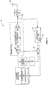
- FIG. 1 illustrates a system 10 that includes a transmitter 12 and an undersampled TOR 14 according to one embodiment of the present disclosure.
- the transmitter 12 includes a Digital Predistortion (DPD) subsystem 16, an upconversion and Digital-to-Analog (D/A) conversion subsystem 18, and a power amplifier (PA) 20 connected as shown.
- DPD Digital Predistortion
- D/A Digital-to-Analog
- PA power amplifier
- a baseband processor 22 provides a digital transmit signal to an input of the transmitter 12.
- the digital transmit signal is predistorted by the DPD subsystem 16 to provide a predistorted transmit signal.
- the DPD subsystem 16 is adaptively configured to compensate for a nonlinearity of the transmitter 12 and, in particular, a nonlinearity of the PA 20.
- the DPD subsystem 16 is configured such that Inter-Modulation Distortion (IMD) resulting from the nonlinearity of the transmitter 12 that falls within a desired transmit band (i.e., a pass-band of a transmit (TX) filter 24) is minimized or at least substantially reduced.
- IMD Inter-Modulation Distortion
- the predistorted transmit signal output by the DPD subsystem 16 is upconverted and digital-to-analog converted by the upconversion and D/A conversion subsystem 18.
- the upconversion and D/A conversion subsystem 18 may include additional gain and/or filtering stages.
- the output of the upconversion and D/A conversion subsystem 18 is then amplified by the PA 20 to provide a radio frequency transmit signal at an output of the transmitter 12.
- the radio frequency transmit signal is filtered by the TX filter 24 to remove undesired frequency components (e.g., undesired IMD) that fall outside of the desired transmit band.
- the filtered radio frequency transmit signal is then transmitted via an antenna 26.
- the system 10 includes a feedback path including the undersampled TOR 14 that is utilized to adaptively configure the DPD subsystem 16.
- a coupler 28 couples the output of the transmitter 12 to an input of the undersampled TOR 14.
- the undersampled TOR 14 downconverts the radio frequency transmit signal output by the transmitter 12 to a desired intermediate frequency and then, using an Analog-to-Digital Converter (ADC) 30, samples the downconverted signal at a desired undersampling rate to provide a digital TOR output signal.
- ADC Analog-to-Digital Converter
- undersampling rate is used herein to refer to a sampling rate that is less than the Nyquist sampling rate (i.e., the undersampling rate is a sampling rate that is less than 2 times a highest frequency of the sampled signal).
- the radio frequency transmit signal is downconverted to a desired intermediate frequency prior to analog-to-digital (A/D) conversion
- A/D analog-to-digital
- the digital TOR output signal is provided to a first input of a subtractor 32.
- An adjusted version of the digital transmit signal is provided to a second input of the subtractor 32.
- the adjusted version of the digital transmit signal is provided by passing the digital transmit signal through a channel estimate function 34 that is a model of a channel from the output of the transmitter 12 to the output of the undersampled TOR 14 and an undersampling (US) function 36 that has the same undersampling rate as the undersampled TOR 14.
- the subtractor 32 outputs an error signal that is equal to a difference between the adjusted version of the digital transmit signal and the digital TOR output signal.
- the DPD subsystem 16 is calibrated based on the error signal. In particular, the DPD subsystem 16 is adaptively configured to minimize, or at least substantially reduce, the error signal.
- the system 10 operates in a characterization mode in which one or more probe signals are transmitted via the transmitter 12 and received by the undersampled TOR 14.
- the transmitter 12 is a digital transmitter as disclosed in U.S. Patent Application Publication No. 2010/0098191 , entitled METHODS AND SYSTEMS FOR PROGRAMMABLE DIGITAL UP-CONVERSION, which published April 22, 2010. Note, however, that while in the embodiment of Figure 1 the probe signal(s) are provided internally via the transmitter 12, the present disclosure is not limited thereto.
- the probe signal(s) is(are) provided by an external device or system (e.g., an arbitrary waveform generator such as those manufactured and sold by Agilent) that is connected to the input of the undersampled TOR 14 during characterization.
- an external device or system e.g., an arbitrary waveform generator such as those manufactured and sold by Agilent
- Each of the one or more probe signals is such that all aliases in the corresponding digital TOR output signal in response to the probe signal are unique.
- an undersampled TOR characterization function 38 of the baseband processor 22 is enabled to "un-alias" the digital TOR output signal(s) output by the undersampled TOR 14 in response to the probe signal(s).
- the undersampled TOR characterization function 38 is enabled to characterize the undersampled TOR 14 across an entire input bandwidth of the undersampled TOR 14.
- characterizing the undersampled TOR 14 includes estimating a frequency response (e.g., amplitude and phase) of the undersampled TOR 14 across the entire input bandwidth of the undersampled TOR 14.
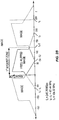
- FIGS 2A and 2B are frequency domain illustrations of an exemplary analog input signal to the ADC 30 of the undersampled TOR 14 and the resulting digital output signal output by the ADC 30 of the undersampled TOR 14. More specifically, as illustrated in Figure 2A , the analog input signal of the ADC 30 is centered at an intermediate frequency (f IF ) and spans a frequency range from a lower frequency (f L ) to a higher frequency (f H ). In this example, f IF is equal to 184.32 megahertz (MHz), f L is equal to 61.44 MHz, and f H is equal to 307.2 MHz. As such, the bandwidth of the analog input signal is 245.76 MHz.
- f IF intermediate frequency
- f L is equal to 184.32 megahertz
- f L is equal to 61.44 MHz
- f H is equal to 307.2 MHz.
- the bandwidth of the analog input signal is 245.76 MHz.
- an undersampling rate (f S ) of the ADC 30 is 245.76 Mega Samples per second (MSps).
- two of the images are located at -61.44 MHz and 184.32 MHz, as illustrated in Figure 2B .
- Figure 2B illustrates the frequency-flipped image of the analog input signal located at 61.44 MHz.
- the digital output signal of the ADC 30 is a digital representation of the signal in a first Nyquist zone of the ADC 30, where the first Nyquist zone is the frequency range of 0 to f S /2.
- the undersampled TOR 14 cannot be characterized using traditional characterization techniques.
- traditional characterization techniques are unable to un-alias the digital TOR output signal because, traditionally, at least some frequency components of the digital TOR output signal include contributions from different Nyquist zones.
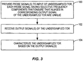
- FIG 3 illustrates a process for characterizing the undersampled TOR 14 of Figure 1 according to one embodiment of the present disclosure.
- one or more probe signals are provided to the input of the undersampled TOR 14 (step 100).
- Each probe signal of the one or more probe signals has selective frequency components that ensure that aliases in the corresponding digital TOR output signal are unique.
- each probe signal is an Orthogonal Frequency Division Multiplexing (OFDM) or OFDM-like signal having multiple carrier frequencies or multiple frequency tones.
- OFDM Orthogonal Frequency Division Multiplexing
- the probe signals are not limited thereto and may alternatively be time domain signals designed to have multiple separate and distinct frequency components.
- each selective frequency component may or may not be modulated.
- each subcarrier or frequency tone may be modulated using a Quadrature Phase Shift Keying (QPSK) modulation scheme.
- QPSK Quadrature Phase Shift Keying
- the frequency components of the one or more probe signals are selected such that all aliases of the frequency components of the probe signal are at unique frequencies. In other words, the frequency components of the probe signal are selected such that no two aliases are at the same frequency.
- a single probe signal is provided to the input of the undersampled TOR 14, where the single probe signal has selective frequency components that span the entire input bandwidth of the undersampled TOR 14 and ensure that aliases in the digital TOR output signal are unique.
- multiple probe signals are successively provided to the input of the undersampled TOR 14 where each of the probe signals has selective frequency components that span a different portion of the input bandwidth of the undersampled TOR 14 and ensure that aliases in the digital TOR output signal are unique.
- the transmitter 12 is a digital transmitter such as, for example, the digital transmitter disclosed in U.S. Patent Application Publication No. 2010/0098191 , and the transmitter 12 generates the one or more probe signals.
- the transmitter 12 due to the digital nature of the signal synthesis of the one or more probe signals and the undersampled TOR output signal, spacing of selective frequency components of the one or more probe signals is essentially arbitrary. As such, any desired resolution can be achieved. Note, however, that the selective frequency components of each probe signal are still selected such that all aliases in the corresponding output signal of the undersampled TOR 14 in response to the probe signal are unique.
- One or more digital TOR output signals are received from the output of the undersampled TOR 14 in response to the one or more probe signals (step 102).
- the undersampled TOR 14 is then characterized based on the one or more digital TOR output signals (step 104).
- the undersampled TOR 14 can be characterized by comparing the one or more digital TOR output signals with the one or more probe signals. More specifically, for each probe signal, all aliases in the corresponding digital TOR output signal are unique. As such, each digital TOR output signal can be un-aliased such that the contribution of each frequency component of the corresponding probe signal in the digital TOR output signal can be determined.
- the one or more digital TOR output signals can be compared to the corresponding one or more probe signals to characterize the undersampled TOR 14.
- characterization of the undersampled TOR 14 includes determining a frequency response of the undersampled TOR 14 across the entire input bandwidth of the undersampled TOR 14.
- Figure 4 illustrates a process for characterizing the undersampled TOR 14 of Figure 1 according to another embodiment of the present disclosure.
- This embodiment is similar to that of Figure 3 but where a single probe signal having selective frequency components that span the entire input bandwidth of the undersampled TOR 14 is utilized for characterization. More specifically, first, a probe signal is provided to the input of the undersampled TOR 14 (step 200).
- the probe signal has selective frequency components that span the entire input bandwidth of the undersampled TOR 14 and ensure that aliases in the digital TOR output signal are unique.
- the probe signal is an OFDM or OFDM-like signal having multiple carrier frequencies or multiple frequency tones that are selected such that aliases in the digital TOR output signal are unique.
- the probe signal is not limited thereto and may alternatively be time domain signal designed to have multiple separate and distinct frequency components that are selected such that aliases in the digital TOR output signal are unique.
- each selective frequency component may or may not be modulated.
- each subcarrier or frequency tone may be modulated using a QPSK modulation scheme.
- a digital TOR output signal is received from the output of the undersampled TOR 14 in response to the probe signal (step 202).
- the undersampled TOR 14 is then characterized based on the digital TOR output signal (step 204). More specifically, since the aliases in the digital TOR output signal are unique, the digital TOR output signal can be un-aliased such that the contribution of each frequency component of the probe signal in the digital TOR output signal can be determined.
- characterization of the undersampled TOR 14 includes determining a frequency response of the undersampled TOR 14 across the entire input bandwidth of the undersampled TOR 14.
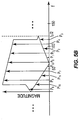
- Figures 5A and 5B graphically illustrate one example of the selection of the frequency components of the probe signal of Figure 4 such that aliases in the digital TOR output signal are unique. More specifically, Figure 5A is a frequency domain illustration of the probe signal after downconversion to a desired intermediate frequency. The resulting intermediate frequency probe signal illustrated in Figure 5A is provided to the input of the ADC 30 of the undersampled TOR 14. As illustrated, the intermediate frequency probe signal includes selective frequency components indicated as P 1 through P 12 that span the entire input bandwidth of the undersampled TOR 14. Note that while only twelve selective frequency components are illustrated in this example for clarity and ease of discussion, the probe signal, and thus the intermediate frequency probe signal, may have many more frequency components (e.g., 127 or more frequency components). As illustrated in Figure 5B , the selective frequency components P 1 through P 12 are selected such that aliases of the selective frequency components P 1 through P 12 are unique in the digital TOR output signal.
- the selective frequency components P 1 through P 12 are selected such that aliases of the selective frequency components P 1 through
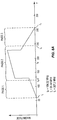
- Figures 6A and 6B illustrate another example of the selection of the frequency components of the probe signal of Figure 4 such that aliases in the digital TOR output signal are unique. More specifically, Figure 6A is a frequency domain illustration of the probe signal after downconversion to a desired intermediate frequency. Notably, in this example, the input bandwidth of the undersampled TOR 14, and thus the frequency span of the probe signal, is wider than in the previous example. Specifically, in this example, the input bandwidth of the undersampled TOR 14 is 350 MHz. Using the same undersampling rate, up to three aliases can be located at the same frequency in the digital TOR output signal. In other words, without careful selection of the frequency components in the probe signal, aliases in the digital TOR output signal can be non-unique.
- the probe signal includes 127 selective frequency components that span the entire input bandwidth of the undersampled TOR 14, which are indicated by corresponding dots in the illustration of the probe signal after downconversion to the desired intermediate frequency shown in Figure 6A .
- the selective frequency components of the probe signal are selected such that aliases of the selective frequency components are unique in the digital TOR output signal.
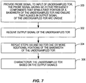
- Figure 7 illustrates a process for characterizing the undersampled TOR 14 of Figure 1 according to another embodiment of the present disclosure.
- This embodiment is similar to that of Figure 3 but where multiple successive probe signals having selective frequency components that span different portions of the input bandwidth of the undersampled TOR 14 are utilized for characterization.
- This embodiment is referred to herein as a multi-pass embodiment.
- the input bandwidth of the undersampled TOR 14 spans multiple ADC Nyquist zones, and the probe signals include frequency components in different Nyquist zones.
- the number of probe signals is equal to the number of Nyquist zones spanned by the input bandwidth of the undersampled TOR 14.
- the number of probe signals may be less than the number of Nyquist zones spanned by the input bandwidth of the undersampled TOR 14.
- two probe signals may be used for an embodiment where the input bandwidth spans three Nyquist zones.
- the frequency components of the probe signal are selected such that all aliases in the corresponding digital TOR output signal are unique.
- a probe signal that includes selective frequency components that spans a first portion of the bandwidth of receive band of the undersampled TOR 14 is provided to the input of the undersampled TOR 14 (step 300).
- the first portion of the bandwidth of the receive band of the undersampled TOR 14 is a portion of the bandwidth of the receive band of the undersampled TOR 14 in one Nyquist zone.
- the selective frequency components of the probe signal ensure that aliases in the digital TOR output signal in response to the probe signal are unique.
- the first portion of the bandwidth of the receive band may span more than one Nyquist zone.
- the probe signal is an OFDM or OFDM-like signal having multiple carrier frequencies or multiple frequency tones in the first portion of the bandwidth of the receive band of the undersampled TOR 14.
- the probe signal is not limited thereto and may alternatively be a time domain signal designed to have multiple separate and distinct frequency components in the first portion of the bandwidth of the receive band of the undersampled TOR 14.
- each selective frequency component may or may not be modulated.
- each subcarrier or frequency tone may be modulated using a QPSK modulation scheme.
- a digital TOR output signal is received from the output of the undersampled TOR 14 in response to the probe signal (step 302).
- Steps 300 and 302 are then repeated for one or more additional probe signals that have selective frequency components for one or more different portions of the bandwidth of the receive band of the undersampled TOR 14 (step 304).
- the undersampled TOR 14 is then characterized based on the digital TOR output signals received in response to the probe signals (step 306). More specifically, for each probe signal, all aliases in the corresponding digital TOR output signal are unique. As such, each of the digital TOR output signals can be un-aliased such that the contribution of each frequency component of the corresponding probe signal in the digital TOR output signal can be determined.
- characterization of the undersampled TOR 14 includes determining a frequency response of the undersampled TOR 14 across the entire input bandwidth of the undersampled TOR 14.
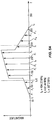
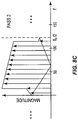
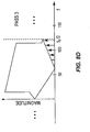
- FIGS 8A through 8D graphically illustrate one example of the probe signals of Figure 7 . More specifically, as illustrated in Figure 8A , a bandwidth of the undersampled TOR 14 after downconversion to the desired intermediate frequency (f IF ) spans from a lower frequency (f L ) to a higher frequency (f H ). Further, the bandwidth of the undersampled TOR 14 spans three Nyquist zones, namely, a first Nyquist zone from 0 to f 2 /2, a second Nyquist zone from f S /2 to f S , and a third Nyquist zone from f S to 3f S /2.
- a probe signal for a first pass includes selective frequency components that span a frequency range from f L to f S /2
- a probe signal for a second pass includes selective frequency components that span a frequency range from f S /2 to f S
- a probe signal for a third pass includes selective frequency components that span a frequency range from f S to f H .
- the digital TOR output signal received in response to the probe signal for the first pass includes unique aliases, as illustrated in Figure 8B .
- the selective frequency components for the probe signal for the first pass only span the frequency range of f L to f S /2 and, as such, the probe signal does not include any selective frequency components in the other portions of the bandwidth of the undersampled TOR 14 that would have aliases that would collide with the aliases of the selective frequency components of the probe signal in the digital TOR output signal.
- the corresponding digital TOR output signals received in response to the probe signals for the second and third passes include unique aliases, as illustrated in Figures 8C and 8D .
- One advantage of the systems and methods disclosed herein is to allow characterization of an undersampled receiver even though the receiver itself results in a large amount of aliasing.
- the undersampled receiver is a very useful concept in wideband applications as it enables using a much lower sample rate to observe a wideband signal and consequently allows a much lower computational rate to determine DPD parameters.
Landscapes
- Engineering & Computer Science (AREA)
- Power Engineering (AREA)
- Computer Networks & Wireless Communication (AREA)
- Signal Processing (AREA)
- Physics & Mathematics (AREA)
- Nonlinear Science (AREA)
- Magnetic Resonance Imaging Apparatus (AREA)
- Superheterodyne Receivers (AREA)
Claims (13)
- Procédé de caractérisation d'un récepteur sous-échantillonné, comprenant :la fourniture successive (100) de multiples signaux de sonde à une entrée du récepteur sous-échantillonné,dans lequel chaque signal de sonde des multiples signaux de sonde a des composantes fréquentielles sélectives dans une partie différente d'une bande de réception du récepteur sous-échantillonné ; etdans lequel chaque signal de sonde des multiples signaux de sonde a des composantes fréquentielles sélectives qui assurent que des composantes de repliement dans un signal correspondant des multiples signaux de sortie du récepteur sous-échantillonné sont uniques de sorte que les composantes fréquentielles des multiples signaux de sonde sont sélectionnées de sorte deux composantes de repliement ne sont pas à la même fréquence ; etla détermination (104) d'une réponse en fréquence du récepteur sous-échantillonné dans toute la largeur de bande d'entrée du récepteur sous-échantillonné sur la base des multiples signaux de sortie sortis successivement par le récepteur sous-échantillonné en réponse aux multiples signaux de sonde.
- Procédé selon la revendication 1, dans lequel chaque signal de sonde des multiples signaux de sonde est un signal à multiples sous-porteuses ayant des sous-porteuses sélectives qui sont sélectionnées parmi un ensemble de toutes les sous-porteuses possibles du signal à multiples sous-porteuses de sorte que des composantes de repliement dans le signal correspondant des multiples signaux de sortie du récepteur sous-échantillonné sont uniques.
- Procédé selon la revendication 2, dans lequel les sous-porteuses sélectives du signal à multiples sous-porteuses sont modulées.
- Procédé selon la revendication 1, dans lequel chaque signal de sonde des multiples signaux de sonde est un signal à multiples tonalités ayant des tonalités sélectives qui sont sélectionnées parmi un ensemble de toutes les tonalités possibles du signal à multiples tonalités de sorte que des composantes de repliement dans le signal correspondant des multiples signaux de sortie du récepteur sous-échantillonné sont uniques.
- Procédé selon la revendication 4 dans lequel les tonalités sélectives du signal à multiples tonalités sont modulées.
- Procédé selon l'une quelconque des revendications précédentes, dans lequel pour une largeur de bande d'une bande de réception du récepteur sous-échantillonné pour lequel une caractérisation est souhaitée, une largeur de bande correspondante en une entrée d'un convertisseur analogique-numérique du récepteur sous-échantillonné couvre de multiples zones de Nyquist du convertisseur analogique-numérique.
- Procédé selon la revendication 1 dans lequel :- les parties différentes de la bande de réception du récepteur sous-échantillonné, dans lequel les multiples signaux de sonde ont des composantes fréquentielles sélectives, correspondent à différentes zones de Nyquist d'un convertisseur analogique-numérique du récepteur sous-échantillonné ; ou- chaque signal de sonde des multiples signaux de sonde est un signal à multiples sous-porteuses ayant des sous-porteuses sélectives qui sont sélectionnées parmi un ensemble de toutes les sous-porteuses possibles du signal à multiples sous-porteuses de sorte que des composantes de repliement dans un signal correspondant des multiples signaux de sortie du récepteur sous-échantillonné sont uniques ; ou- chaque signal de sonde des multiples signaux de sonde est un signal à multiples tonalités ayant des tonalités sélectives qui sont sélectionnées parmi un ensemble de toutes les tonalités possibles du signal à multiples tonalités de sorte que des composantes de repliement dans un signal correspondant des multiples signaux de sortie du récepteur sous-échantillonné sont uniques.
- Procédé selon l'une quelconque des revendications précédentes, dans lequel le récepteur sous-échantillonné et un émetteur (12) sont incorporés dans un dispositif de communication (10), et la fourniture des un ou plusieurs signaux de sonde à l'entrée du récepteur sous-échantillonné comprend :la génération des multiples signaux de sonde via l'émetteur ; etla fourniture des un ou plusieurs signaux de sonde à l'entrée du récepteur sous-échantillonné via un coupleur qui couple une sortie de l'émetteur à l'entrée du récepteur sous-échantillonné.
- Procédé selon l'une quelconque des revendications précédentes, dans lequel :- la fourniture de multiples signaux de sonde à l'entrée du récepteur sous-échantillonné comprend la fourniture des multiples signaux de sonde d'un dispositif externe de génération de signaux à l'entrée du récepteur sous-échantillonné ; et/ou- la caractérisation du récepteur sous-échantillonné comprend une non-distorsion de repliement des multiples signaux de sortie.
- Procédé selon l'une quelconque des revendications précédentes, dans lequel le récepteur sous-échantillonné est un récepteur d'observation d'émission sous-échantillonné couplé à une sortie d'un émetteur (12), et la caractérisation du récepteur sous-échantillonné comprend la génération d'un modèle d'un canal entre la sortie de l'émetteur et une sortie du récepteur d'observation d'émission sous-échantillonné.
- Procédé selon la revendication 10, comprenant en outre, durant le fonctionnement de l'émetteur :l'application du modèle à un signal d'entrée de l'émetteur pour fournir un signal de référence ;le sous-échantillonnage du signal de référence pour fournir un signal de référence sous-échantillonné ; etla configuration adaptative d'une prédistorsion numérique dans l'émetteur sur la base d'une différence entre le signal de référence sous-échantillonné et la sortie du récepteur d'observation d'émission sous-échantillonné.
- Système (10) comprenant :un récepteur sous-échantillonné (14) ;un moyen configuré pour générer de multiples signaux de sonde et pour fournir successivement les multiples signaux de sonde à une entrée du récepteur sous-échantillonné,dans lequel chaque signal de sonde des multiples signaux de sonde a des composantes fréquentielles sélectives dans une partie différente d'une bande de réception du récepteur sous-échantillonné ; etdans lequel chaque signal de sonde des multiples signaux de sonde a des composantes fréquentielles sélectives qui assurent que des composantes de repliement dans un signal correspondant des multiples signaux de sortie du récepteur sous-échantillonné sont uniques de sorte que les composantes fréquentielles des multiples signaux de sonde sont sélectionnées de sorte que deux composantes de repliement ne sont pas à la même fréquence ; etun moyen configuré pour déterminer une réponse en fréquence du récepteur sous-échantillonné dans toute la largeur de bande d'entrée du récepteur sous-échantillonné sur la base des multiples signaux de sortie sortis successivement par le récepteur sous-échantillonné en réponse aux multiples signaux de sonde.
- Système selon la revendication 12, dans lequel :- les parties différentes de la bande de réception du récepteur sous-échantillonné dans lequel les multiples signaux de sonde ont des composantes fréquentielles sélectives correspondent à différentes zones de Nyquist d'un convertisseur analogique-numérique du récepteur sous-échantillonné ; ou- chaque signal de sonde des multiples signaux de sonde est un signal à multiples sous-porteuses ayant des sous-porteuses sélectives qui sont sélectionnées parmi un ensemble de toutes les sous-porteuses possibles du signal à multiples sous-porteuses de sorte que des composantes de repliement dans le signal correspondant des multiples signaux de sortie du récepteur sous-échantillonné sont uniques ; ou- chaque signal de sonde des multiples signaux de sonde est un signal à multiples tonalités ayant des tonalités sélectives qui sont sélectionnées parmi un ensemble de toutes les tonalités possibles du signal à multiples tonalités de sorte que des composantes de repliement dans le signal correspondant des multiples signaux de sortie du récepteur sous-échantillonné sont uniques.
Applications Claiming Priority (1)
| Application Number | Priority Date | Filing Date | Title |
|---|---|---|---|
| US13/754,263 US9497061B2 (en) | 2013-01-30 | 2013-01-30 | Undersampled receiver characterization |
Publications (3)
| Publication Number | Publication Date |
|---|---|
| EP2763368A2 EP2763368A2 (fr) | 2014-08-06 |
| EP2763368A3 EP2763368A3 (fr) | 2016-05-11 |
| EP2763368B1 true EP2763368B1 (fr) | 2018-04-25 |
Family
ID=50002469
Family Applications (1)
| Application Number | Title | Priority Date | Filing Date |
|---|---|---|---|
| EP14000237.9A Active EP2763368B1 (fr) | 2013-01-30 | 2014-01-23 | Caractérisation de récepteur sous-échantillonné |
Country Status (2)
| Country | Link |
|---|---|
| US (1) | US9497061B2 (fr) |
| EP (1) | EP2763368B1 (fr) |
Families Citing this family (5)
| Publication number | Priority date | Publication date | Assignee | Title |
|---|---|---|---|---|
| US9735741B2 (en) * | 2014-08-28 | 2017-08-15 | Analog Devices Global | Receivers for digital predistortion |
| US10681558B2 (en) * | 2016-06-23 | 2020-06-09 | Apple Inc. | Methods and devices for user detection in spectrum sharing |
| US10361898B2 (en) * | 2016-08-20 | 2019-07-23 | Huawei Technologies Co., Ltd. | Complexity reduction for OFDM signal transmissions |
| EP3782405A1 (fr) * | 2018-04-20 | 2021-02-24 | Telefonaktiebolaget Lm Ericsson (Publ) | Procédé et appareil d'émission et de réception efficaces d'énergie d'un signal utilisant une distorsion de repliement |
| EP4425791B1 (fr) | 2023-03-01 | 2025-12-10 | Nokia Solutions and Networks Oy | Système et procédé de compression de rétroaction par combinaison d'échantillons en prédistorsion numérique |
Family Cites Families (9)
| Publication number | Priority date | Publication date | Assignee | Title |
|---|---|---|---|---|
| US6342810B1 (en) * | 1999-07-13 | 2002-01-29 | Pmc-Sierra, Inc. | Predistortion amplifier system with separately controllable amplifiers |
| US7236532B2 (en) | 2001-06-11 | 2007-06-26 | Texas Instruments Incorporated | Method of initializing a communication system with different bandwidth receivers and transmitters |
| US6985704B2 (en) * | 2002-05-01 | 2006-01-10 | Dali Yang | System and method for digital memorized predistortion for wireless communication |
| US20050242876A1 (en) | 2004-04-28 | 2005-11-03 | Obernosterer Frank G E | Parameter estimation method and apparatus |
| ATE487272T1 (de) | 2004-05-19 | 2010-11-15 | Ericsson Telefon Ab L M | Adaptives vorverzerrungsverfahren und anordnung |
| JP4459029B2 (ja) * | 2004-11-22 | 2010-04-28 | 富士通株式会社 | Ofdm無線受信機 |
| US8553807B2 (en) | 2008-10-20 | 2013-10-08 | Apple Inc. | Methods and systems for programmable digital up-conversion |
| US8670501B2 (en) | 2009-12-09 | 2014-03-11 | Texas Instruments Incorporated | Digital pre-distortion of non-linear systems with reduced bandwidth feedback |
| US8351877B2 (en) | 2010-12-21 | 2013-01-08 | Dali Systems Co. Ltfd. | Multi-band wideband power amplifier digital predistorition system and method |
-
2013
- 2013-01-30 US US13/754,263 patent/US9497061B2/en not_active Expired - Fee Related
-
2014
- 2014-01-23 EP EP14000237.9A patent/EP2763368B1/fr active Active
Non-Patent Citations (1)
| Title |
|---|
| None * |
Also Published As
| Publication number | Publication date |
|---|---|
| US20140213206A1 (en) | 2014-07-31 |
| EP2763368A3 (fr) | 2016-05-11 |
| EP2763368A2 (fr) | 2014-08-06 |
| US9497061B2 (en) | 2016-11-15 |
Similar Documents
| Publication | Publication Date | Title |
|---|---|---|
| EP2404418B1 (fr) | Préfiltre compensateur pour émetteur OFDM | |
| EP2991221B1 (fr) | Récepteurs de prédistorsion numérique | |
| Anttila et al. | Frequency-selective I/Q mismatch calibration of wideband direct-conversion transmitters | |
| US6934341B2 (en) | Method and apparatus for plurality signal generation | |
| US7539268B2 (en) | Transmission/reception arrangement and method for reducing nonlinearities in output signals from a transmission/reception arrangement | |
| EP2763368B1 (fr) | Caractérisation de récepteur sous-échantillonné | |
| CA2714786A1 (fr) | Systeme et methode de linearisation d'amplificateur multi-porteur | |
| EP1949635A2 (fr) | Diminution de la puissance de la valeur crete a la valeur moyenne | |
| CA2724735A1 (fr) | Systeme et procede pour une estimation de desequilibre serie avec quadrature en utilisant une boucle de retour avec un decalage en frequence | |
| KR101476693B1 (ko) | 비-이상적 트랜시버에 대한 캘리브레이션 방법 | |
| US8224268B2 (en) | Transmitter linearization | |
| CN103119871B (zh) | 确定不同信号分支之间的频率相关不均衡的方法及装置 | |
| US6724331B1 (en) | Adaptive digital spectral compensation and calibration of analog components and transceiver chains | |
| KR101980862B1 (ko) | 트랜시버 내 국부 발진기의 위상 동기화를 위한 장치 및 방법 | |
| US20080317165A1 (en) | Systems and methods of calibrating a transmitter | |
| JP2008172838A (ja) | 無線送信機 | |
| Sun et al. | Optimal pilot based frequency-dependent I/Q imbalance compensation for wideband direct-conversion transmitters | |
| WO2007134637A1 (fr) | Appareil pour surveiller les distorsions non linéaires de signaux radio et procédé connexe | |
| KR20140124178A (ko) | 포락선 검출기를 포함하는 mimo 송신시스템 및 mimo 송신시스템을 구성하는 전치왜곡기의 설계방법 | |
| CN101436876A (zh) | 一种对消测试信号的方法和系统 | |
| JPWO2015114702A1 (ja) | 送信装置及びその制御方法 | |
| US20240187025A1 (en) | Feedforward distortion cancellation apparatus and method | |
| US8989250B1 (en) | Method and apparatus for equalizing distortion in a digital pre-distortion observation path | |
| JP2006304191A (ja) | マルチキャリア送信装置及び周波数偏差校正方法 | |
| EP3716491B1 (fr) | Annulation de composant de signal pour récepteur de rétroaction |
Legal Events
| Date | Code | Title | Description |
|---|---|---|---|
| PUAI | Public reference made under article 153(3) epc to a published international application that has entered the european phase |
Free format text: ORIGINAL CODE: 0009012 |
|
| 17P | Request for examination filed |
Effective date: 20140123 |
|
| AK | Designated contracting states |
Kind code of ref document: A2 Designated state(s): AL AT BE BG CH CY CZ DE DK EE ES FI FR GB GR HR HU IE IS IT LI LT LU LV MC MK MT NL NO PL PT RO RS SE SI SK SM TR |
|
| AX | Request for extension of the european patent |
Extension state: BA ME |
|
| PUAL | Search report despatched |
Free format text: ORIGINAL CODE: 0009013 |
|
| AK | Designated contracting states |
Kind code of ref document: A3 Designated state(s): AL AT BE BG CH CY CZ DE DK EE ES FI FR GB GR HR HU IE IS IT LI LT LU LV MC MK MT NL NO PL PT RO RS SE SI SK SM TR |
|
| AX | Request for extension of the european patent |
Extension state: BA ME |
|
| R17P | Request for examination filed (corrected) |
Effective date: 20160810 |
|
| RBV | Designated contracting states (corrected) |
Designated state(s): AL AT BE BG CH CY CZ DE DK EE ES FI FR GB GR HR HU IE IS IT LI LT LU LV MC MK MT NL NO PL PT RO RS SE SI SK SM TR |
|
| STAA | Information on the status of an ep patent application or granted ep patent |
Free format text: STATUS: EXAMINATION IS IN PROGRESS |
|
| 17Q | First examination report despatched |
Effective date: 20161122 |
|
| GRAP | Despatch of communication of intention to grant a patent |
Free format text: ORIGINAL CODE: EPIDOSNIGR1 |
|
| STAA | Information on the status of an ep patent application or granted ep patent |
Free format text: STATUS: GRANT OF PATENT IS INTENDED |
|
| RIC1 | Information provided on ipc code assigned before grant |
Ipc: H04L 27/26 20060101ALI20180102BHEP Ipc: H04L 27/36 20060101AFI20180102BHEP Ipc: H03F 1/32 20060101ALI20180102BHEP Ipc: H04L 5/00 20060101ALI20180102BHEP Ipc: H04L 25/02 20060101ALI20180102BHEP Ipc: H03F 3/24 20060101ALI20180102BHEP Ipc: H04B 17/20 20150101ALI20180102BHEP |
|
| INTG | Intention to grant announced |
Effective date: 20180130 |
|
| GRAS | Grant fee paid |
Free format text: ORIGINAL CODE: EPIDOSNIGR3 |
|
| GRAA | (expected) grant |
Free format text: ORIGINAL CODE: 0009210 |
|
| STAA | Information on the status of an ep patent application or granted ep patent |
Free format text: STATUS: THE PATENT HAS BEEN GRANTED |
|
| AK | Designated contracting states |
Kind code of ref document: B1 Designated state(s): AL AT BE BG CH CY CZ DE DK EE ES FI FR GB GR HR HU IE IS IT LI LT LU LV MC MK MT NL NO PL PT RO RS SE SI SK SM TR |
|
| REG | Reference to a national code |
Ref country code: GB Ref legal event code: FG4D |
|
| REG | Reference to a national code |
Ref country code: CH Ref legal event code: EP |
|
| REG | Reference to a national code |
Ref country code: AT Ref legal event code: REF Ref document number: 994026 Country of ref document: AT Kind code of ref document: T Effective date: 20180515 |
|
| REG | Reference to a national code |
Ref country code: IE Ref legal event code: FG4D |
|
| REG | Reference to a national code |
Ref country code: DE Ref legal event code: R096 Ref document number: 602014024286 Country of ref document: DE |
|
| REG | Reference to a national code |
Ref country code: NL Ref legal event code: MP Effective date: 20180425 |
|
| REG | Reference to a national code |
Ref country code: LT Ref legal event code: MG4D |
|
| PG25 | Lapsed in a contracting state [announced via postgrant information from national office to epo] |
Ref country code: NL Free format text: LAPSE BECAUSE OF FAILURE TO SUBMIT A TRANSLATION OF THE DESCRIPTION OR TO PAY THE FEE WITHIN THE PRESCRIBED TIME-LIMIT Effective date: 20180425 |
|
| PG25 | Lapsed in a contracting state [announced via postgrant information from national office to epo] |
Ref country code: PL Free format text: LAPSE BECAUSE OF FAILURE TO SUBMIT A TRANSLATION OF THE DESCRIPTION OR TO PAY THE FEE WITHIN THE PRESCRIBED TIME-LIMIT Effective date: 20180425 Ref country code: LT Free format text: LAPSE BECAUSE OF FAILURE TO SUBMIT A TRANSLATION OF THE DESCRIPTION OR TO PAY THE FEE WITHIN THE PRESCRIBED TIME-LIMIT Effective date: 20180425 Ref country code: ES Free format text: LAPSE BECAUSE OF FAILURE TO SUBMIT A TRANSLATION OF THE DESCRIPTION OR TO PAY THE FEE WITHIN THE PRESCRIBED TIME-LIMIT Effective date: 20180425 Ref country code: BG Free format text: LAPSE BECAUSE OF FAILURE TO SUBMIT A TRANSLATION OF THE DESCRIPTION OR TO PAY THE FEE WITHIN THE PRESCRIBED TIME-LIMIT Effective date: 20180725 Ref country code: FI Free format text: LAPSE BECAUSE OF FAILURE TO SUBMIT A TRANSLATION OF THE DESCRIPTION OR TO PAY THE FEE WITHIN THE PRESCRIBED TIME-LIMIT Effective date: 20180425 Ref country code: SE Free format text: LAPSE BECAUSE OF FAILURE TO SUBMIT A TRANSLATION OF THE DESCRIPTION OR TO PAY THE FEE WITHIN THE PRESCRIBED TIME-LIMIT Effective date: 20180425 Ref country code: NO Free format text: LAPSE BECAUSE OF FAILURE TO SUBMIT A TRANSLATION OF THE DESCRIPTION OR TO PAY THE FEE WITHIN THE PRESCRIBED TIME-LIMIT Effective date: 20180725 |
|
| PG25 | Lapsed in a contracting state [announced via postgrant information from national office to epo] |
Ref country code: GR Free format text: LAPSE BECAUSE OF FAILURE TO SUBMIT A TRANSLATION OF THE DESCRIPTION OR TO PAY THE FEE WITHIN THE PRESCRIBED TIME-LIMIT Effective date: 20180726 Ref country code: LV Free format text: LAPSE BECAUSE OF FAILURE TO SUBMIT A TRANSLATION OF THE DESCRIPTION OR TO PAY THE FEE WITHIN THE PRESCRIBED TIME-LIMIT Effective date: 20180425 Ref country code: HR Free format text: LAPSE BECAUSE OF FAILURE TO SUBMIT A TRANSLATION OF THE DESCRIPTION OR TO PAY THE FEE WITHIN THE PRESCRIBED TIME-LIMIT Effective date: 20180425 Ref country code: RS Free format text: LAPSE BECAUSE OF FAILURE TO SUBMIT A TRANSLATION OF THE DESCRIPTION OR TO PAY THE FEE WITHIN THE PRESCRIBED TIME-LIMIT Effective date: 20180425 |
|
| REG | Reference to a national code |
Ref country code: AT Ref legal event code: MK05 Ref document number: 994026 Country of ref document: AT Kind code of ref document: T Effective date: 20180425 |
|
| PG25 | Lapsed in a contracting state [announced via postgrant information from national office to epo] |
Ref country code: PT Free format text: LAPSE BECAUSE OF FAILURE TO SUBMIT A TRANSLATION OF THE DESCRIPTION OR TO PAY THE FEE WITHIN THE PRESCRIBED TIME-LIMIT Effective date: 20180827 |
|
| REG | Reference to a national code |
Ref country code: DE Ref legal event code: R097 Ref document number: 602014024286 Country of ref document: DE |
|
| PG25 | Lapsed in a contracting state [announced via postgrant information from national office to epo] |
Ref country code: CZ Free format text: LAPSE BECAUSE OF FAILURE TO SUBMIT A TRANSLATION OF THE DESCRIPTION OR TO PAY THE FEE WITHIN THE PRESCRIBED TIME-LIMIT Effective date: 20180425 Ref country code: SK Free format text: LAPSE BECAUSE OF FAILURE TO SUBMIT A TRANSLATION OF THE DESCRIPTION OR TO PAY THE FEE WITHIN THE PRESCRIBED TIME-LIMIT Effective date: 20180425 Ref country code: RO Free format text: LAPSE BECAUSE OF FAILURE TO SUBMIT A TRANSLATION OF THE DESCRIPTION OR TO PAY THE FEE WITHIN THE PRESCRIBED TIME-LIMIT Effective date: 20180425 Ref country code: DK Free format text: LAPSE BECAUSE OF FAILURE TO SUBMIT A TRANSLATION OF THE DESCRIPTION OR TO PAY THE FEE WITHIN THE PRESCRIBED TIME-LIMIT Effective date: 20180425 Ref country code: AT Free format text: LAPSE BECAUSE OF FAILURE TO SUBMIT A TRANSLATION OF THE DESCRIPTION OR TO PAY THE FEE WITHIN THE PRESCRIBED TIME-LIMIT Effective date: 20180425 Ref country code: EE Free format text: LAPSE BECAUSE OF FAILURE TO SUBMIT A TRANSLATION OF THE DESCRIPTION OR TO PAY THE FEE WITHIN THE PRESCRIBED TIME-LIMIT Effective date: 20180425 |
|
| REG | Reference to a national code |
Ref country code: CH Ref legal event code: PK Free format text: BERICHTIGUNGEN |
|
| RIC2 | Information provided on ipc code assigned after grant |
Ipc: H04L 5/00 20060101ALI20180102BHEP Ipc: H04L 27/26 20060101ALI20180102BHEP Ipc: H04B 17/20 20150101ALI20180102BHEP Ipc: H03F 3/24 20060101ALI20180102BHEP Ipc: H04L 25/02 20060101ALI20180102BHEP Ipc: H03F 1/32 20060101ALI20180102BHEP Ipc: H04L 27/36 20060101AFI20180102BHEP |
|
| PG25 | Lapsed in a contracting state [announced via postgrant information from national office to epo] |
Ref country code: IT Free format text: LAPSE BECAUSE OF FAILURE TO SUBMIT A TRANSLATION OF THE DESCRIPTION OR TO PAY THE FEE WITHIN THE PRESCRIBED TIME-LIMIT Effective date: 20180425 Ref country code: SM Free format text: LAPSE BECAUSE OF FAILURE TO SUBMIT A TRANSLATION OF THE DESCRIPTION OR TO PAY THE FEE WITHIN THE PRESCRIBED TIME-LIMIT Effective date: 20180425 |
|
| PLBE | No opposition filed within time limit |
Free format text: ORIGINAL CODE: 0009261 |
|
| STAA | Information on the status of an ep patent application or granted ep patent |
Free format text: STATUS: NO OPPOSITION FILED WITHIN TIME LIMIT |
|
| 26N | No opposition filed |
Effective date: 20190128 |
|
| PG25 | Lapsed in a contracting state [announced via postgrant information from national office to epo] |
Ref country code: SI Free format text: LAPSE BECAUSE OF FAILURE TO SUBMIT A TRANSLATION OF THE DESCRIPTION OR TO PAY THE FEE WITHIN THE PRESCRIBED TIME-LIMIT Effective date: 20180425 |
|
| PG25 | Lapsed in a contracting state [announced via postgrant information from national office to epo] |
Ref country code: MC Free format text: LAPSE BECAUSE OF FAILURE TO SUBMIT A TRANSLATION OF THE DESCRIPTION OR TO PAY THE FEE WITHIN THE PRESCRIBED TIME-LIMIT Effective date: 20180425 |
|
| REG | Reference to a national code |
Ref country code: CH Ref legal event code: PL |
|
| PG25 | Lapsed in a contracting state [announced via postgrant information from national office to epo] |
Ref country code: LU Free format text: LAPSE BECAUSE OF NON-PAYMENT OF DUE FEES Effective date: 20190123 |
|
| REG | Reference to a national code |
Ref country code: BE Ref legal event code: MM Effective date: 20190131 |
|
| REG | Reference to a national code |
Ref country code: IE Ref legal event code: MM4A |
|
| PG25 | Lapsed in a contracting state [announced via postgrant information from national office to epo] |
Ref country code: BE Free format text: LAPSE BECAUSE OF NON-PAYMENT OF DUE FEES Effective date: 20190131 Ref country code: AL Free format text: LAPSE BECAUSE OF FAILURE TO SUBMIT A TRANSLATION OF THE DESCRIPTION OR TO PAY THE FEE WITHIN THE PRESCRIBED TIME-LIMIT Effective date: 20180425 |
|
| PG25 | Lapsed in a contracting state [announced via postgrant information from national office to epo] |
Ref country code: CH Free format text: LAPSE BECAUSE OF NON-PAYMENT OF DUE FEES Effective date: 20190131 Ref country code: LI Free format text: LAPSE BECAUSE OF NON-PAYMENT OF DUE FEES Effective date: 20190131 |
|
| PG25 | Lapsed in a contracting state [announced via postgrant information from national office to epo] |
Ref country code: IE Free format text: LAPSE BECAUSE OF NON-PAYMENT OF DUE FEES Effective date: 20190123 |
|
| PG25 | Lapsed in a contracting state [announced via postgrant information from national office to epo] |
Ref country code: TR Free format text: LAPSE BECAUSE OF FAILURE TO SUBMIT A TRANSLATION OF THE DESCRIPTION OR TO PAY THE FEE WITHIN THE PRESCRIBED TIME-LIMIT Effective date: 20180425 |
|
| PG25 | Lapsed in a contracting state [announced via postgrant information from national office to epo] |
Ref country code: MT Free format text: LAPSE BECAUSE OF NON-PAYMENT OF DUE FEES Effective date: 20190123 |
|
| PG25 | Lapsed in a contracting state [announced via postgrant information from national office to epo] |
Ref country code: CY Free format text: LAPSE BECAUSE OF FAILURE TO SUBMIT A TRANSLATION OF THE DESCRIPTION OR TO PAY THE FEE WITHIN THE PRESCRIBED TIME-LIMIT Effective date: 20180425 |
|
| PG25 | Lapsed in a contracting state [announced via postgrant information from national office to epo] |
Ref country code: IS Free format text: LAPSE BECAUSE OF FAILURE TO SUBMIT A TRANSLATION OF THE DESCRIPTION OR TO PAY THE FEE WITHIN THE PRESCRIBED TIME-LIMIT Effective date: 20180825 |
|
| PG25 | Lapsed in a contracting state [announced via postgrant information from national office to epo] |
Ref country code: HU Free format text: LAPSE BECAUSE OF FAILURE TO SUBMIT A TRANSLATION OF THE DESCRIPTION OR TO PAY THE FEE WITHIN THE PRESCRIBED TIME-LIMIT; INVALID AB INITIO Effective date: 20140123 |
|
| PG25 | Lapsed in a contracting state [announced via postgrant information from national office to epo] |
Ref country code: MK Free format text: LAPSE BECAUSE OF FAILURE TO SUBMIT A TRANSLATION OF THE DESCRIPTION OR TO PAY THE FEE WITHIN THE PRESCRIBED TIME-LIMIT Effective date: 20180425 |
|
| PGFP | Annual fee paid to national office [announced via postgrant information from national office to epo] |
Ref country code: FR Payment date: 20230125 Year of fee payment: 10 |
|
| PG25 | Lapsed in a contracting state [announced via postgrant information from national office to epo] |
Ref country code: FR Free format text: LAPSE BECAUSE OF NON-PAYMENT OF DUE FEES Effective date: 20240131 |
|
| PG25 | Lapsed in a contracting state [announced via postgrant information from national office to epo] |
Ref country code: FR Free format text: LAPSE BECAUSE OF NON-PAYMENT OF DUE FEES Effective date: 20240131 |
|
| PGFP | Annual fee paid to national office [announced via postgrant information from national office to epo] |
Ref country code: GB Payment date: 20260127 Year of fee payment: 13 |
|
| PGFP | Annual fee paid to national office [announced via postgrant information from national office to epo] |
Ref country code: DE Payment date: 20260128 Year of fee payment: 13 |