EP2763409A2 - Systèmes et procédés de gestion d'accès à des caméras de surveillance - Google Patents
Systèmes et procédés de gestion d'accès à des caméras de surveillance Download PDFInfo
- Publication number
- EP2763409A2 EP2763409A2 EP14153282.0A EP14153282A EP2763409A2 EP 2763409 A2 EP2763409 A2 EP 2763409A2 EP 14153282 A EP14153282 A EP 14153282A EP 2763409 A2 EP2763409 A2 EP 2763409A2
- Authority
- EP
- European Patent Office
- Prior art keywords
- camera
- cameras
- user
- view
- workspace
- Prior art date
- Legal status (The legal status is an assumption and is not a legal conclusion. Google has not performed a legal analysis and makes no representation as to the accuracy of the status listed.)
- Granted
Links
Images

Classifications
-
- G—PHYSICS
- G08—SIGNALLING
- G08B—SIGNALLING SYSTEMS, e.g. PERSONAL CALLING SYSTEMS; ORDER TELEGRAPHS; ALARM SYSTEMS
- G08B13/00—Burglar, theft or intruder alarms
- G08B13/18—Actuation by interference with heat, light, or radiation of shorter wavelength; Actuation by intruding sources of heat, light, or radiation of shorter wavelength
- G08B13/189—Actuation by interference with heat, light, or radiation of shorter wavelength; Actuation by intruding sources of heat, light, or radiation of shorter wavelength using passive radiation detection systems
- G08B13/194—Actuation by interference with heat, light, or radiation of shorter wavelength; Actuation by intruding sources of heat, light, or radiation of shorter wavelength using passive radiation detection systems using image scanning and comparing systems
- G08B13/196—Actuation by interference with heat, light, or radiation of shorter wavelength; Actuation by intruding sources of heat, light, or radiation of shorter wavelength using passive radiation detection systems using image scanning and comparing systems using television cameras
- G08B13/19678—User interface
- G08B13/19691—Signalling events for better perception by user, e.g. indicating alarms by making display brighter, adding text, creating a sound
- G08B13/19693—Signalling events for better perception by user, e.g. indicating alarms by making display brighter, adding text, creating a sound using multiple video sources viewed on a single or compound screen
-
- H—ELECTRICITY
- H04—ELECTRIC COMMUNICATION TECHNIQUE
- H04N—PICTORIAL COMMUNICATION, e.g. TELEVISION
- H04N21/00—Selective content distribution, e.g. interactive television or video on demand [VOD]
- H04N21/20—Servers specifically adapted for the distribution of content, e.g. VOD servers; Operations thereof
- H04N21/21—Server components or server architectures
- H04N21/218—Source of audio or video content, e.g. local disk arrays
- H04N21/2187—Live feed
-
- H—ELECTRICITY
- H04—ELECTRIC COMMUNICATION TECHNIQUE
- H04N—PICTORIAL COMMUNICATION, e.g. TELEVISION
- H04N21/00—Selective content distribution, e.g. interactive television or video on demand [VOD]
- H04N21/20—Servers specifically adapted for the distribution of content, e.g. VOD servers; Operations thereof
- H04N21/23—Processing of content or additional data; Elementary server operations; Server middleware
- H04N21/238—Interfacing the downstream path of the transmission network, e.g. adapting the transmission rate of a video stream to network bandwidth; Processing of multiplex streams
- H04N21/23805—Controlling the feeding rate to the network, e.g. by controlling the video pump
-
- H—ELECTRICITY
- H04—ELECTRIC COMMUNICATION TECHNIQUE
- H04N—PICTORIAL COMMUNICATION, e.g. TELEVISION
- H04N21/00—Selective content distribution, e.g. interactive television or video on demand [VOD]
- H04N21/40—Client devices specifically adapted for the reception of or interaction with content, e.g. set-top-box [STB]; Operations thereof
- H04N21/43—Processing of content or additional data, e.g. demultiplexing additional data from a digital video stream; Elementary client operations, e.g. monitoring of home network or synchronising decoder's clock; Client middleware
- H04N21/431—Generation of visual interfaces for content selection or interaction; Content or additional data rendering
- H04N21/4312—Generation of visual interfaces for content selection or interaction; Content or additional data rendering involving specific graphical features, e.g. screen layout, special fonts or colors, blinking icons, highlights or animations
-
- H—ELECTRICITY
- H04—ELECTRIC COMMUNICATION TECHNIQUE
- H04N—PICTORIAL COMMUNICATION, e.g. TELEVISION
- H04N21/00—Selective content distribution, e.g. interactive television or video on demand [VOD]
- H04N21/40—Client devices specifically adapted for the reception of or interaction with content, e.g. set-top-box [STB]; Operations thereof
- H04N21/47—End-user applications
- H04N21/485—End-user interface for client configuration
- H04N21/4858—End-user interface for client configuration for modifying screen layout parameters, e.g. fonts, size of the windows
-
- H—ELECTRICITY
- H04—ELECTRIC COMMUNICATION TECHNIQUE
- H04N—PICTORIAL COMMUNICATION, e.g. TELEVISION
- H04N23/00—Cameras or camera modules comprising electronic image sensors; Control thereof
- H04N23/60—Control of cameras or camera modules
- H04N23/63—Control of cameras or camera modules by using electronic viewfinders
- H04N23/631—Graphical user interfaces [GUI] specially adapted for controlling image capture or setting capture parameters
- H04N23/632—Graphical user interfaces [GUI] specially adapted for controlling image capture or setting capture parameters for displaying or modifying preview images prior to image capturing, e.g. variety of image resolutions or capturing parameters
-
- H—ELECTRICITY
- H04—ELECTRIC COMMUNICATION TECHNIQUE
- H04N—PICTORIAL COMMUNICATION, e.g. TELEVISION
- H04N23/00—Cameras or camera modules comprising electronic image sensors; Control thereof
- H04N23/60—Control of cameras or camera modules
- H04N23/66—Remote control of cameras or camera parts, e.g. by remote control devices
- H04N23/661—Transmitting camera control signals through networks, e.g. control via the Internet
-
- H—ELECTRICITY
- H04—ELECTRIC COMMUNICATION TECHNIQUE
- H04N—PICTORIAL COMMUNICATION, e.g. TELEVISION
- H04N7/00—Television systems
- H04N7/18—Closed-circuit television [CCTV] systems, i.e. systems in which the video signal is not broadcast
- H04N7/181—Closed-circuit television [CCTV] systems, i.e. systems in which the video signal is not broadcast for receiving images from a plurality of remote sources
Definitions
- the present invention relates to systems and methods for managing video data, and more specifically to systems and methods for managing access to surveillance cameras.
- Embodiments of the invention have been particularly developed for managing user access to cameras in a Digital Video Management (DVM) system, for example in the context of providing user interfaces which enable convenient access to desired cameras. While some embodiments will be described herein with particular reference to that application, it will be appreciated that the invention is not limited to such a field of use, and is applicable in broader contexts.
- DVM Digital Video Management
- Digital Video Management (DVM) systems are widely used for purposes such as surveillance. Such systems allow an operator to view live video data from a plurality of cameras.
- DVM systems make use of a DVM model whereby a plurality of cameras are assigned to a plurality camera servers (on a ⁇ 1:1 basis), with each camera server being configured to make available (for live viewing or recording purposes) video data from an assigned one or more cameras.
- the camera servers are all centrally managed by a DVM database server.
- One embodiment provides a method for providing access to live video data from a plurality of cameras in a DVM system, the method including:
- defining a camera workspace view for rendering at the client terminal wherein the camera workspace view is configured to provide a plurality of video display objects that are respectively configured to display live video data from the defined selection of cameras.
- One embodiment provides a method wherein the hierarchical structure is defined by a tree structure including a plurality of nodes, and wherein the command is indicative of a user-selected one or more of the nodes, wherein the defined selection of cameras consists of all cameras nested beneath the user-selected one or more nodes.
- One embodiment provides a method wherein the camera workspace view is defined by a plurality of workspace pages, with the number of workspace pages being defined based upon the quantity of cameras in the defined selection of cameras.
- One embodiment provides a method wherein the camera workspace view is configured to, when rendered at the client terminal, periodically cycle between the plurality of workspace pages.
- One embodiment provides a method wherein including, upon rendering of the camera workspace view at the client terminal, managing streaming characteristics of the defined selection of cameras based on a predefined protocol.
- One embodiment provides a method wherein the predefined protocol operates thereby to enable streaming at a first rate for a first set of the defined selection of cameras and a second rate that is less bandwidth intensive than the first rate for a second set of the defined selection of cameras.
- One embodiment provides a method wherein the first set includes cameras currently displayed on-screen client terminal, and the second set includes cameras currently represented in the camera workspace view but not currently displayed on-screen at the client terminal.
- One embodiment provides a method including a step of enabling a user to save the camera workspace view.
- One embodiment provides a method including a step of enabling a user to modify the camera workspaces view by one or more of the following: adding one or more additional cameras; removing one or more cameras; resizing the video display objects.
- One embodiment provides a method including selecting a video display object size based on one or more characteristics of the defined selection of cameras.
- One embodiment provides a method for providing access to live video data from a plurality of cameras in a DVM system, the method including:
- One embodiment provides a method including providing a user interface component configured to display, for a camera in respect of which live video data is currently being displayed, data indicative of cameras having the highest relatedness scores for that camera.
- One embodiment provides a method wherein, for a given camera, the score adjustment rules include any one or more of the following:
- One embodiment provides a method for providing access to live video data from a plurality of cameras in a DVM system, the method including:
- One embodiment provides a DVM system configured to perform a method as described herein.
- One embodiment provides a tangible non-transitive carrier medium carrying computer executable code that, when executed via one or more processes, allows the performance of a method as described herein.
- any one of the terms comprising, comprised of or which comprises is an open term that means including at least the elements/features that follow, but not excluding others.
- the term comprising, when used in the claims should not be interpreted as being limitative to the means or elements or steps listed thereafter.
- the scope of the expression a device comprising A and B should not be limited to devices consisting only of elements A and B.
- Any one of the terms including or which includes or that includes as used herein is also an open term that also means including at least the elements/features that follow the term, but not excluding others. Thus, including is synonymous with and means comprising.
- Described herein are systems and methods for managing video data. Embodiments are described by reference to a Digital Video Management (DVM) system, which operates in conjunction with a user interface configured to provide providing a user with access to view live feed from cameras in the DVM system.
- DVM Digital Video Management
- some embodiments relate to technology for generating multi-camera views in the user interface (being views including video display objects for a plurality of the cameras).
- Some embodiments relate to generation and maintenance of camera relationships, thereby to enable to provision of a "related camera" display, which allows the user to quickly locate potentially relevant cameras based on a current situational context.
- FIG. 1 illustrates a general Digital Video Management (DVM) system 101.
- DVM Digital Video Management
- System 101 is described to provide general context to various embodiments discussed below. Although embodiments are described by reference to DVM systems based on system 101, the present invention is not limited as such. That is, system 101 is provided as a general example to highlight various features of an exemplary DVM system. In practice, many systems omit one or more of these features, and/or include additional features.
- System 101 includes a plurality of video streaming units 102.
- Units 102 include conventional cameras 104 (including analogue video cameras) coupled to discrete video streaming units, and IP streaming cameras 105.
- Video streaming units 102 stream video data, presently in the form of surveillance footage, on a TCP/IP network 106. This is readily achieved using IP streaming cameras 105, which are inherently adapted for such a task.
- a discrete video streaming unit 107 is required to convert a captured video signal into a format suitable for IP streaming.
- video streaming unit should be read to include IP streaming cameras 105 and video streaming units 107. That is, the term “video streaming unit” describes any hardware component configured to stream video data onto a network, independent of the source of the originating analogue video data.
- video streaming unit and “camera” are generally used interchangeably, on the assumption that each video streaming unit corresponds to a unique set of optical components used to capture video. That is, there is a one-to-one relationship between streaming units 107 and cameras 104. However, in other embodiments there is a one-to-many relationship between streaming units 107 and cameras 104 (i.e. a streaming unit is configured for connection to multiple cameras).
- One or more camera servers 109 are also connected to network 106 (these may be either physical servers or virtual servers). Each camera server is enabled to have assigned to it one or more of video streaming units 102. In some embodiments the assignment is on a stream-by-stream basis rather than a camera-by-camera basis. This assignment is carried out using a software-based configuration tool, and it follows that camera assignment is virtual rather than physical. That is, the relationships are set by software configuration rather than hardware manipulation. In practice, each camera has a unique identifier. Data indicative of this identifier is included with surveillance footage being streamed by that camera such that components on the network are able to ascertain from which camera a given stream originates.
- camera servers are responsible for making available both live and stored video data.
- each camera server provides a live stream interface, which consists of socket connections between the camera manager and clients. Clients request live video through the camera server's COM interfaces and the camera server then pipes video and audio straight from the relevant streaming unit to the client through TCP sockets.
- each camera server has access to a data store for recording video data.
- FIG. 1 suggests a one-to-one relationship between camera servers and data stores, this is by no means necessary.
- Each camera server also provides a playback stream interface, which consists of socket connections between the camera manager and clients. Clients create and control the playback of video stored that the camera server's data store through the camera manager's COM interfaces and the stream is sent to clients via TCP sockets.
- Clients 110 execute on a plurality of client terminals, which in some embodiments include all computational platform on network 106 that are provided with appropriate permissions.
- Clients 110 provide a user interface (UI) that allows surveillance footage to be viewed in real time by an end-user.
- UI user interface
- one UI component is a render window, in which streamed video data is rendered for display to a user.
- this user interface is provided through an existing application (such as Microsoft Internet Explorer), whilst in other cases it is a standalone application.
- the user interface optionally provides the end-user with access to other system and camera functionalities, including mechanical, digital and optical camera controls, control over video storage, and other configuration and administrative functionalities (such as the assignment and reassignment of cameras to camera servers).
- clients 110 are relatively "thin", and commands provided via the relevant user interfaces are implemented at a remote server, typically a camera server.
- a remote server typically a camera server.
- different clients have different levels of access rights. For example, in some embodiments there is a desire to limit the number of users with access to change configuration settings or mechanically control cameras.
- System 101 also includes a DVM database server 115.
- Database server 115 is responsible for maintaining various information relating to configurations and operational characteristics of system 101, and for managing events within the system.
- events the general notion is that an action in the system (such as the modification of data in the database, or the reservation of a camera, as discusses below) causes an event to be "fired” (i.e. published), this having follow-on effects depending on the nature of the event.
- the system makes use of a preferred and redundant database server (115 and 116 respectively), the redundant server essentially operating as a backup for the preferred server.
- the redundant server essentially operating as a backup for the preferred server.
- the relationship between these database servers is generally beyond the concern of the present disclosure.
- a distributed DVM system includes a plurality of (i.e. two or more) discrete DVM systems, such as system 101. These systems are discrete in the sense that they are in essence standalone systems, able to function autonomously without the other by way of their own DVM servers. They may be distributed geographically (for example in different buildings, cities or countries), or notionally (in a common geographic location, but split due to individual system constraints, for example camera server numbers, or simply to take advantage of benefits of a distributed architecture).
- a remote system 150 communicates with the local system via a DSA link 151.
- remote system 150 is in a general sense similar to the local system.
- Various components are configured to allow communications between the systems, for example via a network connection (including, but not limited to, an Intranet or Internet connection), or other communications interface.
- a network connection including, but not limited to, an Intranet or Internet connection
- the inter-system communications occur by way of TCP/IP connections, and in this manner any communications channel supporting TCP/IP may be used.
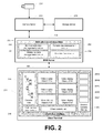
- FIG. 2 illustrates components of an exemplary DVM system (such as the system of FIG. 1 ), but simplified to illustrate components relevant to a user interface.
- a camera 201 is associated with a camera server 202.
- Camera server 202 is configured to access video data made available by camera 201, either for live viewing or for recording to a storage device 203.
- Camera server 202 is configured/controlled by a DVM server 204. There are typically a large number of cameras and camera servers configured/controlled by DVM server 204 (although only one is shown in FIG. 2 ).
- DVM server 204 executes a plurality of DVM administration modules 205.
- the functional block for modules 205 is used to simplistically represent a wide range of software components implemented within a DVM system. Only a selection of these are shown, being:
- DVM server 204 communicates with a user interface 210 which executes on a client terminal 211.
- this user interface is provided via module 230 via a web-server type arrangement (i.e. user interface 210 is provided via a web-browser at terminal 211 which renders data transmitted by server 211).
- module 230 is configured to allow a plurality of terminals 211 to independently provide respective instantiations user interface 210 for a respective plurality of operators.
- User interface 210 is configured to display live and recorded video data to a user via a video display objects (and, in some embodiments, other DVM content such as screenshots, maps, and the like).
- a plurality of video display objects are shown as being rendered on-screen simultaneously. This is described herein as a "multi-camera view”.
- the term "multi-camera view" is used to describe a camera workspace area of a user interface that displays a plurality of video display objects, each of these being configured to display live video data from an associated camera.
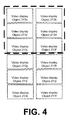
- the camera workspace displays six video display objects (213a to 213f). There may be additional video display objects that are not shown (but would be revealed via a scrolling operation). These are defined in the camera workspace, but not viewed on-screen at the instant of FIG. 2 .
- User interface 210 provides various controls 217 (which simplistically represents a variety of GUI controls available to an operator of terminal 211, such as record control, camera position control, camera view selection, and so on).
- User interface 210 also provides a camera tree 280 (supported by module 252), which groups cameras of the DVM system into a hierarchical tree structure.
- a variety of tree structures may be used, and that the groupings may be configured in a variety of ways (for example grouping based on locations in a facility, groupings based on purpose, and so on).
- the tree structure includes a plurality of expandable/collapsible nodes, and cameras are nested beneath these noted. Selecting a given node results in selection of all cameras underlying that node (directly or indirectly).
- a multi-camera view control object 216 provides controls relevant to the formation, accessing and/or management of multi camera views. This is discussed in more detail further below. In some cases such control is achieved via "right-click" functionalities or the like, as opposed to necessitating a discrete portion of the screen devoted to an object for containing such controls.
- a related camera display 260 provides data indicative of a set of "related cameras”. In the case of FIG. 2 , this provides preview video display objects 261A to 261E, which provide live view from a set of related cameras determined via the operation of module 251.
- a DVM system for example in the context of a security system, requires a large amount of configuration in order to be used effectively.
- the creation of these views is time intensive and also usually static - the creator needs to have a good understanding of the site and the upcoming security needs in order to create the correct views containing the cameras the operators will need. As the site changes or new needs arise, new views can be necessary requiring further configuration which may incur a site more costs in maintenance.
- a user is enabled to select a set of cameras in tree structure 280 (for example by selecting one or more nodes, and/or by selecting one or more individual cameras), and then operating controls 216 thereby to create a multi-camera view containing those cameras.
- Module 250 is configured to determine an appropriate layout for a multi-camera view (for example based on the number of cameras, available screen area for a camera workspace view, and based on user-defined parameters) and then define video display objects associated with the relevant cameras.
- the multi-camera view is larger than the available screen area for a camera workspace view. In such cases either or both of the following is used:
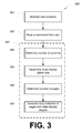
- One embodiment provides a method 300 for providing access to live video data from a plurality of cameras in a DVM system, as shown in FIG. 3 .
- Functional block 301 represents a process including maintaining data indicative of cameras in a hierarchical structure. Preferably this tree structure is generated during configuration of the DVM system.
- Functional block 302 represents a process including receiving, from a user of a client terminal, a command indicative of:
- This command is referred to as a "multi-camera view command”, and may include a command to create a new multi camera view based on the selected cameras, or add the selected cameras to an existing multi camera view.
- the hierarchical structure is defined by a tree structure including a plurality of nodes, and wherein the command is indicative of a user-selected one or more of the nodes, wherein the defined selection of cameras consists of all cameras nested beneath the user-selected one or more nodes.
- functional block 303 represents a process including defining a camera workspace view for rendering at the client terminal. This is preferably performed by module 250.
- the camera workspace view is configured to provide a plurality of video display objects that are respectively configured to display live video data from the defined selection of cameras.
- Functional block 303 includes the following sub-processes:
- Module 250 preferably allows for a defined multi-camera view to be saved for subsequent use. This is preferably saved so as to be associated with the creating user/workstation operating the user interface, so that individual users (or individual workstations) can customize their own multi-camera views. Preferably multi-camera views are able to be shared between users and/or workstations.
- FIG. 3 may be implemented thereby to enable one-click creation of a view including all cameras from one facility location, selection and creation of a view including multiple disparate cameras from one or more facility locations, and/or freeform creation or modification of a view of any configuration using multiple cameras.
- the method of FIG. 3 is also of utility in the context of camera health checks (whereby a user physically inspects the feed from each individual camera to assess whether the camera is operational and correctly directed). Specifically, by selecting the top node of the camera tree, and instructing to generate a multi camera view, the system automatically created a camera health check view containing every camera in the system. Through selection of a location lower in the tree (e.g. a level, or a section) the operator can run a health check for a smaller part of the facility, allowing operators to complete the task in tandem, or for pieces of the task to be completed at different times.
- a location lower in the tree e.g. a level, or a section
- the system would show a portion of the cameras at a suitable viewing size, and automatically create other pages of cameras that would cycle past the operator using a set cycle time. This allows:
- the system while programmed to automatically cycle through cameras to provide a complete health check, the system is configured to automatically pause cycling based on user interaction. For example, the operator may wish to use the pan, tilt, zoom or preset functionality on the camera to correct an error in field of view. If the user begins this process, the system is configured to pause cycling to ensure the operator can complete their work. The operator can then re-start the cycling process when they are happy to continue.
- the system must manage the performance, given that extremely large numbers of cameras can be added to a camera health check or multi-camera view.
- a DVM system cannot typically perform affectively if, say, one thousand cameras are trying to stream at one time. Therefore, the system is preferably configured to provide a throttling mechanism as described above to ensure that only cameras in view or about to come into view are streaming to normal effect (so that the operator does not need to wait for a connection, slowing down the process).
- the tree structure is configured to enable a user, with one or a few interactions, to select cameras from one or more locations. Using multiple simple interactions (single click, double click, drag) they can send these cameras to view in different ways, such as:
- sources other than a tree structure may be used.
- this could be any of a number of things such as another camera collection, a list, cameras linked to a map location, an alarm group, and so on.
- each video display object provides (directly or by association) a camera views inside the workspace view.
- Each camera view preferably provides functionality related to the camera that the operator can manipulate to complete tasks. For example, in the case of the camera health check, PTZ and preset functionality would be available to allow the operator to correct field of view issues. Also, video quality functionality may be available to allow the operator to correct video quality issues.
- a "related camera display” is a user interface component configured to display data indicative of one or more cameras (for example names, details and/or a live video preview) that are determined to be "related" to a camera being viewed in a primary camera workspace (which may include a multi-camera view as shown in FIG. 2 ).
- the term "related camera” is used to describe a camera determined to be “related” subject to the operation of a relationship determination module, which is configured to perform analysis for each camera in a DVM system thereby to identify, for that camera, one or more related cameras.
- security systems generally have a fixed structure of cameras from which the operator must select cameras to view (e.g. a tree structure as shown in FIG. 2 ). These are generally structured based on the physical location of a camera. These trees can contain upwards of 1000 cameras in, often in complicated structures. Each time a new camera is required, the user must return to the tree, find it and send it to view. The user must understand from their current position, what camera is likely to be used next based on their experience, or hopefully an efficient camera tree structure which allows for quick access to relevant cameras.
- related camera management module 251 is configured to maintain data indicative of related cameras for each camera in a DVM system. These may include cameras which have some kind of important relationship to a given camera.
- a learning algorithm is applied thereby to enable identification of camera relationships on an ongoing basis based upon user interaction with the DVM system. For example, one approach is to maintain, for each camera, a "relatedness score" for other cameras in the system. Those cameras with the highest relatedness score are displayed in display 260. Criteria for adding to a relatedness score for a target camera may be based upon any one or more of the following:
- configuration data is used to impact upon relatedness scores, for example based upon specific user input, relative camera locations, and so on.
- the presently described approach to camera relationships is advantageous in the sense that, if a security system can recommend important related cameras to the user, they can move from camera to camera much quicker than using their own searching and experience to find the next camera. This can be crucial when tracking a suspect from camera to camera, and allows operators to adapt to a new facility without needing to develop extensive experiential knowledge of camera and location relationships.
- a list of related cameras can also double as an expanded security view including video display objects.
- video representations are used, there are more cameras in the user's view and any situation identified in these cameras can be acted upon much faster than a camera hidden in a tree.
- display 260 includes a scrolling panel displayed beside the video area in a surveillance system.
- the panel includes small video display objects representing each related camera. When a camera is displayed or focused in the main workspace area, the cameras shown in the "related" panel changes to that context.
- processor may refer to any device or portion of a device that processes electronic data, e.g., from registers and/or memory to transform that electronic data into other electronic data that, e.g., may be stored in registers and/or memory.
- a "computer” or a “computing machine” or a “computing platform” may include one or more processors.
- the methodologies described herein are, in one embodiment, performable by one or more processors that accept computer-readable (also called machine-readable) code containing a set of instructions that when executed by one or more of the processors carry out at least one of the methods described herein.
- Any processor capable of executing a set of instructions (sequential or otherwise) that specify actions to be taken are included.
- a typical processing system that includes one or more processors.
- Each processor may include one or more of a CPU, a graphics processing unit, and a programmable DSP unit.
- the processing system further may include a memory subsystem including main RAM and/or a static RAM, and/or ROM.
- a bus subsystem may be included for communicating between the components.
- the processing system further may be a distributed processing system with processors coupled by a network. If the processing system requires a display, such a display may be included, e.g., a liquid crystal display (LCD) or a cathode ray tube (CRT) display. If manual data entry is required, the processing system also includes an input device such as one or more of an alphanumeric input unit such as a keyboard, a pointing control device such as a mouse, and so forth.
- the processing system in some configurations may include a sound output device, and a network interface device.
- the memory subsystem thus includes a computer-readable carrier medium that carries computer-readable code (e.g., software) including a set of instructions to cause performing, when executed by one or more processors, one of more of the methods described herein.
- computer-readable code e.g., software
- the software may reside in the hard disk, or may also reside, completely or at least partially, within the RAM and/or within the processor during execution thereof by the computer system.
- the memory and the processor also constitute computer-readable carrier medium carrying computer-readable code.
- a computer-readable carrier medium may form, or be included in a computer program product.
- the one or more processors operate as a standalone device or may be connected, e.g., networked to other processor(s), in a networked deployment, the one or more processors may operate in the capacity of a server or a user machine in server-user network environment, or as a peer machine in a peer-to-peer or distributed network environment.
- the one or more processors may form a personal computer (PC), a tablet PC, a set-top box (STB), a Personal Digital Assistant (PDA), a cellular telephone, a web appliance, a network router, switch or bridge, or any machine capable of executing a set of instructions (sequential or otherwise) that specify actions to be taken by that machine.
- PC personal computer
- PDA Personal Digital Assistant
- machine shall also be taken to include any collection of machines that individually or jointly execute a set (or multiple sets) of instructions to perform any one or more of the methodologies discussed herein.
- each of the methods described herein is in the form of a computer-readable carrier medium carrying a set of instructions, e.g., a computer program that is for execution on one or more processors, e.g., one or more processors that are part of web server arrangement.
- a computer-readable carrier medium carrying computer readable code including a set of instructions that when executed on one or more processors cause the processor or processors to implement a method.
- aspects of the present invention may take the form of a method, an entirely hardware embodiment, an entirely software embodiment or an embodiment combining software and hardware aspects.
- the present invention may take the form of carrier medium (e.g., a computer program product on a computer-readable storage medium) carrying computer-readable program code embodied in the medium.
- the software may further be transmitted or received over a network via a network interface device.
- the carrier medium is shown in an exemplary embodiment to be a single medium, the term “carrier medium” should be taken to include a single medium or multiple media (e.g., a centralized or distributed database, and/or associated caches and servers) that store the one or more sets of instructions.
- the term “carrier medium” shall also be taken to include any medium that is capable of storing, encoding or carrying a set of instructions for execution by one or more of the processors and that cause the one or more processors to perform any one or more of the methodologies of the present invention.
- a carrier medium may take many forms, including but not limited to, non-volatile media, volatile media, and transmission media.
- Non-volatile media includes, for example, optical, magnetic disks, and magneto-optical disks.
- Volatile media includes dynamic memory, such as main memory.
- Transmission media includes coaxial cables, copper wire and fiber optics, including the wires that comprise a bus subsystem. Transmission media also may also take the form of acoustic or light waves, such as those generated during radio wave and infrared data communications.
- carrier medium shall accordingly be taken to included, but not be limited to, solid-state memories, a computer product embodied in optical and magnetic media; a medium bearing a propagated signal detectable by at least one processor of one or more processors and representing a set of instructions that, when executed, implement a method; a carrier wave bearing a propagated signal detectable by at least one processor of the one or more processors and representing the set of instructions a propagated signal and representing the set of instructions; and a transmission medium in a network bearing a propagated signal detectable by at least one processor of the one or more processors and representing the set of instructions.
- an element described herein of an apparatus embodiment is an example of a means for carrying out the function performed by the element for the purpose of carrying out the invention.
- Coupled when used in the claims, should not be interpreted as being limited to direct connections only.
- the terms “coupled” and “connected,” along with their derivatives, may be used. It should be understood that these terms are not intended as synonyms for each other.
- the scope of the expression a device A coupled to a device B should not be limited to devices or systems wherein an output of device A is directly connected to an input of device B. It means that there exists a path between an output of A and an input of B which may be a path including other devices or means.
- Coupled may mean that two or more elements are either in direct physical or electrical contact, or that two or more elements are not in direct contact with each other but yet still co-operate or interact with each other.
Landscapes
- Engineering & Computer Science (AREA)
- Multimedia (AREA)
- Signal Processing (AREA)
- Human Computer Interaction (AREA)
- Databases & Information Systems (AREA)
- Physics & Mathematics (AREA)
- General Physics & Mathematics (AREA)
- Closed-Circuit Television Systems (AREA)
Applications Claiming Priority (1)
| Application Number | Priority Date | Filing Date | Title |
|---|---|---|---|
| AU2013900299A AU2013900299A0 (en) | 2013-01-31 | Systems and methods for managing access to surveillance cameras |
Publications (3)
| Publication Number | Publication Date |
|---|---|
| EP2763409A2 true EP2763409A2 (fr) | 2014-08-06 |
| EP2763409A3 EP2763409A3 (fr) | 2014-08-27 |
| EP2763409B1 EP2763409B1 (fr) | 2019-10-23 |
Family
ID=50115679
Family Applications (1)
| Application Number | Title | Priority Date | Filing Date |
|---|---|---|---|
| EP14153282.0A Active EP2763409B1 (fr) | 2013-01-31 | 2014-01-30 | Systèmes et procédés de gestion d'accès à des caméras de surveillance |
Country Status (2)
| Country | Link |
|---|---|
| US (1) | US20140211027A1 (fr) |
| EP (1) | EP2763409B1 (fr) |
Families Citing this family (11)
| Publication number | Priority date | Publication date | Assignee | Title |
|---|---|---|---|---|
| WO2013020165A2 (fr) | 2011-08-05 | 2013-02-14 | HONEYWELL INTERNATIONAL INC. Attn: Patent Services | Systèmes et procédés de gestion de données vidéo |
| US10523903B2 (en) | 2013-10-30 | 2019-12-31 | Honeywell International Inc. | Computer implemented systems frameworks and methods configured for enabling review of incident data |
| JP6747158B2 (ja) * | 2016-08-09 | 2020-08-26 | ソニー株式会社 | マルチカメラシステム、カメラ、カメラの処理方法、確認装置および確認装置の処理方法 |
| KR102673036B1 (ko) * | 2016-12-06 | 2024-06-05 | 한화비전 주식회사 | 데이터 관리 장치 및 방법 |
| US20190347915A1 (en) * | 2018-05-11 | 2019-11-14 | Ching-Ming Lai | Large-scale Video Monitoring and Recording System |
| EP3668087A1 (fr) * | 2018-12-14 | 2020-06-17 | Carrier Corporation | Espace de travail de système de surveillance vidéo |
| JP2021027579A (ja) * | 2019-07-31 | 2021-02-22 | 株式会社リコー | 画像判定装置および画像判定システム |
| US12094309B2 (en) * | 2019-12-13 | 2024-09-17 | Sony Group Corporation | Efficient user interface navigation for multiple real-time streaming devices |
| US11086491B1 (en) | 2020-01-21 | 2021-08-10 | Honeywell International Inc. | Systems and methods for displaying video streams on a display |
| WO2021241550A1 (fr) * | 2020-05-29 | 2021-12-02 | 日本電気株式会社 | Dispositif de gestion de vidéos, procédé de gestion de vidéos, et programme |
| JP2025030472A (ja) * | 2023-08-23 | 2025-03-07 | キヤノン株式会社 | 制御システム、撮像装置及びその制御方法、プログラム |
Family Cites Families (16)
| Publication number | Priority date | Publication date | Assignee | Title |
|---|---|---|---|---|
| AUPQ217399A0 (en) * | 1999-08-12 | 1999-09-02 | Honeywell Limited | Realtime digital video server |
| CA2391410A1 (fr) * | 1999-12-03 | 2001-06-07 | Ourworld Live, Inc. | Systemes d'acces aux consommateurs et leurs procedes de fourniture |
| EP1872345B1 (fr) * | 2005-03-25 | 2011-03-02 | Sensormatic Electronics, LLC | Selection de cameras et suivi d'objets intelligents |
| US9036028B2 (en) * | 2005-09-02 | 2015-05-19 | Sensormatic Electronics, LLC | Object tracking and alerts |
| EP1958420A2 (fr) * | 2005-12-04 | 2008-08-20 | Turner Broadcast System, Inc (TBS, Inc.) | Systeme et procede de distribution de contenu video et audio sur un reseau |
| US7468662B2 (en) * | 2006-06-16 | 2008-12-23 | International Business Machines Corporation | Method for spatio-temporal event detection using composite definitions for camera systems |
| US8274564B2 (en) * | 2006-10-13 | 2012-09-25 | Fuji Xerox Co., Ltd. | Interface for browsing and viewing video from multiple cameras simultaneously that conveys spatial and temporal proximity |
| US20090079831A1 (en) * | 2007-09-23 | 2009-03-26 | Honeywell International Inc. | Dynamic tracking of intruders across a plurality of associated video screens |
| JP4987757B2 (ja) * | 2008-03-03 | 2012-07-25 | 株式会社日立国際電気 | 映像表示装置 |
| US8531522B2 (en) * | 2008-05-30 | 2013-09-10 | Verint Systems Ltd. | Systems and methods for video monitoring using linked devices |
| US8340654B2 (en) * | 2009-05-26 | 2012-12-25 | Lextech Labs Llc | Apparatus and method for video display and control for portable device |
| US10084993B2 (en) * | 2010-01-14 | 2018-09-25 | Verint Systems Ltd. | Systems and methods for managing and displaying video sources |
| US8922658B2 (en) * | 2010-11-05 | 2014-12-30 | Tom Galvin | Network video recorder system |
| WO2012174603A1 (fr) * | 2011-06-24 | 2012-12-27 | Honeywell International Inc. | Systèmes et procédés de présentation d'informations de système dvm |
| US8893184B2 (en) * | 2011-07-15 | 2014-11-18 | Intel Corporation | Mechanism for facilitating multiple multimedia viewing planes in media display systems |
| US8935725B1 (en) * | 2012-04-16 | 2015-01-13 | Google Inc. | Visually browsing videos |
-
2014
- 2014-01-30 US US14/169,104 patent/US20140211027A1/en not_active Abandoned
- 2014-01-30 EP EP14153282.0A patent/EP2763409B1/fr active Active
Non-Patent Citations (1)
| Title |
|---|
| None |
Also Published As
| Publication number | Publication date |
|---|---|
| EP2763409B1 (fr) | 2019-10-23 |
| EP2763409A3 (fr) | 2014-08-27 |
| US20140211027A1 (en) | 2014-07-31 |
Similar Documents
| Publication | Publication Date | Title |
|---|---|---|
| EP2763409B1 (fr) | Systèmes et procédés de gestion d'accès à des caméras de surveillance | |
| US10863143B2 (en) | Systems and methods for managing video data | |
| US11632516B2 (en) | Capture, analysis and use of building data from mobile devices | |
| US11523088B2 (en) | Computer implemented systems frameworks and methods configured for enabling review of incident data | |
| CN111095871B (zh) | 有助于网络数据流分析的时间图系统 | |
| US9344684B2 (en) | Systems and methods configured to enable content sharing between client terminals of a digital video management system | |
| US10038872B2 (en) | Systems and methods for managing video data | |
| US9076259B2 (en) | Geospatial multiviewer | |
| EP2452489B1 (fr) | Systèmes et procédés de gestion de données vidéo | |
| US10521481B2 (en) | Video-production system with social-media features | |
| US12112435B1 (en) | Collaboration spaces in extended reality conference sessions | |
| WO2022205798A1 (fr) | Procédé d'édition d'informations multimédias et appareil associé | |
| CA2992484A1 (fr) | Systeme de production video avec des caracteristiques de reseau social | |
| JP2017517789A (ja) | ビデオコンテンツの時間ベース及び地理的ナビゲーションのための方法、装置並びにシステム | |
| US11977805B2 (en) | Systems and methods for displaying facility information | |
| CN115269916A (zh) | 信息显示方法、装置、存储介质及电子设备 | |
| US9894261B2 (en) | Systems and methods for presenting digital video management system information via a user-customizable hierarchical tree interface | |
| US20200104024A1 (en) | Communication terminal, information sharing system, display control method, and non-transitory computer-readable medium | |
| RU2748176C1 (ru) | Система и способ настройки отображения данных на видеостене | |
| CN115509993A (zh) | 三维全景图预加载、分组管理、热点动态标注方法和系统 | |
| US11949730B2 (en) | Context-aware interface layer for remote applications | |
| KR20250025144A (ko) | 복수의 촬영지 및 제어지 간의 영상정보 및 제어정보의 송신 및 수신을 통한 실시간 다중채널 촬영 및 제어 서비스를 제공하는 장치 | |
| KR20250025143A (ko) | 복수의 촬영지 및 제어지 간의 영상정보 및 제어정보의 송신 및 수신을 통한 실시간 다중채널 촬영 및 제어 서비스를 제공하는 방법 | |
| CN116418859A (zh) | 一种基于ar的智能运检系统 |
Legal Events
| Date | Code | Title | Description |
|---|---|---|---|
| PUAL | Search report despatched |
Free format text: ORIGINAL CODE: 0009013 |
|
| PUAI | Public reference made under article 153(3) epc to a published international application that has entered the european phase |
Free format text: ORIGINAL CODE: 0009012 |
|
| 17P | Request for examination filed |
Effective date: 20140130 |
|
| AK | Designated contracting states |
Kind code of ref document: A2 Designated state(s): AL AT BE BG CH CY CZ DE DK EE ES FI FR GB GR HR HU IE IS IT LI LT LU LV MC MK MT NL NO PL PT RO RS SE SI SK SM TR |
|
| AX | Request for extension of the european patent |
Extension state: BA ME |
|
| AK | Designated contracting states |
Kind code of ref document: A3 Designated state(s): AL AT BE BG CH CY CZ DE DK EE ES FI FR GB GR HR HU IE IS IT LI LT LU LV MC MK MT NL NO PL PT RO RS SE SI SK SM TR |
|
| AX | Request for extension of the european patent |
Extension state: BA ME |
|
| RIC1 | Information provided on ipc code assigned before grant |
Ipc: H04N 7/18 20060101AFI20140723BHEP Ipc: G08B 13/196 20060101ALI20140723BHEP Ipc: H04N 5/232 20060101ALI20140723BHEP |
|
| 17Q | First examination report despatched |
Effective date: 20140905 |
|
| RAP1 | Party data changed (applicant data changed or rights of an application transferred) |
Owner name: HONEYWELL INTERNATIONAL INC. |
|
| STAA | Information on the status of an ep patent application or granted ep patent |
Free format text: STATUS: EXAMINATION IS IN PROGRESS |
|
| REG | Reference to a national code |
Ref country code: DE Ref legal event code: R079 Ref document number: 602014055468 Country of ref document: DE Free format text: PREVIOUS MAIN CLASS: H04N0007180000 Ipc: H04N0021218700 |
|
| GRAP | Despatch of communication of intention to grant a patent |
Free format text: ORIGINAL CODE: EPIDOSNIGR1 |
|
| STAA | Information on the status of an ep patent application or granted ep patent |
Free format text: STATUS: GRANT OF PATENT IS INTENDED |
|
| RIC1 | Information provided on ipc code assigned before grant |
Ipc: H04N 21/238 20110101ALI20190516BHEP Ipc: H04N 21/431 20110101ALI20190516BHEP Ipc: H04N 21/2187 20110101AFI20190516BHEP Ipc: G08B 13/196 20060101ALI20190516BHEP Ipc: H04N 21/485 20110101ALI20190516BHEP Ipc: H04N 7/18 20060101ALI20190516BHEP Ipc: H04N 5/232 20060101ALI20190516BHEP |
|
| INTG | Intention to grant announced |
Effective date: 20190604 |
|
| GRAS | Grant fee paid |
Free format text: ORIGINAL CODE: EPIDOSNIGR3 |
|
| GRAA | (expected) grant |
Free format text: ORIGINAL CODE: 0009210 |
|
| STAA | Information on the status of an ep patent application or granted ep patent |
Free format text: STATUS: THE PATENT HAS BEEN GRANTED |
|
| AK | Designated contracting states |
Kind code of ref document: B1 Designated state(s): AL AT BE BG CH CY CZ DE DK EE ES FI FR GB GR HR HU IE IS IT LI LT LU LV MC MK MT NL NO PL PT RO RS SE SI SK SM TR |
|
| REG | Reference to a national code |
Ref country code: GB Ref legal event code: FG4D |
|
| REG | Reference to a national code |
Ref country code: CH Ref legal event code: EP |
|
| REG | Reference to a national code |
Ref country code: IE Ref legal event code: FG4D |
|
| REG | Reference to a national code |
Ref country code: DE Ref legal event code: R096 Ref document number: 602014055468 Country of ref document: DE |
|
| REG | Reference to a national code |
Ref country code: AT Ref legal event code: REF Ref document number: 1195024 Country of ref document: AT Kind code of ref document: T Effective date: 20191115 |
|
| REG | Reference to a national code |
Ref country code: NL Ref legal event code: MP Effective date: 20191023 |
|
| REG | Reference to a national code |
Ref country code: LT Ref legal event code: MG4D |
|
| PG25 | Lapsed in a contracting state [announced via postgrant information from national office to epo] |
Ref country code: NO Free format text: LAPSE BECAUSE OF FAILURE TO SUBMIT A TRANSLATION OF THE DESCRIPTION OR TO PAY THE FEE WITHIN THE PRESCRIBED TIME-LIMIT Effective date: 20200123 Ref country code: GR Free format text: LAPSE BECAUSE OF FAILURE TO SUBMIT A TRANSLATION OF THE DESCRIPTION OR TO PAY THE FEE WITHIN THE PRESCRIBED TIME-LIMIT Effective date: 20200124 Ref country code: PL Free format text: LAPSE BECAUSE OF FAILURE TO SUBMIT A TRANSLATION OF THE DESCRIPTION OR TO PAY THE FEE WITHIN THE PRESCRIBED TIME-LIMIT Effective date: 20191023 Ref country code: FI Free format text: LAPSE BECAUSE OF FAILURE TO SUBMIT A TRANSLATION OF THE DESCRIPTION OR TO PAY THE FEE WITHIN THE PRESCRIBED TIME-LIMIT Effective date: 20191023 Ref country code: PT Free format text: LAPSE BECAUSE OF FAILURE TO SUBMIT A TRANSLATION OF THE DESCRIPTION OR TO PAY THE FEE WITHIN THE PRESCRIBED TIME-LIMIT Effective date: 20200224 Ref country code: BG Free format text: LAPSE BECAUSE OF FAILURE TO SUBMIT A TRANSLATION OF THE DESCRIPTION OR TO PAY THE FEE WITHIN THE PRESCRIBED TIME-LIMIT Effective date: 20200123 Ref country code: LT Free format text: LAPSE BECAUSE OF FAILURE TO SUBMIT A TRANSLATION OF THE DESCRIPTION OR TO PAY THE FEE WITHIN THE PRESCRIBED TIME-LIMIT Effective date: 20191023 Ref country code: SE Free format text: LAPSE BECAUSE OF FAILURE TO SUBMIT A TRANSLATION OF THE DESCRIPTION OR TO PAY THE FEE WITHIN THE PRESCRIBED TIME-LIMIT Effective date: 20191023 Ref country code: LV Free format text: LAPSE BECAUSE OF FAILURE TO SUBMIT A TRANSLATION OF THE DESCRIPTION OR TO PAY THE FEE WITHIN THE PRESCRIBED TIME-LIMIT Effective date: 20191023 Ref country code: ES Free format text: LAPSE BECAUSE OF FAILURE TO SUBMIT A TRANSLATION OF THE DESCRIPTION OR TO PAY THE FEE WITHIN THE PRESCRIBED TIME-LIMIT Effective date: 20191023 Ref country code: NL Free format text: LAPSE BECAUSE OF FAILURE TO SUBMIT A TRANSLATION OF THE DESCRIPTION OR TO PAY THE FEE WITHIN THE PRESCRIBED TIME-LIMIT Effective date: 20191023 |
|
| PG25 | Lapsed in a contracting state [announced via postgrant information from national office to epo] |
Ref country code: HR Free format text: LAPSE BECAUSE OF FAILURE TO SUBMIT A TRANSLATION OF THE DESCRIPTION OR TO PAY THE FEE WITHIN THE PRESCRIBED TIME-LIMIT Effective date: 20191023 Ref country code: RS Free format text: LAPSE BECAUSE OF FAILURE TO SUBMIT A TRANSLATION OF THE DESCRIPTION OR TO PAY THE FEE WITHIN THE PRESCRIBED TIME-LIMIT Effective date: 20191023 Ref country code: IS Free format text: LAPSE BECAUSE OF FAILURE TO SUBMIT A TRANSLATION OF THE DESCRIPTION OR TO PAY THE FEE WITHIN THE PRESCRIBED TIME-LIMIT Effective date: 20200224 |
|
| PG25 | Lapsed in a contracting state [announced via postgrant information from national office to epo] |
Ref country code: AL Free format text: LAPSE BECAUSE OF FAILURE TO SUBMIT A TRANSLATION OF THE DESCRIPTION OR TO PAY THE FEE WITHIN THE PRESCRIBED TIME-LIMIT Effective date: 20191023 |
|
| REG | Reference to a national code |
Ref country code: DE Ref legal event code: R097 Ref document number: 602014055468 Country of ref document: DE |
|
| PG2D | Information on lapse in contracting state deleted |
Ref country code: IS |
|
| PG25 | Lapsed in a contracting state [announced via postgrant information from national office to epo] |
Ref country code: DK Free format text: LAPSE BECAUSE OF FAILURE TO SUBMIT A TRANSLATION OF THE DESCRIPTION OR TO PAY THE FEE WITHIN THE PRESCRIBED TIME-LIMIT Effective date: 20191023 Ref country code: EE Free format text: LAPSE BECAUSE OF FAILURE TO SUBMIT A TRANSLATION OF THE DESCRIPTION OR TO PAY THE FEE WITHIN THE PRESCRIBED TIME-LIMIT Effective date: 20191023 Ref country code: RO Free format text: LAPSE BECAUSE OF FAILURE TO SUBMIT A TRANSLATION OF THE DESCRIPTION OR TO PAY THE FEE WITHIN THE PRESCRIBED TIME-LIMIT Effective date: 20191023 Ref country code: CZ Free format text: LAPSE BECAUSE OF FAILURE TO SUBMIT A TRANSLATION OF THE DESCRIPTION OR TO PAY THE FEE WITHIN THE PRESCRIBED TIME-LIMIT Effective date: 20191023 Ref country code: IS Free format text: LAPSE BECAUSE OF FAILURE TO SUBMIT A TRANSLATION OF THE DESCRIPTION OR TO PAY THE FEE WITHIN THE PRESCRIBED TIME-LIMIT Effective date: 20200223 |
|
| REG | Reference to a national code |
Ref country code: AT Ref legal event code: MK05 Ref document number: 1195024 Country of ref document: AT Kind code of ref document: T Effective date: 20191023 |
|
| PLBE | No opposition filed within time limit |
Free format text: ORIGINAL CODE: 0009261 |
|
| STAA | Information on the status of an ep patent application or granted ep patent |
Free format text: STATUS: NO OPPOSITION FILED WITHIN TIME LIMIT |
|
| PG25 | Lapsed in a contracting state [announced via postgrant information from national office to epo] |
Ref country code: MC Free format text: LAPSE BECAUSE OF FAILURE TO SUBMIT A TRANSLATION OF THE DESCRIPTION OR TO PAY THE FEE WITHIN THE PRESCRIBED TIME-LIMIT Effective date: 20191023 Ref country code: IT Free format text: LAPSE BECAUSE OF FAILURE TO SUBMIT A TRANSLATION OF THE DESCRIPTION OR TO PAY THE FEE WITHIN THE PRESCRIBED TIME-LIMIT Effective date: 20191023 Ref country code: SM Free format text: LAPSE BECAUSE OF FAILURE TO SUBMIT A TRANSLATION OF THE DESCRIPTION OR TO PAY THE FEE WITHIN THE PRESCRIBED TIME-LIMIT Effective date: 20191023 Ref country code: SK Free format text: LAPSE BECAUSE OF FAILURE TO SUBMIT A TRANSLATION OF THE DESCRIPTION OR TO PAY THE FEE WITHIN THE PRESCRIBED TIME-LIMIT Effective date: 20191023 |
|
| REG | Reference to a national code |
Ref country code: CH Ref legal event code: PL |
|
| 26N | No opposition filed |
Effective date: 20200724 |
|
| REG | Reference to a national code |
Ref country code: BE Ref legal event code: MM Effective date: 20200131 |
|
| PG25 | Lapsed in a contracting state [announced via postgrant information from national office to epo] |
Ref country code: LU Free format text: LAPSE BECAUSE OF NON-PAYMENT OF DUE FEES Effective date: 20200130 |
|
| PG25 | Lapsed in a contracting state [announced via postgrant information from national office to epo] |
Ref country code: AT Free format text: LAPSE BECAUSE OF FAILURE TO SUBMIT A TRANSLATION OF THE DESCRIPTION OR TO PAY THE FEE WITHIN THE PRESCRIBED TIME-LIMIT Effective date: 20191023 Ref country code: BE Free format text: LAPSE BECAUSE OF NON-PAYMENT OF DUE FEES Effective date: 20200131 Ref country code: LI Free format text: LAPSE BECAUSE OF NON-PAYMENT OF DUE FEES Effective date: 20200131 Ref country code: SI Free format text: LAPSE BECAUSE OF FAILURE TO SUBMIT A TRANSLATION OF THE DESCRIPTION OR TO PAY THE FEE WITHIN THE PRESCRIBED TIME-LIMIT Effective date: 20191023 Ref country code: CH Free format text: LAPSE BECAUSE OF NON-PAYMENT OF DUE FEES Effective date: 20200131 |
|
| PG25 | Lapsed in a contracting state [announced via postgrant information from national office to epo] |
Ref country code: IE Free format text: LAPSE BECAUSE OF NON-PAYMENT OF DUE FEES Effective date: 20200130 |
|
| PG25 | Lapsed in a contracting state [announced via postgrant information from national office to epo] |
Ref country code: TR Free format text: LAPSE BECAUSE OF FAILURE TO SUBMIT A TRANSLATION OF THE DESCRIPTION OR TO PAY THE FEE WITHIN THE PRESCRIBED TIME-LIMIT Effective date: 20191023 Ref country code: MT Free format text: LAPSE BECAUSE OF FAILURE TO SUBMIT A TRANSLATION OF THE DESCRIPTION OR TO PAY THE FEE WITHIN THE PRESCRIBED TIME-LIMIT Effective date: 20191023 Ref country code: CY Free format text: LAPSE BECAUSE OF FAILURE TO SUBMIT A TRANSLATION OF THE DESCRIPTION OR TO PAY THE FEE WITHIN THE PRESCRIBED TIME-LIMIT Effective date: 20191023 |
|
| PG25 | Lapsed in a contracting state [announced via postgrant information from national office to epo] |
Ref country code: MK Free format text: LAPSE BECAUSE OF FAILURE TO SUBMIT A TRANSLATION OF THE DESCRIPTION OR TO PAY THE FEE WITHIN THE PRESCRIBED TIME-LIMIT Effective date: 20191023 |
|
| P01 | Opt-out of the competence of the unified patent court (upc) registered |
Effective date: 20230523 |
|
| PGFP | Annual fee paid to national office [announced via postgrant information from national office to epo] |
Ref country code: DE Payment date: 20240129 Year of fee payment: 11 |
|
| PGFP | Annual fee paid to national office [announced via postgrant information from national office to epo] |
Ref country code: FR Payment date: 20240125 Year of fee payment: 11 |
|
| PGFP | Annual fee paid to national office [announced via postgrant information from national office to epo] |
Ref country code: GB Payment date: 20250121 Year of fee payment: 12 |
|
| REG | Reference to a national code |
Ref country code: DE Ref legal event code: R119 Ref document number: 602014055468 Country of ref document: DE |
|
| PG25 | Lapsed in a contracting state [announced via postgrant information from national office to epo] |
Ref country code: DE Free format text: LAPSE BECAUSE OF NON-PAYMENT OF DUE FEES Effective date: 20250801 |
|
| PG25 | Lapsed in a contracting state [announced via postgrant information from national office to epo] |
Ref country code: FR Free format text: LAPSE BECAUSE OF NON-PAYMENT OF DUE FEES Effective date: 20250131 |