EP2763565B1 - Brosse d'application de mascara creuse - Google Patents
Brosse d'application de mascara creuse Download PDFInfo
- Publication number
- EP2763565B1 EP2763565B1 EP12780677.6A EP12780677A EP2763565B1 EP 2763565 B1 EP2763565 B1 EP 2763565B1 EP 12780677 A EP12780677 A EP 12780677A EP 2763565 B1 EP2763565 B1 EP 2763565B1
- Authority
- EP
- European Patent Office
- Prior art keywords
- applicator
- section
- cage
- ribs
- longitudinal axis
- Prior art date
- Legal status (The legal status is an assumption and is not a legal conclusion. Google has not performed a legal analysis and makes no representation as to the accuracy of the status listed.)
- Active
Links
- 210000000720 eyelash Anatomy 0.000 claims description 52
- 239000002537 cosmetic Substances 0.000 claims description 45
- 230000008878 coupling Effects 0.000 claims description 17
- 238000010168 coupling process Methods 0.000 claims description 17
- 238000005859 coupling reaction Methods 0.000 claims description 17
- 230000007423 decrease Effects 0.000 claims description 5
- 238000003860 storage Methods 0.000 claims description 5
- 230000037431 insertion Effects 0.000 claims 1
- 238000003780 insertion Methods 0.000 claims 1
- 230000008901 benefit Effects 0.000 description 8
- 239000000463 material Substances 0.000 description 6
- 230000002093 peripheral effect Effects 0.000 description 6
- 229920003023 plastic Polymers 0.000 description 5
- 239000002184 metal Substances 0.000 description 4
- 238000000034 method Methods 0.000 description 3
- 230000002411 adverse Effects 0.000 description 2
- 239000000835 fiber Substances 0.000 description 2
- 238000001746 injection moulding Methods 0.000 description 2
- 230000014759 maintenance of location Effects 0.000 description 2
- 238000004519 manufacturing process Methods 0.000 description 2
- 239000000203 mixture Substances 0.000 description 2
- 230000000149 penetrating effect Effects 0.000 description 2
- 230000008569 process Effects 0.000 description 2
- 230000009471 action Effects 0.000 description 1
- 230000001154 acute effect Effects 0.000 description 1
- 210000005242 cardiac chamber Anatomy 0.000 description 1
- 238000004040 coloring Methods 0.000 description 1
- 238000004512 die casting Methods 0.000 description 1
- 238000006073 displacement reaction Methods 0.000 description 1
- 230000000694 effects Effects 0.000 description 1
- 210000000744 eyelid Anatomy 0.000 description 1
- 229920002457 flexible plastic Polymers 0.000 description 1
- 210000004209 hair Anatomy 0.000 description 1
- 230000006872 improvement Effects 0.000 description 1
- 238000002347 injection Methods 0.000 description 1
- 239000007924 injection Substances 0.000 description 1
- 230000004048 modification Effects 0.000 description 1
- 238000012986 modification Methods 0.000 description 1
- 238000000465 moulding Methods 0.000 description 1
- 235000011837 pasties Nutrition 0.000 description 1
- 238000002360 preparation method Methods 0.000 description 1
- 238000000926 separation method Methods 0.000 description 1
- 238000009751 slip forming Methods 0.000 description 1
- 239000000243 solution Substances 0.000 description 1
Images


Classifications
-
- A—HUMAN NECESSITIES
- A46—BRUSHWARE
- A46B—BRUSHES
- A46B9/00—Arrangements of the bristles in the brush body
- A46B9/02—Position or arrangement of bristles in relation to surface of the brush body, e.g. inclined, in rows, in groups
- A46B9/021—Position or arrangement of bristles in relation to surface of the brush body, e.g. inclined, in rows, in groups arranged like in cosmetics brushes, e.g. mascara, nail polish, eye shadow
-
- A—HUMAN NECESSITIES
- A46—BRUSHWARE
- A46B—BRUSHES
- A46B11/00—Brushes with reservoir or other means for applying substances, e.g. paints, pastes, water
- A46B11/0006—Brushes with reservoir or other means for applying substances, e.g. paints, pastes, water specially adapted to feed the bristle upper surface
-
- A—HUMAN NECESSITIES
- A46—BRUSHWARE
- A46B—BRUSHES
- A46B3/00—Brushes characterised by the way in which the bristles are fixed or joined in or on the brush body or carrier
- A46B3/005—Bristle carriers and bristles moulded as a unit
-
- A—HUMAN NECESSITIES
- A46—BRUSHWARE
- A46D—MANUFACTURE OF BRUSHES
- A46D1/00—Bristles; Selection of materials for bristles
- A46D1/02—Bristles details
- A46D1/0253—Bristles having a shape which is not a straight line, e.g. curved, "S", hook, loop
-
- A—HUMAN NECESSITIES
- A46—BRUSHWARE
- A46B—BRUSHES
- A46B15/00—Other brushes; Brushes with additional arrangements
- A46B15/0055—Brushes combined with other articles normally separate from the brushing process, e.g. combs, razors, mirrors
- A46B15/0059—Brushes with a comb
-
- A—HUMAN NECESSITIES
- A46—BRUSHWARE
- A46B—BRUSHES
- A46B2200/00—Brushes characterized by their functions, uses or applications
- A46B2200/10—For human or animal care
- A46B2200/1046—Brush used for applying cosmetics
- A46B2200/1053—Cosmetics applicator specifically for mascara
- A46B2200/106—Cosmetics applicator specifically for mascara including comb like element
Definitions
- the invention relates to an applicator according to the preamble of claim 1.
- Such an applicator is used for applying cosmetic to keratinic fibers and in particular for applying mascara to the eyelashes of the human eye.
- disc applicators are known in addition to bristled applicators.
- the actual applicator section has, in such disk applicators, a core with a not inconsiderable thickness, from which a number of disks or disk sections project radially outwardly. Between adjacent discs or disc elements each have a free space is provided. In particular, in this free space remains even after pulling out of the applicator from the cosmetics reservoir and after stripping the applicator of the majority of the applied cosmetic mass.
- document JP2000023738 discloses an applicator for applying cosmetic to eyelashes according to the preamble of claims 1 and 2.
- an applicator for applying cosmetic to eyelashes having a shaft portion or at least a coupling portion and an applicator portion.
- the applicator section is designed as a circumferentially substantially or completely self-contained, inside hollow cage for receiving the cosmetic.
- such an applicator is characterized in that the cage has a triangular cross-section in the direction perpendicular to its longitudinal axis L, and an alternating sequence of ribs and passages communicating with the interior of the cage is provided on at least one of its tips which meet at its circumference has, in which insert the eyelashes in the application.
- a tip equipped with passages can be brought much closer to the lid-side approach of the eyelashes than a uniform cylindrical applicator - since only the tip is particularly close to the eye, but not the entire applicator. This is considered essential by the users felt more pleasant. In addition, such a tip is usually also very good for combing the eyelashes.
- the applicator according to the invention is characterized in that the extent of the ribs measured in the direction of the longitudinal axis of the applicator is reduced from the respective rib base point to the respective rib apex.
- the passage between two ribs adjacent in the direction parallel to the longitudinal axis is greater than the extent of a single rib in the direction parallel to the longitudinal axis.
- an applicator which is likewise designed as a circumferentially substantially or completely self-contained, inside hollow cage for receiving the cosmetic.
- This bulge like the apex of a triangular cross-section, protrudes outwards and has a number of passages communicating with the interior of the cage into which the eyelashes engage during application.
- the classic heart shape is a preferred embodiment of such a cross-section with a V-shaped bulge - the tip of the heart forms the said V-shaped bulge, which can be easily brought very close to the lid-side approach of the eyelashes and therefore functionally the tip of the initially described triangular cross-section corresponds.
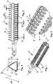
- the Fig. 1 to 4 show a first embodiment of the invention.
- the actual applicator 1 consists of an applicator section 2 in the form of the cage K, which is to be explained in more detail below, and which is preferably completely coreless Coupling section 3.
- the coupling section 3 of the applicator 1 is coupled to a handle, not shown here, which establishes a connection with the handle, also not shown here.
- the proximal end face 4a of the applicator section 2 adjoins the coupling section 3, i. the end face facing the coupling portion 3.
- three carrier elements 5 are fastened to this proximal end face 4 a, preferably by integral production with the end face 4 a by injection molding.
- the proximal end face 4a is completely self-contained and thereby retains the cosmetic mass penetrating into the cavity of the cage K.
- the distal end face 4b of the applicator section is essentially completely open and thus offers a large cross section through which the cosmetic mass can penetrate into the interior of the cage K when re-inserting the applicator section 2.
- the individual peripheral surfaces which bound the triangular cage are preferably convex or concave (cf. FIG. 4 ), wherein the radius of curvature KR, which specifies this convex or concave curvature, preferably at least by a factor of 2.5, better by at least the factor 3 is greater than the maximum extent D of the cage perpendicular to the longitudinal axis L.
- the coupling portion 3 and the applicator portion 2 of this embodiment may be integrally molded of a plastic material.
- the clear inner cross section of the cage then has a slight conicity, ie the clear internal cross-section of the cage increases slightly towards the distal end of the cage.
- the wall sections of the cage preferably have substantially all the same wall thickness.
- Each of these wall sections forming a support element 5 preferably lies centrally on one of the flat or slightly convex or concave peripheral surfaces of the cage.
- the ribs are evenly or substantially evenly distributed circumferentially.
- Cage structures of a number of parallel arranged, triangular ribs 6, which are interconnected only on one side by means of a support member are not excluded a priori, but not preferred.
- each rib is zwekelnkelig and the two legs of the respective Rippenfußddling 8 and 9 go out and meet at the apex 10 of the respective rib, with each other include an acute angle ß, which is preferably less than or equal to 80 degrees, see.
- FIG. 4
- the triangular cage in each of its tip areas is circumferentially outwardly open, so identifies at each of its tip areas an alternating sequence of ribs 6 and 7 passages.
- the triangular cage may be sufficient in certain cases, however, if the triangular cage is only peripherally open to the outside in one of its tip areas, then one must rather speak of a unilaterally opened triangular tube.
- such an embodiment is not preferred.
- each rib 6 preferably has a flattening or rounding which will normally be dimensioned so that the apices 10 do not create an unpleasant "prick" when they come in contact with the sensitive eyelid.
- the extension of the ribs 6 decreases from the respective rib base point to the respective rib apex.
- the free space between two ribs 6 adjacent in the longitudinal direction L forms in each case a v-shaped passage 7, ie a passage which is predestined to "catch" eyelashes.
- Such a round applicator would have one extremely small diameter have to be able to be introduced comparably close to the eyelash extension.
- the choice of an extremely small diameter would then adversely affect its mass storage capacity, since the free interior of the cage is getting smaller, the more the diameter decreases.
- the rib distance RA in the region of adjacent rib apexes 10 is at least 3 times, better still at least 4 times, the rib extension RD in the region of the rib apex measured in the direction parallel to the longitudinal axis L.
- the rib distance RA is in this case Embodiment in the region of adjacent rib base points (above the foot-side rounding) preferably at least 0.75 times, more preferably at least 1.25 times, the rib extension RD in this area, measured in the direction parallel to the longitudinal axis L.
- the cage consists of at least one, preferably three rows of 10 to 30, preferably 12 to 20 in the longitudinal direction L successively arranged ribs 6. Ideally, all ribs are the same.
- the cross-section of the cage does not form an equilateral triangle, but a triangle in which at least one side length is greater than the other two side lengths.
- At least one side of the triangle has an edge length KL of ⁇ 12 mm, better still an edge length KL of ⁇ 8 mm.
- the extension of the applicator 2 in the direction of its longitudinal axis is preferably ⁇ 35 mm, excluding the coupling section, better still ⁇ 30 mm.
- the cross-sectional area of the individual ribs in coordination with the material used for the ribs is preferably chosen so small that the individual ribs are not completely rigid, but by the scraper while stripping a bit to the side in the direction of Longitudinal axis L of the applicator can be bent.
- each individual rib is dimensioned in coordination with the rib material so that the rib can move in the region of its rib apex by an amount B in the direction of the longitudinal axis L.
- the FIG. 3 illustrates what is meant here.
- the amount B preferably corresponds at least to the extent of the individual rib in the direction of the longitudinal axis L and preferably even twice or ideally even at least three times this extent.
- the cage K formed in the described manner from the support sections 5 and the connecting ribs 6 is thin-walled in relation to its diameter - the wall thickness of the cage-forming ribs in the radial direction nowhere more than 17.5% of the cage diameter, preferably even nowhere more than 10% of the cage diameter.
- Under the cage diameter is at a non-circular applicator cross section understood the diameter of that imaginary circle having the same area as the actual cage cross-section.
- the proportion of the outwardly facing rib surface on the entire outer peripheral surface of the cage K is preferably smaller than the imaginary surface defining the apertures 7 on the outer peripheral surface of the Occupy cage K.
- the ratio "rib surface" to "area of the apertures" is even less than 40%.
- ribs which form one side of the triangular cross-section can be designed so that they form an additional groove 16, as they will be explained in more detail in the context of the fourth embodiment Fig. 13 to 16 is shown graphically. What has been said in the context of the fourth embodiment applies mutatis mutandis.
- a variant of the applicator according to the invention is produced in the so-called two-component injection molding process.
- the carrier elements 5, which make up the essential part of its rigidity and / or dimensional stability are first injection-molded from a harder and / or more rigid plastic.
- the existing of a softer and / or more flexible plastic ribs are molded. In this way, the individual application properties of the applicator can be precisely adjusted.
- the applicator shown by this embodiment does not have to be a preferably one-piece plastic injection molded part be executed, even if such a method of production is of course very advantageous from a cost point of view.
- High-priced applicators of this kind can instead also be made of metal.
- such an applicator section made of metal is given a finish by rotating with its outermost periphery past a grinding wheel so that its pointed apex areas are rounded off, which ensures a more pleasant feeling of application and greater safety.
- the Fig. 5 to 8 show a second embodiment of the invention, which substantially corresponds to the first embodiment and for which therefore the same applies in connection with the first embodiment.
- the cage is not completely self-contained in the circumferential direction in this embodiment, but instead exceptionally and in contrast to all other embodiments has a longitudinally across the width of several ribs passing slot, as the best in Fig. 5 can be seen.
- the slot is preferably designed so narrow that the effect that the interior of the cage is loaded when inserting the Applikatorabitess in a cosmetic stock with cosmetics, is not significantly affected.
- the slot is how one uses the Fig. 8 sees, in this embodiment by rudimentary trained Rib portions 12 limited, the free cantilever ends at the edges of the slot S.
- FIGS. 9 to 12 describe a third embodiment of the invention, which is very similar to the first embodiment of the invention.
- the description already given there therefore applies to this third embodiment in a corresponding manner, as far as the features described below, by which the third embodiment differs from the first embodiment, does not result in anything else.
- the cage has a cross section corresponding to a heart shape, that is, a substantially non-triangular cross section.
- This heart-shaped cross-section translates with the heart tip the idea laid down in the claims that the cross-section of the cage perpendicular to the longitudinal axis L of the applicator section at least one substantially V-shaped bulge of two at an angle of preferably ⁇ 110 °, better ⁇ 90 ° to each other arranged surfaces which projects outwardly and which has a plurality of passages 7.
- an applicator with such a total, non-triangular cross section at least locally achieves the advantages that the triangular cross section described above has achieved.
- this heart-shaped cross section has further advantages in individual cases.
- the wall thickness of the cage is here again preferably the same everywhere. But there are a total of three areas where the cage wall has no interruptions or passages, which is why they each forms a carrier element 5 at these locations.
- the ribs 6, which form the tip of the heart-shaped cross section in this embodiment, are characterized in turn by each of these ribs 6 zwekelnkelig and the two legs, which emanate from the respective rib base 8, 9 and meet at the apex 10 of the respective rib , with each other include an angle ß, which is preferably less than or equal to 110 °.
- each adjacent ribs of this type form between them a continuous opening 7.
- the lid-side projection of the eyelashes can reach very well with the apertures formed between these ribs, so that treatment of the eyelashes right up to their neck is ensured.
- an additional channel 11 is formed in which additional mass can be stored directly on the outer circumference of the cage.
- This heart-shaped configuration has the great advantage that circumferentially differently curved sections of the cage are available, so that this applicator, depending on the position in which it turns, very different application properties unfolds and thus ultimately the distinctly different properties of several different applicators in united.
- FIGS. 13 to 16 describe a fourth embodiment the applicator according to the invention.
- This fourth embodiment largely corresponds to the third embodiment, which is why what is said there applies mutatis mutandis to the fourth embodiment.
- the fourth embodiment has an additional groove 16 in the region of the tip of the heart.
- This additional groove 16 is very narrow, the width of its clear cross section perpendicular to the longitudinal axis of the applicator corresponds approximately to the thickness of a rib 6. With this additional groove can be very well take the tips of the eyelashes or threading to give the eyelashes a curling.
- FIGS. 17 to 20 describe a fifth embodiment of the applicator according to the invention, which is actually a variant of the third embodiment, so that what is said there also applies here.
- the ribs 6 are each equipped with comb teeth 17 and retaining means 18.
- the comb teeth 17 protrude from the vertex 10 of the heart tip forming ribs 6 to the outside.
- the comb teeth improve the separation of the eyelashes when they are pulled out of the openings 7 again. Since the comb teeth, at least in the region of their tips have a diameter which is smaller than the thickness of the ribs 6 in the region of their vertices 10, the comb teeth are very fine and can therefore be used to separate the eyelashes later, if necessary, without the eyelashes immersed again in the passages 7. So z. B. adjacent eyelashes are separated from each other, which had previously both inserted into the same passage 7 and therefore are first glued together.
- the retaining means 18 are here in the form of short, formed by the ribs outwardly projecting pin. These pins preferably form a row of 10 to 20 pins on each rib. The length of the pins is preferably less than the thickness of the rib 6 in the corresponding direction. The pins improve the adhesion of the cosmetic to the outside of the rib, thus helping to load each rib with a certain additional amount of cosmetic.
- the applicator section is designed as a substantially closed, or preferably completely closed, inner, hollow cage for accommodating the cosmetic in the circumferential direction.
- the cosmetic penetrates into the cavity enclosed by the cage and also loads the cage from the inside with the cosmetic to be applied-even if the cosmetic should be so thin that it should be
- withdrawing the cage from the supply flows largely back from the interior of the cage, also contributes to the surface of the inner cage side to retain additional cosmetics, which is later available for the order.
- the dimensions of the Cavity and the viscosity of the cosmetic coordinated so that about 1/3 or preferably even the majority of the previously penetrated into the cavity cosmetic remains there even after pulling out and stripping.
- the cage is designed so that it has at its periphery a number of adjacent in the direction of the longitudinal axis of the applicator passages for the eyelashes, through which the eyelashes can penetrate into the interior of the cage when the cage is brought to the eye. If the applicator is used to apply a higher-viscosity, in particular gelatinous or pasty cosmetic, then the eyelashes come into contact with the cosmetic still stored inside the cage as soon as they have passed through the passages, otherwise they at least come with the cosmetic still stored on the cage surface in contact. In either case, they are wetted lengthwise with the cosmetic as they move relative to the passageways because the cage is rotated and / or withdrawn from the eye.
- Such an embodiment of the applicator offers, depending on the design of the applicator in a specific case, various advantages.
- such an applicator section can be brought closer to the lid-side end of the eyelashes, thereby facilitating a truly complete treatment of the eyelashes, right up to their lid-side approach.
- the passages extend in the circumferential direction without interruption over an arc, which corresponds to an angle ⁇ of at least 40 °, better an angle ⁇ of at least 80 ° and ideally an angle ⁇ of at least 100 °.
- very long slits that simplify the eyelashes possibly also very steep penetrate into the interior of the cage and come into contact with the mass stored there.
- the passages make up at least 25%, better 50%, ideally more than 65%, of the area which the enveloping lateral surface has. This measure also facilitates the entry of the eyelashes into the interior of the cage significantly. The danger that many eyelashes do not come on a passage and can be threaded into the interior of the cage, but virtually rebound on the surface of a rib and are rejected by this, is significantly reduced.
- the distal end face of the applicator section has an opening through which, in the course of inserting the applicator into a cosmetic, into the interior of the applicator Cage is pushed in, wherein the cross-sectional area of the opening preferably at least 50%, more preferably at least 75% of the area occupying the distal end face.
- Such a generous opening facilitates entry of the cosmetic into the interior of the cage.
- the proximal end face of the applicator section is completely or at least predominantly closed in itself.
- the applicator has a plurality of, preferably substantially in the direction parallel to the longitudinal axis extending support members which are interconnected by spaced ribs, wherein the ribs form between them passages and the ribs are preferably made of a material is so flexible that the ribs bend under the influence of the force applied by a scraper forces on them by a certain amount in the direction parallel to the longitudinal axis.
- the support elements are made so strong that these support elements do not deform or substantially deform during passage of the cage through a wiper under the influence of the forces exerted by the wiper on the cage. In this way it is ensured that the cage is quite stable, not to permanently deformed or even destroyed by the scraper. Instead, the support elements guarantee that the cage after passing through the scraper again and again takes its given him manufacturer's form.
- the distance between two adjacent ribs in the direction parallel to the longitudinal axis is greater than the extension of a single rib in the direction parallel to the longitudinal axis, preferably at least a factor of 1.5, ideally at least a factor of 2. In this way it is ensured that possible large apertures are available for the eyelashes so that the majority of eyelashes actually enter the interior of the cage.
- the applicator according to the invention for applying cosmetic to eyelashes with a shaft section or at least one coupling section and an applicator section, wherein the applicator section is designed as a circumferentially substantially or completely self-contained, inside hollow cage for receiving the cosmetic, the having passages communicating with the interior of the cage, into which the eyelashes are inserted during application, wherein the applicator has cantilever arms projecting freely from the cage at one end for acting on the eyelashes or eyelash graspers.
- FIGS. 37 to 40 Another generic example show the FIGS. 37 to 40 .
- This example has a certain relationship to the first embodiment.
- the actual applicator 1 here also consists of an applicator section 2 in the form of the same closer to explaining, preferably completely coreless cage K and a coupling portion 3.
- Using the coupling portion 3 of the applicator 1 is coupled to a handle, not shown here, which establishes a connection with the handle also not shown here.
- the proximal end face 4a of the applicator section 2 adjoins the coupling section 3, i. the end face facing the coupling portion 3.
- the cage with a hexagonal cross-section which will be described in more detail below, is integrally formed in one piece.
- the proximal end face 4a is completely self-contained and thereby retains the cosmetic mass penetrating into the cavity of the cage K.
- the distal end face 4b of the applicator section is essentially completely open and thus offers a large cross section through which the cosmetic mass can penetrate into the interior of the cage K when re-inserting the applicator section 2.
- the coupling portion 3 and the applicator portion 2 of this embodiment may be integrally molded of a plastic material.
- the clear inner cross-section of the cage then has a slight conicity, i. H. the clear internal cross-section of the cage increases slightly towards the distal end of the cage.
- the cage has in this example no in the direction of the longitudinal axis continuously formed support structures. Instead, the cage consists of a number of substantially circumferentially extending rings Ri which leave passages therebetween which provide access to the interior of the cage. Adjacent rings Ri are connected to one another via a plurality of, preferably six struts St extending obliquely to the longitudinal axis. In this way, the passages from the inside of the cage get an almond-shaped shape by being delimited by two at two points, to the outside of the passageway convex line.
- this embodiment leads to the applicator having a number of passages communicating with the interior of the cage in the region of its peripheral tips or over its circumferential tips, into which the eyelashes engage during application.
- the rings Ri are preferably distinguished by the fact that their inner extent in the direction parallel to the longitudinal axis L is greater than the inside extension of the struts St in the same direction, preferably by at least a factor of 2.0.
- the said rings and preferably (but not always), the said struts are designed so that their extension decreases in the direction of the longitudinal axis in the radially outward direction, so that they usually have a V-shaped cross section V.
- the struts St are dimensioned so thin that they under the influence of the application occurring forces can give elastically resilient.
- the applicator as a whole compliant, preferably it can be a piece far (ideally at least 15% better at least 15% of its extension in the direction of the longitudinal axis L) elastically resiliently compress when holding in at the attached to the proximal end coupling piece and its distal End applies a force acting in the direction of the longitudinal axis L toward the proximal end force.
- the applicator deforms like a concertina in such a force application by elastically deforming the struts St so that the distance between adjacent rings Ri is smaller.
- eyelashes in this patent application is preferably understood in its narrower sense, ie as "Eyelashes of the human eye”.
- eyelashes of the human eye
- protection is claimed, even if this is not preferred, also for those claims in which the term “eyelashes” is further defined, ie quite generally as "keratinic fibers", so that applicators designed according to the invention, for. B. for coloring hair of the main claim under the set of claims.
- the limitation to the core of the invention, which relates applicators for eyelashes in the true sense, remains reserved.
- the maximum outer diameter of the applicator section is ⁇ 10 mm, and ideally ⁇ 7 mm.
- the applicators according to the invention are therefore usually very filigree structures.
Landscapes
- Brushes (AREA)
Claims (12)
- Applicateur (1) pour déposer un cosmétique sur des cils, comprenant une portion en tige ou au moins une portion d'accouplement (3) et une portion d'applicateur (2), dans lequel la portion d'applicateur (2) est réalisée sous la forme d'une cage (K) creuse à l'intérieur, sensiblement ou entièrement refermée sur elle-même en direction périphérique pour la réception du cosmétique,
caractérisé en ce que la cage présente, en direction perpendiculaire à son axe longitudinal (L), une section triangulaire et comporte au niveau de l'une au moins de ses pointes périphériques, une succession alternée de nervures (6) et de traversées (7) qui communiquent avec l'intérieur de la cage et dans lesquelles les cils s'introduisent lors de l'application, et l'extension des nervures (6), mesurée en direction de l'axe longitudinal de l'applicateur, va en diminuant depuis le point de pied de nervure respectif jusqu'au point de sommet de nervure respectif, et
dans lequel la traversée (7) entre deux nervures (6) voisines en direction parallèle à l'axe longitudinal (L) est plus grande que l'extension d'une nervure individuelle (6) en direction parallèle à l'axe longitudinal (L). - Applicateur (1) pour déposer un cosmétique sur des cils, comprenant une portion en tige ou au moins une portion d'accouplement (3) et une portion d'applicateur (2), dans lequel la portion d'applicateur (2) est réalisée sous la forme d'une cage (K) creuse à l'intérieur, sensiblement ou entièrement refermée sur elle-même en direction périphérique, pour la réception du cosmétique,
caractérisé en ce que la section de la cage perpendiculairement à l'axe longitudinal (L) de la portion d'applicateur comporte au moins un saillant sensiblement en forme de V formé de deux surfaces agencées sous un angle, de préférence ≤ 110°, l'une par rapport à l'autre, qui dépasse vers l'extérieur et qui présente une succession alternée de nervures (6) et de traversées (7) qui communiquent avec l'intérieur de la cage et dans lesquelles les cils s'introduisent lors de l'application, et l'extension des nervures (6), mesurée en direction de l'axe longitudinal de l'applicateur, va en diminuant depuis le point de pied de nervure respectif jusqu'au point de sommet de nervure respectif. - Applicateur selon l'une des revendications précédentes, caractérisé en ce que la portion d'applicateur (2) comporte plusieurs éléments porteurs (5) qui s'étendent de préférence sensiblement en direction parallèle à l'axe longitudinal de la portion d'applicateur et qui sont reliés les uns aux autres par des nervures (6) écartées les unes des autres, qui forment entre elles des traversées.
- Applicateur selon l'une des revendications précédentes, caractérisé en ce que la distance (7) de deux nervures (6) voisines en direction parallèle à l'axe longitudinal (L) est plus grande que l'extension d'une nervure individuelle (6) en direction parallèle à l'axe longitudinal (L), au moins du facteur 1,5, et de manière idéale au moins du facteur 2,5.
- Applicateur selon l'une des revendications précédentes, caractérisé en ce que les traversées (7) représentent au moins 25 %, au mieux au moins 50 %, et de façon idéale plus de 65 % de la surface que possède la surface enveloppante.
- Applicateur (1) selon les revendications 2 4, caractérisé en ce que les traversées (7) s'étendent, vues en direction périphérique (U), sans interruption au-delà d'un arc qui correspond à un angle (a) d'au moins 40°, au mieux un angle (a) d'au moins 80°, et de façon idéale un angle (a) d'au moins 160°.
- Applicateur selon l'une des revendications précédentes, caractérisé en ce que la face frontale distale (4b) de la portion d'applicateur comporte une ouverture à travers laquelle, au cours de l'introduction de l'applicateur (1) dans un réservoir à cosmétique, du cosmétique est poussé en entrant dans l'intérieur de la cage (K), dans lequel la surface de section transversale de l'ouverture représente de préférence au moins 50 %, au mieux au moins 75 % de la surface occupée par la face frontale (4b).
- Applicateur selon l'une des revendications précédentes, caractérisé en ce que la face frontale proximale (4a) de la portion d'applicateur est entièrement refermée sur elle-même.
- Applicateur selon l'une des revendications précédentes, caractérisé en ce qu'au moins une partie des éléments porteurs (5) sont réalisés de manière si solide que ces éléments porteurs (5) ne se déforment pas ou pas sensiblement lors du passage de la cage (K) à travers un racleur.
- Applicateur selon l'une des revendications précédentes, caractérisé en ce que la section transversale des éléments porteurs (5) est respectivement plus grande que la section transversale des nervures (6).
- Applicateur selon l'une des revendications précédentes, caractérisé en ce que la section transversale, au moins du plus grand nombre des nervures (6), présente en direction radiale une extension plus grande qu'en direction parallèle à l'axe longitudinal (L).
- Applicateur (1) selon l'une des revendications précédentes, caractérisé en ce que l'applicateur (1) présente des bras en porte-à-faux qui dépassent avec une de leurs extrémités librement depuis la cage (K) en vue d'agir sur les cils, ou encore des éléments de préhension (13) pour les cils.
Applications Claiming Priority (2)
| Application Number | Priority Date | Filing Date | Title |
|---|---|---|---|
| DE202011106282U DE202011106282U1 (de) | 2011-10-04 | 2011-10-04 | Hohle Mascarabürste |
| PCT/EP2012/069492 WO2013050386A1 (fr) | 2011-10-04 | 2012-10-02 | Brosse d'application de mascara creuse |
Publications (2)
| Publication Number | Publication Date |
|---|---|
| EP2763565A1 EP2763565A1 (fr) | 2014-08-13 |
| EP2763565B1 true EP2763565B1 (fr) | 2019-12-11 |
Family
ID=47115772
Family Applications (1)
| Application Number | Title | Priority Date | Filing Date |
|---|---|---|---|
| EP12780677.6A Active EP2763565B1 (fr) | 2011-10-04 | 2012-10-02 | Brosse d'application de mascara creuse |
Country Status (4)
| Country | Link |
|---|---|
| US (1) | US9532642B2 (fr) |
| EP (1) | EP2763565B1 (fr) |
| DE (1) | DE202011106282U1 (fr) |
| WO (1) | WO2013050386A1 (fr) |
Families Citing this family (19)
| Publication number | Priority date | Publication date | Assignee | Title |
|---|---|---|---|---|
| DE202012103567U1 (de) * | 2012-09-18 | 2013-12-19 | Geka Gmbh | Faltbarer Applikator |
| DE202013104300U1 (de) * | 2013-09-20 | 2014-12-22 | Geka Gmbh | Ziehharmonika-Applikator |
| FR3012022B1 (fr) * | 2013-10-22 | 2016-06-24 | Albea Services | Applicateur pour produit cosmetique et ensemble applicateur associe |
| USD757445S1 (en) * | 2014-03-25 | 2016-05-31 | Albea Services | Mascara brush |
| FR3048343B1 (fr) * | 2016-03-02 | 2019-08-02 | Chanel Parfums Beaute | Applicateur de produit cosmetique comprenant des supports |
| US10973312B2 (en) * | 2016-04-08 | 2021-04-13 | Zen Design Solutions Limited | Application element for an applicator |
| USD815714S1 (en) * | 2016-09-08 | 2018-04-17 | Brita Lp | Slotted filter cage |
| FR3060956B1 (fr) | 2016-12-22 | 2020-12-25 | Chanel Parfums Beaute | Applicateur de produit cosmetique presentant des orifices |
| JP1586792S (fr) * | 2017-03-17 | 2017-09-25 | ||
| JP6254317B1 (ja) * | 2017-05-30 | 2017-12-27 | 株式会社新和製作所 | 化粧用塗布具 |
| USD846885S1 (en) * | 2017-11-21 | 2019-04-30 | Conair Corporation | Hair brush |
| FR3091982B1 (fr) * | 2019-01-25 | 2023-07-14 | Albea Services | Applicateur pour produit cosmétique, notamment du mascara, ensemble applicateur associé et procédé de fabrication d’un tel applicateur |
| TWI690403B (zh) * | 2019-04-09 | 2020-04-11 | 林忠信 | 用於製造塔式梳齒元件的成型模具 |
| FR3103689B1 (fr) * | 2019-11-28 | 2024-07-12 | Oreal | Applicateur pour le maquillage des fibres kératiniques humaines, notamment des sourcils |
| FR3104920B1 (fr) * | 2019-12-23 | 2021-12-24 | Albea Services | Applicateur pour produit cosmétique, notamment du mascara, ensemble applicateur associé et procédé de fabrication d’un tel applicateur |
| USD956432S1 (en) * | 2020-05-15 | 2022-07-05 | Simp | Mascara brush |
| USD959154S1 (en) * | 2020-07-22 | 2022-08-02 | Geka Gmbh | Antler brush |
| US12172258B2 (en) * | 2021-01-25 | 2024-12-24 | Colten D Davidson | Blocking tool |
| EP4066682A1 (fr) * | 2021-03-31 | 2022-10-05 | GEKA GmbH | Unité d'applicateur |
Family Cites Families (33)
| Publication number | Priority date | Publication date | Assignee | Title |
|---|---|---|---|---|
| US527509A (en) * | 1894-10-16 | Nathan rheinberg | ||
| US159004A (en) * | 1875-01-19 | Improvement in hair-cutters gages | ||
| US1094013A (en) * | 1910-03-21 | 1914-04-21 | Charles Peterson | Toilet or hair comb. |
| US1486688A (en) * | 1923-03-01 | 1924-03-11 | Roscher Friedrich | Comb |
| US1707665A (en) * | 1928-05-29 | 1929-04-02 | Charles S Murphy | Comb for coloring or dyeing the hair |
| US2101132A (en) * | 1935-11-09 | 1937-12-07 | Daly Lewis | Device for applying mascara and similar materials |
| US2678047A (en) * | 1950-08-02 | 1954-05-11 | Paul E Garfield | Hair trimming device |
| US2763895A (en) * | 1951-07-05 | 1956-09-25 | Iesersek Dante Persione | Comb and method of making |
| US2762382A (en) * | 1953-12-11 | 1956-09-11 | Sr Garrett A Morgan | De-curling comb |
| US2883994A (en) * | 1956-09-13 | 1959-04-28 | Amedeo Di Russo | Combs |
| US3459199A (en) * | 1966-07-13 | 1969-08-05 | Jerry F Connell | Teasing and unsnarling implement |
| US3669130A (en) * | 1971-06-16 | 1972-06-13 | Frank G Petroczky | Hair combs |
| US3998235A (en) * | 1975-11-24 | 1976-12-21 | Plough, Inc. | Adjustable mascara applicator |
| FR2378472A1 (fr) * | 1977-01-28 | 1978-08-25 | Ortiz Joseph | Procede de coiffure et dispositif permettant la mise en oeuvre de ce procede |
| US4384382A (en) * | 1981-03-18 | 1983-05-24 | Marcus Diamant | Disposable toothbrush cover |
| US4744377A (en) * | 1982-07-07 | 1988-05-17 | Avon Products, Inc. | Mascara applicator |
| US5386839A (en) * | 1992-12-24 | 1995-02-07 | Chen; Hong Y. | Comb |
| JP3703972B2 (ja) * | 1998-07-09 | 2005-10-05 | 株式会社篠原 | 粘着力を有する液状物の塗布軸 |
| FR2796529B1 (fr) * | 1999-07-21 | 2001-09-21 | Oreal | Dispositif de conditionnement et d'application d'un produit sur les cils ou les sourcils |
| FR2810860B1 (fr) * | 2000-06-28 | 2003-02-21 | Oreal | Dispositif pour l'application d'un produit sur les cils ou les sourcils |
| US6345626B1 (en) * | 2000-07-21 | 2002-02-12 | Color Access, Inc. | Mascara applicator having compressible array of discs |
| FR2855379B1 (fr) | 2003-05-27 | 2005-07-29 | Oreal | Dispositif de conditionnement et d'application |
| JP3574828B1 (ja) * | 2003-09-03 | 2004-10-06 | 葛生 幹夫 | マスカラ等のブラシ |
| FR2869773B1 (fr) * | 2004-05-07 | 2006-07-28 | Oreal | Applicateur et dispositif de conditionnement et de distribution comportant un tel applicateur |
| US7461659B2 (en) * | 2005-10-12 | 2008-12-09 | Avon Products, Inc. | Water absorbing hair styling implement |
| US8079373B2 (en) * | 2007-09-18 | 2011-12-20 | The Proctor & Gamble Company | Applicator with helical applicator surface |
| EP2071977A1 (fr) | 2007-12-20 | 2009-06-24 | Geka Brush Gmbh | Applicateur destiné à l'application de cosmétiques, en particulier du mascara et du produit de teinture capillaire |
| KR101353676B1 (ko) * | 2009-05-18 | 2014-01-20 | 이엘씨 매니지먼트 엘엘씨 | 압축성 화장품 도포기 |
| USD656738S1 (en) * | 2010-04-22 | 2012-04-03 | Alcan Packaging Beauty Services | Mascara brush |
| USD664361S1 (en) * | 2010-04-22 | 2012-07-31 | Albea Services | Mascara brush |
| USD640000S1 (en) * | 2010-04-29 | 2011-06-14 | Alcan Packaging Beauty Services | Applicator for cosmetics |
| JP5281050B2 (ja) * | 2010-08-04 | 2013-09-04 | 株式会社トキワ | マスカラ塗布具 |
| DE202012011645U1 (de) * | 2012-12-04 | 2013-03-11 | Kai-Mou Tsai | Haarfärbekamm |
-
2011
- 2011-10-04 DE DE202011106282U patent/DE202011106282U1/de not_active Expired - Lifetime
-
2012
- 2012-10-02 EP EP12780677.6A patent/EP2763565B1/fr active Active
- 2012-10-02 WO PCT/EP2012/069492 patent/WO2013050386A1/fr not_active Ceased
- 2012-10-02 US US14/349,891 patent/US9532642B2/en not_active Expired - Fee Related
Non-Patent Citations (1)
| Title |
|---|
| None * |
Also Published As
| Publication number | Publication date |
|---|---|
| WO2013050386A1 (fr) | 2013-04-11 |
| US9532642B2 (en) | 2017-01-03 |
| EP2763565A1 (fr) | 2014-08-13 |
| US20140283868A1 (en) | 2014-09-25 |
| DE202011106282U1 (de) | 2013-03-14 |
Similar Documents
| Publication | Publication Date | Title |
|---|---|---|
| EP2763565B1 (fr) | Brosse d'application de mascara creuse | |
| EP1161159B1 (fr) | Pinceau applicateur pour produits liquides ou pateux, en particulier pour cosmetiques de maquillage tels que le mascara, et son procede de production | |
| DE69907335T2 (de) | Vorrichtung zum Auftragen von Schminkprodukten mit einer Bürste, Verfahren zu dessen Herstellung und Auftragseinheit mit einer solchen Vorrichtung | |
| EP2266434B1 (fr) | Applicateur cosmétique doté d'applicateurs situés à l'intérieur, pouvant sortir de manière coulissante et rotatifs | |
| EP1992251B1 (fr) | Petites brosses cosmétiques dotées de nombreuses soies destinées à l'application d'un produit cosmétique | |
| DE3740321C2 (fr) | ||
| DE60120833T2 (de) | Vorrichtung zum Auftragen eines kosmetischen oder pflegenden Produktes auf keratinische Faser, insbesondere auf Wimpern oder Augenbrauen | |
| EP2583582B1 (fr) | Organe d'essorage avec lames de raclage à ressort | |
| EP2670278B1 (fr) | Pinceau doseur pour application locale ciblée | |
| EP3568041B1 (fr) | Applicateur présentant des poils logés élastiquement sur des éléments particuliers de ressort à lame | |
| EP2632292A1 (fr) | Dispositif applicateur pour appliquer un cosmétique, élément applicateur à cet effet ainsi qu'unité cosmétique présentant le dispositif applicateur | |
| EP2897488B1 (fr) | Applicateur repliable | |
| DE3740320A1 (de) | Buerste zum auftragen kosmetischer produkte, insbesondere maskara | |
| EP2526814A1 (fr) | Unité cosmétique avec applicateur à deux bras | |
| DE202010014791U1 (de) | Rechteckiger Abstreifer für Flachbürsten | |
| EP3457888B1 (fr) | Applicateur de cosmétique doté de soies spéciales | |
| WO2018007620A1 (fr) | Applicateur comportant un floc et un peigne sur le côté frontal oblique | |
| DE60317294T2 (de) | Applikator zum Auftragen eines Produktes auf einer Keratinfaser | |
| DE202013009431U1 (de) | Kosmetikapplikator 2 in 1 | |
| EP2875750B1 (fr) | Utilisation d'un applicateur cosmétique | |
| EP1847197B1 (fr) | Essoreur avec applicateur pour des produits cosmétiques | |
| EP1386562A1 (fr) | Mascara applicateur, son procédé de fabrication et mascara récipient | |
| WO2022214541A1 (fr) | Applicateur en forme de boucle | |
| DE2755065A1 (de) | Lockenwickler |
Legal Events
| Date | Code | Title | Description |
|---|---|---|---|
| PUAI | Public reference made under article 153(3) epc to a published international application that has entered the european phase |
Free format text: ORIGINAL CODE: 0009012 |
|
| 17P | Request for examination filed |
Effective date: 20140221 |
|
| AK | Designated contracting states |
Kind code of ref document: A1 Designated state(s): AL AT BE BG CH CY CZ DE DK EE ES FI FR GB GR HR HU IE IS IT LI LT LU LV MC MK MT NL NO PL PT RO RS SE SI SK SM TR |
|
| GRAP | Despatch of communication of intention to grant a patent |
Free format text: ORIGINAL CODE: EPIDOSNIGR1 |
|
| STAA | Information on the status of an ep patent application or granted ep patent |
Free format text: STATUS: GRANT OF PATENT IS INTENDED |
|
| INTG | Intention to grant announced |
Effective date: 20190618 |
|
| GRAS | Grant fee paid |
Free format text: ORIGINAL CODE: EPIDOSNIGR3 |
|
| GRAA | (expected) grant |
Free format text: ORIGINAL CODE: 0009210 |
|
| STAA | Information on the status of an ep patent application or granted ep patent |
Free format text: STATUS: THE PATENT HAS BEEN GRANTED |
|
| AK | Designated contracting states |
Kind code of ref document: B1 Designated state(s): AL AT BE BG CH CY CZ DE DK EE ES FI FR GB GR HR HU IE IS IT LI LT LU LV MC MK MT NL NO PL PT RO RS SE SI SK SM TR |
|
| REG | Reference to a national code |
Ref country code: GB Ref legal event code: FG4D Free format text: NOT ENGLISH |
|
| REG | Reference to a national code |
Ref country code: CH Ref legal event code: EP |
|
| REG | Reference to a national code |
Ref country code: AT Ref legal event code: REF Ref document number: 1211278 Country of ref document: AT Kind code of ref document: T Effective date: 20191215 |
|
| REG | Reference to a national code |
Ref country code: DE Ref legal event code: R096 Ref document number: 502012015612 Country of ref document: DE |
|
| REG | Reference to a national code |
Ref country code: IE Ref legal event code: FG4D Free format text: LANGUAGE OF EP DOCUMENT: GERMAN |
|
| REG | Reference to a national code |
Ref country code: NL Ref legal event code: MP Effective date: 20191211 |
|
| REG | Reference to a national code |
Ref country code: LT Ref legal event code: MG4D |
|
| PG25 | Lapsed in a contracting state [announced via postgrant information from national office to epo] |
Ref country code: ES Free format text: LAPSE BECAUSE OF FAILURE TO SUBMIT A TRANSLATION OF THE DESCRIPTION OR TO PAY THE FEE WITHIN THE PRESCRIBED TIME-LIMIT Effective date: 20191211 Ref country code: LT Free format text: LAPSE BECAUSE OF FAILURE TO SUBMIT A TRANSLATION OF THE DESCRIPTION OR TO PAY THE FEE WITHIN THE PRESCRIBED TIME-LIMIT Effective date: 20191211 Ref country code: NO Free format text: LAPSE BECAUSE OF FAILURE TO SUBMIT A TRANSLATION OF THE DESCRIPTION OR TO PAY THE FEE WITHIN THE PRESCRIBED TIME-LIMIT Effective date: 20200311 Ref country code: GR Free format text: LAPSE BECAUSE OF FAILURE TO SUBMIT A TRANSLATION OF THE DESCRIPTION OR TO PAY THE FEE WITHIN THE PRESCRIBED TIME-LIMIT Effective date: 20200312 Ref country code: LV Free format text: LAPSE BECAUSE OF FAILURE TO SUBMIT A TRANSLATION OF THE DESCRIPTION OR TO PAY THE FEE WITHIN THE PRESCRIBED TIME-LIMIT Effective date: 20191211 Ref country code: SE Free format text: LAPSE BECAUSE OF FAILURE TO SUBMIT A TRANSLATION OF THE DESCRIPTION OR TO PAY THE FEE WITHIN THE PRESCRIBED TIME-LIMIT Effective date: 20191211 Ref country code: FI Free format text: LAPSE BECAUSE OF FAILURE TO SUBMIT A TRANSLATION OF THE DESCRIPTION OR TO PAY THE FEE WITHIN THE PRESCRIBED TIME-LIMIT Effective date: 20191211 Ref country code: BG Free format text: LAPSE BECAUSE OF FAILURE TO SUBMIT A TRANSLATION OF THE DESCRIPTION OR TO PAY THE FEE WITHIN THE PRESCRIBED TIME-LIMIT Effective date: 20200311 |
|
| PG25 | Lapsed in a contracting state [announced via postgrant information from national office to epo] |
Ref country code: RS Free format text: LAPSE BECAUSE OF FAILURE TO SUBMIT A TRANSLATION OF THE DESCRIPTION OR TO PAY THE FEE WITHIN THE PRESCRIBED TIME-LIMIT Effective date: 20191211 Ref country code: HR Free format text: LAPSE BECAUSE OF FAILURE TO SUBMIT A TRANSLATION OF THE DESCRIPTION OR TO PAY THE FEE WITHIN THE PRESCRIBED TIME-LIMIT Effective date: 20191211 |
|
| PG25 | Lapsed in a contracting state [announced via postgrant information from national office to epo] |
Ref country code: AL Free format text: LAPSE BECAUSE OF FAILURE TO SUBMIT A TRANSLATION OF THE DESCRIPTION OR TO PAY THE FEE WITHIN THE PRESCRIBED TIME-LIMIT Effective date: 20191211 |
|
| PG25 | Lapsed in a contracting state [announced via postgrant information from national office to epo] |
Ref country code: PT Free format text: LAPSE BECAUSE OF FAILURE TO SUBMIT A TRANSLATION OF THE DESCRIPTION OR TO PAY THE FEE WITHIN THE PRESCRIBED TIME-LIMIT Effective date: 20200506 Ref country code: EE Free format text: LAPSE BECAUSE OF FAILURE TO SUBMIT A TRANSLATION OF THE DESCRIPTION OR TO PAY THE FEE WITHIN THE PRESCRIBED TIME-LIMIT Effective date: 20191211 Ref country code: NL Free format text: LAPSE BECAUSE OF FAILURE TO SUBMIT A TRANSLATION OF THE DESCRIPTION OR TO PAY THE FEE WITHIN THE PRESCRIBED TIME-LIMIT Effective date: 20191211 Ref country code: CZ Free format text: LAPSE BECAUSE OF FAILURE TO SUBMIT A TRANSLATION OF THE DESCRIPTION OR TO PAY THE FEE WITHIN THE PRESCRIBED TIME-LIMIT Effective date: 20191211 Ref country code: RO Free format text: LAPSE BECAUSE OF FAILURE TO SUBMIT A TRANSLATION OF THE DESCRIPTION OR TO PAY THE FEE WITHIN THE PRESCRIBED TIME-LIMIT Effective date: 20191211 |
|
| PG25 | Lapsed in a contracting state [announced via postgrant information from national office to epo] |
Ref country code: SM Free format text: LAPSE BECAUSE OF FAILURE TO SUBMIT A TRANSLATION OF THE DESCRIPTION OR TO PAY THE FEE WITHIN THE PRESCRIBED TIME-LIMIT Effective date: 20191211 Ref country code: IS Free format text: LAPSE BECAUSE OF FAILURE TO SUBMIT A TRANSLATION OF THE DESCRIPTION OR TO PAY THE FEE WITHIN THE PRESCRIBED TIME-LIMIT Effective date: 20200411 Ref country code: SK Free format text: LAPSE BECAUSE OF FAILURE TO SUBMIT A TRANSLATION OF THE DESCRIPTION OR TO PAY THE FEE WITHIN THE PRESCRIBED TIME-LIMIT Effective date: 20191211 |
|
| REG | Reference to a national code |
Ref country code: DE Ref legal event code: R097 Ref document number: 502012015612 Country of ref document: DE |
|
| PLBE | No opposition filed within time limit |
Free format text: ORIGINAL CODE: 0009261 |
|
| STAA | Information on the status of an ep patent application or granted ep patent |
Free format text: STATUS: NO OPPOSITION FILED WITHIN TIME LIMIT |
|
| PG25 | Lapsed in a contracting state [announced via postgrant information from national office to epo] |
Ref country code: DK Free format text: LAPSE BECAUSE OF FAILURE TO SUBMIT A TRANSLATION OF THE DESCRIPTION OR TO PAY THE FEE WITHIN THE PRESCRIBED TIME-LIMIT Effective date: 20191211 |
|
| 26N | No opposition filed |
Effective date: 20200914 |
|
| PG25 | Lapsed in a contracting state [announced via postgrant information from national office to epo] |
Ref country code: SI Free format text: LAPSE BECAUSE OF FAILURE TO SUBMIT A TRANSLATION OF THE DESCRIPTION OR TO PAY THE FEE WITHIN THE PRESCRIBED TIME-LIMIT Effective date: 20191211 Ref country code: PL Free format text: LAPSE BECAUSE OF FAILURE TO SUBMIT A TRANSLATION OF THE DESCRIPTION OR TO PAY THE FEE WITHIN THE PRESCRIBED TIME-LIMIT Effective date: 20191211 |
|
| PG25 | Lapsed in a contracting state [announced via postgrant information from national office to epo] |
Ref country code: IT Free format text: LAPSE BECAUSE OF FAILURE TO SUBMIT A TRANSLATION OF THE DESCRIPTION OR TO PAY THE FEE WITHIN THE PRESCRIBED TIME-LIMIT Effective date: 20191211 |
|
| PGFP | Annual fee paid to national office [announced via postgrant information from national office to epo] |
Ref country code: DE Payment date: 20201022 Year of fee payment: 9 |
|
| REG | Reference to a national code |
Ref country code: CH Ref legal event code: PL |
|
| GBPC | Gb: european patent ceased through non-payment of renewal fee |
Effective date: 20201002 |
|
| PG25 | Lapsed in a contracting state [announced via postgrant information from national office to epo] |
Ref country code: LU Free format text: LAPSE BECAUSE OF NON-PAYMENT OF DUE FEES Effective date: 20201002 Ref country code: MC Free format text: LAPSE BECAUSE OF FAILURE TO SUBMIT A TRANSLATION OF THE DESCRIPTION OR TO PAY THE FEE WITHIN THE PRESCRIBED TIME-LIMIT Effective date: 20191211 |
|
| REG | Reference to a national code |
Ref country code: BE Ref legal event code: MM Effective date: 20201031 |
|
| PG25 | Lapsed in a contracting state [announced via postgrant information from national office to epo] |
Ref country code: FR Free format text: LAPSE BECAUSE OF NON-PAYMENT OF DUE FEES Effective date: 20201031 |
|
| PG25 | Lapsed in a contracting state [announced via postgrant information from national office to epo] |
Ref country code: CH Free format text: LAPSE BECAUSE OF NON-PAYMENT OF DUE FEES Effective date: 20201031 Ref country code: BE Free format text: LAPSE BECAUSE OF NON-PAYMENT OF DUE FEES Effective date: 20201031 Ref country code: GB Free format text: LAPSE BECAUSE OF NON-PAYMENT OF DUE FEES Effective date: 20201002 Ref country code: LI Free format text: LAPSE BECAUSE OF NON-PAYMENT OF DUE FEES Effective date: 20201031 |
|
| PG25 | Lapsed in a contracting state [announced via postgrant information from national office to epo] |
Ref country code: IE Free format text: LAPSE BECAUSE OF NON-PAYMENT OF DUE FEES Effective date: 20201002 |
|
| REG | Reference to a national code |
Ref country code: AT Ref legal event code: MM01 Ref document number: 1211278 Country of ref document: AT Kind code of ref document: T Effective date: 20201002 |
|
| PG25 | Lapsed in a contracting state [announced via postgrant information from national office to epo] |
Ref country code: AT Free format text: LAPSE BECAUSE OF NON-PAYMENT OF DUE FEES Effective date: 20201002 |
|
| REG | Reference to a national code |
Ref country code: DE Ref legal event code: R119 Ref document number: 502012015612 Country of ref document: DE |
|
| PG25 | Lapsed in a contracting state [announced via postgrant information from national office to epo] |
Ref country code: TR Free format text: LAPSE BECAUSE OF FAILURE TO SUBMIT A TRANSLATION OF THE DESCRIPTION OR TO PAY THE FEE WITHIN THE PRESCRIBED TIME-LIMIT Effective date: 20191211 Ref country code: MT Free format text: LAPSE BECAUSE OF FAILURE TO SUBMIT A TRANSLATION OF THE DESCRIPTION OR TO PAY THE FEE WITHIN THE PRESCRIBED TIME-LIMIT Effective date: 20191211 Ref country code: CY Free format text: LAPSE BECAUSE OF FAILURE TO SUBMIT A TRANSLATION OF THE DESCRIPTION OR TO PAY THE FEE WITHIN THE PRESCRIBED TIME-LIMIT Effective date: 20191211 |
|
| PG25 | Lapsed in a contracting state [announced via postgrant information from national office to epo] |
Ref country code: MK Free format text: LAPSE BECAUSE OF FAILURE TO SUBMIT A TRANSLATION OF THE DESCRIPTION OR TO PAY THE FEE WITHIN THE PRESCRIBED TIME-LIMIT Effective date: 20191211 |
|
| PG25 | Lapsed in a contracting state [announced via postgrant information from national office to epo] |
Ref country code: DE Free format text: LAPSE BECAUSE OF NON-PAYMENT OF DUE FEES Effective date: 20220503 |