EP2763573B1 - Porte-dosette - Google Patents
Porte-dosette Download PDFInfo
- Publication number
- EP2763573B1 EP2763573B1 EP12773400.2A EP12773400A EP2763573B1 EP 2763573 B1 EP2763573 B1 EP 2763573B1 EP 12773400 A EP12773400 A EP 12773400A EP 2763573 B1 EP2763573 B1 EP 2763573B1
- Authority
- EP
- European Patent Office
- Prior art keywords
- pod
- filter unit
- holding device
- bottom filter
- motor
- Prior art date
- Legal status (The legal status is an assumption and is not a legal conclusion. Google has not performed a legal analysis and makes no representation as to the accuracy of the status listed.)
- Active
Links
Images


Classifications
-
- A—HUMAN NECESSITIES
- A47—FURNITURE; DOMESTIC ARTICLES OR APPLIANCES; COFFEE MILLS; SPICE MILLS; SUCTION CLEANERS IN GENERAL
- A47J—KITCHEN EQUIPMENT; COFFEE MILLS; SPICE MILLS; APPARATUS FOR MAKING BEVERAGES
- A47J31/00—Apparatus for making beverages
- A47J31/40—Beverage-making apparatus with dispensing means for adding a measured quantity of ingredients, e.g. coffee, water, sugar, cocoa, milk, tea
- A47J31/407—Beverage-making apparatus with dispensing means for adding a measured quantity of ingredients, e.g. coffee, water, sugar, cocoa, milk, tea with ingredient-containing cartridges; Cartridge-perforating means
-
- A—HUMAN NECESSITIES
- A47—FURNITURE; DOMESTIC ARTICLES OR APPLIANCES; COFFEE MILLS; SPICE MILLS; SUCTION CLEANERS IN GENERAL
- A47J—KITCHEN EQUIPMENT; COFFEE MILLS; SPICE MILLS; APPARATUS FOR MAKING BEVERAGES
- A47J31/00—Apparatus for making beverages
- A47J31/24—Coffee-making apparatus in which hot water is passed through the filter under pressure, i.e. in which the coffee grounds are extracted under pressure
- A47J31/34—Coffee-making apparatus in which hot water is passed through the filter under pressure, i.e. in which the coffee grounds are extracted under pressure with hot water under liquid pressure
- A47J31/36—Coffee-making apparatus in which hot water is passed through the filter under pressure, i.e. in which the coffee grounds are extracted under pressure with hot water under liquid pressure with mechanical pressure-producing means
- A47J31/3604—Coffee-making apparatus in which hot water is passed through the filter under pressure, i.e. in which the coffee grounds are extracted under pressure with hot water under liquid pressure with mechanical pressure-producing means with a mechanism arranged to move the brewing chamber between loading, infusing and ejecting stations
- A47J31/3623—Cartridges being employed
- A47J31/3633—Means to perform transfer from a loading position to an infusing position
-
- A—HUMAN NECESSITIES
- A47—FURNITURE; DOMESTIC ARTICLES OR APPLIANCES; COFFEE MILLS; SPICE MILLS; SUCTION CLEANERS IN GENERAL
- A47J—KITCHEN EQUIPMENT; COFFEE MILLS; SPICE MILLS; APPARATUS FOR MAKING BEVERAGES
- A47J31/00—Apparatus for making beverages
- A47J31/24—Coffee-making apparatus in which hot water is passed through the filter under pressure, i.e. in which the coffee grounds are extracted under pressure
- A47J31/34—Coffee-making apparatus in which hot water is passed through the filter under pressure, i.e. in which the coffee grounds are extracted under pressure with hot water under liquid pressure
- A47J31/36—Coffee-making apparatus in which hot water is passed through the filter under pressure, i.e. in which the coffee grounds are extracted under pressure with hot water under liquid pressure with mechanical pressure-producing means
- A47J31/3604—Coffee-making apparatus in which hot water is passed through the filter under pressure, i.e. in which the coffee grounds are extracted under pressure with hot water under liquid pressure with mechanical pressure-producing means with a mechanism arranged to move the brewing chamber between loading, infusing and ejecting stations
- A47J31/3623—Cartridges being employed
- A47J31/3638—Means to eject the cartridge after brewing
-
- A—HUMAN NECESSITIES
- A47—FURNITURE; DOMESTIC ARTICLES OR APPLIANCES; COFFEE MILLS; SPICE MILLS; SUCTION CLEANERS IN GENERAL
- A47J—KITCHEN EQUIPMENT; COFFEE MILLS; SPICE MILLS; APPARATUS FOR MAKING BEVERAGES
- A47J31/00—Apparatus for making beverages
- A47J31/44—Parts or details or accessories of beverage-making apparatus
- A47J31/4403—Constructional details
- A47J31/446—Filter holding means; Attachment of filters to beverage-making apparatus
- A47J31/4467—Filter holding means; Attachment of filters to beverage-making apparatus by means of linear guides, e.g. drawer-type engagement
-
- G—PHYSICS
- G06—COMPUTING OR CALCULATING; COUNTING
- G06F—ELECTRIC DIGITAL DATA PROCESSING
- G06F8/00—Arrangements for software engineering
- G06F8/60—Software deployment
- G06F8/65—Updates
-
- A—HUMAN NECESSITIES
- A47—FURNITURE; DOMESTIC ARTICLES OR APPLIANCES; COFFEE MILLS; SPICE MILLS; SUCTION CLEANERS IN GENERAL
- A47J—KITCHEN EQUIPMENT; COFFEE MILLS; SPICE MILLS; APPARATUS FOR MAKING BEVERAGES
- A47J31/00—Apparatus for making beverages
- A47J31/005—Portable or compact beverage making apparatus, e.g. for travelling, for use in automotive vehicles
Definitions
- the present invention relates to a pod-holding device for a beverage dispensing machine.
- the device according to the invention may be used for machines for dispensing hot beverages such as coffee, espresso coffee, long coffee, tea and/or water.
- Pod-holding devices are described in US 6.779.435 and WO2002/091891 .
- the pod-holding devices are bulky and a potential source of danger.
- the patent application WO2002/091891 describes a pod-holder, outside the coffee machine, which is operated by means of a handle system for performing closing and connection to the water supply. This arrangement may be dangerous owing to the parts projecting from the machine.
- insertion and extraction of the pod after preparation of the beverage may be difficult, the first of these operations requiring care during positioning of the pod and cleaning of the pod-holder itself, and the second requiring the use of gripping means even in the case of used pods provided with a tongue.
- US patent 6.779.435 instead describes a heating system which supplies water directly onto the pod, closing by means of lowering onto a pod-holding drawer.
- the drawer occupies the whole of the front of the machine and the pod must be manually eliminated when the drawer is opened after use. The lack of practicality and safety of this system is evident.
- Italian utility model MU 262188 in the name of the same Applicant describes a drawer-type pod-holding device in which the drawer is not completely and freely extractable. Relative operation of the heater and pod-holder is performed by means of a mechanical lever system which is operated externally and moves a heater downwards so as to close the pod-holder. This results in poor manoeuvrability of the drawer during cleaning and loss of liquids to the detriment of the hygiene of the location where the machine is housed, as well as potential dangers due to the presence of external lever controls projecting in an unacceptable manner from the profile of the machine.
- prepackaged single-dose or multiple-dose capsules typically in the form of pods, which contain the ingredient to be brought into contact with the water, such as coffee powder, tea or other powder component to be reconstituted in order to prepare a beverage.
- Pods for automatic devices are known where each pod consists of a single dose - in some cases precompressed - of coffee powder, and in particular aluminium pods and paper pods are known.
- the outer casing is made of filter paper or other plastic or metal wrapping which is perforated or, where appropriate, piercible and through which hot water and/or steam at a predefined temperature may pass for preparation of the beverage.
- Particular pod-holding devices of the known type consist of two half-shells, i.e. a top shell and bottom shell, which act as an extraction chamber and which receive between them the pod to be extracted after use.
- These devices envisage that the sealed closure of the two half-shells is performed by means of spring systems or hydraulic systems or hinge-type systems connecting together the top and bottom half shells, and that expulsion of the used pod is performed by means of sliding.
- These systems have the disadvantage that, if paper pods are used, they are not expelled by means of sliding with the same ease as aluminium pods, but instead remain attached to the support shells and also that the devices as a whole are bulky and difficult to arrange inside small-size dispensing machines.
- a pod-holding device is described in international patent application WO2006/126230 as having two half-shells, i.e. a top shell and a bottom shell.
- the bottom half-shell moves along a horizontal guide from a first pod-receiving position to a second position opposite the top half-shell for forming the extraction chamber to a third position for expulsion of the used pod.
- the presence of the three positions makes the system less reliable owing to possible problems resulting from easy misalignment of the top and bottom half-shells.
- the expulsion of the pod in the third position functions by making use also of the gravity associated with the weight of the pod, but it may easily happen, in particular with paper pods, that these remain attached to the filter and do not slide off.
- a hinged system of pins, pulleys and end-of-travel stops is required, making the device complicated from a manufacturing point of view.
- a pod-holding device has now been designed which is such that it overcomes the drawbacks of the prior art, facilitates use and cleaning by the user and in particular is designed to fit into the small spaces of the current beverage-dispensing machines, in particular those of the inset type.
- the device is more durable, easier to use, safer and has dimensions smaller than those known hitherto. Further advantages of the invention will become clear from the following detailed description.
- the present invention relates to a pod-holding device which can be mounted on machines able to dispense hot beverages such as coffee, long coffee, milk, chocolate, tea and/or hot water in accordance with the accompanying claims.
- the sealed closure is performed using a motor-driven screw system which acts on the top half-shell of the extraction chamber, the components of the device being configured and formed as described in the accompanying claims.
- the pod-holding device according to the invention is suitable for housing pods containing a substance to be extracted or reconstituted by means of the flow of hot water, such as coffee, milk, tea, chocolate, etc.
- the device comprises a first and a second extraction subunit, the first extraction subunit sealingly closing against the second subunit so as to form, when closed, an extraction chamber for the pod and, when open, allow insertion of the pod between the two subunits.
- a characteristic feature of this device is that the sealed closure is performed neither by means of spring systems nor using hydraulic systems nor using hinge-type systems connecting together the top and bottom shells which form the extraction chamber.
- the first subunit is movable, and is also called the movement unit or head unit or simply block "A", and comprises a first motor or top motor, advantageously connected to a reduction gear, an anti-seizing transmission screw, with associated mechanical support and nut operationally connected to the top half-shell.
- the support may be essentially a locking washer which locks the screw on the top plate.
- the nut, or screw nut has the function of converting the circular motion of the linearly moving screw and transferring it to the top half-shell.
- the second subunit is also called the bottom filter holder or simply block "B" and is designed to receive the pod and to expel it after extraction; it comprises the bottom half-shell which is operationally connected to a second motor unit or bottom motor for expulsion of the pod and further parts configured and formed as described by the accompanying claims.
- the second motor is replaced by an extractable drawer.
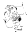
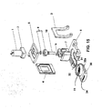
- pod-holding devices for beverage dispensing machines denoted overall by the reference number 100 are shown.
- Figures 1 to 5 show the pod-holding device according to the present invention which comprises a top motor 1 advantageously associated with a reducer 2 supported by a pair of shaped support plates 3 and 4 connecting together a top plate 5 and a bottom plate 6.
- the support plates 3 and 4 are spaced from each other and may for example have shaped through-recesses respectively in the form of an overturned "U” in the case of the plate 3 and a closed rectangle in the case of the plate 4.
- the support plates 3 and 4 are replaced by rods or support members for the top plate 5 and bottom plate 6.
- the operational components which are operated by the top motor 1 and by the reducer 2 of the pod-holding device are arranged between the plates or support members 3 and 4 and comprise overall a top filter head or unit 7, a nut 9 and a support 8 for a transmission screw 10.
- a bottom filter unit 11 is supported by the bottom plate 6 and aligned with the top filter unit 7.
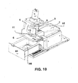
- the bottom filter unit 11 is designed to rotate about a horizontal axis preferably through an angle of about 90 degrees or less, and even more preferably through an angle of about 20°-65°, operated by a second motor unit or bottom motor 12 having preferably an axis perpendicular to that of the top motor 1.
- the bottom motor 12 is for example housed inside a space in the plate 6 so as to be coplanar therewith and transfer simply the rotational movement to the bottom filter unit 11.
- the top filter unit 7, the transmission screw 10, the nut 9, the support 8 and a safety element 13 form a block "A" consisting of parts moved vertically by the motor 1 and by the reduction gear 2 during dispensing of the beverage.
- the bottom filter unit 11 and bottom motor 12 form a block "B" and form the expulsion system, in which the bottom filter unit 11 is vertically fixed but rotatable about a horizontal axis.
- a safety element 13 is envisaged and is used during the downward movement of block A for formation of the beverage together with detection systems which check for the presence of any obstacles between the parts of the top block A and the parts of the bottom block B and interrupt the dispensing cycle described below.
- the top motor 1 is designed to move the system until it encloses a pod 66 arranged between the top filter unit 7 and the bottom filter unit 11, while the bottom motor 12 is intended to perform rotation of the bottom filter 11 so as to expel the used pod with a "catapulting" action.
- a pod 66 arranged between the top filter unit 7 and the bottom filter unit 11
- the bottom motor 12 is intended to perform rotation of the bottom filter 11 so as to expel the used pod with a "catapulting" action.
- the pod-holding device 100 is shown positioned inside a machine for dispensing beverages, for example made from coffee or tea, with the plates 5 and 6 arranged inclined relative to the horizontal bottom plane of the machine.
- the machine may be provided with a water container 41 provided with a closing cap 42 and connected to a heater 43 via connections known per se (not shown).
- the heater 43 supplies hot water to the top filter unit 7 via the connection means known per se (not shown). Operation of the machine containing the pod-holder is managed by a microcontroller using suitable control firmware.
- the top motor 1 is activated such that, via the reducer 2, it operates the transmission screw 10, being mechanically coupled to the latter via coupling means known per se.
- the transmission screw 10, advancing along the threaded nut 9, with its movement causes the movement also of the top filter unit 7.
- the top motor 1 is stopped and consequently all the parts which were in movement are stopped, so as to perform closing of the extraction chamber assisted by a sealing element of the circular O-ring type.
- the pod-holder is sealed so that it is possible to start dispensing of the beverage; the hot water enters into the top filter unit 7 via a suitable union (not shown), passes through the pod and flows out as a beverage from the outlet opening 14 of the bottom filter unit 11. Dispensing ends once the quantity prechosen for that given function has flowed out.
- top motor 1 is activated again and, with a reverse motion, returns to the previous top position, which may be located by means of an encoder, position microswitch, torque detection system or equivalent systems.
- the following step consists in expulsion towards the receiving drawer of the pod used for dispensing.
- the operation is performed by activating the bottom motor 12 which is mechanically connected to a reduction system a directly via its shaft to the bottom filter unit 11, first in one direction and immediately thereafter in the other direction.
- This movement generates a rotation which simulates a "catapulting" action, favouring removal of the pod towards the receiving drawer 61.
- this movement may be further controlled by means of an encoder, position microswitch, torque detection system or equivalent systems.
- the rotational movement is illustrated in detail in Figures 6 to 11 .
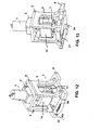
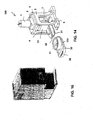
- Figures 12 to 16 show a simplified embodiment of the present invention in which the bottom plate 6 of the block B is without the bottom motor 12 and the bottom filter unit 11 is housed inside a drawer 30 which slides inside the associated sliding seat 31 formed in the bottom plate 6.
- the drawer 30 may be extracted fully from the pod-holding device by applying to the outer end of the drawer 30 a light pulling force, substantially at right angles to the front part of the beverage dispensing machine, so to cause sliding of the specially provided reliefs 32a inside the guides 32 formed in the bottom plate 6.
- the bottom filter unit 11 housed inside the drawer 30 has a suitable - preferably circular - shape such as to house the pod both during dispensing of the beverage and during extraction of the used pod.
- the drawer 30 is made to slide along the guides 32 to the end-of-travel position where the bottom filter unit 11 and top filter unit 7 are precisely aligned.
- the form of the filter unit 11 may be adapted to the form of the various types of pods produced by the manufacturers of coffee or tea or other types of beverages.
- the pod-holding device according to the present invention is particularly suitable for receiving pods with a preferably circular base and substantially flat form, with a thickness of about 1 cm, with or without either an aluminium or paper tongue.
- the pods may also be of the piercible type and in this case the top filter unit 7 and/or bottom filter unit 11 will be advantageously provided with piercing systems which are known per se.
- the drawer 30 has a projection 34 with a suitable shape so as to facilitate opening of the drawer 30 with the fingers or using any other suitable means.
- the top motor 1 is activated such that, via the reducer 2, it operates the transmission screw 10, being mechanically coupled to the latter via coupling means known per se.
- the transmission screw 10, advancing along the nut 9, with its movement causes the movement also of the top filter unit 7.
- the top motor 1 is stopped and consequently all the parts which were in movement are stopped, so as to perform closing of the extraction chamber.
- the pod-holder is sealed so that it is possible to start dispensing of the beverage; the hot water enters into the top filter unit 7 via a suitable union (not shown), passes through the pod and flows out as a beverage from the outlet opening 14 of the bottom filter unit 11. Dispensing ends once the quantity prechosen for that given function has flowed out.
- top motor 1 is activated again and, with a reverse motion, returns to the previous top position, which may be located by means of an encoder, position microswitch, torque detection system or equivalent systems.
- the following step consists in removal of the pod used for dispensing. This operation is performed by simply pulling manually the drawer 30 towards the user.
- the top filter unit 7, the worm screw 10, the nut 9, the support 8 and the safety element 13 form a block "A" consisting of parts moved vertically by the motor 1 and by the reduction gear 2 during formation of the beverage.
- the bottom filter unit 11 with the drawer 30 forms a block "B" and forms the expulsion system.
- the safety element 13 is used, during the downward movement of block "A” and together with detection systems such as microswitches or suitable equivalent systems, to check the presence of an obstacle between the top parts of block A and the bottom parts of block B and, if necessary, interrupt the dispensing cycle.
- the pod-holding device 100 may be made of metal, such as aluminium or an alimentary plastic suitable for withstanding the temperatures reached during operation of the machine.
- the electronic boards and the software designed to manage the operation of beverage dispensing machines are within the competence of a person skilled in the art.
- the pod-holder according to the invention owing to its constructional simplicity, allows the use of a firmware for managing simply the operations of the machine. Owing to the presence of firmware it is possible to modify in a simple manner management of the pod-holder and the machine in general.
- firmware results in flexibility with regard to control operations, functional features and any implementation of other features which are to be added subsequently.
- the firmware is responsible for full process control necessary for performing the required function, following an initial check that there exist all the necessary conditions for remaining activated until completion of the cycle.
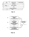
- Figure 17 shows the architecture of the firmware to be used in the beverage dispensing machine, which is organized in the four stratification levels shown in the diagram of the figure representing an example of analysis of the firmware.
- BOOT, INIT, APPLICATION and BOOTLOADER define (at least) 4 separate sessions (or levels) identified as run-levels:
- levels 1 and 2 will be carried out sequentially as from reset, followed by execution of run-level 3 on which actual operation of the machine depends, as summarised more clearly in the diagram shown in Figure 18 .
- Each run-level activates a set of process which, in a co-operative manner, are carried out following the rules defined during writing of the code.
- a simple events mechanism is the basic mechanism which ensures the synchronicity of the processes, the latter often being activated if specific events occur, such as the pressing of a button or the activation of a microswitch.
- Table 2 shows the non-limiting list of the services implemented in the firmware of the beverage dispensing machines provided with the pod-holder according to the present invention.
- the drivers provide access to the hardware or to specific structures of the firmware, displaying, at higher levels, a uniform interface which is as far as possible independent of the parameter being controlled.
- a driver often uses in turn the interfaces of other drivers; on other occasions the functionality of the driver is implemented in a service.
- the main drivers implemented in the beverage dispensing machines are, for example, shown in Table 3: Table 3 DRIVER/INTERFACE DESCRIPTION Com Interface for serial port transmission, reception and communication functions Timers Timing functions interface i2c Performs the functions for access to the interface I2C cmdline Analysis of the character flow received from com parser Divides the command line into syntactical elements (tokens) lexer Uses the structure ast (Abstract Syntax Tree) for lexical analysis of the token flow generated by the parser.
- adconverter Controls the functionality and access to and from the analog/digital converter inputs Provides access to the digital inputs of the machine filtered by the respective service motor Performs the motor control interface pump Performs the pump control interface heater Performs the heat exchanger control interface
- the HAL Hardware Abstraction Layer
- functions known to the person skilled in the art provides at higher levels access to the microcontroller resources such as the single input/output port.
- the description indicated explains its function and the term is known to persons skilled in the art.
- Run-level 3 implements all the functions intended for the beverage dispensing machine provided with the pod-holder according to the present invention during normal operation thereof.
- FSM finite-state machine
- Table 4 STATE DESCRIPTION STS_OFF The machine appears to the user to be switched off, but this state may be technically defined as STAND-BY.
- STS_INIT1 First initialization phase of the machine: the lamp test is performed and the head motor is activated, if necessary, so as to position the corresponding mechanical parts of the machine in the "home" position.
- STS_INIT2 Second initialization phase of the machine: the last part of the lamp test is performed and the pod expulsion motor is activated, if necessary, so as to bring the corresponding mechanical parts of the machine into the "home” position.
- STS_NOT_READY The machine is not warmed up; the drawer conditions, presence of water, etc., do not allow activation of any functions.
- STS_READY The machine is warmed up and is ready to activate the coffee and hot water functions; the drawer conditions, presence of water, etc, allow activation of the functions.
- STS_OPERATIVE The machine is performing a coffee or water function.
- STS_FAULT A technical problem has been detected.
- the diagram in Figure 19 shows the state transitions of the FSM.
- the advantage of using the firmware determines on the machine the possibility of adding or modifying the existing functions without intervention at the hardware level.
Landscapes
- Engineering & Computer Science (AREA)
- Food Science & Technology (AREA)
- Mechanical Engineering (AREA)
- Software Systems (AREA)
- General Engineering & Computer Science (AREA)
- Theoretical Computer Science (AREA)
- Computer Security & Cryptography (AREA)
- Physics & Mathematics (AREA)
- General Physics & Mathematics (AREA)
- Apparatus For Making Beverages (AREA)
- Filling Of Jars Or Cans And Processes For Cleaning And Sealing Jars (AREA)
- Manipulator (AREA)
Claims (7)
- Un dispositif de support pour dosette (100) pour machines de distribution de boissons, apte pour abriter des dosettes contenant une substance destinée à être extraite ou reconstituée par le passage d'eau et comprenant une première et une deuxième sous-unité d'extraction,- la première sous-unité d'extraction comprenant une demi-coque du haut abritant intérieurement une unité de filtre du haut (7) apte pour fermer de manière étanche contre une unité de filtre du bas (11) correspondante, de manière à former, lors de fermeture, une chambre d'extraction pour la dosette et à permettre, lors d'ouverture, l'insertion de ladite dosette entre les deux sous-unités, la première sous-unité étant mobile et comprenant une première unité de moteur (1), une vis de transmission (10) avec un support associé (8) et un écrou (9) connecté opérationnellement à la demi-coque du haut;- la deuxième sous-unité comprenant une demi-coque du bas contenant l'unité de filtre du bas (11) apte pour recevoir la dosette et l'expulser après extraction, le dit dispositif de support pour dosette étant caractérisé en ce que l'unité de moteur du haut (1) est supportée par une paire de plaques de support formées (3) et (4) connectant ensemble une plaque du haut (5) et une plaque du bas (6), à l'intérieur de laquelle un siège récepteur pour l'unité de filtre du bas (11) est formé.
- Le dispositif de support pour dosette selon la revendication 1, dans lequel la paire de plaques de support (3) et (4) sont remplacées par des membres de support ou tiges.
- Le dispositif de support pour dosette selon la revendication 1, dans lequel l'unité de filtre du haut (7) ou l'unité de filtre du bas (11) ou les deux sont pourvues d'un système de perçage de dosette.
- Le dispositif de support pour dosette selon les revendications 1 à 3, d'avantage pourvu d'un élément de sécurité (13).
- Le dispositif de support pour dosette selon les revendications 1 à 4, dans lequel la plaque du bas (6) abrite une deuxième unité de moteur (12), connectée opérationnellement à l'unité de filtre du bas (11) pour l'expulsion de la dosette et dans lequel l'unité de filtre du bas (11) a un axe qui permet la rotation de celle-ci, préférablement à travers un angle d'environ 90 degrés ou moins, ou plus préférablement à travers un angle d'environ 20° to 65°, étant opéré par la deuxième unité de moteur (12).
- Le dispositif de support pour dosette selon les revendications 1 à 4, dans lequel le siège récepteur dans la plaque du bas (6) est formé de manière à permettre le coulissage d'un tiroir extractible (30) abritant intérieurement l'unité de filtre du bas (11) qui coulisse dans le siège coulissant associé (31) formé dans la plaque du bas (6).
- Une machine de distribution de boissons comprenant le dispositif de support pour dosette selon les revendications 1 à 6.
Applications Claiming Priority (2)
| Application Number | Priority Date | Filing Date | Title |
|---|---|---|---|
| IT000458A ITRM20110458A1 (it) | 2011-09-05 | 2011-09-05 | Dispositivo porta-cialda per macchina erogatrice di bevande |
| PCT/IT2012/000269 WO2013035120A1 (fr) | 2011-09-05 | 2012-09-04 | Support pour dosette |
Publications (2)
| Publication Number | Publication Date |
|---|---|
| EP2763573A1 EP2763573A1 (fr) | 2014-08-13 |
| EP2763573B1 true EP2763573B1 (fr) | 2015-08-12 |
Family
ID=44899080
Family Applications (1)
| Application Number | Title | Priority Date | Filing Date |
|---|---|---|---|
| EP12773400.2A Active EP2763573B1 (fr) | 2011-09-05 | 2012-09-04 | Porte-dosette |
Country Status (6)
| Country | Link |
|---|---|
| US (1) | US10130208B2 (fr) |
| EP (1) | EP2763573B1 (fr) |
| CN (1) | CN103841860B (fr) |
| CA (1) | CA2846798A1 (fr) |
| IT (1) | ITRM20110458A1 (fr) |
| WO (1) | WO2013035120A1 (fr) |
Families Citing this family (4)
| Publication number | Priority date | Publication date | Assignee | Title |
|---|---|---|---|---|
| US20170119200A1 (en) * | 2016-01-19 | 2017-05-04 | Anthony David Bressi | Automated beverage and fragrance synthesizers |
| ITUA20162284A1 (it) * | 2016-04-04 | 2017-10-04 | Iacobucci Hf Aerospace S P A | Cappuccinatore |
| ITUA20164158A1 (it) * | 2016-06-07 | 2017-12-07 | Xlvi Operai Del Vapore S R L Unipersonale | Dispositivo a mensola per portafiltro per macchine da caffè espresso |
| USD982375S1 (en) | 2019-06-06 | 2023-04-04 | Sharkninja Operating Llc | Food preparation device |
Family Cites Families (36)
| Publication number | Priority date | Publication date | Assignee | Title |
|---|---|---|---|---|
| DE3607656A1 (de) * | 1986-03-08 | 1987-09-17 | Cafina Ag | Kolben-zylinder-aggregat fuer eine kaffeemaschine und verfahren zum betrieb |
| IT221582Z2 (it) * | 1991-01-25 | 1994-07-22 | Ricerca Elettromeccanica Srl | Apparecchio per la produzione di caffe' |
| US5134925A (en) * | 1991-04-10 | 1992-08-04 | Bunn-O-Matic Corporation | Automatic brewer |
| US5911810A (en) * | 1997-06-23 | 1999-06-15 | Sanden Corp. | Coffee brewing apparatus and method of brewing coffee by the apparatus |
| ITRM990017U1 (it) | 1999-02-01 | 2000-08-01 | Goodrich Co B F | Macchina per caffe' all'americana per impieghi aeronautici. |
| DK1153561T3 (da) * | 2000-05-09 | 2005-11-14 | Nestle Sa | Indretning til udtrækning af en substans |
| DE20105672U1 (de) | 2001-03-31 | 2001-09-13 | Eugster/Frismag Ag, Romanshorn | Espressobrüheinrichtung |
| ITRM20010098U1 (it) | 2001-05-16 | 2002-11-16 | Iacobucci S P A | Macchina erogatrice di caffe'. |
| CA2472653C (fr) * | 2002-03-01 | 2012-01-03 | Compagnie Mediterraneenne Des Cafes | Dispositif de production de boisson par infusion |
| US7237475B2 (en) * | 2003-12-23 | 2007-07-03 | Electrical And Electronics, Limited | Cabinet design of filter holder for pressurized espresso machines |
| US7617763B2 (en) * | 2003-12-23 | 2009-11-17 | Electrical & Electronics Limited | Motorized and remote-controlled cabinet design of filter holder for pressurized espresso machines |
| DE102004004314B4 (de) * | 2004-01-28 | 2014-05-15 | Tchibo Gmbh | Brühvorrichtung für eine Kaffeemaschine |
| CN1997585B (zh) * | 2004-02-13 | 2013-11-06 | 美商智高咖啡公司 | 具可更换浓缩/萃取匣的浓缩/萃取饮料分配器 |
| FR2873011B1 (fr) * | 2004-07-16 | 2007-12-14 | Reneka Internat Sarl | Groupe de preparation d'au moins une tasse de cafe de type expresso ou autre boisson chaude a partir d'une dose individuelle preemballee appelee dosette |
| PT1656863E (pt) * | 2004-11-11 | 2011-03-22 | Nestec Sa | Cabeça de mistura de limpeza automática para produção de uma mistura à base de leite e máquinas de produção de bebidas compreendendo esta cabeça de mistura |
| EP1676509A1 (fr) * | 2004-12-30 | 2006-07-05 | Rhea Vendors S.p.A. | Procédé et dispositif pour le contrôle de la préparation d'infusions |
| JP2008531162A (ja) * | 2005-02-28 | 2008-08-14 | コーヒー ネーション リミテッド | 飲料を製造する装置 |
| CA2627328C (fr) * | 2005-04-11 | 2014-06-17 | Coffee Equipment Company | Machine destinee a l'infusion de boissons telles que le cafe et procede associe |
| ATE537740T1 (de) * | 2005-04-22 | 2012-01-15 | Coffee Innovation Group B V | Kaffeezubereitungsvorrichtung |
| ITFI20050112A1 (it) * | 2005-05-27 | 2006-11-28 | Saeco Internat Group S P A | Dispositivo e metodo per la produzione di bevande, in specie caffe', da confezioni monodose |
| US7507430B2 (en) * | 2005-06-10 | 2009-03-24 | Concordia Coffee Company, Inc. | Method for preparing a heated flavored beverage |
| ES2317123T5 (es) * | 2005-09-27 | 2017-05-05 | Nestec S.A. | Módulo de extracción para un dispositivo de producción de bebidas a partir de cápsulas |
| DE602005012979D1 (de) * | 2005-12-23 | 2009-04-09 | Rancilio Macchine Caffe | Brühvorrichtung |
| ITLE20060009A1 (it) * | 2006-03-10 | 2006-06-09 | Giovanni Spinelli | Invenzione nel campo delle macchine da caffe' a fap/capsule |
| US7513192B2 (en) * | 2006-03-23 | 2009-04-07 | Keurig, Incorporated | Beverage forming device with opening/closing mechanism for a beverage cartridge receiver |
| ITFI20070028A1 (it) * | 2007-02-07 | 2008-08-08 | Saeco Ipr Ltd | Dispositivo di infusione per la preparazione di bevande da capsule monodose con un dispositivo di centraggio delle capsule. |
| US8490540B2 (en) * | 2007-05-16 | 2013-07-23 | Newco Enterprises, Inc. | Programmable brewer |
| GB2449213B (en) * | 2007-05-18 | 2011-06-29 | Kraft Foods R & D Inc | Improvements in or relating to beverage preparation machines and beverage cartridges |
| GB2463350B (en) * | 2007-05-18 | 2010-07-28 | Kraft Foods R & D Inc | Improvements in or relating to beverage preparation machines |
| RU2501512C2 (ru) * | 2008-03-14 | 2013-12-20 | Мокофе Аг | Устройство и капсула для приготовления напитка |
| CA2720031A1 (fr) * | 2008-04-28 | 2009-11-05 | Tata Tea Limited | Appareil automatique de brassage et de transport de capsules monodose destine a produire une boisson chaude fraichement brassee |
| EP2271239A4 (fr) * | 2008-04-28 | 2012-08-22 | Tata Global Beverages Ltd | Appareil de brassage automatique et de distribution de boisson chaude |
| DE202008015035U1 (de) * | 2008-11-13 | 2009-01-29 | SEVERIN ELEKTROGERÄTE GmbH | Vorrichtung zur Herstellung eines Brühgetränkes |
| AU2011223792B2 (en) * | 2010-03-01 | 2015-02-05 | Concordia Coffee Company, Inc. | Accelerated low pressure brewer |
| US8623441B2 (en) * | 2010-03-01 | 2014-01-07 | Concordia Coffee Company, Inc. | Method and apparatus for controlling brewed beverage quality |
| US8616116B2 (en) * | 2010-03-01 | 2013-12-31 | Concordia Coffee Company, Inc. | High speed brewing apparatus |
-
2011
- 2011-09-05 IT IT000458A patent/ITRM20110458A1/it unknown
-
2012
- 2012-09-04 EP EP12773400.2A patent/EP2763573B1/fr active Active
- 2012-09-04 CN CN201280048699.8A patent/CN103841860B/zh active Active
- 2012-09-04 CA CA2846798A patent/CA2846798A1/fr not_active Abandoned
- 2012-09-04 US US14/342,722 patent/US10130208B2/en active Active
- 2012-09-04 WO PCT/IT2012/000269 patent/WO2013035120A1/fr not_active Ceased
Also Published As
| Publication number | Publication date |
|---|---|
| CA2846798A1 (fr) | 2013-03-14 |
| CN103841860B (zh) | 2016-10-12 |
| US10130208B2 (en) | 2018-11-20 |
| US20140331217A1 (en) | 2014-11-06 |
| ITRM20110458A1 (it) | 2013-03-06 |
| CN103841860A (zh) | 2014-06-04 |
| WO2013035120A1 (fr) | 2013-03-14 |
| EP2763573A1 (fr) | 2014-08-13 |
Similar Documents
| Publication | Publication Date | Title |
|---|---|---|
| US10682004B2 (en) | Beverage machine with a cover for an ingredient inlet | |
| EP2906089B1 (fr) | Machine pour préparer des boissons | |
| EP2763573B1 (fr) | Porte-dosette | |
| JP2017140415A (ja) | 原材料入口用のカバーを有する飲料マシン | |
| EP3203884B1 (fr) | Machine de préparation de boisson reconfigurable | |
| EP3203883B1 (fr) | Unité d'extraction de machine de préparation de boisson | |
| CN107847075B (zh) | 具有单马达致动的饮料制备机器 |
Legal Events
| Date | Code | Title | Description |
|---|---|---|---|
| PUAI | Public reference made under article 153(3) epc to a published international application that has entered the european phase |
Free format text: ORIGINAL CODE: 0009012 |
|
| 17P | Request for examination filed |
Effective date: 20140304 |
|
| AK | Designated contracting states |
Kind code of ref document: A1 Designated state(s): AL AT BE BG CH CY CZ DE DK EE ES FI FR GB GR HR HU IE IS IT LI LT LU LV MC MK MT NL NO PL PT RO RS SE SI SK SM TR |
|
| DAX | Request for extension of the european patent (deleted) | ||
| RAP1 | Party data changed (applicant data changed or rights of an application transferred) |
Owner name: IACOBUCCI HF AEROSPACE S.P.A. |
|
| GRAP | Despatch of communication of intention to grant a patent |
Free format text: ORIGINAL CODE: EPIDOSNIGR1 |
|
| INTG | Intention to grant announced |
Effective date: 20150206 |
|
| GRAS | Grant fee paid |
Free format text: ORIGINAL CODE: EPIDOSNIGR3 |
|
| GRAA | (expected) grant |
Free format text: ORIGINAL CODE: 0009210 |
|
| RAP1 | Party data changed (applicant data changed or rights of an application transferred) |
Owner name: IACOBUCCI, LUCIO |
|
| RIN1 | Information on inventor provided before grant (corrected) |
Inventor name: IACOBUCCI, LUCIO |
|
| AK | Designated contracting states |
Kind code of ref document: B1 Designated state(s): AL AT BE BG CH CY CZ DE DK EE ES FI FR GB GR HR HU IE IS IT LI LT LU LV MC MK MT NL NO PL PT RO RS SE SI SK SM TR |
|
| REG | Reference to a national code |
Ref country code: GB Ref legal event code: FG4D |
|
| REG | Reference to a national code |
Ref country code: CH Ref legal event code: EP |
|
| REG | Reference to a national code |
Ref country code: AT Ref legal event code: REF Ref document number: 741353 Country of ref document: AT Kind code of ref document: T Effective date: 20150815 |
|
| REG | Reference to a national code |
Ref country code: IE Ref legal event code: FG4D |
|
| REG | Reference to a national code |
Ref country code: DE Ref legal event code: R096 Ref document number: 602012009650 Country of ref document: DE |
|
| REG | Reference to a national code |
Ref country code: LT Ref legal event code: MG4D |
|
| REG | Reference to a national code |
Ref country code: AT Ref legal event code: MK05 Ref document number: 741353 Country of ref document: AT Kind code of ref document: T Effective date: 20150812 |
|
| REG | Reference to a national code |
Ref country code: NL Ref legal event code: MP Effective date: 20150812 |
|
| PG25 | Lapsed in a contracting state [announced via postgrant information from national office to epo] |
Ref country code: LT Free format text: LAPSE BECAUSE OF FAILURE TO SUBMIT A TRANSLATION OF THE DESCRIPTION OR TO PAY THE FEE WITHIN THE PRESCRIBED TIME-LIMIT Effective date: 20150812 Ref country code: NO Free format text: LAPSE BECAUSE OF FAILURE TO SUBMIT A TRANSLATION OF THE DESCRIPTION OR TO PAY THE FEE WITHIN THE PRESCRIBED TIME-LIMIT Effective date: 20151112 Ref country code: FI Free format text: LAPSE BECAUSE OF FAILURE TO SUBMIT A TRANSLATION OF THE DESCRIPTION OR TO PAY THE FEE WITHIN THE PRESCRIBED TIME-LIMIT Effective date: 20150812 Ref country code: GR Free format text: LAPSE BECAUSE OF FAILURE TO SUBMIT A TRANSLATION OF THE DESCRIPTION OR TO PAY THE FEE WITHIN THE PRESCRIBED TIME-LIMIT Effective date: 20151113 Ref country code: LV Free format text: LAPSE BECAUSE OF FAILURE TO SUBMIT A TRANSLATION OF THE DESCRIPTION OR TO PAY THE FEE WITHIN THE PRESCRIBED TIME-LIMIT Effective date: 20150812 |
|
| PG25 | Lapsed in a contracting state [announced via postgrant information from national office to epo] |
Ref country code: ES Free format text: LAPSE BECAUSE OF FAILURE TO SUBMIT A TRANSLATION OF THE DESCRIPTION OR TO PAY THE FEE WITHIN THE PRESCRIBED TIME-LIMIT Effective date: 20150812 Ref country code: IS Free format text: LAPSE BECAUSE OF FAILURE TO SUBMIT A TRANSLATION OF THE DESCRIPTION OR TO PAY THE FEE WITHIN THE PRESCRIBED TIME-LIMIT Effective date: 20151212 Ref country code: PL Free format text: LAPSE BECAUSE OF FAILURE TO SUBMIT A TRANSLATION OF THE DESCRIPTION OR TO PAY THE FEE WITHIN THE PRESCRIBED TIME-LIMIT Effective date: 20150812 Ref country code: SE Free format text: LAPSE BECAUSE OF FAILURE TO SUBMIT A TRANSLATION OF THE DESCRIPTION OR TO PAY THE FEE WITHIN THE PRESCRIBED TIME-LIMIT Effective date: 20150812 Ref country code: RS Free format text: LAPSE BECAUSE OF FAILURE TO SUBMIT A TRANSLATION OF THE DESCRIPTION OR TO PAY THE FEE WITHIN THE PRESCRIBED TIME-LIMIT Effective date: 20150812 Ref country code: PT Free format text: LAPSE BECAUSE OF FAILURE TO SUBMIT A TRANSLATION OF THE DESCRIPTION OR TO PAY THE FEE WITHIN THE PRESCRIBED TIME-LIMIT Effective date: 20151214 Ref country code: HR Free format text: LAPSE BECAUSE OF FAILURE TO SUBMIT A TRANSLATION OF THE DESCRIPTION OR TO PAY THE FEE WITHIN THE PRESCRIBED TIME-LIMIT Effective date: 20150812 Ref country code: AT Free format text: LAPSE BECAUSE OF FAILURE TO SUBMIT A TRANSLATION OF THE DESCRIPTION OR TO PAY THE FEE WITHIN THE PRESCRIBED TIME-LIMIT Effective date: 20150812 |
|
| PG25 | Lapsed in a contracting state [announced via postgrant information from national office to epo] |
Ref country code: NL Free format text: LAPSE BECAUSE OF FAILURE TO SUBMIT A TRANSLATION OF THE DESCRIPTION OR TO PAY THE FEE WITHIN THE PRESCRIBED TIME-LIMIT Effective date: 20150812 |
|
| REG | Reference to a national code |
Ref country code: DE Ref legal event code: R119 Ref document number: 602012009650 Country of ref document: DE |
|
| PG25 | Lapsed in a contracting state [announced via postgrant information from national office to epo] |
Ref country code: EE Free format text: LAPSE BECAUSE OF FAILURE TO SUBMIT A TRANSLATION OF THE DESCRIPTION OR TO PAY THE FEE WITHIN THE PRESCRIBED TIME-LIMIT Effective date: 20150812 Ref country code: DK Free format text: LAPSE BECAUSE OF FAILURE TO SUBMIT A TRANSLATION OF THE DESCRIPTION OR TO PAY THE FEE WITHIN THE PRESCRIBED TIME-LIMIT Effective date: 20150812 Ref country code: SK Free format text: LAPSE BECAUSE OF FAILURE TO SUBMIT A TRANSLATION OF THE DESCRIPTION OR TO PAY THE FEE WITHIN THE PRESCRIBED TIME-LIMIT Effective date: 20150812 Ref country code: CZ Free format text: LAPSE BECAUSE OF FAILURE TO SUBMIT A TRANSLATION OF THE DESCRIPTION OR TO PAY THE FEE WITHIN THE PRESCRIBED TIME-LIMIT Effective date: 20150812 |
|
| REG | Reference to a national code |
Ref country code: CH Ref legal event code: PL |
|
| PG25 | Lapsed in a contracting state [announced via postgrant information from national office to epo] |
Ref country code: RO Free format text: LAPSE BECAUSE OF FAILURE TO SUBMIT A TRANSLATION OF THE DESCRIPTION OR TO PAY THE FEE WITHIN THE PRESCRIBED TIME-LIMIT Effective date: 20150812 Ref country code: MC Free format text: LAPSE BECAUSE OF FAILURE TO SUBMIT A TRANSLATION OF THE DESCRIPTION OR TO PAY THE FEE WITHIN THE PRESCRIBED TIME-LIMIT Effective date: 20150812 |
|
| PLBE | No opposition filed within time limit |
Free format text: ORIGINAL CODE: 0009261 |
|
| STAA | Information on the status of an ep patent application or granted ep patent |
Free format text: STATUS: NO OPPOSITION FILED WITHIN TIME LIMIT |
|
| REG | Reference to a national code |
Ref country code: IE Ref legal event code: MM4A |
|
| REG | Reference to a national code |
Ref country code: FR Ref legal event code: ST Effective date: 20160531 |
|
| 26N | No opposition filed |
Effective date: 20160513 |
|
| PG25 | Lapsed in a contracting state [announced via postgrant information from national office to epo] |
Ref country code: IE Free format text: LAPSE BECAUSE OF NON-PAYMENT OF DUE FEES Effective date: 20150904 Ref country code: LI Free format text: LAPSE BECAUSE OF NON-PAYMENT OF DUE FEES Effective date: 20150930 Ref country code: DE Free format text: LAPSE BECAUSE OF NON-PAYMENT OF DUE FEES Effective date: 20160401 Ref country code: CH Free format text: LAPSE BECAUSE OF NON-PAYMENT OF DUE FEES Effective date: 20150930 |
|
| PG25 | Lapsed in a contracting state [announced via postgrant information from national office to epo] |
Ref country code: FR Free format text: LAPSE BECAUSE OF NON-PAYMENT OF DUE FEES Effective date: 20151012 Ref country code: SI Free format text: LAPSE BECAUSE OF FAILURE TO SUBMIT A TRANSLATION OF THE DESCRIPTION OR TO PAY THE FEE WITHIN THE PRESCRIBED TIME-LIMIT Effective date: 20150812 |
|
| PG25 | Lapsed in a contracting state [announced via postgrant information from national office to epo] |
Ref country code: BE Free format text: LAPSE BECAUSE OF FAILURE TO SUBMIT A TRANSLATION OF THE DESCRIPTION OR TO PAY THE FEE WITHIN THE PRESCRIBED TIME-LIMIT Effective date: 20150812 |
|
| PG25 | Lapsed in a contracting state [announced via postgrant information from national office to epo] |
Ref country code: MT Free format text: LAPSE BECAUSE OF FAILURE TO SUBMIT A TRANSLATION OF THE DESCRIPTION OR TO PAY THE FEE WITHIN THE PRESCRIBED TIME-LIMIT Effective date: 20150812 |
|
| GBPC | Gb: european patent ceased through non-payment of renewal fee |
Effective date: 20160904 |
|
| PG25 | Lapsed in a contracting state [announced via postgrant information from national office to epo] |
Ref country code: SM Free format text: LAPSE BECAUSE OF FAILURE TO SUBMIT A TRANSLATION OF THE DESCRIPTION OR TO PAY THE FEE WITHIN THE PRESCRIBED TIME-LIMIT Effective date: 20150812 Ref country code: BG Free format text: LAPSE BECAUSE OF FAILURE TO SUBMIT A TRANSLATION OF THE DESCRIPTION OR TO PAY THE FEE WITHIN THE PRESCRIBED TIME-LIMIT Effective date: 20150812 Ref country code: HU Free format text: LAPSE BECAUSE OF FAILURE TO SUBMIT A TRANSLATION OF THE DESCRIPTION OR TO PAY THE FEE WITHIN THE PRESCRIBED TIME-LIMIT; INVALID AB INITIO Effective date: 20120904 |
|
| PG25 | Lapsed in a contracting state [announced via postgrant information from national office to epo] |
Ref country code: CY Free format text: LAPSE BECAUSE OF FAILURE TO SUBMIT A TRANSLATION OF THE DESCRIPTION OR TO PAY THE FEE WITHIN THE PRESCRIBED TIME-LIMIT Effective date: 20150812 |
|
| PG25 | Lapsed in a contracting state [announced via postgrant information from national office to epo] |
Ref country code: GB Free format text: LAPSE BECAUSE OF NON-PAYMENT OF DUE FEES Effective date: 20160904 |
|
| PG25 | Lapsed in a contracting state [announced via postgrant information from national office to epo] |
Ref country code: LU Free format text: LAPSE BECAUSE OF NON-PAYMENT OF DUE FEES Effective date: 20150904 |
|
| PG25 | Lapsed in a contracting state [announced via postgrant information from national office to epo] |
Ref country code: MK Free format text: LAPSE BECAUSE OF FAILURE TO SUBMIT A TRANSLATION OF THE DESCRIPTION OR TO PAY THE FEE WITHIN THE PRESCRIBED TIME-LIMIT Effective date: 20150812 Ref country code: TR Free format text: LAPSE BECAUSE OF FAILURE TO SUBMIT A TRANSLATION OF THE DESCRIPTION OR TO PAY THE FEE WITHIN THE PRESCRIBED TIME-LIMIT Effective date: 20150812 |
|
| PG25 | Lapsed in a contracting state [announced via postgrant information from national office to epo] |
Ref country code: AL Free format text: LAPSE BECAUSE OF FAILURE TO SUBMIT A TRANSLATION OF THE DESCRIPTION OR TO PAY THE FEE WITHIN THE PRESCRIBED TIME-LIMIT Effective date: 20150812 |
|
| P01 | Opt-out of the competence of the unified patent court (upc) registered |
Effective date: 20230613 |
|
| PGFP | Annual fee paid to national office [announced via postgrant information from national office to epo] |
Ref country code: IT Payment date: 20250924 Year of fee payment: 14 |