EP2763733B1 - Outil de positionnement de fil-guide - Google Patents
Outil de positionnement de fil-guide Download PDFInfo
- Publication number
- EP2763733B1 EP2763733B1 EP12838434.4A EP12838434A EP2763733B1 EP 2763733 B1 EP2763733 B1 EP 2763733B1 EP 12838434 A EP12838434 A EP 12838434A EP 2763733 B1 EP2763733 B1 EP 2763733B1
- Authority
- EP
- European Patent Office
- Prior art keywords
- sheath
- retainer
- collet
- guidewire
- positioning tool
- Prior art date
- Legal status (The legal status is an assumption and is not a legal conclusion. Google has not performed a legal analysis and makes no representation as to the accuracy of the status listed.)
- Not-in-force
Links
- 239000012530 fluid Substances 0.000 claims description 15
- 238000004891 communication Methods 0.000 claims description 9
- 230000007246 mechanism Effects 0.000 claims description 6
- 230000000007 visual effect Effects 0.000 claims description 6
- 230000008859 change Effects 0.000 claims description 4
- 239000003550 marker Substances 0.000 claims description 4
- 210000005166 vasculature Anatomy 0.000 description 10
- 229910052782 aluminium Inorganic materials 0.000 description 2
- XAGFODPZIPBFFR-UHFFFAOYSA-N aluminium Chemical compound [Al] XAGFODPZIPBFFR-UHFFFAOYSA-N 0.000 description 2
- 230000003466 anti-cipated effect Effects 0.000 description 2
- 230000002596 correlated effect Effects 0.000 description 2
- 239000000314 lubricant Substances 0.000 description 2
- 229910052751 metal Inorganic materials 0.000 description 2
- 239000002184 metal Substances 0.000 description 2
- 238000000034 method Methods 0.000 description 2
- 239000004033 plastic Substances 0.000 description 2
- 229920003023 plastic Polymers 0.000 description 2
- 229910001220 stainless steel Inorganic materials 0.000 description 2
- 239000010935 stainless steel Substances 0.000 description 2
- 229910001369 Brass Inorganic materials 0.000 description 1
- 239000004793 Polystyrene Substances 0.000 description 1
- 229920006397 acrylic thermoplastic Polymers 0.000 description 1
- 230000009471 action Effects 0.000 description 1
- 239000000853 adhesive Substances 0.000 description 1
- 230000001070 adhesive effect Effects 0.000 description 1
- 229910045601 alloy Inorganic materials 0.000 description 1
- 239000000956 alloy Substances 0.000 description 1
- 238000013459 approach Methods 0.000 description 1
- 239000010951 brass Substances 0.000 description 1
- 230000006835 compression Effects 0.000 description 1
- 238000007906 compression Methods 0.000 description 1
- 230000000875 corresponding effect Effects 0.000 description 1
- 230000007423 decrease Effects 0.000 description 1
- 238000013461 design Methods 0.000 description 1
- 238000006073 displacement reaction Methods 0.000 description 1
- 238000005516 engineering process Methods 0.000 description 1
- -1 for example Polymers 0.000 description 1
- 238000003780 insertion Methods 0.000 description 1
- 230000037431 insertion Effects 0.000 description 1
- 230000001926 lymphatic effect Effects 0.000 description 1
- 230000014759 maintenance of location Effects 0.000 description 1
- 150000002739 metals Chemical class 0.000 description 1
- 239000000203 mixture Substances 0.000 description 1
- 229920003229 poly(methyl methacrylate) Polymers 0.000 description 1
- 239000004417 polycarbonate Substances 0.000 description 1
- 229920000515 polycarbonate Polymers 0.000 description 1
- 229920002223 polystyrene Polymers 0.000 description 1
- 239000004800 polyvinyl chloride Substances 0.000 description 1
- 229920000915 polyvinyl chloride Polymers 0.000 description 1
- 230000008569 process Effects 0.000 description 1
- ISXSCDLOGDJUNJ-UHFFFAOYSA-N tert-butyl prop-2-enoate Chemical compound CC(C)(C)OC(=O)C=C ISXSCDLOGDJUNJ-UHFFFAOYSA-N 0.000 description 1
- 230000007704 transition Effects 0.000 description 1
- 238000003466 welding Methods 0.000 description 1
Images


Classifications
-
- A—HUMAN NECESSITIES
- A61—MEDICAL OR VETERINARY SCIENCE; HYGIENE
- A61M—DEVICES FOR INTRODUCING MEDIA INTO, OR ONTO, THE BODY; DEVICES FOR TRANSDUCING BODY MEDIA OR FOR TAKING MEDIA FROM THE BODY; DEVICES FOR PRODUCING OR ENDING SLEEP OR STUPOR
- A61M25/00—Catheters; Hollow probes
- A61M25/01—Introducing, guiding, advancing, emplacing or holding catheters
- A61M25/09—Guide wires
- A61M25/09041—Mechanisms for insertion of guide wires
-
- A—HUMAN NECESSITIES
- A61—MEDICAL OR VETERINARY SCIENCE; HYGIENE
- A61B—DIAGNOSIS; SURGERY; IDENTIFICATION
- A61B17/00—Surgical instruments, devices or methods
- A61B2017/0046—Surgical instruments, devices or methods with a releasable handle; with handle and operating part separable
- A61B2017/00469—Surgical instruments, devices or methods with a releasable handle; with handle and operating part separable for insertion of instruments, e.g. guide wire, optical fibre
-
- A—HUMAN NECESSITIES
- A61—MEDICAL OR VETERINARY SCIENCE; HYGIENE
- A61M—DEVICES FOR INTRODUCING MEDIA INTO, OR ONTO, THE BODY; DEVICES FOR TRANSDUCING BODY MEDIA OR FOR TAKING MEDIA FROM THE BODY; DEVICES FOR PRODUCING OR ENDING SLEEP OR STUPOR
- A61M25/00—Catheters; Hollow probes
- A61M25/01—Introducing, guiding, advancing, emplacing or holding catheters
- A61M25/09—Guide wires
- A61M2025/09116—Design of handles or shafts or gripping surfaces thereof for manipulating guide wires
Definitions
- Medical guidewires are devices that may be used to assist in the positioning of catheters, stents, and other medical devices in the circulatory, lymphatic, and other systems.
- a user will insert the guidewire percutaneously, and proceed to feed the guidewire through the vasculature system.
- the user may navigate the guidewire through branches in the vasculature.
- a catheter, stent, or other device may be advanced over the path defined by the guidewire and subsequently placed at the desired location.
- the width of a guidewire is generally correlated with the width of the vasculature system of intended use. For example, diameters from 0.010" (0.254mm) to 0.038" (0.9652mm) are common guidewire sizes in the medical field.
- the length of a guidewire may be limited by the type of procedure and/or the desired location within the vasculature. Lengths ranging from 50 cm to 450 cm are common. As a result, guidewires are often long and slender and it depends upon the skill of a particular user to manipulate and advance the guidewire in use.
- a guidewire positioning tool is known from US 5 161 534 A , It only comprises a body and a collet each having a longitudinally extending slot and a bore as well as a nut which may be threaded onto the collet and which also includes a longitudinal slot which is alignable with the slot in the body and collet to receive a guide wire.
- Further positioning tools having a body and a collet or another part each having a longitudinal slot for receiving a guide wire and which are rotatable with regard to each other are known from WO 2007/082 216 A1 , US 2004/162 465 A1 , US 2002/072 712 A1 and US 2005/240 120 A1 .
- a guidewire positioning tool as claimed in claim 1 includes a sheath having a bore extending axially through a length of the sheath.
- the bore has a slot extending radially from the bore.
- the bore and the slot are configured to receive a guidewire.
- a collet portion extends distally from a distal end of the sheath.
- the collet has collet arms and interstitial spaces.
- a bore extends axially through a length of the collet portion.
- the bore has a slot extending radially from the bore.
- the bore and the slot are configured to receive a guidewire.
- the collet arms have threads located on the exterior of the collet arms.
- a clamp nut is positioned over the collet portion and configured to threadably engage the threads, wherein the clamp nut comprises a slot.
- a retainer is rotatably attached to a proximal end of the sheath.
- the retainer has a bore extending axially through a length of the retainer.
- the bore has a slot extending radially from the bore. The bore and the slot are configured to receive a guidewire.
- the sheath may include a radially positioned aperture to allow for fluid communication between the exterior of the sheath and the bore of the sheath.
- the retainer may include a pocket for receiving fluid. In an embodiment where both are present, the aperture and the pocket may be aligned for fluid communication when in an open position, with the aperture and the pocket not aligned for fluid communication when in a locked position.
- one of the retainer and the sheath or collet includes a protrusion and the other of the retainer and the sheath or collet includes a recess.
- the protrusion and the recess cooperate to act as a tongue and groove arrangement to limit the movement of the retainer relative to the sheath when transitioning between a locked and an open position relative to the sheath.
- the protrusion and the recess cooperate to act as a detent mechanism to hold the retainer in one of a locked or open position relative to the sheath.
- the one of the protrusion and the recess included with the retainer may be formed upon an interior end of the retainer and the other of the protrusion and the recessed included with the sheath or collet may be formed on an interior portion of the sheath or collet.
- the clamp nut includes a visual indicator to indicate position of the clamp nut relative to the collet portion.
- the visual indicator may be a change in color about the circumference of the clamp nut.
- the visual indicator may be a marker on the exterior of the clamp nut. It is contemplated that the marker may align with the slot of the collet portion when in a locked position and not align with the slot of the collet portion when in an open position, although such is not required.
- one of the clamp nut and the sheath includes a protrusion and the other of the clamp nut and the sheath includes a recess where the protrusion and recess cooperate to act as a tongue and groove arrangement to limit the movement of the clamp nut relative to the sheath when transitioning between a locked and an open position relative to the sheath.
- one of the clamp nut and the sheath includes a protrusion and the other of the clamp nut and the sheath includes a recess where the protrusion and the recess cooperate to act as a detent mechanism to hold the clamp nut in one of a locked or open position relative to the sheath.
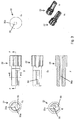
- FIG 1 a guidewire positioning tool that has a body 20 with a retainer 22 and a collet 24.
- the body 20 has a proximal end 26 and a distal end 28.
- the body 20 is generally cylindrically shaped, although the body may be shaped otherwise.
- the body 20 includes a sheath 44 which has a bore 30 extending axially through its length. Extending radially from the bore 30 is a slot 32 configured to receive a guidewire. The slot 32 extends laterally along the entire length of the sheath 44.
- the retainer 22 has a bore 30a extending axially through its length. Extending radially from the bore 30a is a slot 32a configured to receive a guidewire. As illustrated, the bore 30a and the slot 32a are sized similarly to the bore 30 and slot 32 of the sheath 44, although such is not required. In at least one embodiment, the retainer 22 is configured for limited rotation, such as 60, 90, or 120 degrees or any other desired amount, relative to the sheath 44. Alternatively, the retainer 22 may be configured to rotate freely about the sheath 44. In an unlocked, or open, position, the slot 32a is aligned with the slot 32 to facilitate placement of the guidewire positioning tool on a guidewire longitudinally. In a closed, or locked, position, the retainer 22 is rotated such that the slot 32a is unaligned with the slot 32 and thus prevents displacement of the guidewire positioning tool and an associated guidewire in a longitudinal fashion.
- the retainer 22 may include a pocket 50 for the placement and/or retention of fluid, such as fluid used to lubricate
- fluid such as fluid used to lubricate
- the fluid may be placed in the pocket 50 before the assembly of the body 20 or after assembly as will be further described below.
- the collet 24 has a bore 30b extending axially along its length. Extending radially from the bore 30b is a slot 32b that is configured to receive a guidewire.
- the bore 30b and the slot 32b are sized similarly to the bores 30 and 30a and to the slots 32 and 32a of the sheath 44 and retainer 22, respectively, although such is not required.
- the collet 24 is includes a number collet arms 34, such as two, three, four, or more or any suitable number. Between the collet arms 34 is an interstitial space 36. Interstitial spaces 36 are preferably narrower proximal to the sheath 44 than they are distal to the sheath 44. One of the interstitial spaces 36 may be the slot 32b, configured to receive a guidewire. However, the remaining interstitial spaces 36 may not necessarily be similarly sized. The portion of the collet arms 34 exterior to the bore 30b feature threads 38. Distal from the sheath 44, the collet 24 has a cap 40.
- the collet 24 may be formed from a portion of upper collet arms joined with a portion lower collet arms including the cap 40.
- a clamp nut 42 is disposed on the collet 24 and configured to engage the threads 38.
- the clamp nut 42 also has a slot 32c.
- the clamp nut In the unlocked, or open, position, the clamp nut is positioned on the collet 24 proximal to the sheath 44, and with its slot 32c aligned with the slot 32.
- the clamp nut 42 In one embodiment, in the closed, or locked, position, the clamp nut 42 is positioned on the collet 24 proximal to the cap 40, and with its slot 32c unaligned with the slot 32.
- the helical pitch of the threads 38 limits the rotation of the clamp nut 42 to one half turn, or 180°, about the collet 24. In other embodiments, the helical pitch of the threads 38 may limit the rotation of the clamp nut 42 to one quarter turn, or 90°, about the collet 24. In still other embodiments, the helical pitch of the threads 38 may limit the rotation of the clamp nut 42 to one full turn, or 360°, about the collet 24. Finally, in still other embodiments, the helical pitch of the threads 38 may limit the rotation of the clamp nut 42 to two or more full turns or any other desired amount.
- rotation of the clamp nut 42 may cease where the collet 24 abuts the cap 40, thus using the cap 40 as stop, although such is not required.
- rotation of the clamp nut 42 may cease at any desired point along the collet 24, for example due to change in diameter of the collet 24.
- the helical pitch of the threads 38 may correspond to the anticipated size of the guidewire. In some embodiments, the helical pitch will be small to accommodate a small guidewire. In other embodiments, the helical pitch will be large to accommodate a large guidewire. Finally, in still other embodiments, the helical pitch may not be correlated to the anticipated size of the guidewire.
- the threads 38 may have a right-handed pitch in some embodiments and a left-handed pitch in others.
- the relative position of the clamp nut 42 may provide an easy visualized locked and unlocked indicator.
- the clamp nut 42 may be a different color than the sheath 44 or the cap 40 to further make the locked and unlocked indications easy to visualize. Further, the color of the clamp nut 42 may vary about the circumference of the clamp nut 42 such that the color relative to a relatively stationary place on the body 20, such at the slot 30 of the sheath 44 or the slot of the cap 40, may indicate the position of the clamp nut 42.
- the clamp nut 42 may include recess 52 and the sheath 44 may include a protrusion 54, or vice versa.
- the protrusion 54 and the recess 52 cooperate to act as a detent mechanism to hold the clamp nut in one of a locked or open position relative to the sheath.
- the protrusion 54 and the recess 52 may be formed to cooperate to act as a tongue and groove arrangement to limit the movement of the clamp nut relative to the sheath when transitioning between a locked and an open position relative to the sheath.
- the body 20 includes the sheath 44 which defines a bore 30 and has the slot 32. At least a portion of the retainer 22 is disposed within the bore 30 with at least a portion of the bore 30a being coincident to the bore 30.
- retainer 22 In the unlocked, or open, position, retainer 22 is positioned within the sheath 44 such that slot 32a is aligned with slot 32.
- retainer 22 In the closed, or locked, position, retainer 22 is positioned within the sheath 44 such that slot 32a is unaligned with slot 32.
- the sheath 44 may include a radially positioned aperture 56 to allow for fluid communication between the exterior of the sheath 44 and the bore 30 of the sheath.
- an operator may provide, for example, additional lubricant to a guidewire inside the sheath 44.
- the aperture 56 and the pocket 50 may aligned for fluid communication when in an open position such that fluid, such as a guidewire lubricant, may be placed in the pocket 50 without having to disassemble the body 20. Then the aperture 56 and the pocket 50 may be not aligned for fluid communication when in a locked position.
- the guidewire positioning tool may be comprised of four parts.
- the sheath 44 and the collet 24 may be machined from one part, see FIGS. 4a, 4b, 4c, and 4d .
- the diameter of the collet 24 is smaller than the diameter of the sheath 44.
- the clamp nut 42 may be created separately from the sheath 44 and the collet 24, and placed over the collet 24.
- the clamp nut 42 is designed to engage the threads 38 and rotate around the collet 24.
- the clamp nut 42 is rotatable around the collet 24 and, in the illustrated embodiments, the rotation of the clamp nut 42 is stopped by the cap 40.
- the diameter of the clamp nut 42 is necessarily greater than the diameter of the collet 24, and preferably equal to or approximating the diameter of the sheath 44.
- the cap 40 may be comprised of a separate part.
- the cap 40 may then be attached to the collet 24.
- the cap 40 may be attached to the collet 24 by an adhesive.
- the cap 40 may be attached to the collet 24 by butt welding.
- the cap 40 may be frictionally fit to the collet 24.
- the diameter of the cap 40 may be equal to or approximating the diameter of the sheath 44. In alternate embodiments of the guidewire positioning tool, the cap 40 may be optionally excluded.
- the retainer 22 may be comprised of yet another separate part and attached to sheath 44. In one embodiment, the retainer 22 is frictionally fit to the sheath 44. The diameter of the retainer 22 may be equal to or approximating the diameter of the sheath 44.
- the diameter of the retainer 22 is designed to closely fit within the sheath 44, but still able to rotate within the sheath 44.
- the sheath 44 is sized to define the bore 30.
- the retainer 22 may have a protrusion or peg 45 extending from the end of the retainer 22 in the sheath 44 proximal the collet 24.
- the peg 45 may be configured to frictionally engage a recess or groove 25 in the sheath 44 or the collet 24.
- the size of the groove 25 will limit the rotational movement of the sheath 44 and the retainer 22. It must be understood that this arrangement may be reversed with the protrusion on the sheath 44 and the recess on the retainer 22.
- the guidewire positioning tool is designed to be approximately two inches long.
- the outside diameter of the tool may be between 0.250" - 0.3125" 0.635 - 0.794 cm.
- the diameter of the bore 30 may be between 0.020" - 0.048" 0.051 - 0.122 cm, while the width of the slot 30 may be between 0.015" - 0.043" 0.038 - 0.109 cm.
- the guidewire positioning tool is designed to be single-use and may be comprised of a hard plastic, for example, polyvinylchloride, acrylics, polycarbonates, or polystyrenes.
- the guidewire positioning tool is designed to be reusable and may be comprised of a metal, for example, aluminum, stainless steel, or alloys of brass, aluminum, or stainless steel.
- the guidewire positioning tool may be comprised of a mixture of plastics and metals.
- surgeons will use the guidewire positioning tool.
- other medical practitioners may use the guidewire positioning tool as well.
- nurses and x-ray technicians may use the guidewire positioning tool.
- the guidewire positioning tool may be used by a range of medical professionals and other users.
- the guidewire positioning tool is designed to facilitate the insertion of a guidewire into patient vasculature.
- a surgeon may mount the guidewire positioning tool laterally onto a guidewire, and may remove the guidewire positioning tool from the guidewire laterally.
- a surgeon may easily use two or more guidewire positioning tools during the catheterization process if so desired.
- a surgeon may mount the guidewire positioning tool longitudinally onto a guidewire and may remove the guidewire positioning tool from the guidewire longitudinally.
- the guidewire positioning tool may be oriented in the opposite direction without departing from the spirit of the invention.
- a surgeon will insert a guidewire percutaneously into a patient. The surgeon will then proceed to mount the guidewire positioning tool onto the guidewire. The surgeon will proceed to manipulate retainer 22 from the unlocked, or open, position to the closed, or locked, position to lock the guidewire within the guidewire positioning tool. In embodiments of the guidewire positioning tool which include sheath 44, movement of retainer 22 also engages sheath 44 from the unlocked, or open, position to the locked, or closed, position and serves to further lock the guidewire within the guidewire positioning tool.
- the bore 30a of the retainer 22 is approximately "D" shaped, while the bore 30b of the collet 24 is approximately "U” shaped.
- the shape of bore 30a positions and centers the guidewire proximal to the portion of the bores 30a and 30b distal from the slots 32a and 32b.
- the surgeon will then proceed to feed the guidewire through the guidewire positioning tool, specifically through the bore 30 and the corresponding bores 30a and 30b.
- the guidewire may fit loosely within bore 30.
- the surgeon will proceed to feed the guidewire through a patient's vasculature.
- the surgeon will then manipulate the collet 24 and the clamp nut 42 from the unlocked, or open, position to the locked, or closed, position.
- the clamp nut 42 engages the threads 38.
- the clamp nut 42 twists around the collet 24, it applies pressure to the collet arms 34.
- the amount of pressure applied to collet arms 34 increases, and the action of the clamp nut 42 causes the interstitial spaces 36 to compress. The compression of interstitial spaces 36 and the collet arms 34 decreases the diameter of bore 30b.
- the collet arms 34 are in tight frictional engagement with the guidewire.
- the rotation of the clamp nut 42 is limited by the diameter of the guidewire such that the collet arms 34 are in tight frictional engagement with the guidewire before the clamp nut 42 reaches the cap 40.
- the pressure asserted by the collet arms 34 assists the surgeon gripping and applying force to the guidewire so he may more easily navigate the branches within the vasculature.
- the collet 24 has three collet arms 34.
- the collet arm 34a is larger and slightly longer than the two approximately equally sized collet arms 34b. In the unlocked, or open, position, the collet arms 34b splay outward from the bore 30b.
- the cap 40 is only attached to the collet arm 34a. In this embodiment, when the clamp nut 42 rotates around the collet 24 towards the cap 40, the movement of the clamp nut 42 along the threads 38 serves to compress the collet arms 34b relative to the collet arm 34a.
- the surgeon When the surgeon has selected the branch of vasculature for use and manipulated an end of the guidewire into the branch, he may twist the clamp nut 42 from the closed position to the unlocked, or open, position. The surgeon then proceeds to continue feeding guidewire through the guidewire positioning tool.
- surgeon may use one hand to operate the guidewire positioning tool In an alternate embodiment, the surgeon will use two hands to operate the guidewire positioning tool.
Landscapes
- Health & Medical Sciences (AREA)
- Life Sciences & Earth Sciences (AREA)
- Biophysics (AREA)
- Pulmonology (AREA)
- Engineering & Computer Science (AREA)
- Anesthesiology (AREA)
- Biomedical Technology (AREA)
- Heart & Thoracic Surgery (AREA)
- Hematology (AREA)
- Animal Behavior & Ethology (AREA)
- General Health & Medical Sciences (AREA)
- Public Health (AREA)
- Veterinary Medicine (AREA)
- Media Introduction/Drainage Providing Device (AREA)
- Gripping On Spindles (AREA)
- Surgical Instruments (AREA)
Claims (15)
- Outil de positionnement de fil-guide, comportant :une gaine (44) dotée d'un alésage (30) s'étendant axialement sur une longueur de la gaine (44), l'alésage (30) présentant une fente (32) s'étendant radialement à partir de l'alésage (30), l'alésage (30) et la fente (32) étant configurés pour recevoir un fil-guide ; une partie (24) de mandrin s'étendant de façon distale à partir d'une extrémité distale de la gaine (44), le mandrin comprenant des bras (34) de mandrin et des espaces interstitiels (36), un alésage (30b) s'étendant axialement sur une longueur de la partie (24) de mandrin, l'alésage (30b) présentant une fente (32b) s'étendant radialement à partir de l'alésage (30b), l'alésage (30b) et la fente (32b) étant configurés pour recevoir un fil-guide, les bras (34) de mandrin étant dotés de filets (38) situés sur l'extérieur des bras (34) de mandrin ;un écrou (42) de serrage positionné par-dessus la partie (24) de mandrin et configuré pour coopérer par vissage avec les filets (38), l'écrou (42) de serrage comportant une fente (32c) ;caractérisé parun composant (22) de retenue rattaché de façon tournante à une extrémité proximale de la gaine (44), le composant (22) de retenue étant doté d'un alésage (30a) s'étendant axialement sur une longueur du composant (22) de retenue, l'alésage (30a) présentant une fente (32a) s'étendant radialement à partir de l'alésage (30a), l'alésage (30a) et la fente (32a) étant configurés pour recevoir un fil-guide.
- Outil de positionnement de fil-guide selon la revendication 1, la gaine (44) comprenant une ouverture (56) positionnée radialement pour permettre une communication fluidique entre l'extérieur de la gaine (44) et l'alésage (30) de la gaine (44).
- Outil de positionnement de fil-guide selon la revendication 1 ou 2, le composant (22) de retenue comprenant une poche (50) destinée à recevoir du fluide.
- Outil de positionnement de fil-guide selon la revendication 3, l'ouverture (56) et la poche (50) étant alignées en vue d'une communication fluidique dans une position ouverte et l'ouverture (56) et la poche (50) n'étant pas alignées en vue d'une communication fluidique dans une position verrouillée.
- Outil de positionnement de fil-guide selon la revendication 4, un élément parmi le composant (22) de retenue et la gaine (44) comprenant une protubérance (45) et l'autre élément parmi le composant (22) de retenue et la gaine (44) comprenant un évidement (25), la protubérance (45) et l'évidement (25) coopérant pour agir comme un dispositif à rainure et languette afin de limiter le mouvement du composant (22) de retenue par rapport à la gaine (44) lors d'une transition entre une position verrouillée et une position ouverte par rapport à la gaine (44).
- Outil de positionnement de fil-guide selon la revendication 1 ou 4, un élément parmi le composant (22) de retenue et la gaine (44) comprenant une protubérance (45) et l'autre élément parmi le composant (22) de retenue et la gaine (44) comprenant un évidement (25), la protubérance (45) et l'évidement (25) coopérant pour agir comme un mécanisme de cran afin de maintenir le composant (22) de retenue dans une des positions verrouillée et ouverte par rapport à la gaine (44), ou un élément parmi le composant (22) de retenue et le mandrin (24) comprenant une protubérance (45) et l'autre élément parmi le composant (22) de retenue et le mandrin (24) comprenant un évidement (25), la protubérance (45) et l'évidement (25) coopérant pour agir comme un mécanisme de cran afin de maintenir le composant (22) de retenue dans une des positions verrouillée et ouverte par rapport à la gaine (44).
- Outil de positionnement de fil-guide selon la revendication 1, l'écrou (42) de serrage comprenant un indicateur visuel pour indiquer la position de l'écrou (42) de serrage par rapport à la partie (24) de mandrin.
- Outil de positionnement de fil-guide selon la revendication 7, l'indicateur visuel étant un changement de couleur autour de la circonférence de l'écrou (42) de serrage.
- Outil de positionnement de fil-guide selon la revendication 7, l'indicateur visuel étant un repère sur l'extérieur de l'écrou (42) de serrage.
- Outil de positionnement de fil-guide selon la revendication 9, le repère s'alignant avec la fente (32b) de la partie (24) de mandrin dans une position verrouillée et ne s'alignant pas avec la fente (32b) de la partie (24) de mandrin dans une position ouverte.
- Outil de positionnement de fil-guide selon la revendication 1, un élément parmi le composant (22) de retenue et la gaine (44) comprenant une protubérance (45) et l'autre élément parmi le composant (22) de retenue et la gaine (44) comprenant un évidement (25), la protubérance (45) et l'évidement (25) coopérant pour agir comme un dispositif à rainure et languette afin de limiter le mouvement du composant (22) de retenue par rapport à la gaine (44) lors d'une transition entre une position verrouillée et une position ouverte par rapport à la gaine (44).
- Outil de positionnement de fil-guide selon la revendication 11, l'élément parmi la protubérance (45) et l'évidement (25) qui est incorporé avec le composant (22) de retenue étant formé sur une extrémité intérieure du composant (22) de retenue et l'autre élément parmi la protubérance (45) et l'évidement (25) qui est incorporé avec la gaine (44) étant formé sur une partie intérieure de la gaine (44).
- Outil de positionnement de fil-guide selon la revendication 11, l'élément parmi la protubérance (45) et l'évidement (25) qui est incorporé avec le composant (22) de retenue étant formé sur une extrémité intérieure du composant (22) de retenue et l'autre élément parmi la protubérance (45) et l'évidement (25) qui est incorporé avec le mandrin (24) étant formé sur une partie intérieure du mandrin (24).
- Outil de positionnement de fil-guide selon la revendication 1, un élément parmi l'écrou (42) de serrage et la gaine (44) comprenant une protubérance (54) et l'autre élément parmi l'écrou (42) de serrage et la gaine (44) comprenant un évidement (52), la protubérance (54) et l'évidement (52) coopérant pour agir comme un dispositif à rainure et languette afin de limiter le mouvement de l'écrou (42) de serrage par rapport à la gaine (44) lors d'une transition entre une position verrouillée et une position ouverte par rapport à la gaine (44).
- Outil de positionnement de fil-guide selon la revendication 1, un élément parmi l'écrou (42) de serrage et la gaine (44) comprenant une protubérance (54) et l'autre élément parmi l'écrou (42) de serrage et la gaine (44) comprenant un évidement (52), la protubérance (54) et l'évidement (52) coopérant pour agir comme un mécanisme de cran afin de maintenir l'écrou (42) de serrage dans une des positions verrouillée et ouverte par rapport à la gaine (44).
Applications Claiming Priority (3)
| Application Number | Priority Date | Filing Date | Title |
|---|---|---|---|
| US201161543641P | 2011-10-05 | 2011-10-05 | |
| US201261701950P | 2012-09-17 | 2012-09-17 | |
| PCT/US2012/059113 WO2013052906A2 (fr) | 2011-10-05 | 2012-10-05 | Outil de positionnement de fil-guide |
Publications (3)
| Publication Number | Publication Date |
|---|---|
| EP2763733A2 EP2763733A2 (fr) | 2014-08-13 |
| EP2763733A4 EP2763733A4 (fr) | 2015-08-05 |
| EP2763733B1 true EP2763733B1 (fr) | 2016-02-24 |
Family
ID=48044423
Family Applications (1)
| Application Number | Title | Priority Date | Filing Date |
|---|---|---|---|
| EP12838434.4A Not-in-force EP2763733B1 (fr) | 2011-10-05 | 2012-10-05 | Outil de positionnement de fil-guide |
Country Status (4)
| Country | Link |
|---|---|
| US (1) | US8986226B2 (fr) |
| EP (1) | EP2763733B1 (fr) |
| CN (1) | CN103998093B (fr) |
| WO (1) | WO2013052906A2 (fr) |
Families Citing this family (21)
| Publication number | Priority date | Publication date | Assignee | Title |
|---|---|---|---|---|
| US9078710B2 (en) * | 2012-12-12 | 2015-07-14 | Wright Medical Technology, Inc. | Orthopedic compression/distraction device |
| US9770272B2 (en) | 2012-12-12 | 2017-09-26 | Wright Medical Technology, Inc. | Orthopedic compression/distraction device |
| US9700703B2 (en) * | 2013-02-26 | 2017-07-11 | Coeur, Inc. | Guidewire insertion tool |
| US20160175564A1 (en) * | 2013-08-05 | 2016-06-23 | Vascular Imaging Corporation | Guidewire torque handle |
| CN104174109B (zh) * | 2014-09-02 | 2016-09-21 | 中国科学院自动化研究所 | 血管介入手术送丝装置的导丝支撑和夹持装置 |
| US20160101266A1 (en) * | 2014-10-09 | 2016-04-14 | Onanon, Inc. | Medical Instrument Clamp |
| US9770574B2 (en) * | 2014-10-22 | 2017-09-26 | Merit Medical Systems, Inc. | Torque device and securement mechanism |
| DE202015000456U1 (de) * | 2015-01-21 | 2016-04-22 | Urotech Gmbh | Vorrichtung zum Festklemmen eines medizinischen Führungsdrahtes |
| JP6998318B2 (ja) | 2016-03-30 | 2022-01-18 | コーニンクレッカ フィリップス エヌ ヴェ | 血管内装置を使用するためのトルク装置、及び関連するシステム、方法 |
| US10799686B2 (en) * | 2016-04-21 | 2020-10-13 | Johan Willem Pieter Marsman | Guidewire torquer |
| CN107376093B (zh) * | 2016-11-18 | 2024-07-19 | 苏州恒瑞迪生医疗科技有限公司 | 导丝扭控装置 |
| CN106823107A (zh) * | 2017-03-13 | 2017-06-13 | 周玉斌 | 一种快速交换的导丝扭控器 |
| CN108175923A (zh) * | 2017-11-23 | 2018-06-19 | 南通大学附属医院 | 一种辅助更换胃管的导丝及使用方法 |
| US11832995B2 (en) * | 2019-07-10 | 2023-12-05 | Vascular Technology, Incorporated | Graspable surgical device |
| USD952842S1 (en) | 2020-06-02 | 2022-05-24 | Bard Peripheral Vascular, Inc. | Ultrasonic catheter assembly |
| USD944395S1 (en) | 2020-06-02 | 2022-02-22 | Bard Peripheral Vascular, Inc. | Ultrasonic catheter handpiece with catheter |
| USD944396S1 (en) | 2020-06-02 | 2022-02-22 | Bard Peripheral Vascular, Inc. | Ultrasonic catheter handpiece housing |
| CN219501268U (zh) * | 2020-09-30 | 2023-08-11 | 爱德华兹生命科学公司 | 一种用于植入假体瓣膜的递送设备和一种组件 |
| CN117500556A (zh) * | 2021-05-19 | 2024-02-02 | 柯惠有限合伙公司 | 线材夹持装置 |
| CN118415723B (zh) * | 2024-06-20 | 2024-12-20 | 首都医科大学宣武医院 | 一种脑室腹腔分流管腹腔端置入装置 |
| CN119455230B (zh) * | 2024-11-18 | 2025-06-10 | 重庆大学 | 冠脉介入治疗用设备 |
Family Cites Families (15)
| Publication number | Priority date | Publication date | Assignee | Title |
|---|---|---|---|---|
| US5161534A (en) * | 1991-09-05 | 1992-11-10 | C. R. Bard, Inc. | Tool for manipulating a medical guidewire |
| US5312338A (en) * | 1992-11-30 | 1994-05-17 | Merit Medical Systems, Inc. | Rotation tool for medical guidewire |
| US6511470B1 (en) * | 1999-11-30 | 2003-01-28 | Scimed Life Systems, Inc. | Apparatus and method for steering a guidewire and connecting to an extension guidewire |
| US20020072712A1 (en) * | 2000-10-12 | 2002-06-13 | Nool Jeffrey A. | Medical wire introducer and protective sheath |
| US7959584B2 (en) | 2002-05-29 | 2011-06-14 | Boston Scientific Scimed, Inc. | Dedicated distal protection guidewires |
| US6893393B2 (en) | 2003-02-19 | 2005-05-17 | Boston Scientific Scimed., Inc. | Guidewire locking device and method |
| JP4579910B2 (ja) * | 2003-04-28 | 2010-11-10 | クック インコーポレイテッド | デュロメーターが変化する可撓性の挿入器シース |
| US20050240120A1 (en) * | 2004-04-26 | 2005-10-27 | Modesitt D B | Vise and method of use |
| WO2006124580A1 (fr) * | 2005-05-12 | 2006-11-23 | Wilson-Cook Medical, Inc. | Dispositif de couple pour passe-fil |
| JP2009522080A (ja) * | 2006-01-09 | 2009-06-11 | ウィンドクレスト リミテッド ライアビリティ カンパニー | 脈管ガイドワイヤコントロール装置 |
| CN101583318A (zh) | 2006-07-06 | 2009-11-18 | 安乔斯里德公司 | 收集鞘及其使用方法 |
| US7678648B2 (en) | 2006-07-14 | 2010-03-16 | Micron Technology, Inc. | Subresolution silicon features and methods for forming the same |
| JP2008149124A (ja) * | 2006-11-21 | 2008-07-03 | Nipro Corp | バルーンカバー |
| US7819844B2 (en) * | 2007-10-17 | 2010-10-26 | Gardia Medical Ltd. | Guidewire stop |
| US8372057B2 (en) | 2008-10-10 | 2013-02-12 | Coeur, Inc. | Luer lock adapter |
-
2012
- 2012-10-05 WO PCT/US2012/059113 patent/WO2013052906A2/fr not_active Ceased
- 2012-10-05 CN CN201280049438.8A patent/CN103998093B/zh not_active Expired - Fee Related
- 2012-10-05 EP EP12838434.4A patent/EP2763733B1/fr not_active Not-in-force
- 2012-10-05 US US13/646,436 patent/US8986226B2/en not_active Expired - Fee Related
Also Published As
| Publication number | Publication date |
|---|---|
| US20130190731A1 (en) | 2013-07-25 |
| CN103998093B (zh) | 2016-06-01 |
| EP2763733A2 (fr) | 2014-08-13 |
| WO2013052906A2 (fr) | 2013-04-11 |
| US8986226B2 (en) | 2015-03-24 |
| EP2763733A4 (fr) | 2015-08-05 |
| CN103998093A (zh) | 2014-08-20 |
| WO2013052906A3 (fr) | 2013-06-06 |
Similar Documents
| Publication | Publication Date | Title |
|---|---|---|
| EP2763733B1 (fr) | Outil de positionnement de fil-guide | |
| US12023224B2 (en) | Insertion system for deploying a ventilation device | |
| US20130103001A1 (en) | Side-Loading Torque Device | |
| US6533772B1 (en) | Guide wire torque device | |
| JP2023166626A (ja) | 脈管再入カテーテル | |
| US9814864B2 (en) | Torque apparatus for use with a guidewire | |
| US10363050B2 (en) | Variable diameter drill bit guide | |
| EP2110149B1 (fr) | Assemblage d'aiguille à ailettes et couvercle fragile | |
| JP6588678B2 (ja) | ダイレータ | |
| US7186224B2 (en) | Side attaching guidewire torque device | |
| CN106999699B (zh) | 收纳器具 | |
| US20180256851A1 (en) | Steerable guide catheter | |
| WO2016143846A1 (fr) | Dispositif de retrait de corps étrangers | |
| US20140094773A1 (en) | Adjustable length catheter and method of use | |
| JP7735612B2 (ja) | 改善されたカテーテルハブ | |
| EP2135638B1 (fr) | Mandrin préformé de guidage d'une sonde en contact avec la paroi du septum | |
| DE112018003623T5 (de) | Vorrichtung zur unterstützung der positionierung und verankerung eines endoskops bei gastrointestinalen eingriffen | |
| EP3984467B1 (fr) | Dispositif guidé par fil | |
| WO2016063707A1 (fr) | Micro-forceps | |
| EP3178518B1 (fr) | Poignées de commande rotatives pour dispositifs médicaux | |
| WO2013126661A1 (fr) | Instrument chirurgical à fil-guide | |
| US20150005740A1 (en) | Injection devices and related methods of use | |
| US9017352B2 (en) | Helical fibrin removal tool | |
| CN105999516B (zh) | 冠脉导丝尖端快速折弯器 | |
| JP7561064B2 (ja) | カテーテルおよびカテーテルシステム |
Legal Events
| Date | Code | Title | Description |
|---|---|---|---|
| PUAI | Public reference made under article 153(3) epc to a published international application that has entered the european phase |
Free format text: ORIGINAL CODE: 0009012 |
|
| 17P | Request for examination filed |
Effective date: 20140313 |
|
| AK | Designated contracting states |
Kind code of ref document: A2 Designated state(s): AL AT BE BG CH CY CZ DE DK EE ES FI FR GB GR HR HU IE IS IT LI LT LU LV MC MK MT NL NO PL PT RO RS SE SI SK SM TR |
|
| DAX | Request for extension of the european patent (deleted) | ||
| A4 | Supplementary search report drawn up and despatched |
Effective date: 20150703 |
|
| RIC1 | Information provided on ipc code assigned before grant |
Ipc: A61B 17/00 20060101ALI20150629BHEP Ipc: A61F 2/86 20130101ALI20150629BHEP Ipc: A61F 2/95 20130101ALI20150629BHEP Ipc: A61M 25/09 20060101AFI20150629BHEP |
|
| GRAP | Despatch of communication of intention to grant a patent |
Free format text: ORIGINAL CODE: EPIDOSNIGR1 |
|
| INTG | Intention to grant announced |
Effective date: 20151030 |
|
| GRAS | Grant fee paid |
Free format text: ORIGINAL CODE: EPIDOSNIGR3 |
|
| GRAA | (expected) grant |
Free format text: ORIGINAL CODE: 0009210 |
|
| AK | Designated contracting states |
Kind code of ref document: B1 Designated state(s): AL AT BE BG CH CY CZ DE DK EE ES FI FR GB GR HR HU IE IS IT LI LT LU LV MC MK MT NL NO PL PT RO RS SE SI SK SM TR |
|
| REG | Reference to a national code |
Ref country code: GB Ref legal event code: FG4D |
|
| REG | Reference to a national code |
Ref country code: CH Ref legal event code: EP |
|
| REG | Reference to a national code |
Ref country code: AT Ref legal event code: REF Ref document number: 776352 Country of ref document: AT Kind code of ref document: T Effective date: 20160315 |
|
| REG | Reference to a national code |
Ref country code: IE Ref legal event code: FG4D |
|
| REG | Reference to a national code |
Ref country code: DE Ref legal event code: R096 Ref document number: 602012015065 Country of ref document: DE |
|
| REG | Reference to a national code |
Ref country code: LT Ref legal event code: MG4D |
|
| REG | Reference to a national code |
Ref country code: NL Ref legal event code: MP Effective date: 20160224 |
|
| REG | Reference to a national code |
Ref country code: AT Ref legal event code: MK05 Ref document number: 776352 Country of ref document: AT Kind code of ref document: T Effective date: 20160224 |
|
| PG25 | Lapsed in a contracting state [announced via postgrant information from national office to epo] |
Ref country code: IT Free format text: LAPSE BECAUSE OF FAILURE TO SUBMIT A TRANSLATION OF THE DESCRIPTION OR TO PAY THE FEE WITHIN THE PRESCRIBED TIME-LIMIT Effective date: 20160224 Ref country code: ES Free format text: LAPSE BECAUSE OF FAILURE TO SUBMIT A TRANSLATION OF THE DESCRIPTION OR TO PAY THE FEE WITHIN THE PRESCRIBED TIME-LIMIT Effective date: 20160224 Ref country code: FI Free format text: LAPSE BECAUSE OF FAILURE TO SUBMIT A TRANSLATION OF THE DESCRIPTION OR TO PAY THE FEE WITHIN THE PRESCRIBED TIME-LIMIT Effective date: 20160224 Ref country code: HR Free format text: LAPSE BECAUSE OF FAILURE TO SUBMIT A TRANSLATION OF THE DESCRIPTION OR TO PAY THE FEE WITHIN THE PRESCRIBED TIME-LIMIT Effective date: 20160224 Ref country code: GR Free format text: LAPSE BECAUSE OF FAILURE TO SUBMIT A TRANSLATION OF THE DESCRIPTION OR TO PAY THE FEE WITHIN THE PRESCRIBED TIME-LIMIT Effective date: 20160525 Ref country code: NO Free format text: LAPSE BECAUSE OF FAILURE TO SUBMIT A TRANSLATION OF THE DESCRIPTION OR TO PAY THE FEE WITHIN THE PRESCRIBED TIME-LIMIT Effective date: 20160524 |
|
| PG25 | Lapsed in a contracting state [announced via postgrant information from national office to epo] |
Ref country code: LV Free format text: LAPSE BECAUSE OF FAILURE TO SUBMIT A TRANSLATION OF THE DESCRIPTION OR TO PAY THE FEE WITHIN THE PRESCRIBED TIME-LIMIT Effective date: 20160224 Ref country code: RS Free format text: LAPSE BECAUSE OF FAILURE TO SUBMIT A TRANSLATION OF THE DESCRIPTION OR TO PAY THE FEE WITHIN THE PRESCRIBED TIME-LIMIT Effective date: 20160224 Ref country code: AT Free format text: LAPSE BECAUSE OF FAILURE TO SUBMIT A TRANSLATION OF THE DESCRIPTION OR TO PAY THE FEE WITHIN THE PRESCRIBED TIME-LIMIT Effective date: 20160224 Ref country code: PT Free format text: LAPSE BECAUSE OF FAILURE TO SUBMIT A TRANSLATION OF THE DESCRIPTION OR TO PAY THE FEE WITHIN THE PRESCRIBED TIME-LIMIT Effective date: 20160624 Ref country code: SE Free format text: LAPSE BECAUSE OF FAILURE TO SUBMIT A TRANSLATION OF THE DESCRIPTION OR TO PAY THE FEE WITHIN THE PRESCRIBED TIME-LIMIT Effective date: 20160224 Ref country code: LT Free format text: LAPSE BECAUSE OF FAILURE TO SUBMIT A TRANSLATION OF THE DESCRIPTION OR TO PAY THE FEE WITHIN THE PRESCRIBED TIME-LIMIT Effective date: 20160224 Ref country code: PL Free format text: LAPSE BECAUSE OF FAILURE TO SUBMIT A TRANSLATION OF THE DESCRIPTION OR TO PAY THE FEE WITHIN THE PRESCRIBED TIME-LIMIT Effective date: 20160224 Ref country code: NL Free format text: LAPSE BECAUSE OF FAILURE TO SUBMIT A TRANSLATION OF THE DESCRIPTION OR TO PAY THE FEE WITHIN THE PRESCRIBED TIME-LIMIT Effective date: 20160224 |
|
| REG | Reference to a national code |
Ref country code: FR Ref legal event code: PLFP Year of fee payment: 5 |
|
| PG25 | Lapsed in a contracting state [announced via postgrant information from national office to epo] |
Ref country code: EE Free format text: LAPSE BECAUSE OF FAILURE TO SUBMIT A TRANSLATION OF THE DESCRIPTION OR TO PAY THE FEE WITHIN THE PRESCRIBED TIME-LIMIT Effective date: 20160224 Ref country code: DK Free format text: LAPSE BECAUSE OF FAILURE TO SUBMIT A TRANSLATION OF THE DESCRIPTION OR TO PAY THE FEE WITHIN THE PRESCRIBED TIME-LIMIT Effective date: 20160224 |
|
| REG | Reference to a national code |
Ref country code: DE Ref legal event code: R097 Ref document number: 602012015065 Country of ref document: DE |
|
| PG25 | Lapsed in a contracting state [announced via postgrant information from national office to epo] |
Ref country code: SM Free format text: LAPSE BECAUSE OF FAILURE TO SUBMIT A TRANSLATION OF THE DESCRIPTION OR TO PAY THE FEE WITHIN THE PRESCRIBED TIME-LIMIT Effective date: 20160224 Ref country code: SK Free format text: LAPSE BECAUSE OF FAILURE TO SUBMIT A TRANSLATION OF THE DESCRIPTION OR TO PAY THE FEE WITHIN THE PRESCRIBED TIME-LIMIT Effective date: 20160224 Ref country code: RO Free format text: LAPSE BECAUSE OF FAILURE TO SUBMIT A TRANSLATION OF THE DESCRIPTION OR TO PAY THE FEE WITHIN THE PRESCRIBED TIME-LIMIT Effective date: 20160224 Ref country code: CZ Free format text: LAPSE BECAUSE OF FAILURE TO SUBMIT A TRANSLATION OF THE DESCRIPTION OR TO PAY THE FEE WITHIN THE PRESCRIBED TIME-LIMIT Effective date: 20160224 |
|
| PG25 | Lapsed in a contracting state [announced via postgrant information from national office to epo] |
Ref country code: BE Free format text: LAPSE BECAUSE OF FAILURE TO SUBMIT A TRANSLATION OF THE DESCRIPTION OR TO PAY THE FEE WITHIN THE PRESCRIBED TIME-LIMIT Effective date: 20160224 |
|
| PLBE | No opposition filed within time limit |
Free format text: ORIGINAL CODE: 0009261 |
|
| STAA | Information on the status of an ep patent application or granted ep patent |
Free format text: STATUS: NO OPPOSITION FILED WITHIN TIME LIMIT |
|
| 26N | No opposition filed |
Effective date: 20161125 |
|
| PG25 | Lapsed in a contracting state [announced via postgrant information from national office to epo] |
Ref country code: BG Free format text: LAPSE BECAUSE OF FAILURE TO SUBMIT A TRANSLATION OF THE DESCRIPTION OR TO PAY THE FEE WITHIN THE PRESCRIBED TIME-LIMIT Effective date: 20160524 Ref country code: SI Free format text: LAPSE BECAUSE OF FAILURE TO SUBMIT A TRANSLATION OF THE DESCRIPTION OR TO PAY THE FEE WITHIN THE PRESCRIBED TIME-LIMIT Effective date: 20160224 |
|
| REG | Reference to a national code |
Ref country code: CH Ref legal event code: PL |
|
| PG25 | Lapsed in a contracting state [announced via postgrant information from national office to epo] |
Ref country code: CH Free format text: LAPSE BECAUSE OF NON-PAYMENT OF DUE FEES Effective date: 20161031 Ref country code: LI Free format text: LAPSE BECAUSE OF NON-PAYMENT OF DUE FEES Effective date: 20161031 |
|
| PG25 | Lapsed in a contracting state [announced via postgrant information from national office to epo] |
Ref country code: LU Free format text: LAPSE BECAUSE OF NON-PAYMENT OF DUE FEES Effective date: 20161005 |
|
| REG | Reference to a national code |
Ref country code: FR Ref legal event code: PLFP Year of fee payment: 6 |
|
| PG25 | Lapsed in a contracting state [announced via postgrant information from national office to epo] |
Ref country code: HU Free format text: LAPSE BECAUSE OF FAILURE TO SUBMIT A TRANSLATION OF THE DESCRIPTION OR TO PAY THE FEE WITHIN THE PRESCRIBED TIME-LIMIT; INVALID AB INITIO Effective date: 20121005 |
|
| PG25 | Lapsed in a contracting state [announced via postgrant information from national office to epo] |
Ref country code: MC Free format text: LAPSE BECAUSE OF FAILURE TO SUBMIT A TRANSLATION OF THE DESCRIPTION OR TO PAY THE FEE WITHIN THE PRESCRIBED TIME-LIMIT Effective date: 20160224 Ref country code: MT Free format text: LAPSE BECAUSE OF NON-PAYMENT OF DUE FEES Effective date: 20161031 Ref country code: IS Free format text: LAPSE BECAUSE OF FAILURE TO SUBMIT A TRANSLATION OF THE DESCRIPTION OR TO PAY THE FEE WITHIN THE PRESCRIBED TIME-LIMIT Effective date: 20160224 Ref country code: CY Free format text: LAPSE BECAUSE OF FAILURE TO SUBMIT A TRANSLATION OF THE DESCRIPTION OR TO PAY THE FEE WITHIN THE PRESCRIBED TIME-LIMIT Effective date: 20160224 Ref country code: MK Free format text: LAPSE BECAUSE OF FAILURE TO SUBMIT A TRANSLATION OF THE DESCRIPTION OR TO PAY THE FEE WITHIN THE PRESCRIBED TIME-LIMIT Effective date: 20160224 |
|
| REG | Reference to a national code |
Ref country code: FR Ref legal event code: PLFP Year of fee payment: 7 |
|
| PG25 | Lapsed in a contracting state [announced via postgrant information from national office to epo] |
Ref country code: AL Free format text: LAPSE BECAUSE OF FAILURE TO SUBMIT A TRANSLATION OF THE DESCRIPTION OR TO PAY THE FEE WITHIN THE PRESCRIBED TIME-LIMIT Effective date: 20160224 Ref country code: TR Free format text: LAPSE BECAUSE OF FAILURE TO SUBMIT A TRANSLATION OF THE DESCRIPTION OR TO PAY THE FEE WITHIN THE PRESCRIBED TIME-LIMIT Effective date: 20160224 |
|
| PGFP | Annual fee paid to national office [announced via postgrant information from national office to epo] |
Ref country code: GB Payment date: 20211027 Year of fee payment: 10 Ref country code: IE Payment date: 20211027 Year of fee payment: 10 Ref country code: DE Payment date: 20211027 Year of fee payment: 10 |
|
| PGFP | Annual fee paid to national office [announced via postgrant information from national office to epo] |
Ref country code: FR Payment date: 20211025 Year of fee payment: 10 |
|
| REG | Reference to a national code |
Ref country code: DE Ref legal event code: R119 Ref document number: 602012015065 Country of ref document: DE |
|
| GBPC | Gb: european patent ceased through non-payment of renewal fee |
Effective date: 20221005 |
|
| PG25 | Lapsed in a contracting state [announced via postgrant information from national office to epo] |
Ref country code: FR Free format text: LAPSE BECAUSE OF NON-PAYMENT OF DUE FEES Effective date: 20221031 Ref country code: DE Free format text: LAPSE BECAUSE OF NON-PAYMENT OF DUE FEES Effective date: 20230503 |
|
| PG25 | Lapsed in a contracting state [announced via postgrant information from national office to epo] |
Ref country code: IE Free format text: LAPSE BECAUSE OF NON-PAYMENT OF DUE FEES Effective date: 20221005 Ref country code: GB Free format text: LAPSE BECAUSE OF NON-PAYMENT OF DUE FEES Effective date: 20221005 |