EP2763884B1 - Anordnung mit einem ersten nockenträger - Google Patents
Anordnung mit einem ersten nockenträger Download PDFInfo
- Publication number
- EP2763884B1 EP2763884B1 EP12772065.4A EP12772065A EP2763884B1 EP 2763884 B1 EP2763884 B1 EP 2763884B1 EP 12772065 A EP12772065 A EP 12772065A EP 2763884 B1 EP2763884 B1 EP 2763884B1
- Authority
- EP
- European Patent Office
- Prior art keywords
- cam
- cam carrier
- cams
- contact
- rotation
- Prior art date
- Legal status (The legal status is an assumption and is not a legal conclusion. Google has not performed a legal analysis and makes no representation as to the accuracy of the status listed.)
- Active
Links
Images


Classifications
-
- B—PERFORMING OPERATIONS; TRANSPORTING
- B62—LAND VEHICLES FOR TRAVELLING OTHERWISE THAN ON RAILS
- B62D—MOTOR VEHICLES; TRAILERS
- B62D1/00—Steering controls, i.e. means for initiating a change of direction of the vehicle
- B62D1/02—Steering controls, i.e. means for initiating a change of direction of the vehicle vehicle-mounted
- B62D1/16—Steering columns
- B62D1/18—Steering columns yieldable or adjustable, e.g. tiltable
- B62D1/184—Mechanisms for locking columns at selected positions
-
- F—MECHANICAL ENGINEERING; LIGHTING; HEATING; WEAPONS; BLASTING
- F16—ENGINEERING ELEMENTS AND UNITS; GENERAL MEASURES FOR PRODUCING AND MAINTAINING EFFECTIVE FUNCTIONING OF MACHINES OR INSTALLATIONS; THERMAL INSULATION IN GENERAL
- F16H—GEARING
- F16H25/00—Gearings comprising primarily only cams, cam-followers and screw-and-nut mechanisms
- F16H25/18—Gearings comprising primarily only cams, cam-followers and screw-and-nut mechanisms for conveying or interconverting oscillating or reciprocating motions
- F16H25/186—Gearings comprising primarily only cams, cam-followers and screw-and-nut mechanisms for conveying or interconverting oscillating or reciprocating motions with reciprocation along the axis of oscillation
Definitions
- the present invention relates to an arrangement with a first cam carrier and at least one further cam carrier for a locking device for an adjustable steering column of a motor vehicle, wherein the cam carrier each have at least one cam and the cam carrier are arranged opposite each other about an axis of rotation against each other rotatable and upon rotation of the first cam carrier against the further cam carrier along a rotation angle about the axis of rotation of the cam of the first cam carrier on the cam of the further cam carrier on a contact track along sliding.
- a general problem in the representation or shaping of the cams is, as far as possible, on the shortest possible adjustment path or angle of rotation To provide great pressing force for locking the locking device in its closed position.
- the manual force required to operate the lever of the locking device should be kept at the lowest possible level and give a pleasant feeling of operation.
- the wear on the cam should be kept as low as possible.
- the EP 1 180 466 proposes to improve the operability to form the cam surface with a variety of rise ramps, whose increases are different in order to achieve the smoothest possible transition of manual force as a function of the angle of rotation and thus of the clamping force.
- generally curved ramps are known in the prior art, such as in the JP 2003-231470 A , In the JP 2005-231545 A is also shown a cam ramp.
- the specifically required clamping force should be displayed with an optimized manual force curve.
- the beats JP 2006-131211 A in that the contact surfaces between cams and cam followers, which engage with each other in the closed state of the clamping system, form such that the voltage profile in the contact surface as uniformly as possible along a line which extends from the center of rotation or the axis of rotation of the cam carrier to the outside is.
- the cam contact is initially closed from the radially outer end.
- the elastic deformations in the cam are correspondingly greater than the thermal expansions of the components expected during operation.
- the object of the invention is therefore to provide a generic arrangement is available, in which the force curve when mutually rotating the cam carrier about the axis of rotation can be optimally adapted to the needs.
- the contact track extends in a radial distance from the axis of rotation that varies as a function of the angle of rotation.
- the contact trace and the cam geometries and contacts can be advantageously described in polar coordinates with the angle of rotation and the distance in the radial direction from the axis of rotation.
- a contact track is to be understood as the area of a cam carrier or cam which is in contact with the other cam carrier or cam in the course of the actuation of the locking device, the clamping force of the locking device being transmitted via this contact, or the cam control of the locking device being effected.
- the contact track may, in the sense of a track having a longitudinal extent or a course, form on both of the cams sliding along one another or only on one of these two cams. In any case, it is favorable if the cam of the first cam carrier and the cam of the further cam carrier are in contact with each other exclusively in the area of the contact track. Being in contact with one another will be in physical contact, that is, understood as being in contact with one another. Depending on the shape of the cams which are in contact with one another, the contact track may be linear, or may also have a certain width in the radial direction with respect to the axis of rotation.
- the contact track has a width extending beyond a line, the center of the contact track seen in the radial direction must be used to determine the change in the radial distance of the contact track from the axis of rotation as a function of the angle of rotation. In other words, therefore, in case of doubt, the radial distance of the contact track to the axis of rotation between the center of the contact track seen in the radial direction and the axis of rotation is to be measured.
- preferred embodiments of the invention provide that the width of the contact track changes in the radial direction with respect to the axis of rotation as a function of the angle of rotation.
- the contact track is recognizable as a sanding track, at least in the case of a cam carrier or cam, after repeated use of the locking device.
- the mutually sliding cams when they are in contact with each other, at least in sections over the entire surface or fully linear and not only selectively, rest on each other.
- the contact track preferably over its entire longitudinal extent, on one of the cams, seen in a planar section along the axis of rotation, parallel to the contact track on the other cam runs.
- the cams are then also over the entire surface or full line to each other, even if they are pressed only with little force to each other or only loosely abut each other.
- the contact track preferably over its entire longitudinal extension, on at least one, preferably seen on both in contact with each other, cam in a planar section along the axis of rotation, is orthogonal to the axis of rotation or aligned.
- the cams are preferably formed on the respective cam carriers as projections facing each other and formed in the direction parallel to the axis of rotation of the respective cam carrier.
- the cams are thus a kind of mountain range, which protrude over the other contour of the cam carrier in the direction parallel to the axis of rotation.
- the projections or cams may be formed integrally with the cam carriers. But it may also be a cam, which are subsequently attached to a cam carrier body by means of screwing, riveting, welding, compression or the like.
- the contact track preferably in each case, is arranged on the surface of at least one of the cams facing the cam of the other cam carrier. It is conceivable and possible to form a contact track on both cams.
- pockets may be incorporated in at least one of the cams or the surface thereof. These pockets can also be referred to as depressions or recesses. The introduction of pockets prevents contact between the two cams in the area of the pockets.
- the radial distance of the contact track from the axis of rotation at one end of the contact track is minimal.
- the cams are then at this end of this contact track to each other, when the locking device is in its closed position in which the adjustable Steering column or the attached steering wheel is locked in position.
- the full clamping force has already been applied and there is only a further rotation of the manually operable lever or clamping lever to better secure the position of the clamping lever in the final position.
- This measure makes it possible to give the driver in this last area a feeling of "locking in”. In this "locking” but no reduction of the clamping force in the locking device.
- This feeling of "locking in” is also given when, in fact, the operating force on the manually operable lever does not decrease, but only remains the same, because shortly before this transition, the clamping force has risen sharply.
- the invention also relates to a locking device for an adjustable steering column of a motor vehicle with an inventive arrangement.
- the cam carrier are arranged around the axis of rotation against each other rotatable on a clamping bolt of the locking device.
- the clamping bolt penetrates the cam carrier coaxially to the axis of rotation.
- one of the cam carrier or cam, also called cam follower is connected in a rotationally fixed manner to the clamping bolt.
- the additional cam carrier may then be e.g. at a fixed to the remaining locking device, e.g. be fixed vehicle-mounted component.
- the locking device on a manually operable lever.
- the lever may e.g. via the clamping bolt rotatably connected to one of the cam carrier.
- At least one of the cam carrier, or cam to connect to the lever at least rotationally fixed and rotatably support about the axis of the clamping bolt on the clamping bolt.
- the decisive factor is that the cam relative to the cam follower (or in other words, the two cams to each other) is rotatably controlled.
- the invention can be used not only in manually operable via a lever locking devices but also in motor-driven locking devices in which the cam carrier by means of a motor are rotated against each other.
- the invention also relates to an adjustable steering column for a motor vehicle with a locking device according to the invention.
- an adjustable steering column in particular in an adjustable in height and length steering column is generally understood in the prior art known steering column, in which the position of the mounted on the steering column and the steering shaft steering wheel are adapted to the respective driver can.
- the adjustment or adjustment of the steering column is then usually with the locking device open. If the locking device is brought into its closed position, the position of the steering column or its steering spindle and thus of the steering wheel is fixed.
- the energy absorption mechanisms known per se for the case of the prior art can be integrated in the event of a crash.
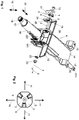
- Fig. 1 an adjustable steering column designed according to the invention is shown, wherein firstly the features of this steering column 4 known in the prior art are briefly described, without this means that in steering columns 4 according to the invention these must be realized in the prior art known features.
- the adjustable steering column 4 a support unit 14, which is fastened by means of the fastening tabs 15 to the body of a vehicle.
- a steering spindle bearing unit 16 is adjustably mounted via a corresponding, known intermediate lever.
- the steering shaft bearing unit 16 together with the steering shaft 17 can be adjusted in length and / or height direction. In the illustrated embodiment, both adjustment directions are possible. Double arrow 19 shows the possible directions for height adjustment. Double arrow 20 shows the directions in the longitudinal adjustment.
- the steering wheel At the steering wheel connection 18, the steering wheel, not shown here, can be attached to the steering shaft 17.
- a universal joint or a steering gear for example, with electric power assistance, known as "Colpas" be arranged.
- the locking device 3 shown here in an exploded view is returned to its closed position in which the position of the steering spindle bearing unit 16 is fixed relative to the support unit 14 and thus to the body of the vehicle is.
- the locking device 3 is adjusted by means of a lever 21 shown here only shortened between its open position and its closed position.
- the lever 21 is in the illustrated embodiment, together with one of the cam carrier 1 or 2, here together with the cam carrier 1, around which, in this embodiment, coaxially through the clamping bolt 13 extending axis of rotation 7 rotatable.
- the further cam carrier 2 is rotatably attached to the support unit 14 in this embodiment via the intermediate part 24.
- the shim may also be replaced by a thrust bearing.
- the first cam carrier 1 has in this embodiment, integrally molded cam 5 and the other cam carrier 2 also integrally molded cam 6.
- the cam carrier 1 and 2 are arranged opposite one another about the rotation axis 7 against each other rotatable. When rotating the first cam carrier 1 against the further cam carrier 2 along the rotation angle 8 about the axis of rotation 7, the cams 5 of the first cam carrier 1 are in each case on one of the cams 6 of the other cam carrier 2 on a contact track 9 sliding along each other.
- the number of arranged on a respective cam carrier 1 or 2 cams 5 and 6 may vary. The minimum is in each case a single cam 5 or 6 per cam carrier 1 or 2.
- the cam carriers 1 and 2 each have three cams 5 and 6, respectively.
- the number of cams per cam carrier can, as I said, vary. In any case, it is advantageous if in each case a cam 5 of the first cam carrier 1 cooperates with a cam 6 of the further cam carrier 2.
- cam carriers 1 and 2 can be used both in frictionally engaged and in positively locking locking devices 3.
- in the shown embodiment can be seen on the teeth 29 that it is here with respect to the height adjustment in the direction of the double arrow 19 is a form-locking locking device 3, and in length adjustment in the direction of the double arrow 20 to a frictional connection, along the contact surfaces 291 between the intermediate lever 141 and the steering shaft bearing unit 16, acts.
- Fig. 2 shows a plan view of the cam 5 of the first cam carrier 1. Also marked is the axis of rotation 7, by which the cam carrier 1 and 2 are rotated against each other by the operation of the manual operating lever 21, and the radial direction 11. Die Fig. 3 to 6 on the cam 6 opposite the back of the other cam carrier 2 two fixing pins 26 are provided in the illustrated embodiment, which engage as rotation in the embodiment shown in corresponding recesses in the intermediate part 24.
- Fig. 6 shows a plan view of the cams 6 and their surfaces.
- the contact tracks 9 are located.
- Fig. 6 is good to see over the course of the angle of rotation 8 changing radial distance 10 between the contact track 9 and the axis of rotation 7.
- the contact tracks 9 have a width 12 which goes beyond a line shape and, in this exemplary embodiment, likewise varies over the longitudinal extent of the contact track 9.
- the distance 10 between the contact track 9 and the axis of rotation 7 is determined by means of the relative to the radial direction 11
- Center line 27 of the contact track 9 determines.
- This is exemplary in 6 and 7 also marked as such. While in Fig. 6 the center line 27 and thus also the hatched contact track 9 is relatively angular, is in Fig. 7 a second variant shown in which the changes in the radial distance 10 are selectively rounded in different radii.
- the design should be carried out depending on the material properties of the cams 5 and 6 or their cam carrier 1 and 2.
- the respective surface pressures should be such that the cam pairings are durable.
- FIG. 8 to 10 are side views of the oppositely arranged cam carrier 1 and 2 and the centrally guided by them clamping bolt 13, wherein the two cam carrier 1 and 2 and thus also their cams 5 and 6 in the various representations of FIGS. 8, 9 and 10 are arranged in relation to each other different angles of rotation 8.
- the distance 28 between the two cam carriers 1 and 2 also varies.
- the situation according to FIG Fig. 8 corresponds to the closed position of the locking device 3 in which the steering shaft bearing unit 16 is fixed relative to the support unit 14 in position.
- Fig. 10 shows the open position of the locking device 3, in which an adjustment of the steering shaft bearing unit 16 in at least one of the directions 19 and 20 relative to the support unit 14 is possible.
- Fig. 9 shows an intermediate position.
- Fig. 11 shows a planar section along the axis of rotation 7 through the arrangement of the two cam carriers 2 and the clamping bolt 13.
- the contact track 9 runs on one of the cam 5 parallel to the contact track 9 on the other cam 6.
- the contact track is orthogonal to the axis of rotation 7, as is the case in preferred embodiments.
- the loaded state is shown, in which the clamping system is in its closed position. The parallel course of the contact track 9 on the two cams 5 and 6 but Conveniently given in the unloaded state, which leads to a total permanent contact of the two cams 5 and 6 in the contact track 9, when the cams 5 and 6 are in contact with each other.
- first cam carrier 171 The End 2 further cam carrier 291 contact area 3 Locking device 4 steering column 5 cam 6 cam 7 axis of rotation 8th angle of twist 9 Contact track 10 radial distance 11 radial direction 12 width 13 clamping bolt 14 support unit 15 mounting tabs 16 Steering shaft bearing unit 17 steering shaft 18 steering wheel connection 19 direction 20 direction 21 Manual control lever 22 locknut 23 washer 24 intermediate part 25 Pocket or recess or depression 26 fixation pin 27 center line 28 distance 29 gearing 141 intermediate lever
Landscapes
- Engineering & Computer Science (AREA)
- Mechanical Engineering (AREA)
- General Engineering & Computer Science (AREA)
- Chemical & Material Sciences (AREA)
- Combustion & Propulsion (AREA)
- Transportation (AREA)
- Steering Controls (AREA)
- Transmission Devices (AREA)
Description
- Die vorliegende Erfindung betrifft eine Anordnung mit einem ersten Nockenträger und zumindest einem weiteren Nockenträger für eine Feststelleinrichtung für eine verstellbare Lenksäule eines Kraftfahrzeugs, wobei die Nockenträgerjeweils zumindest einen Nocken aufweisen und die Nockenträger einander gegenüberliegend um eine Drehachse gegeneinander verdrehbar angeordnet sind und beim Verdrehen des ersten Nockenträgers gegen den weiteren Nockenträger entlang eines Verdrehwinkels um die Drehachse der Nocken des ersten Nockenträgers am Nocken des weiteren Nockenträgers auf einer Kontaktspur entlang gleitend anliegt.
- Gattungsgemäße Anordnungen, wie sie z.B. in der
WO 2009/141045 A1 gezeigt sind, werden in Feststelleinrichtungen bzw. Spanneinrichtungen für verstellbare Lenksäulen für Kraftfahrzeuge eingesetzt. Mittels eines meist von Hand bedienbaren Hebels können die Nockenträger gegeneinander verdreht werden. In einer ersten Stellung befindet sich dann die Feststelleinrichtung in einer geöffneten Stellung, in der die Lenkspindel und damit das an der Lenksäule angebrachte Lenkrad in Höhenund/oder Längsrichtung verstellt werden kann, um die Lage des Lenkrades an die Position des jeweiligen Fahrers anzupassen. Beim Stand der Technik sind unterschiedliche Nockenträger bekannt, bei denen die Nocken unterschiedlich ausgeformt sind, also eine voneinander verschiedene Nockenkontur aufweisen. Häufig wird auch von einem Nocken bzw. Nockenträger und mit diesem zusammenwirkenden Nockenfolger gesprochen. Dies ist aber lediglich eine sprachliche Konvention. Letztendlich handelt es sich bei Nockenträger und Nockenfolger jeweils um Nockenträger mit entsprechenden Nocken. - Ein generelles Problem bei der Darstellung bzw. Ausformung der Nocken besteht darin, auf einem möglichst kurzen Verstellweg bzw. Verdrehwinkel, eine möglichst große Presskraft zur Arretierung der Feststelleinrichtung in ihrer Schließstellung bereitzustellen. Gleichzeitig soll die Handkraft, die zur Betätigung des Hebels der Feststelleinrichtung erforderlich ist, auf einem möglichst niedrigen Niveau gehalten werden und ein angenehmes Betätigungsgefühl vermitteln. Weiterhin soll der Verschleiß am Nocken möglichst gering gehalten werden.
- Die
EP 1 180 466 schlägt zur Verbesserung der Bedienbarkeit vor, die Nockenoberfläche mit einer Vielzahl von Anstiegsrampen auszubilden, deren Anstiege unterschiedlich sind, um einen möglichst gleichmäßigen Übergang der Handkraft in Abhängigkeit vom Verdrehwinkel und damit von der Spannkraft zu erreichen. Im Stand der Technik sind darüber hinaus allgemein kurvenförmige Anstiegsrampen bekannt, so beispielsweise in derJP 2003-231470 A JP 2005-231545 A - Gemäß der
JP 2006-131211 A JP 2006-131211 A - Allen oben genannten Techniken des Standes der Technik ist gemein, dass der Handkraftverlauf nur sehr eingeschränkt optimiert werden kann.
- Aufgabe der Erfindung ist es daher, eine gattungsgemäße Anordnung zur Verfügung zu stellen, bei der der Kraftverlauf beim gegeneinander Verdrehen der Nockenträger um die Drehachse optimal an die Bedürfnisse angepasst werden kann.
- Dies wird erfindungsgemäß durch eine Anordnung gemäß Patentanspruch 1 erreicht.
- Es ist somit vorgesehen, dass die Kontaktspur in einem sich in Abhängigkeit des Verdrehwinkels ändernden radialen Abstand von der Drehachse verläuft.
- Die Kontaktspur und die Nockengeometrien und Kontakte lassen sich vorteilhafterweise in Polarkoordinaten mit dem Verdrehwinkel und dem Abstand in der radialen Richtung von der Drehachse beschreiben.
- Mit anderen Worten ist es somit ein Grundgedanke der Erfindung, in radialer Richtung gesehen, den Abstand des Kontaktes zwischen den beiden Nocken also der Kontaktspur vom Drehzentrum bzw. von der Drehachse über den Verlauf der Kontaktspur variabel zu gestalten. Insbesondere kann dabei vorgesehen sein, dass der radiale Abstand der Kontaktspur über den gesamten Verdrehwinkel entweder permanent zunimmt oder permanent abnimmt, um beim Verdrehen der Nockenträger der Anordnung gegeneinander beim Schließ- und/oder Öffnungsvorgang der Feststelleinrichtung den gewünschten Kraftverlauf zu erreichen.
- Als Kontaktspur ist der Bereich eines Nockenträgers bzw. Nockens zu verstehen, der im Verlauf der Betätigung der Feststelleinrichtung mit dem anderen Nockenträger bzw. Nocken in Kontakt steht, wobei über diesen Kontakt die Spannkraft der Feststelleinrichtung übertragen wird, beziehungsweise die Nockensteuerung der Feststelleinrichtung erfolgt.
- Die Kontaktspur kann sich, im Sinne einer eine Längserstreckung bzw. einen Verlauf aufweisenden Spur, auf beiden der aneinander entlang gleitenden Nocken oder nur auf einem dieser beiden Nocken ausbilden. Günstig ist es jedenfalls, wenn der Nocken des ersten Nockenträgers und der Nocken des weiteren Nockenträgers ausschließlich im Bereich der Kontaktspur miteinander in Kontakt stehen. Unter in Kontakt stehen, wird dabei ein in physischem Kontakt stehen, also ein aneinander anliegen verstanden. Die Kontaktspur kann je nach Ausformung der miteinander in Kontakt stehenden Nocken linienförmig ausgebildet sein, oder aber auch in radialer Richtung bezüglich der Drehachse gesehen eine gewisse Breite aufweisen. Weist die Kontaktspur eine über eine Linie hinausgehende Breite auf, so ist zur Feststellung der Änderung des radialen Abstandes der Kontaktspur von der Drehachse in Abhängigkeit des Verdrehwinkels die in radialer Richtung gesehene Mitte der Kontaktspur heranzuziehen. Mit anderen Worten ist somit im Zweifel der radiale Abstand der Kontaktspur zur Drehachse zwischen der in radialer Richtung gesehenen Mitte der Kontaktspur und der Drehachse zu messen. Um bei einer langfristigen Verwendung der erfindungsgemäßen Anordnung den Abrieb an den aneinander entlang gleitenden Nocken möglichst gering zu halten, sehen bevorzugte Ausgestaltungsformen der Erfindung vor, dass sich, in radialer Richtung bezüglich der Drehachse gesehen, die Breite der Kontaktspur in Abhängigkeit des Verdrehwinkels ändert. In Bereichen, in denen der Verschleiß bzw. der Abrieb besonders hoch ist, kann so der vorzeitigen Abnutzung der Nocken durch eine entsprechend größere Breite der Kontaktspur entgegengewirkt werden. Die Kontaktspur ist zumindest bei einem Nockenträger bzw. Nocken, nach mehrmaligem Gebrauch der Feststelleinrichtung, als Schleifspur erkennbar.
- Besonders bevorzugt ist vorgesehen, dass die aneinander gleitenden Nocken, wenn sie miteinander in Kontakt stehen, zumindest abschnittsweise vollflächig oder voll linienförmig und nicht nur punktuell, aufeinander aufliegen. In diesem Sinne kann es besonders günstig sein, wenn, auch wenn sich die Nocken in einem entlasteten Zustand befinden, die Kontaktspur, vorzugsweise über ihre gesamte Längserstreckung, auf einem der Nocken, in einem ebenen Schnitt entlang der Drehachse gesehen, parallel zur Kontaktspur auf dem anderen Nocken verläuft. In solchen Ausgestaltungsformen liegen die Nocken auch dann vollflächig oder voll linienförmig aneinander an, auch dann wenn sie nur mit geringen Kräften aneinander gedrückt werden bzw. nur locker aneinander anliegen würden.
- In diesem Zusammenhang ist es auch günstig, wenn die Kontaktspur, vorzugsweise über ihre gesamte Längserstreckung, auf zumindest einem der, vorzugsweise auf beiden miteinander in Kontakt stehenden, Nocken in einem ebenen Schnitt entlang der Drehachse gesehen, orthogonal zur Drehachse verläuft bzw. ausgerichtet ist. Die Nocken sind bevorzugt auf den jeweiligen Nockenträgern als einander zugewandte und in Richtung parallel zur Drehachse ausgebildete Vorsprünge des jeweiligen Nockenträgers ausgebildet. Mit anderen Worten handelt es sich bei den Nocken also um eine Art Gebirge, die über die sonstige Kontur des Nockenträgers in Richtung parallel zur Drehachse überstehen. Die Vorsprünge bzw. Nocken können einstückig mit den Nockenträgern ausgeformt sein. Es kann sich aber auch um Nocken handeln, die auf einem Nockenträgergrundkörper mittels Verschrauben, Annieten, Anschweißen, Verpressen oder dergleichen nachträglich befestigt werden.
- Der Vollständigkeit halber wird darauf hingewiesen, dass günstigerweise vorgesehen ist, dass die Kontaktspur, vorzugsweise jeweils, auf der, dem Nocken des anderen Nockenträgers zugewandten Oberfläche zumindest eines der Nocken angeordnet ist. Es ist denkbar und möglich, an beiden Nocken eine Kontaktspur auszubilden. Um den radialen Abstand der Kontaktspur erfindungsgemäß in Abhängigkeit des Verdrehwinkels zu ändern, können in zumindest einem der Nocken bzw. dessen Oberfläche Taschen eingearbeitet sein. Diese Taschen können auch als Vertiefungen oder Ausnehmungen bezeichnet werden. Durch die Einbringung von Taschen wird der Kontakt zwischen den beiden Nocken im Bereich der Taschen verhindert.
- Mit besonderem Vorteil ist vorgesehen, dass der radiale Abstand der Kontaktspur von der Drehachse an einem Ende der Kontaktspur minimal ist. Günstigerweise liegen die Nocken dann an diesem Ende dieser Kontaktspur aneinander an, wenn sich die Feststelleinrichtung in ihrer Schließstellung befindet, in der die verstellbare Lenksäule bzw. das daran angebrachte Lenkrad in seiner Position arretiert ist. In diesem Bereich ist bereits die volle Klemmkraft aufgebracht worden und es erfolgt nur deshalb eine weitere Verdrehung des von Hand bedienbaren Hebels bzw. Klemmhebels, um die Lage des Klemmhebels in der Endposition besser zu sichern. Durch diese Maßnahme wird es möglich, den Fahrer in diesem letzten Bereich ein Gefühl des "Einrastens" zu vermitteln. Bei diesem "Einrasten" erfolgt jedoch kein Abbau der Spannkraft in der Feststelleinrichtung. Dieses Gefühl des "Einrastens" ist auch dann gegeben, wenn in Wahrheit die Betätigungskraft am von Hand betätigbaren Hebel nicht absinkt, sondern nur gleich bleibt, da kurz vor diesem Übergang die Spannkraft sehr stark angestiegen ist.
- Zusätzlich zur oben genannten Anordnung betrifft die Erfindung auch eine Feststelleinrichtung für eine verstellbare Lenksäule eines Kraftfahrzeugs mit einer erfindungsgemäßen Anordnung. Bei dieser kann vorgesehen sein, dass die Nockenträger um die Drehachse gegeneinander verdrehbar auf einem Spannbolzen der Feststelleinrichtung angeordnet sind. In solchen Ausgestaltungsformen ist besonders bevorzugt vorgesehen, dass der Spannbolzen die Nockenträger koaxial zur Drehachse durchdringt. Es kann vorgesehen sein, dass einer der Nockenträger oder Nocken, auch Nockenfolger genannt, drehfest mit dem Spannbolzen verbunden ist. Der weitere bzw. zusätzliche Nockenträger kann dann z.B. an einem an der restlichen Feststelleinrichtung fixierten z.B. fahrzeugfesten Bauteil fixiert sein.
- Günstigerweise weist die Feststelleinrichtung einen von Hand bedienbaren Hebel auf. Der Hebel kann z.B. über den Spannbolzen drehfest mit einem der Nockenträger verbunden sein.
- Alternativ ist es auch denkbar und möglich, einen der Nockenträger, oder Nocken, mit dem Hebel zumindest drehfest zu verbinden und drehbar um die Achse des Spannbolzens auf den Spannbolzen zu lagern. Entscheidend ist allein, dass der Nocken gegenüber dem Nockenfolger (oder mit anderen Worten die beiden Nocken zueinander) verdrehbar ansteuerbar ist.
- Der Vollständigkeit halber wird aber darauf hingewiesen, dass die Erfindung nicht nur bei von Hand über einen Hebel bedienbaren Feststelleinrichtungen sondern auch bei motorisch betriebenen Feststelleinrichtungen, bei denen die Nockenträger mittels eines Motors gegeneinander verdreht werden, eingesetzt werden kann.
- Neben der Anordnung der Feststelleinrichtung betrifft die Erfindung auch eine verstellbare Lenksäule für ein Kraftfahrzeug mit einer erfindungsgemäßen Feststelleinrichtung. Unter einer verstellbaren Lenksäule, insbesondere auch in einer in ihrer Höhe und Länge verstellbaren Lenksäule, wird allgemein eine beim Stand der Technik an sich bekannte Lenksäule verstanden, bei der die Position des an der Lenksäule bzw. dessen Lenkspindel angebrachten Lenkrades an den jeweiligen Fahrer angepasst werden kann. Die Anpassung bzw. Verstellung der Lenksäule erfolgt dann in der Regel bei geöffneter Feststelleinrichtung. Ist die Feststelleinrichtung in ihre Schließstellung gebracht, so ist die Position der Lenksäule bzw. deren Lenkspindel und damit des Lenkrades fixiert. In solchen erfindungsgemäßen Lenksäulen können die beim Stand der Technik an sich bekannten Energieabsorptionsmechanismen für den Crashfall integriert sein.
- Weitere Merkmale und Einzelheiten bevorzugter Ausgestaltungsformen der Erfindung werden anhand der nachfolgenden Figurenbeschreibung erläutert. Es zeigen:
-
Fig. 1 eine erfindungsgemäß ausgerüstete verstellbare Lenksäule für ein Kraftfahrzeug; -
Fig. 2 den inFig. 1 zum Einsatz kommende erste Nockenträger; -
Fig. 3 bis 6 den inFig. 1 zum Einsatz kommende weiteren bzw. zusätzlichen Nockenträger in verschiedenen Ansichten; -
Fig. 7 eine alternative Ausgestaltungsform eines erfindungsgemäßen weiteren Nockenträgers; -
Fig. 8 bis 10 verschiedene Stellungen der Nockenträger relativ zueinander bei verschiedenen Verdrehwinkeln; -
Fig. 11 einen schematisierten Längsschnitt entlang der Drehachse durch die Nockenträger und den Spannbolzen. - In
Fig. 1 ist eine erfindungsgemäß ausgebildete verstellbare Lenksäule dargestellt, wobei zunächst die beim Stand der Technik an sich bekannten Merkmale dieser Lenksäule 4 kurz geschildert werden, ohne dass dies bedeutet, dass bei erfindungsgemäßen Lenksäulen 4 diese beim Stand der Technik an sich bekannten Merkmale realisiert sein müssen. - Im in
Fig. 1 dargestellten Ausführungsbeispiel weist die verstellbare Lenksäule 4 eine Trageinheit 14 auf, welche mittels der Befestigungslaschen 15 an der Karosserie eines Fahrzeugs befestigt wird. An der Trageinheit 14 ist, gegebenenfalls über einen entsprechenden, an sich bekannten Zwischenhebel eine Lenkspindellagereinheit 16 verstellbar gelagert. Zur Verstellung muss zunächst die Feststelleinrichtung 3 in ihre geöffnete Position gebracht werden. In dieser geöffneten Stellung der Feststelleinrichtung 3 kann die Lenkspindellagereinheit 16 samt Lenkspindel 17 in Längen- und/oder Höhenrichtung verstellt werden. Im gezeigten Ausführungsbeispiel sind beide Verstellrichtungen möglich. Doppelpfeil 19 zeigt die möglichen Richtungen bei der Höhenverstellung. Doppelpfeil 20 zeigt die Richtungen bei der Längsverstellung. Am Lenkradanschluss 18 kann das hier nicht dargestellte Lenkrad an der Lenkspindel 17 befestigt werden. Am vorderen Ende 171 der Lenkspindel kann ein Universalgelenk oder ein Lenkgetriebe, beispielsweise mit elektrischer Hilfskraftunterstützung, bekannt unter dem Namen "Colpas", angeordnet sein. - Ist die gewünschte Verstellung der Position der Lenkspindellagereinheit 16 und damit des Lenkrades durchgeführt worden, so wird die hier in einer Explosionsdarstellung gezeigte Feststelleinrichtung 3 wieder in ihre Schließstellung gebracht, in der die Position der Lenkspindellagereinheit 16 relativ zur Trageinheit 14 und damit zur Karosserie des Fahrzeugs fixiert ist.
- Im gezeigten Ausführungsbeispiel wird die Feststelleinrichtung 3 mittels eines hier nur verkürzt dargestellten Hebels 21 zwischen seiner geöffneten Stellung und seiner Schließstellung verstellt. Der Hebel 21 ist im gezeigten Ausführungsbeispiel zusammen mit einem der Nockenträger 1 oder 2, hier zusammen mit dem Nockenträger 1, um die, in diesem Ausführungsbeispiel koaxial durch den Spannbolzen 13 verlaufende Drehachse 7 verdrehbar. Der weitere Nockenträger 2 ist in diesem Ausführungsbeispiel über das Zwischenteil 24 drehfest an der Trageinheit 14 befestigt. Durch Verdrehen des Hebels 21 mitsamt des ersten Nockenträgers 1 werden der Nockenträger 1 und der weitere Nockenträger 2 relativ zueinander um die Drehachse 7 über einen entsprechend vorgegebenen Verdrehwinkel 8 gegeneinander verdreht. Der Spannbolzen 13 dieses Ausführungsbeispiels ist auf der dem Hebel 21 gegenüberliegenden Seite mittels Beilagscheibe 23 und Gegenmutter 22 gesichert. Die Beilagsscheibe kann auch durch ein Axiallager ersetzt sein. Der erste Nockenträger 1 weist in diesem Ausführungsbeispiel einstückig angeformte Nocken 5 und der weitere Nockenträger 2 ebenfalls einstückig angeformte Nocken 6 auf. Die Nockenträger 1 und 2 sind einander gegenüberliegend um die Drehachse 7 gegeneinander verdrehbar angeordnet. Beim Verdrehen des ersten Nockenträgers 1 gegen den weiteren Nockenträger 2 entlang des Verdrehwinkels 8 um die Drehachse 7 liegen die Nocken 5 des ersten Nockenträgers 1 an jeweils einem der Nocken 6 des weiteren Nockenträgers 2 auf einer Kontaktspur 9 aneinander entlang gleitend an. Der Vollständigkeit halber wird darauf hingewiesen, dass die Anzahl der auf einem jeweiligen Nockenträger 1 oder 2 angeordneten Nocken 5 bzw. 6 variieren kann. Das Minimum ist jeweils ein einzelner Nocken 5 bzw. 6 pro Nockenträger 1 oder 2. Im gezeigten Ausführungsbeispiel weisen die Nockenträger 1 und 2 jeweils drei Nocken 5 bzw. 6 auf. Die Zahl der Nocken pro Nockenträger kann aber, wie gesagt, variieren. Günstig ist es jedenfalls, wenn jeweils ein Nocken 5 des ersten Nockenträgers 1 mit einem Nocken 6 des weiteren Nockenträgers 2 zusammenwirkt.
- Der Vollständigkeit halber wird darauf hingewiesen, dass erfindungsgemäße Anordnungen von Nockenträgern 1 und 2 sowohl bei reibschlüssig als auch bei formschlüssig arbeitenden Feststelleinrichtungen 3 eingesetzt werden können. Im gezeigten Ausführungsbeispiel ist an den Verzahnungen 29 zu erkennen, dass es sich hier in Bezug auf die Höhenverstellung in Richtung des Doppelpfeils 19 um eine formschlüssig arbeitende Feststelleinrichtung 3 handelt, und in Längenverstellrichtung in Richtung des Doppelpfeils 20 um eine reibschlüssige Verbindung, entlang der Kontaktflächen 291 zwischen dem Zwischenhebel 141 und der Lenkspindellagereinheit 16, handelt.
-
Fig. 2 zeigt eine Draufsicht auf die Nocken 5 des ersten Nockenträgers 1. Eingezeichnet ist auch die Drehachse 7, um die die Nockenträger 1 und 2 gegeneinander durch die Betätigung des Handbedienhebels 21 verdreht werden, sowie die radiale Richtung 11. DieFig. 3 bis 6 zeigen das Gegenstück, also den weiteren Nockenträger 2 mit seinen Nocken 6. Auf der den Nocken 6 gegenüberliegenden Rückseite des weiteren Nockenträgers 2 sind im gezeigten Ausführungsbeispiel zwei Fixierungszapfen 26 vorgesehen, welche als Verdrehsicherung im gezeigten Ausführungsbeispiel in entsprechende Ausnehmungen im Zwischenteil 24 eingreifen. Um in Zusammenwirkung mit den Nocken 5 des ersten Nockenträgers 1, den erfindungsgemäß variierenden radialen Abstand 10 der Kontaktspur 9 von der Drehachse 7 in Abhängigkeit des Verdrehwinkels 8 zu realisieren, sind im gezeigten Ausführungsbeispiel Taschen bzw. Vertiefungen 25 in den Nocken 6 bzw. in deren Oberflächen vorgesehen. -
Fig. 6 zeigt eine Draufsicht auf die Nocken 6 bzw. deren Oberflächen. In dieser Draufsicht sind auch die Kontaktspuren 9 eingezeichnet. In dieser Draufsicht gemäßFig. 6 ist gut der sich über den Verlauf des Verdrehwinkels 8 ändernde radiale Abstand 10 zwischen der Kontaktspur 9 und der Drehachse 7 zu sehen. Bei der dargestellten Variante weisen die Kontaktspuren 9 eine über eine Linienform hinausgehende Breite 12 auf, welche in diesem Ausführungsbeispiel ebenfalls über die Längserstreckung der Kontaktspur 9 hinweg variiert. - In solchen Fällen, in denen die Breite 12 der Kontaktspur 9 in radialer Richtung 11 nicht zu vernachlässigen ist, wird der Abstand 10 zwischen Kontaktspur 9 und Drehachse 7 mit Hilfe der bezogen auf die radiale Richtung 11 bestimmten Mittellinie 27 der Kontaktspur 9 bestimmt. Dies ist beispielhaft in
Fig. 6 und 7 auch so eingezeichnet. Während inFig. 6 die Mittellinie 27 und damit auch die schraffiert eingezeichnete Kontaktspur 9 relativ eckig verläuft, ist inFig. 7 eine zweite Variante dargestellt, bei der die Änderungen des radialen Abstandes 10 in verschiedenen Radien gezielt abgerundet sind. Darüber hinaus ist es natürlich auch denkbar und möglich, andere Verläufe von Kontaktspuren 9 zu realisieren, zum Beispiel um im Bereich des größten Anstiegs der Nockenrampe eine Abschwächung der am Hebel 21 benötigten Kraft zu erreichen. Die Auslegung sollte dabei in Abhängigkeit von den Werkstoffeigenschaften der Nocken 5 und 6 bzw. deren Nockenträger 1 und 2 erfolgen. Die jeweiligen Flächenpressungen sollten so bemessen sein, dass die Nockenpaarungen dauerhaft haltbar sind. - In den
Fig. 8 bis 10 sind Seitenansichten auf die einander gegenüberliegend angeordneten Nockenträger 1 und 2 und den durch sie zentral hindurchgeführten Spannbolzen 13 dargestellt, wobei die beiden Nockenträger 1 und 2 und damit auch ihre Nocken 5 und 6 in den verschiedenen Darstellungen derFig. 8, 9 und 10 in relativ zueinander verschiedenen Verdrehwinkeln 8 angeordnet sind. Entsprechend variiert auch die Distanz 28 zwischen den beiden Nockenträgern 1 und 2. Die Situation gemäßFig. 8 entspricht der Schließstellung der Feststelleinrichtung 3 in der die Lenkspindellagereinheit 16 relativ zur Trageinheit 14 in ihrer Position fixiert ist.Fig. 10 zeigt die geöffnete Stellung der Feststelleinrichtung 3, bei der eine Verstellung der Lenkspindellagereinheit 16 in zumindest einer der Richtungen 19 und 20 relativ zur Trageinheit 14 möglich ist.Fig. 9 zeigt eine Zwischenstellung. -
Fig. 11 zeigt einen ebenen Schnitt entlang der Drehachse 7 durch die Anordnung aus den beiden Nockenträgern 2 und dem Spannbolzen 13. Gut zu sehen ist hier, dass vorzugsweise die Kontaktspur 9 auf einem der Nocken 5 parallel zur Kontaktspur 9 auf dem anderen Nocken 6 verläuft. Weiters ist auch zu sehen, dass, in diesem Schnitt gesehen, die Kontaktspur orthogonal zur Drehachse 7 verläuft, wie dies bei bevorzugten Ausgestaltungsformen der Fall ist. InFig. 11 ist der belastete Zustand gezeigt, bei dem das Klemmsystem sich in seiner Schließstellung befindet. Der parallele Verlauf der Kontaktspur 9 auf den beiden Nocken 5 und 6 ist aber günstigerweise auch im entlasteten Zustand gegeben, was insgesamt zu einem permanent vollflächigen Aufliegen der beiden Nocken 5 und 6 im Bereich der Kontaktspur 9 führt, wenn die Nocken 5 und 6 in Kontakt miteinander stehen. -
1 erster Nockenträger 171 Ende 2 weiterer Nockenträger 291 Kontaktfläche 3 Feststelleinrichtung 4 Lenksäule 5 Nocken 6 Nocken 7 Drehachse 8 Verdrehwinkel 9 Kontaktspur 10 radialer Abstand 11 radiale Richtung 12 Breite 13 Spannbolzen 14 Trageinheit 15 Befestigungslaschen 16 Lenkspindellagereinheit 17 Lenkspindel 18 Lenkradanschluss 19 Richtung 20 Richtung 21 Handbedienhebel 22 Gegenmutter 23 Beilagscheibe 24 Zwischenteil 25 Tasche bzw. Ausnehmung bzw. Vertiefung 26 Fixierungszapfen 27 Mittellinie 28 Distanz 29 Verzahnung 141 Zwischenhebel
Claims (10)
- Anordnung mit einem ersten Nockenträger (1) und zumindest einem weiteren Nockenträger (2) für eine Feststelleinrichtung (3) für eine verstellbare Lenksäule (4) eines Kraftfahrzeugs, wobei die Nockenträger (1, 2) jeweils zumindest einen Nocken (5, 6) aufweisen und die Nockenträger (1, 2) einander gegenüberliegend um eine Drehachse (7) gegeneinander verdrehbar angeordnet sind und beim Verdrehen des ersten Nockenträgers (1) gegen den weiteren Nockenträger (2) entlang eines Verdrehwinkels (8) um die Drehachse (7) der Nocken (5) des ersten Nockenträgers (1) am Nocken (6) des weiteren Nockenträgers (2) auf einer Kontaktspur (9) entlang gleitend anliegt, dadurch gekennzeichnet, dass die Kontaktspur (9) in einem sich in Abhängigkeit des Verdrehwinkels (8) ändernden radialen Abstand (10) von der Drehachse (7) verläuft.
- Anordnung nach Anspruch 1, dadurch gekennzeichnet, dass der Nocken (5) des ersten Nockenträgers (1) und der Nocken (6) des weiteren Nockenträgers (2) ausschließlich im Bereich der Kontaktspur (9) miteinander in Kontakt stehen.
- Anordnung nach Anspruch 1 oder 2, dadurch gekennzeichnet, dass sich, in radialer Richtung (11) bezüglich der Drehachse (7) gesehen, die Breite (12) der Kontaktspur (9) in Abhängigkeit des Verdrehwinkels (8) ändert.
- Anordnung nach einem der Ansprüche 1 bis 3, dadurch gekennzeichnet, dass, auch wenn sich die Nocken (5, 6) in einem entlasteten Zustand befinden, die Kontaktspur (9), vorzugsweise über ihre gesamte Längserstreckung, auf einem der Nocken (5), in einem ebenen Schnitt entlang der Drehachse (7) gesehen, parallel zur Kontaktspur (9) auf dem anderen Nocken (6) verläuft.
- Anordnung nach einem der Ansprüche 1 bis 4, dadurch gekennzeichnet, dass die Kontaktspur (9), vorzugsweise über ihre gesamte Längserstreckung, auf zumindest einem der, vorzugsweise auf beiden miteinander in Kontakt stehenden, Nocken (5, 6) in einem ebenen Schnitt entlang der Drehachse (7) gesehen, orthogonal zur Drehachse (7) verläuft.
- Anordnung nach einem der Ansprüche 1 bis 5, dadurch gekennzeichnet, dass die Nocken (5, 6) auf den jeweiligen Nockenträgern (1, 2) als einander zugewandte und in Richtung parallel zur Drehachse (7) ausgebildete Vorsprünge des jeweiligen Nockenträgers (1, 2) ausgebildet sind.
- Anordnung nach Anspruch 6, dadurch gekennzeichnet, dass die Kontaktspur (9), vorzugsweise jeweils, auf der, dem Nocken (5, 6) des anderen Nockenträgers (1, 2) zugewandten Oberfläche zumindest eines der Nocken (5, 6) angeordnet ist.
- Feststelleinrichtung (3) für eine verstellbare Lenksäule (4) eines Kraftfahrzeugs mit einer Anordnung nach einem der Ansprüche 1 bis 7.
- Feststelleinrichtung (3) nach Anspruch 8, dadurch gekennzeichnet, dass die Nockenträger (1, 2) um die Drehachse (7) gegeneinander verdrehbar auf einem Spannbolzen (13) der Feststelleinrichtung (3) angeordnet sind, wobei vorzugsweise vorgesehen ist, dass der Spannbolzen (13) die Nockenträger (1, 2) koaxial zur Drehachse (7) durchdringt.
- Verstellbare Lenksäule (4) für ein Kraftfahrzeug mit einer Feststelleinrichtung (3) nach einem der Ansprüche 8 oder 9.
Priority Applications (1)
| Application Number | Priority Date | Filing Date | Title |
|---|---|---|---|
| PL12772065T PL2763884T3 (pl) | 2011-10-05 | 2012-08-16 | Układ z pierwszym nośnikiem krzywkowym |
Applications Claiming Priority (2)
| Application Number | Priority Date | Filing Date | Title |
|---|---|---|---|
| DE102011054196A DE102011054196B3 (de) | 2011-10-05 | 2011-10-05 | Anordnung mit einem ersten Nockenträger |
| PCT/EP2012/003485 WO2013050095A1 (de) | 2011-10-05 | 2012-08-16 | Anordnung mit einem ersten nockenträger |
Publications (2)
| Publication Number | Publication Date |
|---|---|
| EP2763884A1 EP2763884A1 (de) | 2014-08-13 |
| EP2763884B1 true EP2763884B1 (de) | 2017-05-03 |
Family
ID=47016672
Family Applications (1)
| Application Number | Title | Priority Date | Filing Date |
|---|---|---|---|
| EP12772065.4A Active EP2763884B1 (de) | 2011-10-05 | 2012-08-16 | Anordnung mit einem ersten nockenträger |
Country Status (7)
| Country | Link |
|---|---|
| US (1) | US9308931B2 (de) |
| EP (1) | EP2763884B1 (de) |
| CN (1) | CN103874618B (de) |
| DE (1) | DE102011054196B3 (de) |
| ES (1) | ES2636337T3 (de) |
| PL (1) | PL2763884T3 (de) |
| WO (1) | WO2013050095A1 (de) |
Families Citing this family (13)
| Publication number | Priority date | Publication date | Assignee | Title |
|---|---|---|---|---|
| GB201110277D0 (en) * | 2011-06-17 | 2011-08-03 | Trw Ltd | A clamp assembly for a steering column assembly |
| DE102011055410A1 (de) | 2011-11-16 | 2013-05-16 | Thyssenkrupp Presta Aktiengesellschaft | Feststelleinrichtung für eine verstellbare Lenksäule für ein Kraftfahrzeug |
| DE102011057104B4 (de) | 2011-12-28 | 2016-03-10 | Thyssenkrupp Presta Aktiengesellschaft | Feststelleinrichtung für eine verstellbare Lenksäule |
| DE102012100486B3 (de) | 2012-01-20 | 2013-02-28 | Thyssenkrupp Presta Aktiengesellschaft | Lenksäule für ein Kraftfahrzeug |
| DE102012102556B3 (de) | 2012-03-26 | 2013-06-27 | Thyssenkrupp Presta Aktiengesellschaft | Aufsteckkörper für einen Spannbolzen |
| GB201408170D0 (en) * | 2014-05-08 | 2014-06-25 | Trw Ltd | A clamp mechanism |
| FR3035057B1 (fr) * | 2015-04-15 | 2018-07-27 | Zf Systemes De Direction Nacam S.A.S. | Mecanisme de serrage a cames et colonne de direction associee |
| CN104989657B (zh) * | 2015-06-12 | 2017-05-17 | 太原理工大学 | 长轴驱动的对旋叶轮通风设备 |
| JP6689692B2 (ja) * | 2016-07-12 | 2020-04-28 | 株式会社ジェイテクト | 締付装置およびステアリング装置 |
| US10913483B2 (en) * | 2019-04-04 | 2021-02-09 | Steering Solutions Ip Holding Corporation | Damper assembly for steering column |
| US11279393B2 (en) * | 2020-04-29 | 2022-03-22 | Steering Solutions Ip Holding Corporation | Inner cam assembly for steering rake adjustment assembly |
| CN116677758B (zh) * | 2023-06-15 | 2026-03-24 | 漳州宏兴泰电子有限公司 | 往复变直径传动轮装置 |
| US12319336B1 (en) * | 2023-11-28 | 2025-06-03 | Steering Solutions Ip Holding Corporation | Customizable cam clamping assembly for steering column |
Family Cites Families (14)
| Publication number | Priority date | Publication date | Assignee | Title |
|---|---|---|---|---|
| EP1180466B1 (de) * | 2000-08-11 | 2005-02-09 | Koyo Seiko Co., Ltd. | Schwenkbare einstellbare Lenkvorrichtung |
| JP3906092B2 (ja) * | 2002-02-08 | 2007-04-18 | 株式会社ジェイテクト | チルトステアリング装置 |
| JP4421912B2 (ja) * | 2004-02-20 | 2010-02-24 | 株式会社山田製作所 | ステアリング装置の固定装置 |
| JP2006131211A (ja) * | 2004-10-08 | 2006-05-25 | Nsk Ltd | ステアリングコラム装置 |
| WO2006086523A1 (en) * | 2005-02-09 | 2006-08-17 | Timken Us Corporation | Roller thrust assembly |
| KR101031627B1 (ko) | 2007-10-31 | 2011-04-27 | 후지키코 가부시키가이샤 | 스티어링 칼럼 장치 |
| DE102008024405A1 (de) | 2008-05-20 | 2010-01-28 | Thyssenkrupp Presta Ag | Spannbolzen für eine Feststelleinrichtung einer verstellbaren Lenksäule |
| FR2933058B1 (fr) | 2008-06-30 | 2010-08-27 | Zf Systemes De Direction Nacam Sas | Dispositif d'assistance au verrouillage d'une colonne de direction |
| DE102008045143B4 (de) * | 2008-09-01 | 2012-05-24 | Thyssenkrupp Presta Ag | Verstellbare Lenksäule für ein Kraftfahrzeug |
| CN201321071Y (zh) * | 2008-12-05 | 2009-10-07 | 比亚迪股份有限公司 | 车辆的转向管柱 |
| CN201484477U (zh) * | 2009-09-07 | 2010-05-26 | 四川绵阳三力股份有限公司 | 可调式转向柱总成的调节锁紧机构 |
| JP5785108B2 (ja) * | 2011-03-28 | 2015-09-24 | 株式会社山田製作所 | ステアリング装置 |
| EP2692610B1 (de) * | 2011-03-31 | 2016-08-24 | NSK Ltd. | Lenksäulenvorrichtung |
| EP2927091B1 (de) * | 2012-11-28 | 2018-01-03 | NSK Ltd. | Vorrichtung zur einstellung einer lenkradposition |
-
2011
- 2011-10-05 DE DE102011054196A patent/DE102011054196B3/de not_active Expired - Fee Related
-
2012
- 2012-08-16 WO PCT/EP2012/003485 patent/WO2013050095A1/de not_active Ceased
- 2012-08-16 CN CN201280048622.0A patent/CN103874618B/zh active Active
- 2012-08-16 PL PL12772065T patent/PL2763884T3/pl unknown
- 2012-08-16 EP EP12772065.4A patent/EP2763884B1/de active Active
- 2012-08-16 ES ES12772065.4T patent/ES2636337T3/es active Active
- 2012-08-16 US US14/349,813 patent/US9308931B2/en active Active
Also Published As
| Publication number | Publication date |
|---|---|
| WO2013050095A1 (de) | 2013-04-11 |
| EP2763884A1 (de) | 2014-08-13 |
| US20140318304A1 (en) | 2014-10-30 |
| ES2636337T3 (es) | 2017-10-05 |
| CN103874618B (zh) | 2016-11-09 |
| CN103874618A (zh) | 2014-06-18 |
| DE102011054196B3 (de) | 2012-12-20 |
| PL2763884T3 (pl) | 2017-10-31 |
| US9308931B2 (en) | 2016-04-12 |
Similar Documents
| Publication | Publication Date | Title |
|---|---|---|
| DE102011054196B3 (de) | Anordnung mit einem ersten Nockenträger | |
| EP2307259B1 (de) | Lenksäule für ein kraftfahrzeug | |
| EP2504219B1 (de) | Lenksäule für ein kraftfahrzeug | |
| EP2797804B1 (de) | Feststelleinrichtung für eine verstellbare lenksäule | |
| EP2855237B1 (de) | Lenksäule für ein kraftfahrzeug | |
| EP2233381B1 (de) | Kostengünstiges Zahnstangenlenkgetriebe | |
| WO2015162019A1 (de) | Lenkwelle für ein kraftfahrzeug | |
| DE102012219888A1 (de) | Zahnstange für eine Zahnstangenlenkung eines Kraftfahrzeuges | |
| DE102008024405A1 (de) | Spannbolzen für eine Feststelleinrichtung einer verstellbaren Lenksäule | |
| EP3112237B1 (de) | Kraftfahrzeug mit einer luftleitelementanordnung | |
| EP3215411A1 (de) | Rückstellmomenterzeugungsvorrichtungen | |
| WO2012152487A1 (de) | Druckstück einer zahnstangenlenkung | |
| EP2669155B1 (de) | Anhänger-Rangierantrieb mit Getriebe mit nicht paralleler Achsanordnung | |
| WO2014037579A1 (de) | Zahnstange für ein lenksystem eines kraftfahrzeugs, lenkgetriebe und druckstück | |
| DE102018126714A1 (de) | Lenksäule für ein Kraftfahrzeug | |
| DE102004042283B4 (de) | Lenksäulenanordnung | |
| EP3911553B1 (de) | Lenksäule für ein kraftfahrzeug | |
| DE102017212073A1 (de) | Zahnstangengetriebe für ein Kraftfahrzeug | |
| WO2006002790A1 (de) | Überlagerungslenkung | |
| DE10254129B4 (de) | Elektromotorischer Möbelantrieb zum Verstellen von Teilen eines Möbels relativ zueinander | |
| EP2972644B1 (de) | Eingabeeinheit für ein druck- und drehbetätigbares bedienelement | |
| DE102022211973A1 (de) | Lenkgetriebe für ein Steer-by-Wire-Lenksystem | |
| DE19737034B4 (de) | Lenkmodul eines Kraftfahrzeugs mit sowohl in ihrer Neigung als auch in der Länge verstellbarer Lenksäule | |
| EP2213410B1 (de) | Linearführung mit Klemmvorrichtung | |
| DE102015013648A1 (de) | Kugelrückführung mit axial montierbarer Befestigungshülse |
Legal Events
| Date | Code | Title | Description |
|---|---|---|---|
| PUAI | Public reference made under article 153(3) epc to a published international application that has entered the european phase |
Free format text: ORIGINAL CODE: 0009012 |
|
| 17P | Request for examination filed |
Effective date: 20140210 |
|
| AK | Designated contracting states |
Kind code of ref document: A1 Designated state(s): AL AT BE BG CH CY CZ DE DK EE ES FI FR GB GR HR HU IE IS IT LI LT LU LV MC MK MT NL NO PL PT RO RS SE SI SK SM TR |
|
| DAX | Request for extension of the european patent (deleted) | ||
| GRAP | Despatch of communication of intention to grant a patent |
Free format text: ORIGINAL CODE: EPIDOSNIGR1 |
|
| GRAJ | Information related to disapproval of communication of intention to grant by the applicant or resumption of examination proceedings by the epo deleted |
Free format text: ORIGINAL CODE: EPIDOSDIGR1 |
|
| GRAP | Despatch of communication of intention to grant a patent |
Free format text: ORIGINAL CODE: EPIDOSNIGR1 |
|
| INTG | Intention to grant announced |
Effective date: 20170103 |
|
| INTG | Intention to grant announced |
Effective date: 20170113 |
|
| GRAS | Grant fee paid |
Free format text: ORIGINAL CODE: EPIDOSNIGR3 |
|
| GRAA | (expected) grant |
Free format text: ORIGINAL CODE: 0009210 |
|
| AK | Designated contracting states |
Kind code of ref document: B1 Designated state(s): AL AT BE BG CH CY CZ DE DK EE ES FI FR GB GR HR HU IE IS IT LI LT LU LV MC MK MT NL NO PL PT RO RS SE SI SK SM TR |
|
| REG | Reference to a national code |
Ref country code: GB Ref legal event code: FG4D Free format text: NOT ENGLISH |
|
| REG | Reference to a national code |
Ref country code: AT Ref legal event code: REF Ref document number: 889629 Country of ref document: AT Kind code of ref document: T Effective date: 20170515 Ref country code: CH Ref legal event code: EP |
|
| REG | Reference to a national code |
Ref country code: IE Ref legal event code: FG4D Free format text: LANGUAGE OF EP DOCUMENT: GERMAN |
|
| REG | Reference to a national code |
Ref country code: DE Ref legal event code: R096 Ref document number: 502012010253 Country of ref document: DE |
|
| REG | Reference to a national code |
Ref country code: FR Ref legal event code: PLFP Year of fee payment: 6 |
|
| REG | Reference to a national code |
Ref country code: NL Ref legal event code: MP Effective date: 20170503 |
|
| REG | Reference to a national code |
Ref country code: LT Ref legal event code: MG4D |
|
| REG | Reference to a national code |
Ref country code: ES Ref legal event code: FG2A Ref document number: 2636337 Country of ref document: ES Kind code of ref document: T3 Effective date: 20171005 |
|
| PG25 | Lapsed in a contracting state [announced via postgrant information from national office to epo] |
Ref country code: HR Free format text: LAPSE BECAUSE OF FAILURE TO SUBMIT A TRANSLATION OF THE DESCRIPTION OR TO PAY THE FEE WITHIN THE PRESCRIBED TIME-LIMIT Effective date: 20170503 Ref country code: FI Free format text: LAPSE BECAUSE OF FAILURE TO SUBMIT A TRANSLATION OF THE DESCRIPTION OR TO PAY THE FEE WITHIN THE PRESCRIBED TIME-LIMIT Effective date: 20170503 Ref country code: NO Free format text: LAPSE BECAUSE OF FAILURE TO SUBMIT A TRANSLATION OF THE DESCRIPTION OR TO PAY THE FEE WITHIN THE PRESCRIBED TIME-LIMIT Effective date: 20170803 Ref country code: LT Free format text: LAPSE BECAUSE OF FAILURE TO SUBMIT A TRANSLATION OF THE DESCRIPTION OR TO PAY THE FEE WITHIN THE PRESCRIBED TIME-LIMIT Effective date: 20170503 Ref country code: GR Free format text: LAPSE BECAUSE OF FAILURE TO SUBMIT A TRANSLATION OF THE DESCRIPTION OR TO PAY THE FEE WITHIN THE PRESCRIBED TIME-LIMIT Effective date: 20170804 |
|
| PG25 | Lapsed in a contracting state [announced via postgrant information from national office to epo] |
Ref country code: NL Free format text: LAPSE BECAUSE OF FAILURE TO SUBMIT A TRANSLATION OF THE DESCRIPTION OR TO PAY THE FEE WITHIN THE PRESCRIBED TIME-LIMIT Effective date: 20170503 Ref country code: SE Free format text: LAPSE BECAUSE OF FAILURE TO SUBMIT A TRANSLATION OF THE DESCRIPTION OR TO PAY THE FEE WITHIN THE PRESCRIBED TIME-LIMIT Effective date: 20170503 Ref country code: RS Free format text: LAPSE BECAUSE OF FAILURE TO SUBMIT A TRANSLATION OF THE DESCRIPTION OR TO PAY THE FEE WITHIN THE PRESCRIBED TIME-LIMIT Effective date: 20170503 Ref country code: BG Free format text: LAPSE BECAUSE OF FAILURE TO SUBMIT A TRANSLATION OF THE DESCRIPTION OR TO PAY THE FEE WITHIN THE PRESCRIBED TIME-LIMIT Effective date: 20170803 Ref country code: LV Free format text: LAPSE BECAUSE OF FAILURE TO SUBMIT A TRANSLATION OF THE DESCRIPTION OR TO PAY THE FEE WITHIN THE PRESCRIBED TIME-LIMIT Effective date: 20170503 Ref country code: IS Free format text: LAPSE BECAUSE OF FAILURE TO SUBMIT A TRANSLATION OF THE DESCRIPTION OR TO PAY THE FEE WITHIN THE PRESCRIBED TIME-LIMIT Effective date: 20170903 |
|
| PG25 | Lapsed in a contracting state [announced via postgrant information from national office to epo] |
Ref country code: EE Free format text: LAPSE BECAUSE OF FAILURE TO SUBMIT A TRANSLATION OF THE DESCRIPTION OR TO PAY THE FEE WITHIN THE PRESCRIBED TIME-LIMIT Effective date: 20170503 Ref country code: DK Free format text: LAPSE BECAUSE OF FAILURE TO SUBMIT A TRANSLATION OF THE DESCRIPTION OR TO PAY THE FEE WITHIN THE PRESCRIBED TIME-LIMIT Effective date: 20170503 Ref country code: SK Free format text: LAPSE BECAUSE OF FAILURE TO SUBMIT A TRANSLATION OF THE DESCRIPTION OR TO PAY THE FEE WITHIN THE PRESCRIBED TIME-LIMIT Effective date: 20170503 Ref country code: RO Free format text: LAPSE BECAUSE OF FAILURE TO SUBMIT A TRANSLATION OF THE DESCRIPTION OR TO PAY THE FEE WITHIN THE PRESCRIBED TIME-LIMIT Effective date: 20170503 |
|
| REG | Reference to a national code |
Ref country code: DE Ref legal event code: R097 Ref document number: 502012010253 Country of ref document: DE |
|
| PG25 | Lapsed in a contracting state [announced via postgrant information from national office to epo] |
Ref country code: SM Free format text: LAPSE BECAUSE OF FAILURE TO SUBMIT A TRANSLATION OF THE DESCRIPTION OR TO PAY THE FEE WITHIN THE PRESCRIBED TIME-LIMIT Effective date: 20170503 |
|
| PLBE | No opposition filed within time limit |
Free format text: ORIGINAL CODE: 0009261 |
|
| STAA | Information on the status of an ep patent application or granted ep patent |
Free format text: STATUS: NO OPPOSITION FILED WITHIN TIME LIMIT |
|
| REG | Reference to a national code |
Ref country code: CH Ref legal event code: PL |
|
| PG25 | Lapsed in a contracting state [announced via postgrant information from national office to epo] |
Ref country code: MC Free format text: LAPSE BECAUSE OF FAILURE TO SUBMIT A TRANSLATION OF THE DESCRIPTION OR TO PAY THE FEE WITHIN THE PRESCRIBED TIME-LIMIT Effective date: 20170503 |
|
| 26N | No opposition filed |
Effective date: 20180206 |
|
| PG25 | Lapsed in a contracting state [announced via postgrant information from national office to epo] |
Ref country code: CH Free format text: LAPSE BECAUSE OF NON-PAYMENT OF DUE FEES Effective date: 20170831 Ref country code: LI Free format text: LAPSE BECAUSE OF NON-PAYMENT OF DUE FEES Effective date: 20170831 |
|
| REG | Reference to a national code |
Ref country code: IE Ref legal event code: MM4A |
|
| PG25 | Lapsed in a contracting state [announced via postgrant information from national office to epo] |
Ref country code: SI Free format text: LAPSE BECAUSE OF FAILURE TO SUBMIT A TRANSLATION OF THE DESCRIPTION OR TO PAY THE FEE WITHIN THE PRESCRIBED TIME-LIMIT Effective date: 20170503 |
|
| REG | Reference to a national code |
Ref country code: BE Ref legal event code: MM Effective date: 20170831 |
|
| PG25 | Lapsed in a contracting state [announced via postgrant information from national office to epo] |
Ref country code: LU Free format text: LAPSE BECAUSE OF NON-PAYMENT OF DUE FEES Effective date: 20170816 |
|
| PG25 | Lapsed in a contracting state [announced via postgrant information from national office to epo] |
Ref country code: IE Free format text: LAPSE BECAUSE OF NON-PAYMENT OF DUE FEES Effective date: 20170816 |
|
| REG | Reference to a national code |
Ref country code: FR Ref legal event code: PLFP Year of fee payment: 7 |
|
| PG25 | Lapsed in a contracting state [announced via postgrant information from national office to epo] |
Ref country code: BE Free format text: LAPSE BECAUSE OF NON-PAYMENT OF DUE FEES Effective date: 20170831 |
|
| PG25 | Lapsed in a contracting state [announced via postgrant information from national office to epo] |
Ref country code: MT Free format text: LAPSE BECAUSE OF FAILURE TO SUBMIT A TRANSLATION OF THE DESCRIPTION OR TO PAY THE FEE WITHIN THE PRESCRIBED TIME-LIMIT Effective date: 20170503 |
|
| REG | Reference to a national code |
Ref country code: AT Ref legal event code: MM01 Ref document number: 889629 Country of ref document: AT Kind code of ref document: T Effective date: 20170816 |
|
| PG25 | Lapsed in a contracting state [announced via postgrant information from national office to epo] |
Ref country code: AT Free format text: LAPSE BECAUSE OF NON-PAYMENT OF DUE FEES Effective date: 20170816 |
|
| PG25 | Lapsed in a contracting state [announced via postgrant information from national office to epo] |
Ref country code: HU Free format text: LAPSE BECAUSE OF FAILURE TO SUBMIT A TRANSLATION OF THE DESCRIPTION OR TO PAY THE FEE WITHIN THE PRESCRIBED TIME-LIMIT; INVALID AB INITIO Effective date: 20120816 |
|
| PG25 | Lapsed in a contracting state [announced via postgrant information from national office to epo] |
Ref country code: CY Free format text: LAPSE BECAUSE OF NON-PAYMENT OF DUE FEES Effective date: 20170503 |
|
| PG25 | Lapsed in a contracting state [announced via postgrant information from national office to epo] |
Ref country code: MK Free format text: LAPSE BECAUSE OF FAILURE TO SUBMIT A TRANSLATION OF THE DESCRIPTION OR TO PAY THE FEE WITHIN THE PRESCRIBED TIME-LIMIT Effective date: 20170503 |
|
| PG25 | Lapsed in a contracting state [announced via postgrant information from national office to epo] |
Ref country code: TR Free format text: LAPSE BECAUSE OF FAILURE TO SUBMIT A TRANSLATION OF THE DESCRIPTION OR TO PAY THE FEE WITHIN THE PRESCRIBED TIME-LIMIT Effective date: 20170503 |
|
| PG25 | Lapsed in a contracting state [announced via postgrant information from national office to epo] |
Ref country code: PT Free format text: LAPSE BECAUSE OF FAILURE TO SUBMIT A TRANSLATION OF THE DESCRIPTION OR TO PAY THE FEE WITHIN THE PRESCRIBED TIME-LIMIT Effective date: 20170503 |
|
| PG25 | Lapsed in a contracting state [announced via postgrant information from national office to epo] |
Ref country code: AL Free format text: LAPSE BECAUSE OF FAILURE TO SUBMIT A TRANSLATION OF THE DESCRIPTION OR TO PAY THE FEE WITHIN THE PRESCRIBED TIME-LIMIT Effective date: 20170503 |
|
| REG | Reference to a national code |
Ref country code: DE Ref legal event code: R081 Ref document number: 502012010253 Country of ref document: DE Owner name: THYSSENKRUPP PRESTA AKTIENGESELLSCHAFT, LI Free format text: FORMER OWNER: THYSSENKRUPP PRESTA AKTIENGESELLSCHAFT, ESCHEN, LI |
|
| PGFP | Annual fee paid to national office [announced via postgrant information from national office to epo] |
Ref country code: IT Payment date: 20220825 Year of fee payment: 11 Ref country code: CZ Payment date: 20220805 Year of fee payment: 11 |
|
| PGFP | Annual fee paid to national office [announced via postgrant information from national office to epo] |
Ref country code: PL Payment date: 20220810 Year of fee payment: 11 |
|
| PGFP | Annual fee paid to national office [announced via postgrant information from national office to epo] |
Ref country code: ES Payment date: 20221024 Year of fee payment: 11 |
|
| PGFP | Annual fee paid to national office [announced via postgrant information from national office to epo] |
Ref country code: GB Payment date: 20230822 Year of fee payment: 12 |
|
| PGFP | Annual fee paid to national office [announced via postgrant information from national office to epo] |
Ref country code: FR Payment date: 20230824 Year of fee payment: 12 |
|
| PG25 | Lapsed in a contracting state [announced via postgrant information from national office to epo] |
Ref country code: CZ Free format text: LAPSE BECAUSE OF NON-PAYMENT OF DUE FEES Effective date: 20230816 |
|
| PG25 | Lapsed in a contracting state [announced via postgrant information from national office to epo] |
Ref country code: IT Free format text: LAPSE BECAUSE OF NON-PAYMENT OF DUE FEES Effective date: 20230816 |
|
| REG | Reference to a national code |
Ref country code: ES Ref legal event code: FD2A Effective date: 20240930 |
|
| PG25 | Lapsed in a contracting state [announced via postgrant information from national office to epo] |
Ref country code: ES Free format text: LAPSE BECAUSE OF NON-PAYMENT OF DUE FEES Effective date: 20230817 |
|
| PG25 | Lapsed in a contracting state [announced via postgrant information from national office to epo] |
Ref country code: PL Free format text: LAPSE BECAUSE OF NON-PAYMENT OF DUE FEES Effective date: 20230816 |
|
| PG25 | Lapsed in a contracting state [announced via postgrant information from national office to epo] |
Ref country code: PL Free format text: LAPSE BECAUSE OF NON-PAYMENT OF DUE FEES Effective date: 20230816 Ref country code: ES Free format text: LAPSE BECAUSE OF NON-PAYMENT OF DUE FEES Effective date: 20230817 |
|
| GBPC | Gb: european patent ceased through non-payment of renewal fee |
Effective date: 20240816 |
|
| PG25 | Lapsed in a contracting state [announced via postgrant information from national office to epo] |
Ref country code: GB Free format text: LAPSE BECAUSE OF NON-PAYMENT OF DUE FEES Effective date: 20240816 |
|
| PG25 | Lapsed in a contracting state [announced via postgrant information from national office to epo] |
Ref country code: FR Free format text: LAPSE BECAUSE OF NON-PAYMENT OF DUE FEES Effective date: 20240831 |
|
| PGFP | Annual fee paid to national office [announced via postgrant information from national office to epo] |
Ref country code: DE Payment date: 20250820 Year of fee payment: 14 |