EP2764198B1 - Assemblages de joint d'étanchéité dans des dispositifs de commande tournants sous-marins - Google Patents
Assemblages de joint d'étanchéité dans des dispositifs de commande tournants sous-marins Download PDFInfo
- Publication number
- EP2764198B1 EP2764198B1 EP12780583.6A EP12780583A EP2764198B1 EP 2764198 B1 EP2764198 B1 EP 2764198B1 EP 12780583 A EP12780583 A EP 12780583A EP 2764198 B1 EP2764198 B1 EP 2764198B1
- Authority
- EP
- European Patent Office
- Prior art keywords
- pressure
- chamber
- stripper rubber
- stripper
- fluid
- Prior art date
- Legal status (The legal status is an assumption and is not a legal conclusion. Google has not performed a legal analysis and makes no representation as to the accuracy of the status listed.)
- Active
Links
Images




Classifications
-
- E—FIXED CONSTRUCTIONS
- E21—EARTH OR ROCK DRILLING; MINING
- E21B—EARTH OR ROCK DRILLING; OBTAINING OIL, GAS, WATER, SOLUBLE OR MELTABLE MATERIALS OR A SLURRY OF MINERALS FROM WELLS
- E21B33/00—Sealing or packing boreholes or wells
- E21B33/02—Surface sealing or packing
- E21B33/08—Wipers; Oil savers
- E21B33/085—Rotatable packing means, e.g. rotating blow-out preventers
-
- E—FIXED CONSTRUCTIONS
- E21—EARTH OR ROCK DRILLING; MINING
- E21B—EARTH OR ROCK DRILLING; OBTAINING OIL, GAS, WATER, SOLUBLE OR MELTABLE MATERIALS OR A SLURRY OF MINERALS FROM WELLS
- E21B33/00—Sealing or packing boreholes or wells
- E21B33/02—Surface sealing or packing
Definitions
- Oilfield operations may be performed in order to extract fluids from the earth.
- pressure control equipment may be placed near the surface of the earth including in a subsea environment.
- the pressure control equipment may control the pressure in the wellbore while drilling, completing and producing the wellbore.
- the pressure control equipment may include blowout preventers (BOP), rotating control devices, and the like.
- the rotating control device or RCD is a drill-through device with a rotating seal that contacts and seals against the drill string (drill pipe, casing, drill collars, kelly, etc.) for the purposes of controlling the pressure or fluid flow to the surface.
- the RCD may have multiple seal assemblies and, as part of a seal assembly, may have two or more seal elements in the form of stripper rubbers for engaging the drill string and controlling pressure up and/or downstream from the stripper rubbers.
- seal elements in the RCD or other pressure control equipment have a tendency to wear out quickly.
- tool joints passing through the sealing element may cause failure in the sealing element via stresses eventually causing fatigue and/or via chunks of seal material tearing out of the sealing element.
- high pressure, and/or high temperature wells the need is greater for a more robust and efficient seal element.
- the RCD may have two or more seal elements which may be stripper rubbers.
- One seal element may be at an inlet to the RCD and exposed to a riser above the RCD.
- a second seal element may be located downstream of the first seal element and may be exposed to the wellbore pressure below. This second seal element may seal the wellbore pressure in the wellbore.
- this movement may have certain effects that could enhance the risk of failure to a sealing element.
- the axial movement whether upward or downward will cause the drill string to move through chambers or regions between two sealing elements.
- the chamber At a first interval in which a tool joint of larger volume than the drill string enters the chamber, the chamber will vacate some fluid through a sealing element in order to account for the increased volume of the tool joint.
- At a second interval when such tool joint passes out of the chamber there is less fluid in the chamber (and less volume of tool in the chamber) thereby causing a reduction in pressure or suction within the chamber.
- a still larger volume tool joint may enter the chamber causing further vacation of fluid.
- WO 01/69034 proposes a system for continuously circulating fluid to and through a tubular string either of coiled tubing or made up of a plurality of tubulars connected end-to-end while an upper tubular is added to or removed from a top tubular of the plurality of tubulars, all tubulars having a top-to-bottom fluid flow channel therethrough.
- the system has an upper chamber with an upper sealing apparatus for sealingly encompassing a portion of the upper tubular, a lower chamber with a lower sealing apparatus for sealingly encompassing a portion of the top tubular, one of the upper chamber and the lower chamber sized for accommodating connection and disconnection therein of the upper tubular and the top tubular, and gate apparatus between and in fluid communication with the upper chamber and the lower chamber.
- Such a system may have apparatus for isolating a tubular therein from an axial load imposed by fluid pressure in a chamber; at least one of the lower chamber and the upper chamber with inner bushing apparatus having a portion thereof movably disposable within the chamber's sealing apparatus for facilitating movement of a tubular with respect to the chamber's sealing apparatus, and the system being connectable to and rotatable by a rotating system for rotating the tubular string.
- the system may also have heave compensation interconnections for interconnecting the system to an offshore rig's heave compensation system.
- the system in certain aspects includes fluid flow lines to each of the top and bottom chambers, a supply of fluid for circulating through the tubular string and through the upper and lower chambers, apparatus for continuously moving circulating fluid from the supply through the system into the tubular string.
- RCD related oilfield pressure control may be accomplished by upper and lower seal members configured to seal around a tubular, a chamber defined between the upper and lower seal members; and wherein fluid enters and/or exits the chamber via some device or structure.
- Figure 1 depicts a schematic view of an offshore wellsite 10 having one or more seal elements 12 for sealing an item or piece of oilfield equipment 14.
- the wellsite 10 may have a wellbore 16 formed in the earth and lined with a casing 18.
- one or more pressure control devices 22 may control pressure in the wellbore 16.
- the pressure control devices 22 may include, but are not limited to, BOPs, RCDs 24, and the like.
- the seal elements 12 are shown and described herein as being located in an RCD 24.
- the one or more seal elements 12 may be one or more annular stripper rubbers 26 located within the RCD 24.
- the seal elements 12 may be configured to engage and seal the oilfield equipment 14 during oilfield operations.
- the oilfield equipment 14 may be any suitable equipment to be sealed by the sealing element 12 including, but not limited to, a drill string, a tool joint, a bushing, a bearing, a bearing assembly, a test plug, a snubbing adaptor, a docking sleeve, a sleeve, sealing elements, a tubular, a drill pipe, a tool joint, and the like.
- the wellsite 10 may have a controller(s) 30 for controlling the equipment about the wellsite 10.
- the controller 30, and/or additional controllers may control and/or obtain information from any suitable system about the wellsite 10 including, but not limited to, the pressure control devices 22, the RCD 24, one or more sensor(s) 23, a gripping apparatus 32, a rotational apparatus 34, and the like.
- the gripping apparatus 32 may be a pair of slips configured to grip a tubular 35 (such as a drill string, a production string, a casing and the like) at a rig floor 36; however, the gripping apparatus 32 may be any suitable gripping device.
- the rotational apparatus 34 is a top drive for supporting and rotating the tubular 35, although it may be any suitable rotational device including, but not limited to, a kelly, a pipe spinner, and the like.
- the controller 30 may control any suitable equipment about the wellsite 10 including, but not limited to, a draw works, a traveling block, pumps, mud control devices, cementing tools, drilling tools, and the like.
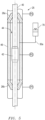
- FIG. 2 depicts a cross sectional schematic view of the RCD 24 according to an embodiment.
- the RCD 24 as shown has a seal assembly 25 with at least two seal elements 12 in the form of stripper rubbers 26.
- the seal assembly may further include relief valve(s) 60 and/or accumulator(s) 70.
- the stripper rubbers 26 are placed in an upper-lower relationship such that there is an upper stripper rubber 26a and a lower stripper rubber 26b.
- the stripper rubbers 26 seal against the tubular 35 and/or piece of oilfield equipment 14/tool joint 42 (as the case may be) when the pressure is greater on the exterior side 27 of the stripper rubber 26 as compared to the pressure on the interior side 29 of the stripper rubber 26.
- fluid may "burp" or seep through the stripper rubber 26 at the interface between the stripper rubber 26 and the tubular 35/tool joint 14.
- stripper rubbers 26 may face outward (exterior side 27 outside the pressure control chamber 44) as represented in Figure 2 . In alternative embodiments, stripper rubbers 26 may face inward (exterior side 27 defining the pressure control chamber 44) as represented in Figure 3 .
- the piece of oilfield equipment 14 entering and/or exiting the RCD 24 is a drill string 40 having one or more tool joints 42 on the drill string 40.
- the tool joints 42 have a larger outer diameter than the drill pipe of the drill string 40. Further, the tool joints 42 may increase, and/or decrease, in size as the oilfield equipment 14 is run into or out of the wellbore 16 (as shown in Figure 1 ).
- a pressure control chamber 44 is defined by and located between the upper stripper rubber 26a and the lower stripper rubber 26b and within bearing assembly 46. As a tool joint 42 enters the pressure control chamber 44, fluid within the pressure control chamber is displaced out of the pressure control chamber 44. The fluid may be displaced through the stripper rubbers 26a and/or 26b, and or along a flow path 50a,b,c and/or d (shown schematically) and the like.
- the excessive pressure differential could result from tool joints 42 of greater volume displacing or bleeding a volume of fluid from the intermediate pressure control chamber 44 through a stripper rubber 26 and, successively, as the tool joint 42 vacates the intermediate pressure control chamber 44 there is now a lesser total volume of fluid within the pressure control chamber 44, causing a reduction in pressure P2 or suction (as compared to the pressure P1 or P3).
- Such may cause an increased friction force between the stripper rubbers 26a and 26b and the oilfield equipment 14 with downward movement of a tool joint 42 causing stripping down on the stripper rubber 26 and upward movement of a tool joint causing upward stripping on the stripper rubber 26.
- various pressure differential accommodation devices are integrated into the seal assembly 25.
- the various pressure accommodation devices may be individual or pluralities of relief valves 60 and/or accumulators 70.
- a relief valves or valves 60 only may be implemented as the pressure differential accommodation device.
- Various combinations of relief valve(s) 60 and accumulator(s) 70 may alternatively be implemented as the pressure differential accommodation device(s).
- the threshold pressure relief values i.e. the threshold pressure at which any respective device will trip or accommodate to relieve a pressure differential
- the threshold pressure relief values of the relief valves 60 and/or accumulators 70 may be selected according to any desirable threshold pressure relief value. Such selection is within the level of skill of one having ordinary skill in the art.
- Flow path(s) 50a,b,c,d etc. (50e and 50f shown in Fig. 3 creating respective upper and lower flow paths to back side of the accumulators) also make part of the pressure differential accommodation devices as the case may be.
- the accumulators may, for example, be plunger type accumulators or have a diaphragm.
- seal assemblies 25 will be discussed below by way of example.
- the stripper rubbers 26 are facing outward.
- the seal assembly 25 includes relief valves 60a and 60b connected respectively via flow paths 50c and 50d as the pressure differential accommodation devices.
- pressure differential accommodation devices For example if the differential pressure between P3 and P1 is such that P3 is higher, as tool joint 42 enters chamber 44 stripping downward or upward, pressure P2 elevates above pressure P1, and fluid bleeds by lower stripper rubber 26b. At the next interval as the tool joint 42 vacates chamber 44, P2 will drop. Next, top relief valve 60a opens at the threshold pressure which will cause P2 to vary.
- the stripper rubbers 26 are facing outward.
- the seal assembly 25 includes one accumulator 70 connected via flow path 50a as the pressure differential accommodation device in combination with the stripper rubbers 26.
- a first adjustment must be made for temperature.
- the accumulator 70 will be charged to first pressure at a first temperature.
- the temperature will stabilize at a second temperature.
- a new, second pressure will be the accumulator pre-charge.
- the accumulator 70 reaches the final depth in the sea, then a new volume will be established based on sea pressure.
- a tool joint 42 is pulled into the chamber 44, then the fluid volume in chamber 44 will increase.
- the volume in accumulator 70 will decrease.
- the pressure in the accumulator increases (assuming the sealing element 12 or stripper rubber 26 did not leak).
- the stripper rubber(s) 26 (or sealing element 12) will act as a relief valve that will open at a threshold relief pressure.
- the stripper rubber(s) 26 can hold a back pressure up to the threshold relief pressure. If the accumulator pressure exceeds the threshold relief pressure, then the stripper rubber(s) 26 will leak.
- the seal assembly 25 includes one accumulator 70 (similar to the accumulator of Figure 5 only having a larger capacity volume in this embodiment) connected via flow path 50a as the pressure differential accommodation device in combination with the stripper rubbers 26.
- a first adjustment must be made for temperature.
- the accumulator 70 will be charged to first pressure at a first temperature.
- the temperature will stabilize at a second temperature.
- a new, second pressure will be the accumulator pre-charge.
- the accumulator 70 reaches the final depth in the sea, then a new volume will be established based on sea pressure.
- the fluid volume in chamber 44 will increase.
- the volume in accumulator 70 will decrease.
- the pressure in the accumulator increases (assuming the sealing element 12 or stripper rubber 26 did not leak).
- the stripper rubber(s) 26 (or sealing element 12) will act as a relief valve that will open at a threshold relief pressure.
- the stripper rubber(s) 26 can hold a back pressure up to the threshold relief pressure. If the accumulator pressure exceeds the threshold relief pressure, then the stripper rubber(s) 26 will leak.
- the stripper rubbers 26 are facing inward.
- the seal assembly 25 includes relief valves 60a and 60b connected respectively via flow paths 50c and 50d as the pressure differential accommodation devices.
- the bottom relief valve 60b may limit the elevation of P2.
- P2 will drop. Fluid may bleed by the upper stripper rubber 26a and bring P2 into equilibrium with P3.
- the top relief valve 60a may limit the elevation of P2.
- P2 will drop. Fluid may bleed by the lower stripper rubber 26b and bring P2 into equilibrium with P1.
- the stripper rubbers 26 are facing outward.
- the seal assembly 25 includes accumulator(s) 70 (each having spring-type plunger 72) connected via flow paths 50a and/or 50b as the pressure differential accommodation device in combination with the stripper rubbers 26.
- accumulator(s) 70 each having spring-type plunger 72
- flow paths 50a and/or 50b as the pressure differential accommodation device in combination with the stripper rubbers 26.
- the volume of fluid displaced by the tool joint 42 may also be taken on by the accumulator as P2 increases, in which case as the tool joint 42 leaves the chamber 44 the chamber 44 may lose fluid.
- P3 greater than P1
- stripping upward or downward the bottom accumulator 70 empty, the top accumulator 70 empty; the tool joint 42 enters the chamber 44 via stripper rubber 26; next, P2 increases; then, the bottom accumulator 70 may take volume of fluid displaced by the tool joint 42; when the tool joint 42 leaves chamber 44, the chamber 44 may lose fluid.
- the seal assembly 25 includes accumulator(s) 70a and 70b (each having spring-type plunger 72) connected via flow paths 50a and/or 50b in combination with relief valves 60a and 60b connected respectively via flow paths 50c and 50d as the pressure differential accommodation device in combination with the stripper rubbers 26.
- the bottom accumulator 70b may be empty; the top accumulator 70a may be empty; as the tool joint 42 enters the chamber 44 via the stripper rubber 26; next, P2 increases; the bottom accumulator may take on the volume of fluid displaced by the tool joint 42; then, the tool joint 42 leaves chamber 44.
- the chamber 44 may lose fluid. If P2 is sufficiently lowered to beyond a threshold pressure in the relief valve, the top relief valve 60a may open.
- the bottom accumulator 70b may be empty; the top accumulator 70a may be empty; as the tool joint 42 enters the chamber 44 via the stripper rubber 26; next, P2 increases; the top accumulator 70a may take on the volume of fluid displaced by the tool joint 42; then, the tool joint 42 leaves chamber 44.
- the chamber 44 may lose fluid. If P2 is sufficiently lowered to beyond a threshold pressure in the relief valve, the bottom relief valve 60b may open.
- the seal assembly 25 includes accumulator(s) 70a and 70b connected via flow paths 50a and/or 50b (and optionally supplied by respective flow paths 50e and 50f) in combination with relief valves 60a and 60b connected respectively via flow paths 50c and 50d as the pressure differential accommodation device in combination with the stripper rubbers 26.
- the differential pressure between P3 and P1 is such that P3 is higher, stripping upward or downward; with the top accumulator 70a empty; the bottom accumulator 70b full; as the tool joint 42 enters the chamber 44 via a stripper rubber 42; next, the top accumulator 70a may take on the volume of fluid displaced by the tool joint 42; if chamber 44 fluid is of sufficiently low pressure, the stripper rubber 26 bleeds/burps. If the chamber 44, P2, develops overpressure beyond a threshold pressure, the bottom relief valve 60b may open.
- the differential pressure between P3 and P1 is such that P1 is higher, stripping upward or downward; with the top accumulator 70a full; the bottom accumulator 70b empty; as the tool joint 42 enters the chamber 44 via a stripper rubber 26; next, the bottom accumulator 70b may take on the volume of fluid displaced by the tool joint 42; if chamber 44 fluid is of sufficiently low pressure, the stripper rubber 26 bleeds/burps. If the chamber 44, P2, develops overpressure beyond a threshold pressure, the top relief valve 60a may open.
- Such a pressure differential accommodation device in one embodiment (see Fig. 9 ) may appear as one or more small orifices 80 near the interface of the bearing assembly 46 and the upper stripper rubber 26a creating a replenishment chamber/path to the chamber 44. In another embodiment (see Figs. 10-11 ) it may appear as a notch or groove 90 formed or made through a portion of the upper stripper rubber 26a. It is to be understood that the embodiments of Figs. 9-11 have been described as being applicable to the upper stripper rubber 26a, however they may be equally applicable to the lower stripper rubber 26b. The embodiments of Figs. 9-11 may be combined with other pressure differential accommodation device(s).
- the pressure differential accommodation device may need to function according to certain critical timing intervals depending upon displacement volumes, speed of tool joint 42 entering and vacating the chamber 44, etc. Accordingly one of ordinary skill in the art may design a respective seal assembly 25 to accommodate the rate of volume displacement.
- bearing assembly 46 has been discussed above as appearing intermediate the upper stripper rubber 26a and the lower stripper rubber 26b. However, it is to be understood that in other embodiments, somewhat as represented in various figures of the drawings, the bearing assembly(ies) 46 may not appear intermediate and may appear above and/or below the respective upper stripper rubber 26a and the lower stripper rubber 26b.
- the RCD 24 may have any number of elements which seal against a tubular 35 inserted through its interior.
- These seal elements 12 may include one or more passive seals or stripper rubbers 26.
- These seal elements 12 may include one or more active seals.
- These seal elements 12 may include only passive seals (stripper rubbers) or only active seals.
- the stripper rubbers 26 may be arranged such that multiple stripper rubbers are stacked to provide contingency pressure sealing from below and/or from above. For example, two stripper rubbers 26 may be arranged to provide pressure sealing from below, and a third stripper rubber 26 arranged to provide pressure sealing from above. Any other combination and arrangement of such seals are contemplated.
- sensor 23 (see Fig. 1 ) to monitor the pressure within chamber 44 enables precise control of this pressure to be accomplished.
- Additional sensors may be positioned such that the pressure immediately above the upper stripper rubber 26a and/or pressure immediately below lower stripper rubber 26b may be monitored.
- One or more pressure control valves may be used in order to bleed pressure into and/or out of chamber 44; these pressure control valves may be actuated using controller 30. The use of such pressure control valves enables (in some circumstances) the path of pressure bleeding to be selected.
- any change in the pressure within chamber 44 may be compensated by a user-selected routing of pressure bleed between chamber 44 and either the zone above upper stripper rubber 26a or the zone below lower stripper rubber 26b. This would be advantageous in ensuring that fluids in the wellbore (i.e. below lower stripper rubber 26b) are not inadvertently routed via chamber 44 to the zone above upper stripper rubber 26a.
- one or more relief valves 60 may also be incorporated in order to ensure that critical overpressure or underpressure conditions do not occur.
- the pressure above upper stripper rubber 26a may be controlled. This may be achieved by the riser containing a suitable fluid of appropriate density and/or the application of pressure at surface to the fluid within the riser. The pressure above upper stripper rubber 26a may therefore be controlled such that this pressure is approximately equal to or somewhat greater than the pressure below the lower stripper rubber.
- an embodiment of the configurations described herein may include only one relief valve 60 and/or only one control valve and/or only one accumulator 70.
- the single relief valve/control valve/accumulator may be connected between the zone below lower stripper rubber 26b and chamber 44. This would, advantageously, minimize the risk of wellbore fluids being communicated via chamber 44 to the riser.
- the embodiments described may also be used in non-rotating pressure control devices.
- Stripper rubber assembly 100 may be configured such that, in use, a change in pressure within chamber 44 may urge stripper rubber 26 to move axially. In this way, the volume of chamber 44 may be maintained substantially constant despite the passage of tool joint 42 (not shown).
- Stripper rubber 26 is mounted via a mounting assembly 102 so as to be positionally biased in a downward direction by biasing member 104.
- biasing member 104 may be a spring.
- the biasing of stripper rubber 26 may be achieved through a pressurized fluid acting upon mounting assembly 102. Because stripper rubber 26 may move axially, a seal 106 may be utilized between mounting assembly 102 and the interior surface 108 of external member 110. External member 110 may be part of housing or bearing assembly, or any other member suitable for sealing against.
- Stripper rubber assembly 100 is shown with stripper rubber 26 facing downward and biased downward. However, it is also contemplated that stripper rubber assembly 100 may be mounted inverted with stripper rubber 26 facing upward and biased upward.
- Stripper rubber assembly 200 may also be configured such that, in use, a change in pressure within chamber 44 may urge stripper rubber 26 to move axially. In this way, the volume of chamber 44 may be maintained substantially constant despite the passage of tool joint 42 (not shown).
- Stripper rubber 26 is mounted via a mounting assembly 202 so as to be positionally biased in an upward direction by biasing member 204.
- biasing member 204 may be a spring.
- the biasing of stripper rubber 26 may be achieved through a pressurized fluid acting upon mounting assembly 202. Because stripper rubber 26 may move axially, a seal 206 may be utilized between mounting assembly 202 and the interior surface 208 of external member 210. External member 210 may be part of a housing or bearing assembly, or any other member suitable for sealing against.
- Stripper rubber assembly 200 is shown with stripper rubber 26 facing downward and biased upward. However, it is also contemplated that stripper rubber assembly 100 may be mounted inverted with stripper rubber 26 facing upward and biased downward.
- one or more of the stripper rubbers 26a and 26b shown in Fig. 2 may be configured using stripper rubber assembly 100 and/or stripper rubber assembly 200, such that either or both stripper rubbers 26a and 26b are biased axially away from each other.
- stripper rubber assembly 100 and/or stripper rubber assembly 200 such that either or both stripper rubbers 26a and 26b are biased axially away from each other.
- biasing members 104/204 may be selected such that when the pressure within chamber 44 reaches a selected value, one or both stripper rubbers 26a and 26b will move axially such that the stripper rubbers 26a and 26b momentarily become closer together. This results in a momentary decrease in the size of chamber 44, which alleviates the drop in pressure within chamber 44. With the entry of a second tool joint 42 into the chamber 44, the available volume for the fluid trapped within chamber 44 again decreases, thereby resulting in a momentary rise in pressure within chamber 44.
- This rise in pressure may be accommodated by either the "burping" phenomenon described above, and/or axial movement of one or both stripper rubbers 26a, 26b, such that stripper rubbers 26a, 26b become axially further apart, which is promoted by biasing members 104/204.
- the exit of the second tool joint 42 may be accompanied by axial movement of one or both stripper rubbers 26a, 26b such that they become axially closer together. In this way, pressure fluctuations within chamber 44may be accommodated without the need to vent fluid either out of or into chamber 44.
- one or more of the stripper rubbers 26a and 26b shown in Fig. 3 may be configured using stripper rubber assembly 100 and/or stripper rubber assembly 200, such that either or both stripper rubbers 26a and 26b are biased axially towards each other.
- relief valves 60a and 60b and/or accumulators 70a and 70b may be omitted, such that chamber 44 is without any ports.
- the fluid within chamber 44 is trapped, and therefore the pressure within chamber 44 rises. This pressure acts on both stripper rubbers 26a and 26b and therefore also acts against biasing members 104/204.
- biasing members 104/204 may be selected such that when the pressure within chamber 44 reaches a selected value, one or both stripper rubbers 26a and 26b will move axially such that the stripper rubbers 26a and 26b momentarily become further apart. This results in a momentary increase in the size of chamber 44, which alleviates the rise in pressure within chamber 44. Then, when tool joint 42 exits chamber 44, the available volume for the fluid within chamber 44 increases, thereby creating a momentary decrease in pressure within chamber 44.
- one or more of the pressure relief mechanisms described herein may be utilized in combination with one or more stripper rubber assemblies 100/200 as described above.
Landscapes
- Geology (AREA)
- Life Sciences & Earth Sciences (AREA)
- Engineering & Computer Science (AREA)
- Mining & Mineral Resources (AREA)
- Environmental & Geological Engineering (AREA)
- Fluid Mechanics (AREA)
- Physics & Mathematics (AREA)
- General Life Sciences & Earth Sciences (AREA)
- Geochemistry & Mineralogy (AREA)
- Earth Drilling (AREA)
- Gasket Seals (AREA)
- Sealing Devices (AREA)
- Heating, Cooling, Or Curing Plastics Or The Like In General (AREA)
- Motor Or Generator Frames (AREA)
- Braking Arrangements (AREA)
Claims (4)
- Appareil de contrôle de pression de champ pétrolifère (22), comprenant :un élément d'étanchéité supérieur (26a) configuré pour assurer l'étanchéité autour d'un train de tiges (40), dans lequel l'élément d'étanchéité supérieur (26a) comprend un presse-étoupe configuré pour assurer l'étanchéité autour du train de tiges (40) lorsque la pression sur un côté extérieur (27) du presse-étoupe est supérieure à la pression sur un côté intérieur (29) du presse-étoupe, le côté extérieur du presse-étoupe de l'élément d'étanchéité supérieur (26a) étant orienté dans un premier sens axial ;un élément d'étanchéité inférieur (26b) configuré pour assurer l'étanchéité autour du train de tiges (40), dans lequel l'élément d'étanchéité inférieur (26b) comprend un presse-étoupe configuré pour assurer l'étanchéité autour du train de tiges (40) lorsque la pression sur un côté extérieur (27) du presse-étoupe est supérieure à la pression sur un côté intérieur (29) du presse-étoupe, le côté extérieur du presse-étoupe de l'élément d'étanchéité inférieur (26a) étant orienté dans un deuxième sens axial opposé au premier sens axial ;une chambre (44) définie par et située entre les éléments d'étanchéité supérieur et inférieur (26a, 26b) ; etau moins un dispositif d'adaptation de pression différentielle (60, 70) en communication fluidique avec la chambre (44),dans lequel l'au moins un dispositif d'adaptation de pression différentielle (60, 70) est configuré pour compenser un premier changement d'une pression à l'intérieur de la chambre (44) provoqué par l'entrée d'un raccord de tige (42) sur le train de tiges (40) dans la chambre (44) via un des éléments d'étanchéité supérieur et inférieur (26a, 26b), et pour compenser un deuxième changement de la pression à l'intérieur de la chambre (44) provoqué par la sortie du raccord de tige (42) de la chambre (44) via l'autre des éléments d'étanchéité supérieur et inférieur (26a, 26b),dans lequel l'au moins un dispositif d'adaptation de pression différentielle (60, 70) comprend une soupape de décharge (60) configurée pour être en communication fluidique avec une colonne montante, ou, dans le cas d'opérations de forage sans colonne montante, la mer au-dessus de l'élément d'étanchéité supérieur (26a).
- Appareil de contrôle de pression de champ pétrolifère (22) selon la revendication 1, dans lequel un fluide est acheminé à travers la soupape de décharge (60) entre la région et la chambre (44) afin de compenser les premier et deuxième changements de la pression à l'intérieur de la chambre (44).
- Appareil de contrôle de pression de champ pétrolifère (22) selon la revendication 2, dans lequel le fluide s'écoule dans la chambre (44), ou
dans lequel le fluide s'écoule hors de la chambre (44). - Appareil de contrôle de pression de champ pétrolifère (22) selon la revendication 1, dans lequel l'au moins un dispositif d'adaptation de pression différentielle (60, 70) comprend un accumulateur (70).
Applications Claiming Priority (2)
| Application Number | Priority Date | Filing Date | Title |
|---|---|---|---|
| US201161545100P | 2011-10-07 | 2011-10-07 | |
| PCT/US2012/059004 WO2013052830A2 (fr) | 2011-10-07 | 2012-10-05 | Assemblages de joint d'étanchéité dans des dispositifs de commande tournants sous-marins |
Publications (2)
| Publication Number | Publication Date |
|---|---|
| EP2764198A2 EP2764198A2 (fr) | 2014-08-13 |
| EP2764198B1 true EP2764198B1 (fr) | 2023-05-31 |
Family
ID=47116379
Family Applications (1)
| Application Number | Title | Priority Date | Filing Date |
|---|---|---|---|
| EP12780583.6A Active EP2764198B1 (fr) | 2011-10-07 | 2012-10-05 | Assemblages de joint d'étanchéité dans des dispositifs de commande tournants sous-marins |
Country Status (6)
| Country | Link |
|---|---|
| US (1) | US10000988B2 (fr) |
| EP (1) | EP2764198B1 (fr) |
| AU (2) | AU2012318451B2 (fr) |
| BR (1) | BR112014008300B1 (fr) |
| CA (1) | CA2850500C (fr) |
| WO (1) | WO2013052830A2 (fr) |
Families Citing this family (11)
| Publication number | Priority date | Publication date | Assignee | Title |
|---|---|---|---|---|
| US8875798B2 (en) * | 2009-04-27 | 2014-11-04 | National Oilwell Varco, L.P. | Wellsite replacement system and method for using same |
| US9022126B2 (en) * | 2009-07-01 | 2015-05-05 | National Oilwell Varco, L.P. | Wellsite equipment replacement system and method for using same |
| US9080427B2 (en) * | 2011-12-02 | 2015-07-14 | General Electric Company | Seabed well influx control system |
| CN103470201B (zh) | 2012-06-07 | 2017-05-10 | 通用电气公司 | 流体控制系统 |
| US9441444B2 (en) | 2013-09-13 | 2016-09-13 | National Oilwell Varco, L.P. | Modular subsea stripper packer and method of using same |
| GB2525396B (en) * | 2014-04-22 | 2020-10-07 | Managed Pressure Operations | Method of operating a drilling system |
| CA2942840C (fr) * | 2014-04-30 | 2018-03-27 | Weatherford Technology Holdings, Llc | Montage d'element d'etancheite |
| US10612336B2 (en) | 2014-08-21 | 2020-04-07 | Halliburton Energy Services, Inc. | Rotating control device |
| US9835005B2 (en) * | 2014-12-31 | 2017-12-05 | Cameron International Corporation | Energized seal system and method |
| NL2015363B1 (en) * | 2015-08-28 | 2017-03-20 | Itrec Bv | Sealing and controlling of fluid pressure in an annular fluid passageway in a wellbore related process. |
| US20230035783A1 (en) * | 2021-07-28 | 2023-02-02 | Benton Frederick Baugh | Method for a 20 KSI BOP Stack with shared differential |
Citations (3)
| Publication number | Priority date | Publication date | Assignee | Title |
|---|---|---|---|---|
| WO1999049173A1 (fr) * | 1998-03-27 | 1999-09-30 | Hydril Company | Deflecteur sous-marin rotatif |
| WO2001069034A2 (fr) * | 2000-03-14 | 2001-09-20 | Weatherford/Lamb, Inc. | Systeme de mise en circulation de fluide pour puits de forage |
| EP2208855A2 (fr) * | 2009-01-15 | 2010-07-21 | Weatherford Lamb, Inc. | Procédé et dispositif sous-marin de contrôle rotatif disposé à l'intérieur d'une colonne montante |
Family Cites Families (9)
| Publication number | Priority date | Publication date | Assignee | Title |
|---|---|---|---|---|
| US3387851A (en) * | 1966-01-12 | 1968-06-11 | Shaffer Tool Works | Tandem stripper sealing apparatus |
| US3583480A (en) * | 1970-06-10 | 1971-06-08 | Regan Forge & Eng Co | Method of providing a removable packing insert in a subsea stationary blowout preventer apparatus |
| US4441551A (en) * | 1981-10-15 | 1984-04-10 | Biffle Morris S | Modified rotating head assembly for rotating blowout preventors |
| US6202753B1 (en) * | 1998-12-21 | 2001-03-20 | Benton F. Baugh | Subsea accumulator and method of operation of same |
| US7779903B2 (en) | 2002-10-31 | 2010-08-24 | Weatherford/Lamb, Inc. | Solid rubber packer for a rotating control device |
| GB0417543D0 (en) * | 2004-08-06 | 2004-09-08 | Stacey Oil Services Ltd | Improvements in or relating to diverter heads |
| US20090283279A1 (en) * | 2005-04-25 | 2009-11-19 | Schlumberger Technology Corporation | Zonal isolation system |
| US8347983B2 (en) * | 2009-07-31 | 2013-01-08 | Weatherford/Lamb, Inc. | Drilling with a high pressure rotating control device |
| US8522864B1 (en) * | 2011-05-27 | 2013-09-03 | James Otis Miller | Stripper blow out preventer for small diameter oil field tubing or small diameter polished rods |
-
2012
- 2012-10-05 EP EP12780583.6A patent/EP2764198B1/fr active Active
- 2012-10-05 CA CA2850500A patent/CA2850500C/fr active Active
- 2012-10-05 WO PCT/US2012/059004 patent/WO2013052830A2/fr not_active Ceased
- 2012-10-05 US US13/645,738 patent/US10000988B2/en active Active
- 2012-10-05 AU AU2012318451A patent/AU2012318451B2/en active Active
- 2012-10-05 BR BR112014008300-2A patent/BR112014008300B1/pt active IP Right Grant
-
2016
- 2016-08-02 AU AU2016210618A patent/AU2016210618B2/en active Active
Patent Citations (3)
| Publication number | Priority date | Publication date | Assignee | Title |
|---|---|---|---|---|
| WO1999049173A1 (fr) * | 1998-03-27 | 1999-09-30 | Hydril Company | Deflecteur sous-marin rotatif |
| WO2001069034A2 (fr) * | 2000-03-14 | 2001-09-20 | Weatherford/Lamb, Inc. | Systeme de mise en circulation de fluide pour puits de forage |
| EP2208855A2 (fr) * | 2009-01-15 | 2010-07-21 | Weatherford Lamb, Inc. | Procédé et dispositif sous-marin de contrôle rotatif disposé à l'intérieur d'une colonne montante |
Also Published As
| Publication number | Publication date |
|---|---|
| CA2850500A1 (fr) | 2013-04-11 |
| WO2013052830A2 (fr) | 2013-04-11 |
| AU2016210618B2 (en) | 2017-07-20 |
| US20130192847A1 (en) | 2013-08-01 |
| AU2012318451A1 (en) | 2014-05-01 |
| WO2013052830A3 (fr) | 2014-01-16 |
| US10000988B2 (en) | 2018-06-19 |
| EP2764198A2 (fr) | 2014-08-13 |
| BR112014008300A8 (pt) | 2018-04-03 |
| AU2012318451B2 (en) | 2016-05-26 |
| BR112014008300A2 (pt) | 2017-04-18 |
| BR112014008300B1 (pt) | 2021-02-17 |
| AU2016210618A1 (en) | 2016-08-18 |
| CA2850500C (fr) | 2019-02-26 |
Similar Documents
| Publication | Publication Date | Title |
|---|---|---|
| EP2764198B1 (fr) | Assemblages de joint d'étanchéité dans des dispositifs de commande tournants sous-marins | |
| US9708854B2 (en) | Device and method for drilling with continuous tool rotation and continuous drilling fluid supply | |
| EP1270870B1 (fr) | Appareil pour tester un obturateur anti-éruption | |
| US7665515B2 (en) | Casing and drill pipe filling and circulating method | |
| US8403034B2 (en) | Device and method for maintaining constant pressure on, and flow drill fluid, in a drill string | |
| AU2010366660B2 (en) | Subsea pressure control system | |
| US10161219B2 (en) | Gravel pack-circulating sleeve with hydraulic lock | |
| GB2399112A (en) | Method and apparatus for connecting tubulars while drilling | |
| US9187970B2 (en) | Wellbore isolation devices and methods of use to prevent pump offs | |
| CN103132956B (zh) | 海床井流入量控制系统 | |
| CA2942840C (fr) | Montage d'element d'etancheite | |
| GB2498075A (en) | Vertical Subsea Tree Assembly Control | |
| AU2018293286A1 (en) | Valve system | |
| RU2498053C1 (ru) | Способ одновременно-раздельной добычи углеводородов гарипова и установка для его реализации |
Legal Events
| Date | Code | Title | Description |
|---|---|---|---|
| PUAI | Public reference made under article 153(3) epc to a published international application that has entered the european phase |
Free format text: ORIGINAL CODE: 0009012 |
|
| 17P | Request for examination filed |
Effective date: 20140507 |
|
| AK | Designated contracting states |
Kind code of ref document: A2 Designated state(s): AL AT BE BG CH CY CZ DE DK EE ES FI FR GB GR HR HU IE IS IT LI LT LU LV MC MK MT NL NO PL PT RO RS SE SI SK SM TR |
|
| DAX | Request for extension of the european patent (deleted) | ||
| RAP1 | Party data changed (applicant data changed or rights of an application transferred) |
Owner name: WEATHERFORD TECHNOLOGY HOLDINGS, LLC |
|
| STAA | Information on the status of an ep patent application or granted ep patent |
Free format text: STATUS: EXAMINATION IS IN PROGRESS |
|
| 17Q | First examination report despatched |
Effective date: 20161205 |
|
| 111Z | Information provided on other rights and legal means of execution |
Free format text: AL AT BE BG CH CY CZ DE DK EE ES FI FR GB GR HR HU IE IS IT LT LU LV MC MK MT NL NO PL PT RO RS SE SI SK SM TR AL AT BE BG CH CY CZ DE DK EE ES FI FR GB GR HR HU IE IS IT LT LU LV MC MK MT NL NO PL PT RO RS SE SI SK SM TR Effective date: 20200511 |
|
| R11X | Information provided on other rights and legal means of execution (corrected) |
Free format text: AL AT BE BG CH CY CZ DE DK EE ES FI FR GB GR HR HU IE IS IT LT LU LV MC MK MT NL NO PL PT RO RS SE SI SK SM TR Effective date: 20200511 |
|
| 111Z | Information provided on other rights and legal means of execution |
Free format text: AL AT BE BG CH CY CZ DE DK EE ES FI FR GB GR HR HU IE IS IT LT LU LV MC MK MT NL NO PL PT RO RS SE SI SK SM TR AL AT BE BG CH CY CZ DE DK EE ES FI FR GB GR HR HU IE IS IT LT LU LV MC MK MT NL NO PL PT RO RS SE SI SK SM TR Effective date: 20200511 |
|
| GRAP | Despatch of communication of intention to grant a patent |
Free format text: ORIGINAL CODE: EPIDOSNIGR1 |
|
| STAA | Information on the status of an ep patent application or granted ep patent |
Free format text: STATUS: GRANT OF PATENT IS INTENDED |
|
| INTG | Intention to grant announced |
Effective date: 20221221 |
|
| RIN1 | Information on inventor provided before grant (corrected) |
Inventor name: CHAMBERS, JAMES W. Inventor name: HARRALL, SIMON J. Inventor name: BARRY, ANDREW A. W. Inventor name: WAGONER, DANNY W. Inventor name: BAILEY, THOMAS F. |
|
| GRAS | Grant fee paid |
Free format text: ORIGINAL CODE: EPIDOSNIGR3 |
|
| GRAA | (expected) grant |
Free format text: ORIGINAL CODE: 0009210 |
|
| STAA | Information on the status of an ep patent application or granted ep patent |
Free format text: STATUS: THE PATENT HAS BEEN GRANTED |
|
| AK | Designated contracting states |
Kind code of ref document: B1 Designated state(s): AL AT BE BG CH CY CZ DE DK EE ES FI FR GB GR HR HU IE IS IT LI LT LU LV MC MK MT NL NO PL PT RO RS SE SI SK SM TR |
|
| REG | Reference to a national code |
Ref country code: GB Ref legal event code: FG4D Ref country code: CH Ref legal event code: EP |
|
| REG | Reference to a national code |
Ref country code: DE Ref legal event code: R096 Ref document number: 602012079608 Country of ref document: DE |
|
| REG | Reference to a national code |
Ref country code: AT Ref legal event code: REF Ref document number: 1571010 Country of ref document: AT Kind code of ref document: T Effective date: 20230615 |
|
| REG | Reference to a national code |
Ref country code: IE Ref legal event code: FG4D |
|
| REG | Reference to a national code |
Ref country code: LT Ref legal event code: MG9D |
|
| REG | Reference to a national code |
Ref country code: NO Ref legal event code: T2 Effective date: 20230531 |
|
| REG | Reference to a national code |
Ref country code: NL Ref legal event code: MP Effective date: 20230531 |
|
| REG | Reference to a national code |
Ref country code: AT Ref legal event code: MK05 Ref document number: 1571010 Country of ref document: AT Kind code of ref document: T Effective date: 20230531 |
|
| PG25 | Lapsed in a contracting state [announced via postgrant information from national office to epo] |
Ref country code: SE Free format text: LAPSE BECAUSE OF FAILURE TO SUBMIT A TRANSLATION OF THE DESCRIPTION OR TO PAY THE FEE WITHIN THE PRESCRIBED TIME-LIMIT Effective date: 20230531 Ref country code: ES Free format text: LAPSE BECAUSE OF FAILURE TO SUBMIT A TRANSLATION OF THE DESCRIPTION OR TO PAY THE FEE WITHIN THE PRESCRIBED TIME-LIMIT Effective date: 20230531 Ref country code: AT Free format text: LAPSE BECAUSE OF FAILURE TO SUBMIT A TRANSLATION OF THE DESCRIPTION OR TO PAY THE FEE WITHIN THE PRESCRIBED TIME-LIMIT Effective date: 20230531 |
|
| P01 | Opt-out of the competence of the unified patent court (upc) registered |
Effective date: 20230922 |
|
| PG25 | Lapsed in a contracting state [announced via postgrant information from national office to epo] |
Ref country code: RS Free format text: LAPSE BECAUSE OF FAILURE TO SUBMIT A TRANSLATION OF THE DESCRIPTION OR TO PAY THE FEE WITHIN THE PRESCRIBED TIME-LIMIT Effective date: 20230531 Ref country code: PL Free format text: LAPSE BECAUSE OF FAILURE TO SUBMIT A TRANSLATION OF THE DESCRIPTION OR TO PAY THE FEE WITHIN THE PRESCRIBED TIME-LIMIT Effective date: 20230531 Ref country code: NL Free format text: LAPSE BECAUSE OF FAILURE TO SUBMIT A TRANSLATION OF THE DESCRIPTION OR TO PAY THE FEE WITHIN THE PRESCRIBED TIME-LIMIT Effective date: 20230531 Ref country code: LV Free format text: LAPSE BECAUSE OF FAILURE TO SUBMIT A TRANSLATION OF THE DESCRIPTION OR TO PAY THE FEE WITHIN THE PRESCRIBED TIME-LIMIT Effective date: 20230531 Ref country code: LT Free format text: LAPSE BECAUSE OF FAILURE TO SUBMIT A TRANSLATION OF THE DESCRIPTION OR TO PAY THE FEE WITHIN THE PRESCRIBED TIME-LIMIT Effective date: 20230531 Ref country code: IS Free format text: LAPSE BECAUSE OF FAILURE TO SUBMIT A TRANSLATION OF THE DESCRIPTION OR TO PAY THE FEE WITHIN THE PRESCRIBED TIME-LIMIT Effective date: 20230930 Ref country code: HR Free format text: LAPSE BECAUSE OF FAILURE TO SUBMIT A TRANSLATION OF THE DESCRIPTION OR TO PAY THE FEE WITHIN THE PRESCRIBED TIME-LIMIT Effective date: 20230531 Ref country code: GR Free format text: LAPSE BECAUSE OF FAILURE TO SUBMIT A TRANSLATION OF THE DESCRIPTION OR TO PAY THE FEE WITHIN THE PRESCRIBED TIME-LIMIT Effective date: 20230901 |
|
| PG25 | Lapsed in a contracting state [announced via postgrant information from national office to epo] |
Ref country code: FI Free format text: LAPSE BECAUSE OF FAILURE TO SUBMIT A TRANSLATION OF THE DESCRIPTION OR TO PAY THE FEE WITHIN THE PRESCRIBED TIME-LIMIT Effective date: 20230531 |
|
| PG25 | Lapsed in a contracting state [announced via postgrant information from national office to epo] |
Ref country code: SK Free format text: LAPSE BECAUSE OF FAILURE TO SUBMIT A TRANSLATION OF THE DESCRIPTION OR TO PAY THE FEE WITHIN THE PRESCRIBED TIME-LIMIT Effective date: 20230531 |
|
| PG25 | Lapsed in a contracting state [announced via postgrant information from national office to epo] |
Ref country code: SM Free format text: LAPSE BECAUSE OF FAILURE TO SUBMIT A TRANSLATION OF THE DESCRIPTION OR TO PAY THE FEE WITHIN THE PRESCRIBED TIME-LIMIT Effective date: 20230531 Ref country code: SK Free format text: LAPSE BECAUSE OF FAILURE TO SUBMIT A TRANSLATION OF THE DESCRIPTION OR TO PAY THE FEE WITHIN THE PRESCRIBED TIME-LIMIT Effective date: 20230531 Ref country code: RO Free format text: LAPSE BECAUSE OF FAILURE TO SUBMIT A TRANSLATION OF THE DESCRIPTION OR TO PAY THE FEE WITHIN THE PRESCRIBED TIME-LIMIT Effective date: 20230531 Ref country code: PT Free format text: LAPSE BECAUSE OF FAILURE TO SUBMIT A TRANSLATION OF THE DESCRIPTION OR TO PAY THE FEE WITHIN THE PRESCRIBED TIME-LIMIT Effective date: 20231002 Ref country code: EE Free format text: LAPSE BECAUSE OF FAILURE TO SUBMIT A TRANSLATION OF THE DESCRIPTION OR TO PAY THE FEE WITHIN THE PRESCRIBED TIME-LIMIT Effective date: 20230531 Ref country code: DK Free format text: LAPSE BECAUSE OF FAILURE TO SUBMIT A TRANSLATION OF THE DESCRIPTION OR TO PAY THE FEE WITHIN THE PRESCRIBED TIME-LIMIT Effective date: 20230531 Ref country code: CZ Free format text: LAPSE BECAUSE OF FAILURE TO SUBMIT A TRANSLATION OF THE DESCRIPTION OR TO PAY THE FEE WITHIN THE PRESCRIBED TIME-LIMIT Effective date: 20230531 |
|
| REG | Reference to a national code |
Ref country code: DE Ref legal event code: R097 Ref document number: 602012079608 Country of ref document: DE |
|
| PLBE | No opposition filed within time limit |
Free format text: ORIGINAL CODE: 0009261 |
|
| STAA | Information on the status of an ep patent application or granted ep patent |
Free format text: STATUS: NO OPPOSITION FILED WITHIN TIME LIMIT |
|
| REG | Reference to a national code |
Ref country code: DE Ref legal event code: R119 Ref document number: 602012079608 Country of ref document: DE |
|
| PG25 | Lapsed in a contracting state [announced via postgrant information from national office to epo] |
Ref country code: SI Free format text: LAPSE BECAUSE OF FAILURE TO SUBMIT A TRANSLATION OF THE DESCRIPTION OR TO PAY THE FEE WITHIN THE PRESCRIBED TIME-LIMIT Effective date: 20230531 |
|
| 26N | No opposition filed |
Effective date: 20240301 |
|
| PG25 | Lapsed in a contracting state [announced via postgrant information from national office to epo] |
Ref country code: SI Free format text: LAPSE BECAUSE OF FAILURE TO SUBMIT A TRANSLATION OF THE DESCRIPTION OR TO PAY THE FEE WITHIN THE PRESCRIBED TIME-LIMIT Effective date: 20230531 Ref country code: IT Free format text: LAPSE BECAUSE OF FAILURE TO SUBMIT A TRANSLATION OF THE DESCRIPTION OR TO PAY THE FEE WITHIN THE PRESCRIBED TIME-LIMIT Effective date: 20230531 Ref country code: MC Free format text: LAPSE BECAUSE OF FAILURE TO SUBMIT A TRANSLATION OF THE DESCRIPTION OR TO PAY THE FEE WITHIN THE PRESCRIBED TIME-LIMIT Effective date: 20230531 |
|
| REG | Reference to a national code |
Ref country code: CH Ref legal event code: PL |
|
| REG | Reference to a national code |
Ref country code: BE Ref legal event code: MM Effective date: 20231031 |
|
| PG25 | Lapsed in a contracting state [announced via postgrant information from national office to epo] |
Ref country code: LU Free format text: LAPSE BECAUSE OF NON-PAYMENT OF DUE FEES Effective date: 20231005 |
|
| PG25 | Lapsed in a contracting state [announced via postgrant information from national office to epo] |
Ref country code: LU Free format text: LAPSE BECAUSE OF NON-PAYMENT OF DUE FEES Effective date: 20231005 |
|
| PG25 | Lapsed in a contracting state [announced via postgrant information from national office to epo] |
Ref country code: CH Free format text: LAPSE BECAUSE OF NON-PAYMENT OF DUE FEES Effective date: 20231031 |
|
| PG25 | Lapsed in a contracting state [announced via postgrant information from national office to epo] |
Ref country code: FR Free format text: LAPSE BECAUSE OF NON-PAYMENT OF DUE FEES Effective date: 20231031 Ref country code: DE Free format text: LAPSE BECAUSE OF NON-PAYMENT OF DUE FEES Effective date: 20240501 Ref country code: CH Free format text: LAPSE BECAUSE OF NON-PAYMENT OF DUE FEES Effective date: 20231031 |
|
| PG25 | Lapsed in a contracting state [announced via postgrant information from national office to epo] |
Ref country code: BE Free format text: LAPSE BECAUSE OF NON-PAYMENT OF DUE FEES Effective date: 20231031 |
|
| PG25 | Lapsed in a contracting state [announced via postgrant information from national office to epo] |
Ref country code: IE Free format text: LAPSE BECAUSE OF NON-PAYMENT OF DUE FEES Effective date: 20231005 |
|
| PG25 | Lapsed in a contracting state [announced via postgrant information from national office to epo] |
Ref country code: IE Free format text: LAPSE BECAUSE OF NON-PAYMENT OF DUE FEES Effective date: 20231005 |
|
| PG25 | Lapsed in a contracting state [announced via postgrant information from national office to epo] |
Ref country code: BG Free format text: LAPSE BECAUSE OF FAILURE TO SUBMIT A TRANSLATION OF THE DESCRIPTION OR TO PAY THE FEE WITHIN THE PRESCRIBED TIME-LIMIT Effective date: 20230531 |
|
| PG25 | Lapsed in a contracting state [announced via postgrant information from national office to epo] |
Ref country code: BG Free format text: LAPSE BECAUSE OF FAILURE TO SUBMIT A TRANSLATION OF THE DESCRIPTION OR TO PAY THE FEE WITHIN THE PRESCRIBED TIME-LIMIT Effective date: 20230531 |
|
| PG25 | Lapsed in a contracting state [announced via postgrant information from national office to epo] |
Ref country code: CY Free format text: LAPSE BECAUSE OF FAILURE TO SUBMIT A TRANSLATION OF THE DESCRIPTION OR TO PAY THE FEE WITHIN THE PRESCRIBED TIME-LIMIT; INVALID AB INITIO Effective date: 20121005 |
|
| PG25 | Lapsed in a contracting state [announced via postgrant information from national office to epo] |
Ref country code: HU Free format text: LAPSE BECAUSE OF FAILURE TO SUBMIT A TRANSLATION OF THE DESCRIPTION OR TO PAY THE FEE WITHIN THE PRESCRIBED TIME-LIMIT; INVALID AB INITIO Effective date: 20121005 |
|
| PGFP | Annual fee paid to national office [announced via postgrant information from national office to epo] |
Ref country code: GB Payment date: 20250904 Year of fee payment: 14 |
|
| PG25 | Lapsed in a contracting state [announced via postgrant information from national office to epo] |
Ref country code: TR Free format text: LAPSE BECAUSE OF FAILURE TO SUBMIT A TRANSLATION OF THE DESCRIPTION OR TO PAY THE FEE WITHIN THE PRESCRIBED TIME-LIMIT Effective date: 20230531 |
|
| PGFP | Annual fee paid to national office [announced via postgrant information from national office to epo] |
Ref country code: NO Payment date: 20251009 Year of fee payment: 14 |