EP2764218B1 - Moteur à combustion interne à soupape rotative - Google Patents
Moteur à combustion interne à soupape rotative Download PDFInfo
- Publication number
- EP2764218B1 EP2764218B1 EP12779146.5A EP12779146A EP2764218B1 EP 2764218 B1 EP2764218 B1 EP 2764218B1 EP 12779146 A EP12779146 A EP 12779146A EP 2764218 B1 EP2764218 B1 EP 2764218B1
- Authority
- EP
- European Patent Office
- Prior art keywords
- valve
- rotary valve
- cylinder
- passageway
- combustion chamber
- Prior art date
- Legal status (The legal status is an assumption and is not a legal conclusion. Google has not performed a legal analysis and makes no representation as to the accuracy of the status listed.)
- Active
Links
Images


Classifications
-
- F—MECHANICAL ENGINEERING; LIGHTING; HEATING; WEAPONS; BLASTING
- F01—MACHINES OR ENGINES IN GENERAL; ENGINE PLANTS IN GENERAL; STEAM ENGINES
- F01L—CYCLICALLY OPERATING VALVES FOR MACHINES OR ENGINES
- F01L7/00—Rotary or oscillatory slide valve-gear or valve arrangements
- F01L7/02—Rotary or oscillatory slide valve-gear or valve arrangements with cylindrical, sleeve, or part-annularly shaped valves
- F01L7/021—Rotary or oscillatory slide valve-gear or valve arrangements with cylindrical, sleeve, or part-annularly shaped valves with one rotary valve
- F01L7/024—Cylindrical valves comprising radial inlet and axial outlet or axial inlet and radial outlet
-
- F—MECHANICAL ENGINEERING; LIGHTING; HEATING; WEAPONS; BLASTING
- F01—MACHINES OR ENGINES IN GENERAL; ENGINE PLANTS IN GENERAL; STEAM ENGINES
- F01L—CYCLICALLY OPERATING VALVES FOR MACHINES OR ENGINES
- F01L7/00—Rotary or oscillatory slide valve-gear or valve arrangements
- F01L7/02—Rotary or oscillatory slide valve-gear or valve arrangements with cylindrical, sleeve, or part-annularly shaped valves
- F01L7/021—Rotary or oscillatory slide valve-gear or valve arrangements with cylindrical, sleeve, or part-annularly shaped valves with one rotary valve
- F01L7/025—Cylindrical valves comprising radial inlet and side outlet or side inlet and radial outlet
-
- F—MECHANICAL ENGINEERING; LIGHTING; HEATING; WEAPONS; BLASTING
- F01—MACHINES OR ENGINES IN GENERAL; ENGINE PLANTS IN GENERAL; STEAM ENGINES
- F01L—CYCLICALLY OPERATING VALVES FOR MACHINES OR ENGINES
- F01L7/00—Rotary or oscillatory slide valve-gear or valve arrangements
- F01L7/10—Rotary or oscillatory slide valve-gear or valve arrangements with valves of other specific shape, e.g. spherical
-
- F—MECHANICAL ENGINEERING; LIGHTING; HEATING; WEAPONS; BLASTING
- F01—MACHINES OR ENGINES IN GENERAL; ENGINE PLANTS IN GENERAL; STEAM ENGINES
- F01L—CYCLICALLY OPERATING VALVES FOR MACHINES OR ENGINES
- F01L7/00—Rotary or oscillatory slide valve-gear or valve arrangements
- F01L7/16—Sealing or packing arrangements specially therefor
-
- F—MECHANICAL ENGINEERING; LIGHTING; HEATING; WEAPONS; BLASTING
- F01—MACHINES OR ENGINES IN GENERAL; ENGINE PLANTS IN GENERAL; STEAM ENGINES
- F01L—CYCLICALLY OPERATING VALVES FOR MACHINES OR ENGINES
- F01L7/00—Rotary or oscillatory slide valve-gear or valve arrangements
- F01L7/18—Component parts, details, or accessories not provided for in preceding subgroups of this group
-
- F—MECHANICAL ENGINEERING; LIGHTING; HEATING; WEAPONS; BLASTING
- F02—COMBUSTION ENGINES; HOT-GAS OR COMBUSTION-PRODUCT ENGINE PLANTS
- F02B—INTERNAL-COMBUSTION PISTON ENGINES; COMBUSTION ENGINES IN GENERAL
- F02B2275/00—Other engines, components or details, not provided for in other groups of this subclass
- F02B2275/22—Side valves
Definitions
- the present invention relates to internal combustion engines in which the control of the intake and exhaust of combustion gases is achieved by means of a rotary valve.
- Rotary valves are known, for example in the applicant's co-pending application No. GB 2467947A .
- Rotary valve engines are known to have problems of sealing as there is a conflict between minimising the clearances between the relatively rotating bodies, which improves efficiency, but runs the increasing risk of overheating and seizing.
- Attempts have been made for many years to make a commercially acceptable engine utilising rotary valves, notably by Aspin, but these have mostly been unsuccessful.
- DE 4217608 A1 and DE 4040936 A1 this conflict is recognised and attempts to solve the problem are made by providing complex cooling arrangements or simply saying the problem is solved by using suitable materials.
- larger than desired clearances are provided to reduce the risk of seizing, at the cost of reducing the efficiency of the engine and increased emissions.
- the present invention seeks to provide an improved internal combustion engine of light weight and low cost by utilising the inherent simplicity of a rotary valve.
- a rotary valve internal combustion engine having a piston connected to a crankshaft and reciprocatable in a cylinder, a combustion chamber being defined in part by the piston, and a rotary valve rotatable in a valve housing fixed relative to the cylinder, the rotary valve having a valve body containing a volume defining, in part, the combustion chamber and further having in a wall part thereof a port giving, during rotation of the valve, fluid communication successively to and from the combustion chamber via inlet and exhaust ports in the valve,housing, wherein the rotary valve is rotatable about an axis parallel to the axis of rotation of the crankshaft, in which the volume in the rotary valve body leads to a passageway, the passageway directing the flow of combustion gases between the volume in the valve and the cylinder, the passageway also defining, in part, the combustion chamber, the passageway being a substantially wedge-shaped volume inclined relative to the axis of the valve towards the cylinder at an angle of between 30 and 60 degrees from
- the valve is mounted in a bearing arrangement which restrains the valve from movement in the axial direction but permits movement in the radial direction.
- the inlet and exhaust ports are substantially parallel, the ports being on opposite sides of the valve housing and being positioned and sized to provide the required valve timing.
- the base material of the valve housing is aluminium.
- valve body has an annular part cylindrical sealing sleeve secured to the body for rotation therewith but movable radially relative to the body and being arranged such that combustion gases enter between the body and the seal to urge the seal into engagement with the valve housing.
- the passageway has a curved upper surface, adjacent the valve the upper surface being at a more acute angle to the axis of the valve, adjacent to the cylinder the upper surface being at a more obtuse angle relative to the axis of rotation of the valve.
- the spark plug is preferably located in the upper surface of the passageway and may be located adjacent the region where the passageway meets the volume in the rotatable valve.
- a squish area is provided between the piston and the cylinder head on the side of the cylinder opposite the rotary valve.
- the rotary valve is driven from the crankshaft by means of an endless belt or chain lying in a single plane.
- the endless belt comprises a toothed belt, wherein the drive to the valve is transmitted through a pair of toothed pulleys comprising a drive pulley on the crankshaft and a driven pulley secured to the valve, the driven pulley being secured to the valve on its side remote from the combustion chamber.
- the axis of rotation of the valve passes through the axis of the cylinder, but in an alternative embodiment is offset from the cylinder axis.
- the engine includes a contra rotating balance shaft also driven by said endless belt, which belt comprises a double toothed endless belt having teeth on both its opposed inner and outer surfaces, the crank pulley and balance shaft pulley engaging on teeth on opposite sides of the belt thereby driving the balance shaft in the opposite direction.
- a contra rotating balance shaft also driven by said endless belt, which belt comprises a double toothed endless belt having teeth on both its opposed inner and outer surfaces, the crank pulley and balance shaft pulley engaging on teeth on opposite sides of the belt thereby driving the balance shaft in the opposite direction.
- the engine includes twin contra rotating balance shafts both driven by said endless belt, the crank pulley and balance shaft pulleys engaging on teeth on opposite sides of the belt thereby driving the balance shafts in the opposite direction, the balance shafts being arranged substantially equidistantly on either side of the crankshaft such the centre of mass of the offset balance weights is in line with the axis of the cylinder, thereby ensuring that the net balancing force generated by the balance shafts is in line with the reciprocating force generated by the piston. This eliminates any moment arm between the piston and balancer forces, thus minimising vibration at the engine mounting points.
- contra rotating flywheels are incorporated on the balance shafts, the total rotational inertia of the contra rotating flywheels being substantially the same as the total rotational inertia of the engine crank drive train and flywheel. This minimises the torque recoil forces that appear at the engine mounting points. Torque recoil forces occur due to the compression and power forces on each firing, and also occur when the engine is accelerated or decelerated.
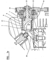
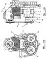
- FIG. 1 there is shown a single cylinder air cooled engine.
- the cylinder 2 has a piston 1 connected to a crankshaft 3 in the conventional manner for reciprocation in the cylinder 2.
- the upper part of the cylinder 2 is closed by a combustion chamber 4.
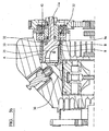
- the flow of inlet air/fuel mix and exhaust gas into and out of the combustion chamber 4 is controlled by a rotary valve 5, shown in cross-section in Figure 2 .
- the valve is rotatable in a valve housing in the combustion chamber housing about an axis .5a which is parallel to the axis of rotation 3a of the crankshaft 3.
- the rotary valve 5 has a driven pulley 17 mounted thereon which is connected to a drive pulley 18 on the engine crankshaft 3 by a belt drive arrangement, comprising an endless belt 19 having a toothed profile on its inner surface which drivingly engage with corresponding teeth on the pulleys 17 and 18.
- the pulleys, and hence the endless belt 19 also, lie in a common plane 20.
- the rotation of the crankshaft 3 and hence the piston movement is coordinated with the rotation of the rotary valve 5 so that the engine operates on the conventional four stroke cycle.
- the diameter of the driven pulley 17 is twice that of the drive pulley 18 so that the rotary valve 5 rotates at half engine speed.
- the rotary valve consists of a plain active valve having a first cylindrical part in the form of a shaft 6 mounted on a ball bearing arrangement 7 in the form of a single race ball bearing, located on a side of the valve 5 remote from the combustion chamber 4.
- the valve has a larger cylindrical body part 11 extending into the combustion chamber and having in its interior a volume 9 which forms part of the combustion chamber 4.
- the cylindrical part 11 is rotatable in a bore in a valve housing insert 8 in which the cylindrical part 11 of the valve 5 is a close sliding fit, with only a minimum clearance of a few microns provided between the rotary valve 5 and the bore of the valve housing insert 8.
- the insert 8 in the valve housing is formed of a bearing material such as phosphor bronze or similar copper-based alloy with a high tin content.
- the insert may be formed of an aluminium alloy with good heat dissipation properties with a hard coating such as anodised aluminium, a ceramic or silicon carbide coating such as Nikasil (a registered trademark).
- the hard coating material may be applied directly to the material of the cylinder body.
- the shaft 6 has an insert or sleeve 21 secured for rotation with the shaft 6 and contains on its outer periphery a flange 22 having an axially extending peripheral rib 23.
- a shoulder 25 is formed between the larger diameter part 11 of the rotary valve and the shaft 6 and this shoulder 25 abuts the inner race 24 of the bearing 7 in the assembled condition to prevent the valve from moving in the axial direction away from the cylinder when the combustion chamber pressure is positive.
- Resilient means in the form of an O-ring 43 or wave washer is located in the peripheral groove formed by the flange 22 and rib 23 and this serves to hold the valve axially when a negative pressure is formed in the combustion chamber during the induction stroke and serves to prevent the valve oscillating axially in this situation when the combustion chamber pressure acting on the valve varies from negative to positive and vice versa.
- the rotary valve 5 has in its interior a volume 9, as illustrated in Figure 2 and particularly Figures 4A and 4C , which forms part of the combustion chamber 4.
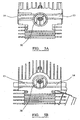
- the combustion chamber 4 consists of a closed part-hemispherical upper end in the volume 9 and an inclined wedge-shaped passage 30 forming an inclined passage which leads to the piston and the cylinder and which in cross-section is like a Norman arch as can be seen in Figures 5A and 5B .
- the wedge shaped passage 30 leads to the cylinder cavity. In the cylinder cavity there is a squish area 31 between the piston and the combustion chamber housing 32.
- the size and shape of the passage in the wedge shape part 30 is designed both to give the required compression ratio and also as a passage with good flow characteristics to allow for efficient gas transfer between the ports 13, 14 and the cylinder volume during the inlet and exhaust phases of the four stroke cycle. During the compression stroke the air fuel mixture is forced past the sparking plug towards the valve to ensure maximum combustion efficiency when ignition occurs.
- the top of the piston is shaped to protrude into the wedge shaped chamber to provide the required compression ratio.
- the wall part 11 of the rotary valve has a port 12 (see also Figures 4A and 4C ) giving fluid access to and from the combustion chamber 4 through inlet and exhaust ports 13, 14 in the valve housing 8, illustrated particularly in the schematic cross-sections of Figure 5A and 5B .
- the drawings also illustrate a spark plug 15.
- the rotary valve body is formed of a steel, such as EN40B, which has been plasma nitrided and then ground into its final size, before being provided with a PVD coating such as a DLC (Diamond like Carbon) coating or a PVD ceramic coating.
- the inlet and exhaust ports 13, 14 are located on opposite sides of the engine with their longitudinal axes parallel, as is advantageous in most circumstances.
- the inlet port 13 is located on the right-hand side and the exhaust port 14 is located on the left-hand side.
- the ports it is possible for the ports to be located on the lower part of the rotary valve, that is between the axis of the valve and the crankshaft, in which case given that the rotary valve is rotating in the direction shown the inlet port 13 is on the left-hand side and the exhaust port 14 on the right, as shown in Figure 5B .
- combustion gases also tend to leak through the path B between the valve body 11 and its housing 8 into the cavity containing the bearing 7.
- This embodiment of the invention seeks to reduce the leakage along path B by providing a ring of steel 8a, or other material with a low coefficient of expansion, embedded within the valve housing insert. This controls the thermal expansion of this region of the valve reducing the leakage path. This area of the valve is removed from the main area of combustion and runs at significantly lower temperatures, hence tighter clearances can be run without any risk of seizure.
- the leak path B is closed by a spring ring 32, in the manner of a piston ring which lies between the shoulder 25 on the valve body 11 and the inner race 24 of the bearing.
- the light pressure of the O ring holding the spring ring 32 lightly between the valve and the bearing allows the spring ring 32 to move outwards to engage with the inner diameter of the valve housing 8.
- the spring ring 32 is sprung outwards to form a seal between the outer radial surface of the ring 32 and the inner radial surface of the valve housing 8.
- combustion pressure Under maximum pressure in the combustion chamber, combustion pressure generates a compression force on the valve which is transmitted through the spring ring 32 to the bearing arrangement to urge the planar surfaces of the spring ring 32 into firmer contact with both the valve shoulder 25 and inner race 24 thereby reducing leakage at this point.
- FIG. 3B and 4A there is shown an alternative embodiment of a ring seal design to close leak path B.
- the spring ring 32 lies within a groove 11a in the valve body 11. Its planar surface furthest from the combustion chamber abuts the adjacent planar surface of the groove 11a. It is held in this position by a wave spring 32a or similar device fitted within the groove 11a between the planar surface of the ring nearest the combustion chamber and the adjacent planar surface of the groove 11 a. This provides the initial sealing contact between the planar surfaces.
- the ring 32 is also lightly sprung outwards to provide the initial sealing force between the outer radial surface of the ring 30 and the inner radial surface of the valve housing 8. Under maximum pressure in the combustion chamber combustion gases enter the space between the ring 32 and valve body behind the ring to urge both the planar and radial sealing surfaces into firmer contact thereby reducing leakage at this point.
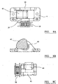
- the leak path A is sealed by an annular part-cylindrical sleeve 33 which is located on the exterior of the valve body 11, as shown in Figures 4A, 4B and 4C .
- the sleeve 33 has an opening 34 which coincides with the port 12 in the valve body and is located relative to the valve body by a peg 35 which prevents rotation of the ring and axial movement relative to the valve but enables the sleeve 33 to be able to float and expand radially.
- the part cylindrical sleeve 33 is biased resiliently outwards and operates in a similar manner to a conventional piston ring of a conventional internal combustion engine in which the combustion gases get behind the ring and urge it into contact with the cylinder wall.
- the gases get between the sleeve 33 and the valve body 11 so as to urge the ring outwardly in the direction to seal the path A.
- the sealing forces are correspondingly reduced, the spring action of the sleeve providing a low contact pressure between the rotating valve and the valve housing to form an initial seal.
- the sleeve has a slightly larger internal diameter than the diameter of the valve to provide an initial gap for the gases to enter more easily.
- the belt drive arrangement consists of a toothed drive pulley 17A on the crankshaft and a toothed driven pulley driving the rotary valve, the drive being transmitted through a flat toothed belt 19A.
- the drive arrangement includes a further balance shaft toothed pulley 38 driven by the toothed belt 19A.
- the toothed belt has teeth on both its inner and outer surfaces to transmit the drive.
- the balance shaft is driven by the teeth on the opposite side of the belt to those that are engaged with the crankshaft pulley.
- Figure 7 it can be seen that all three pulleys lie in the common radial plane 20.
- the balance shaft 40 is rotatably mounted in bearings 39 in a frame 41 adapted to be bolted to the main housing of the engine, the shaft having an offset balance weight 42 designed to give the desired balancing characteristics.
- the balance shaft drive pulley 38 is secured to the shaft 40 on the exterior of the frame 41 .
- the balance shafts 43 are each rotatably mounted in bearings 44 in lugs 45 extending from the crankcase 46, the shafts 43 each having an offset balance weight 47 designed to give the desired counter-balancing characteristics.
- the balance shafts 43 are arranged either side of the crankshaft 3, substantially equidistant from the centreline 48 of the cylinder 2.and driven by a double sided toothed belt 49 The centre of mass of each offset balance weight 47 is aligned with the centreline of the cylinder 2.
- This arrangement enables the combined centre of mass of the two offset balance weights 47 to be substantially aligned with the axis 48 of the cylinder, said arrangement ensuring that the net force generated by the balance shafts 47 is substantially in line with the axis 48 of the cylinder, and therefore in line with the reciprocating forces generated by the piston, thereby minimising vibration at the engine mounting points
- FIG. 10A and 10B there is shown a further embodiment of the engine with the twin contra rotating balance shafts which incorporates on each shaft a contra rotating flywheel 50 to also reduce torque recoil.
- the total rotational inertia of the two contra rotating flywheels 50 is substantially the same as that of the engine crank train and flywheel, thereby minimising torque recoil forces at the engine mounting points.
Landscapes
- Engineering & Computer Science (AREA)
- Mechanical Engineering (AREA)
- General Engineering & Computer Science (AREA)
- Combustion Methods Of Internal-Combustion Engines (AREA)
- Valve-Gear Or Valve Arrangements (AREA)
- Valve Device For Special Equipments (AREA)
- Cylinder Crankcases Of Internal Combustion Engines (AREA)
- Mechanically-Actuated Valves (AREA)
- Electrically Driven Valve-Operating Means (AREA)
Claims (3)
- Moteur à combustion interne à soupape rotative ayant un piston (1) connecté à un vilebrequin (3) et pouvant aller et venir dans un cylindre (2), une chambre de combustion (4) étant définie en partie par le piston (1), et une soupape rotative (5) pouvant tourner dans un logement de soupape (8) fixé par rapport au cylindre (2), la soupape rotative (5) ayant un corps de soupape contenant un volume (9) définissant en partie la chambre de combustion (4) et ayant en outre dans une partie de paroi (11) de celle-ci un orifice (12) donnant au cours de la rotation de la soupape une communication fluidique successivement vers et depuis la chambre de combustion (4) par le biais d'orifices d'entrée et d'échappement (13, 14) dans le logement de soupape, dans lequel la soupape rotative peut tourner autour d'un axe (5a) parallèle à l'axe de rotation (3a) du vilebrequin (3), dans lequel le volume (9) dans le corps de soupape rotative conduit à un passage (30), le passage (30) dirigeant l'écoulement de gaz de combustion entre le volume (9) dans la soupape et le cylindre (2), le passage (30) définissant également en partie la chambre de combustion (4), le passage (30) étant un volume essentiellement en forme de coin incliné par rapport à l'axe (5a) de la soupape vers le cylindre (2) à un angle compris entre 30 et 60 degrés depuis l'axe de rotation (5a) de la soupape, caractérisé en ce que la partie du corps de soupape contenant le volume (9) définissant une partie de la chambre de combustion (4) se situe au moins partiellement radialement vers l'intérieur de la circonférence du cylindre pour recouvrir le piston (1).
- Moteur à combustion interne à soupape rotative selon la revendication 1, dans lequel, lorsque le moteur est un moteur à allumage commandé, la bougie d'allumage (15) est située dans la surface supérieure du passage (30) adjacente à la région où le passage (30) rencontre le volume (9) dans la soupape rotative (5).
- Moteur à combustion interne à soupape rotative selon l'une quelconque des revendications précédentes, dans lequel le piston a une zone surélevée qui fait saillie dans le passage (30) au point mort haut, la zone surélevée augmentant le taux de compression du moteur.
Applications Claiming Priority (2)
| Application Number | Priority Date | Filing Date | Title |
|---|---|---|---|
| GB1117259.0A GB2495314A (en) | 2011-10-06 | 2011-10-06 | A rotary valve internal combustion engine |
| PCT/GB2012/052471 WO2013050776A2 (fr) | 2011-10-06 | 2012-10-05 | Moteur à combustion interne à soupape rotative |
Publications (2)
| Publication Number | Publication Date |
|---|---|
| EP2764218A2 EP2764218A2 (fr) | 2014-08-13 |
| EP2764218B1 true EP2764218B1 (fr) | 2017-04-19 |
Family
ID=45035256
Family Applications (1)
| Application Number | Title | Priority Date | Filing Date |
|---|---|---|---|
| EP12779146.5A Active EP2764218B1 (fr) | 2011-10-06 | 2012-10-05 | Moteur à combustion interne à soupape rotative |
Country Status (6)
| Country | Link |
|---|---|
| US (1) | US9644505B2 (fr) |
| EP (1) | EP2764218B1 (fr) |
| JP (1) | JP6214005B2 (fr) |
| CN (1) | CN103890329B (fr) |
| GB (1) | GB2495314A (fr) |
| WO (1) | WO2013050776A2 (fr) |
Families Citing this family (3)
| Publication number | Priority date | Publication date | Assignee | Title |
|---|---|---|---|---|
| DE102016120147A1 (de) * | 2015-11-05 | 2017-05-11 | Borgwarner Inc. | Schaltsystem mit bedarfsschmierung und mechanischem eco-ventil |
| DE102016111755B4 (de) * | 2016-06-27 | 2018-05-24 | Federal-Mogul Valvetrain Gmbh | Verfahren zur Beschichtung eines Ventilkopfes eines Ein- oder Auslass-Ventils sowie ein solches Ein- oder Auslassventil |
| US11377982B2 (en) * | 2018-09-06 | 2022-07-05 | Rcv Engines Limited | Rotary valve internal combustion engine |
Family Cites Families (33)
| Publication number | Priority date | Publication date | Assignee | Title |
|---|---|---|---|---|
| GB190928797A (en) * | 1909-10-02 | 1910-02-17 | Swift Motor Company Ltd | Improvements in or relating to Valves and Valve Gearing for Internal Combustion Engines. |
| FR418427A (fr) | 1910-06-29 | 1910-12-09 | Georges Sonck | Distribution rotative pour moteurs à explosion |
| US1156663A (en) * | 1912-05-08 | 1915-10-12 | Fred D Calkins | Internal-combustion engine. |
| US1186848A (en) * | 1915-09-14 | 1916-06-13 | George L Schofield | Balanced rotary valve. |
| GB118244A (en) * | 1918-03-28 | 1918-08-22 | Raymond Felicien Desir Dongrie | Improvements relating to Rotating Sleeve Valves for Internal Combustion Engines. |
| GB292572A (en) * | 1927-06-24 | 1928-08-23 | Motor Res Company | Improvements in or relating to rotary valves, particularly for internal-combustion engines and compressors |
| US2354305A (en) * | 1941-09-18 | 1944-07-25 | Cross Roland Claude | Rotary valve controlled internal-combustion engine |
| GB1473107A (fr) * | 1973-09-07 | 1977-05-11 | ||
| US3906922A (en) * | 1973-10-15 | 1975-09-23 | Jr Ernest Blaney Dane | Stratified charge engine |
| GB1505148A (en) * | 1975-08-12 | 1978-03-30 | Hepworth & Grandage Ltd | Pistons |
| US4494500A (en) * | 1982-06-01 | 1985-01-22 | Hansen Engine Corporation | Rotary valve assembly |
| US4773364A (en) * | 1984-11-15 | 1988-09-27 | Hansen Engine Corporation | Internal combustion engine with rotary combustion chamber |
| JPS61234211A (ja) * | 1985-02-07 | 1986-10-18 | ゲアハ−ダス コ−ネリアス クリ−ク | 燃焼室バルブ |
| JPS61229909A (ja) * | 1985-04-02 | 1986-10-14 | Setsuo Nakamura | 内燃機関の回転弁 |
| WO1986005842A1 (fr) * | 1985-04-05 | 1986-10-09 | Honda Giken Kogyo Kabushiki Kaisha | Mecanisme d'entrainement des soupapes pour moteurs a combustion interne |
| US4658776A (en) * | 1986-02-03 | 1987-04-21 | Coman Clyde R | Rotary valve internal combustion engine |
| US4867117A (en) * | 1987-12-22 | 1989-09-19 | Scalise Michael A | Rotary valve with integrated combustion chamber |
| JPH03104111U (fr) * | 1990-02-14 | 1991-10-29 | ||
| DE4040936A1 (de) * | 1990-12-20 | 1992-06-25 | Kloeckner Humboldt Deutz Ag | Hubkolbenbrennkraftmaschine |
| JPH05256114A (ja) * | 1992-03-11 | 1993-10-05 | Mitsubishi Heavy Ind Ltd | 回転弁式4サイクルガソリンエンジン |
| DE4217608A1 (de) | 1992-05-27 | 1993-04-08 | Karl Peter Stracke | Steuerelement fuer verbrennungsmotor |
| AU7335194A (en) * | 1993-07-15 | 1995-02-13 | Onan Corporation | Balanced engine driven generator set |
| GB2281350A (en) * | 1993-08-24 | 1995-03-01 | Robert Geoffrey Marshall | Four-stroke engine rotary valve gear |
| US5474036A (en) * | 1994-02-25 | 1995-12-12 | Hansen Engine Corporation | Internal combustion engine with rotary valve assembly having variable intake valve timing |
| US5771849A (en) | 1995-09-15 | 1998-06-30 | Hamy; Norbert | Internal combustion engine with crankcase pressure barrier |
| US5870980A (en) * | 1996-02-01 | 1999-02-16 | Hooper; Bernard | Stepped piston internal combustion engine |
| US6321699B1 (en) * | 1997-08-25 | 2001-11-27 | Richard Berkeley Britton | Spheroidal rotary valve for combustion engines |
| CN2466354Y (zh) * | 2001-03-07 | 2001-12-19 | 邓在积 | 旋转气门发动机 |
| US7814878B2 (en) * | 2007-05-07 | 2010-10-19 | Ford Global Technologies, Llc | System and method for operation of an engine having multiple combustion modes and adjustable balance shafts |
| GB2457947B (en) | 2008-02-29 | 2012-10-17 | Sumitomo Electric Industries | All solid photonic bandgap fibre |
| DE102008039255A1 (de) * | 2008-08-20 | 2010-02-25 | Blinov, Mikhail V. | Viertakt-Verbrennungsmotor |
| WO2010069336A1 (fr) * | 2008-12-15 | 2010-06-24 | Abdel Fattah Mohamed Hatem Abouseira | Moteur alternatif a quatre temps fonctionnant sans soupapes ni arbre a cames |
| GB2467947B (en) * | 2009-02-20 | 2013-10-09 | Rcv Engines Ltd | An internal combustion engine |
-
2011
- 2011-10-06 GB GB1117259.0A patent/GB2495314A/en not_active Withdrawn
-
2012
- 2012-10-05 CN CN201280049480.XA patent/CN103890329B/zh active Active
- 2012-10-05 US US14/348,234 patent/US9644505B2/en active Active
- 2012-10-05 JP JP2014533988A patent/JP6214005B2/ja active Active
- 2012-10-05 WO PCT/GB2012/052471 patent/WO2013050776A2/fr not_active Ceased
- 2012-10-05 EP EP12779146.5A patent/EP2764218B1/fr active Active
Also Published As
| Publication number | Publication date |
|---|---|
| US20140366818A1 (en) | 2014-12-18 |
| JP2014534371A (ja) | 2014-12-18 |
| GB201117259D0 (en) | 2011-11-16 |
| JP6214005B2 (ja) | 2017-10-18 |
| GB2495314A (en) | 2013-04-10 |
| CN103890329A (zh) | 2014-06-25 |
| WO2013050776A3 (fr) | 2013-05-30 |
| EP2764218A2 (fr) | 2014-08-13 |
| CN103890329B (zh) | 2016-08-31 |
| US9644505B2 (en) | 2017-05-09 |
| WO2013050776A2 (fr) | 2013-04-11 |
Similar Documents
| Publication | Publication Date | Title |
|---|---|---|
| US6205960B1 (en) | Rotary and reciprocating internal combustion engine and compressor | |
| US6308677B1 (en) | Overhead rotary valve for engines | |
| KR100710916B1 (ko) | 분리형 4행정 사이클 내연 엔진 | |
| US20080134998A1 (en) | Rotary internal combustion engine | |
| US11891930B2 (en) | Exhaust valve assembly for a two-stroke internal combustion engine | |
| KR960000437B1 (ko) | 왕복운동기계 | |
| EP2764218B1 (fr) | Moteur à combustion interne à soupape rotative | |
| KR20150131282A (ko) | 로터리 엔진, 가스 압축기 및 액체 펌프 | |
| WO2012168696A2 (fr) | Dispositif moteur rotatif | |
| JPH06323159A (ja) | レシプロエンジン | |
| US7357108B2 (en) | Valve-operating mechanism | |
| WO2014191781A1 (fr) | Moteur à combustion interne à piston rotatif | |
| EP2882943B1 (fr) | Moteur à combustion interne à soupape rotative | |
| WO2015088347A1 (fr) | Moteur à combustion comprenant un cylindre | |
| EP3847346B1 (fr) | Moteur à combustion interne à soupape rotative | |
| KR20090055707A (ko) | 세기 엔진 | |
| TWI825061B (zh) | 旋轉閥內燃機 | |
| JP2019070371A (ja) | 内燃機関 | |
| CN110185514A (zh) | 一种旋转气阀式发动机 | |
| KR20120100092A (ko) | 3 행정 로터리 엔진 | |
| JPH02301607A (ja) | 回転式スリーブバルブ内燃機関 | |
| JPH0925801A (ja) | スピン連続回転を往復動に併用したピストン・シリンダ機械 |
Legal Events
| Date | Code | Title | Description |
|---|---|---|---|
| PUAI | Public reference made under article 153(3) epc to a published international application that has entered the european phase |
Free format text: ORIGINAL CODE: 0009012 |
|
| 17P | Request for examination filed |
Effective date: 20140326 |
|
| AK | Designated contracting states |
Kind code of ref document: A2 Designated state(s): AL AT BE BG CH CY CZ DE DK EE ES FI FR GB GR HR HU IE IS IT LI LT LU LV MC MK MT NL NO PL PT RO RS SE SI SK SM TR |
|
| DAX | Request for extension of the european patent (deleted) | ||
| 17Q | First examination report despatched |
Effective date: 20160303 |
|
| GRAP | Despatch of communication of intention to grant a patent |
Free format text: ORIGINAL CODE: EPIDOSNIGR1 |
|
| GRAJ | Information related to disapproval of communication of intention to grant by the applicant or resumption of examination proceedings by the epo deleted |
Free format text: ORIGINAL CODE: EPIDOSDIGR1 |
|
| INTG | Intention to grant announced |
Effective date: 20161013 |
|
| GRAP | Despatch of communication of intention to grant a patent |
Free format text: ORIGINAL CODE: EPIDOSNIGR1 |
|
| INTG | Intention to grant announced |
Effective date: 20161108 |
|
| INTG | Intention to grant announced |
Effective date: 20161115 |
|
| GRAS | Grant fee paid |
Free format text: ORIGINAL CODE: EPIDOSNIGR3 |
|
| GRAA | (expected) grant |
Free format text: ORIGINAL CODE: 0009210 |
|
| AK | Designated contracting states |
Kind code of ref document: B1 Designated state(s): AL AT BE BG CH CY CZ DE DK EE ES FI FR GB GR HR HU IE IS IT LI LT LU LV MC MK MT NL NO PL PT RO RS SE SI SK SM TR |
|
| REG | Reference to a national code |
Ref country code: GB Ref legal event code: FG4D |
|
| REG | Reference to a national code |
Ref country code: CH Ref legal event code: EP |
|
| REG | Reference to a national code |
Ref country code: AT Ref legal event code: REF Ref document number: 886185 Country of ref document: AT Kind code of ref document: T Effective date: 20170515 |
|
| REG | Reference to a national code |
Ref country code: IE Ref legal event code: FG4D |
|
| REG | Reference to a national code |
Ref country code: DE Ref legal event code: R096 Ref document number: 602012031385 Country of ref document: DE |
|
| REG | Reference to a national code |
Ref country code: NL Ref legal event code: MP Effective date: 20170419 |
|
| REG | Reference to a national code |
Ref country code: LT Ref legal event code: MG4D |
|
| REG | Reference to a national code |
Ref country code: AT Ref legal event code: MK05 Ref document number: 886185 Country of ref document: AT Kind code of ref document: T Effective date: 20170419 |
|
| PG25 | Lapsed in a contracting state [announced via postgrant information from national office to epo] |
Ref country code: NL Free format text: LAPSE BECAUSE OF FAILURE TO SUBMIT A TRANSLATION OF THE DESCRIPTION OR TO PAY THE FEE WITHIN THE PRESCRIBED TIME-LIMIT Effective date: 20170419 |
|
| REG | Reference to a national code |
Ref country code: FR Ref legal event code: PLFP Year of fee payment: 6 |
|
| PG25 | Lapsed in a contracting state [announced via postgrant information from national office to epo] |
Ref country code: GR Free format text: LAPSE BECAUSE OF FAILURE TO SUBMIT A TRANSLATION OF THE DESCRIPTION OR TO PAY THE FEE WITHIN THE PRESCRIBED TIME-LIMIT Effective date: 20170720 Ref country code: NO Free format text: LAPSE BECAUSE OF FAILURE TO SUBMIT A TRANSLATION OF THE DESCRIPTION OR TO PAY THE FEE WITHIN THE PRESCRIBED TIME-LIMIT Effective date: 20170719 Ref country code: AT Free format text: LAPSE BECAUSE OF FAILURE TO SUBMIT A TRANSLATION OF THE DESCRIPTION OR TO PAY THE FEE WITHIN THE PRESCRIBED TIME-LIMIT Effective date: 20170419 Ref country code: FI Free format text: LAPSE BECAUSE OF FAILURE TO SUBMIT A TRANSLATION OF THE DESCRIPTION OR TO PAY THE FEE WITHIN THE PRESCRIBED TIME-LIMIT Effective date: 20170419 Ref country code: LT Free format text: LAPSE BECAUSE OF FAILURE TO SUBMIT A TRANSLATION OF THE DESCRIPTION OR TO PAY THE FEE WITHIN THE PRESCRIBED TIME-LIMIT Effective date: 20170419 Ref country code: HR Free format text: LAPSE BECAUSE OF FAILURE TO SUBMIT A TRANSLATION OF THE DESCRIPTION OR TO PAY THE FEE WITHIN THE PRESCRIBED TIME-LIMIT Effective date: 20170419 Ref country code: ES Free format text: LAPSE BECAUSE OF FAILURE TO SUBMIT A TRANSLATION OF THE DESCRIPTION OR TO PAY THE FEE WITHIN THE PRESCRIBED TIME-LIMIT Effective date: 20170419 |
|
| PG25 | Lapsed in a contracting state [announced via postgrant information from national office to epo] |
Ref country code: IS Free format text: LAPSE BECAUSE OF FAILURE TO SUBMIT A TRANSLATION OF THE DESCRIPTION OR TO PAY THE FEE WITHIN THE PRESCRIBED TIME-LIMIT Effective date: 20170819 Ref country code: PL Free format text: LAPSE BECAUSE OF FAILURE TO SUBMIT A TRANSLATION OF THE DESCRIPTION OR TO PAY THE FEE WITHIN THE PRESCRIBED TIME-LIMIT Effective date: 20170419 Ref country code: RS Free format text: LAPSE BECAUSE OF FAILURE TO SUBMIT A TRANSLATION OF THE DESCRIPTION OR TO PAY THE FEE WITHIN THE PRESCRIBED TIME-LIMIT Effective date: 20170419 Ref country code: BG Free format text: LAPSE BECAUSE OF FAILURE TO SUBMIT A TRANSLATION OF THE DESCRIPTION OR TO PAY THE FEE WITHIN THE PRESCRIBED TIME-LIMIT Effective date: 20170719 Ref country code: SE Free format text: LAPSE BECAUSE OF FAILURE TO SUBMIT A TRANSLATION OF THE DESCRIPTION OR TO PAY THE FEE WITHIN THE PRESCRIBED TIME-LIMIT Effective date: 20170419 Ref country code: LV Free format text: LAPSE BECAUSE OF FAILURE TO SUBMIT A TRANSLATION OF THE DESCRIPTION OR TO PAY THE FEE WITHIN THE PRESCRIBED TIME-LIMIT Effective date: 20170419 |
|
| REG | Reference to a national code |
Ref country code: DE Ref legal event code: R097 Ref document number: 602012031385 Country of ref document: DE |
|
| PG25 | Lapsed in a contracting state [announced via postgrant information from national office to epo] |
Ref country code: EE Free format text: LAPSE BECAUSE OF FAILURE TO SUBMIT A TRANSLATION OF THE DESCRIPTION OR TO PAY THE FEE WITHIN THE PRESCRIBED TIME-LIMIT Effective date: 20170419 Ref country code: DK Free format text: LAPSE BECAUSE OF FAILURE TO SUBMIT A TRANSLATION OF THE DESCRIPTION OR TO PAY THE FEE WITHIN THE PRESCRIBED TIME-LIMIT Effective date: 20170419 Ref country code: RO Free format text: LAPSE BECAUSE OF FAILURE TO SUBMIT A TRANSLATION OF THE DESCRIPTION OR TO PAY THE FEE WITHIN THE PRESCRIBED TIME-LIMIT Effective date: 20170419 Ref country code: SK Free format text: LAPSE BECAUSE OF FAILURE TO SUBMIT A TRANSLATION OF THE DESCRIPTION OR TO PAY THE FEE WITHIN THE PRESCRIBED TIME-LIMIT Effective date: 20170419 Ref country code: CZ Free format text: LAPSE BECAUSE OF FAILURE TO SUBMIT A TRANSLATION OF THE DESCRIPTION OR TO PAY THE FEE WITHIN THE PRESCRIBED TIME-LIMIT Effective date: 20170419 |
|
| PLBE | No opposition filed within time limit |
Free format text: ORIGINAL CODE: 0009261 |
|
| STAA | Information on the status of an ep patent application or granted ep patent |
Free format text: STATUS: NO OPPOSITION FILED WITHIN TIME LIMIT |
|
| PG25 | Lapsed in a contracting state [announced via postgrant information from national office to epo] |
Ref country code: IT Free format text: LAPSE BECAUSE OF FAILURE TO SUBMIT A TRANSLATION OF THE DESCRIPTION OR TO PAY THE FEE WITHIN THE PRESCRIBED TIME-LIMIT Effective date: 20170419 Ref country code: SM Free format text: LAPSE BECAUSE OF FAILURE TO SUBMIT A TRANSLATION OF THE DESCRIPTION OR TO PAY THE FEE WITHIN THE PRESCRIBED TIME-LIMIT Effective date: 20170419 |
|
| 26N | No opposition filed |
Effective date: 20180122 |
|
| PG25 | Lapsed in a contracting state [announced via postgrant information from national office to epo] |
Ref country code: SI Free format text: LAPSE BECAUSE OF FAILURE TO SUBMIT A TRANSLATION OF THE DESCRIPTION OR TO PAY THE FEE WITHIN THE PRESCRIBED TIME-LIMIT Effective date: 20170419 Ref country code: MC Free format text: LAPSE BECAUSE OF FAILURE TO SUBMIT A TRANSLATION OF THE DESCRIPTION OR TO PAY THE FEE WITHIN THE PRESCRIBED TIME-LIMIT Effective date: 20170419 |
|
| REG | Reference to a national code |
Ref country code: CH Ref legal event code: PL |
|
| REG | Reference to a national code |
Ref country code: IE Ref legal event code: MM4A |
|
| PG25 | Lapsed in a contracting state [announced via postgrant information from national office to epo] |
Ref country code: CH Free format text: LAPSE BECAUSE OF NON-PAYMENT OF DUE FEES Effective date: 20171031 Ref country code: LI Free format text: LAPSE BECAUSE OF NON-PAYMENT OF DUE FEES Effective date: 20171031 Ref country code: LU Free format text: LAPSE BECAUSE OF NON-PAYMENT OF DUE FEES Effective date: 20171005 |
|
| REG | Reference to a national code |
Ref country code: BE Ref legal event code: MM Effective date: 20171031 |
|
| PG25 | Lapsed in a contracting state [announced via postgrant information from national office to epo] |
Ref country code: BE Free format text: LAPSE BECAUSE OF NON-PAYMENT OF DUE FEES Effective date: 20171031 |
|
| PG25 | Lapsed in a contracting state [announced via postgrant information from national office to epo] |
Ref country code: MT Free format text: LAPSE BECAUSE OF NON-PAYMENT OF DUE FEES Effective date: 20171005 |
|
| REG | Reference to a national code |
Ref country code: FR Ref legal event code: PLFP Year of fee payment: 7 |
|
| PG25 | Lapsed in a contracting state [announced via postgrant information from national office to epo] |
Ref country code: IE Free format text: LAPSE BECAUSE OF NON-PAYMENT OF DUE FEES Effective date: 20171005 |
|
| PG25 | Lapsed in a contracting state [announced via postgrant information from national office to epo] |
Ref country code: HU Free format text: LAPSE BECAUSE OF FAILURE TO SUBMIT A TRANSLATION OF THE DESCRIPTION OR TO PAY THE FEE WITHIN THE PRESCRIBED TIME-LIMIT; INVALID AB INITIO Effective date: 20121005 |
|
| PG25 | Lapsed in a contracting state [announced via postgrant information from national office to epo] |
Ref country code: CY Free format text: LAPSE BECAUSE OF NON-PAYMENT OF DUE FEES Effective date: 20170419 |
|
| PG25 | Lapsed in a contracting state [announced via postgrant information from national office to epo] |
Ref country code: MK Free format text: LAPSE BECAUSE OF FAILURE TO SUBMIT A TRANSLATION OF THE DESCRIPTION OR TO PAY THE FEE WITHIN THE PRESCRIBED TIME-LIMIT Effective date: 20170419 |
|
| PG25 | Lapsed in a contracting state [announced via postgrant information from national office to epo] |
Ref country code: TR Free format text: LAPSE BECAUSE OF FAILURE TO SUBMIT A TRANSLATION OF THE DESCRIPTION OR TO PAY THE FEE WITHIN THE PRESCRIBED TIME-LIMIT Effective date: 20170419 |
|
| PG25 | Lapsed in a contracting state [announced via postgrant information from national office to epo] |
Ref country code: PT Free format text: LAPSE BECAUSE OF FAILURE TO SUBMIT A TRANSLATION OF THE DESCRIPTION OR TO PAY THE FEE WITHIN THE PRESCRIBED TIME-LIMIT Effective date: 20170419 |
|
| PG25 | Lapsed in a contracting state [announced via postgrant information from national office to epo] |
Ref country code: AL Free format text: LAPSE BECAUSE OF FAILURE TO SUBMIT A TRANSLATION OF THE DESCRIPTION OR TO PAY THE FEE WITHIN THE PRESCRIBED TIME-LIMIT Effective date: 20170419 |
|
| P01 | Opt-out of the competence of the unified patent court (upc) registered |
Effective date: 20230616 |
|
| PGFP | Annual fee paid to national office [announced via postgrant information from national office to epo] |
Ref country code: GB Payment date: 20250917 Year of fee payment: 14 |
|
| PGFP | Annual fee paid to national office [announced via postgrant information from national office to epo] |
Ref country code: FR Payment date: 20250925 Year of fee payment: 14 |
|
| PGFP | Annual fee paid to national office [announced via postgrant information from national office to epo] |
Ref country code: DE Payment date: 20251009 Year of fee payment: 14 |