EP2764294B1 - Brûleur sans flamme - Google Patents
Brûleur sans flamme Download PDFInfo
- Publication number
- EP2764294B1 EP2764294B1 EP12836643.2A EP12836643A EP2764294B1 EP 2764294 B1 EP2764294 B1 EP 2764294B1 EP 12836643 A EP12836643 A EP 12836643A EP 2764294 B1 EP2764294 B1 EP 2764294B1
- Authority
- EP
- European Patent Office
- Prior art keywords
- air
- fuel
- combustion
- burner
- flow
- Prior art date
- Legal status (The legal status is an assumption and is not a legal conclusion. Google has not performed a legal analysis and makes no representation as to the accuracy of the status listed.)
- Active
Links
Images





Classifications
-
- F—MECHANICAL ENGINEERING; LIGHTING; HEATING; WEAPONS; BLASTING
- F23—COMBUSTION APPARATUS; COMBUSTION PROCESSES
- F23D—BURNERS
- F23D14/00—Burners for combustion of a gas, e.g. of a gas stored under pressure as a liquid
- F23D14/02—Premix gas burners, i.e. in which gaseous fuel is mixed with combustion air upstream of the combustion zone
-
- F—MECHANICAL ENGINEERING; LIGHTING; HEATING; WEAPONS; BLASTING
- F23—COMBUSTION APPARATUS; COMBUSTION PROCESSES
- F23D—BURNERS
- F23D14/00—Burners for combustion of a gas, e.g. of a gas stored under pressure as a liquid
- F23D14/12—Radiant burners
- F23D14/126—Radiant burners cooperating with refractory wall surfaces
-
- F—MECHANICAL ENGINEERING; LIGHTING; HEATING; WEAPONS; BLASTING
- F23—COMBUSTION APPARATUS; COMBUSTION PROCESSES
- F23D—BURNERS
- F23D14/00—Burners for combustion of a gas, e.g. of a gas stored under pressure as a liquid
- F23D14/12—Radiant burners
- F23D14/151—Radiant burners with radiation intensifying means other than screens or perforated plates
-
- F—MECHANICAL ENGINEERING; LIGHTING; HEATING; WEAPONS; BLASTING
- F23—COMBUSTION APPARATUS; COMBUSTION PROCESSES
- F23D—BURNERS
- F23D14/00—Burners for combustion of a gas, e.g. of a gas stored under pressure as a liquid
- F23D14/12—Radiant burners
- F23D14/16—Radiant burners using permeable blocks
Definitions
- the present invention relates to No-NOx Burners and their applications. It relates particularly to Aphlogistic (flameless) No-NOx Burners and their applications.
- Fossil fuels are burned throughout the industrialized world to generate heat for heating homes and commercial buildings, for power generation, for use in industrial processes, and for many other applications.
- a special type of burner can be used. Such a burner is referred to generally as a low NOx burner. These special burners are effective in reducing the NOx produced from burning fossil fuels, but they still emit significant amounts of NOx. Furthermore, they are very complex and expensive.
- No-NOx burner which produces essentially zero (relative to ambient NOx) NOx during the combustion of natural gas or other fuel.
- Such No-NOx burners can be used in domestic, commercial, and industrial applications.
- FGR Flue Gas Recirculation
- DE 199 60 093 A1 describes a flameless burner in which a first combustion component and a second combustion component are supplied to a reaction zone which is a solid-free space formed between the outflow surface of a distributing pipe with narrow-dimensioned through-openings of a flashback preventer and the inflow surface of a porous body.
- the first combustion component which is non-ignitable or ignitable only with difficulty is supplied to the reaction zone via the flashback preventer and the second combustion component, which is a combustible gas/air mixture, is injected directly into the reaction zone.
- This application discloses a No-NOx burner which is capable of achieving low and even zero NOx from the flameless combustion of fossil fuel such as natural gas, propane, butane, etc.
- a flameless burner capable of zero-NOx and zero-CO comprises an Air-Fuel Ratio Attainment Means (AFRAM) and an Air-Fuel Mixing Means (AFMM) in fluid communication with the AFRAM to thoroughly mix the air and fuel to provide a readily combustible mixture, and one or more Radiant Combustion Zone (RCZ), and a Combustion Initiation Means (CIM) located in a combustion-initiation-contact position to initiate the combustion in the RCZ.
- the AFRAM is connected to a source of fuel and to a source of air, the AFRAM having means to achieve the required proportions of fuel and air there-through.
- the RCZ comprises one or more flow passages having a fluid flow inlet in fluid communication with the supply plenum of the AFMM and a hot gas discharge opening. During operation, the RCZ provides the intense radiant energy required to initiate and complete the combustion process and to promote and enhance flame-less combustion in the RCZ.
- the fluid communication between the supply plenum of the AFMM and the RCZ is provided by one or more high velocity fluid flow passages.
- Each passage has a cross-sectional flow area which is sufficient to create a gas velocity greater that the flame velocity to prevent pre-ignition in the supply plenum of the AFMM.
- the flameless burner further comprises a flow permeable structure (FPS) located in the fluid flow inlet of the RCZ to prevent pre-ignition in the supply plenum of the AFMM.
- the FPS may have through flow passages or may be a ceramic honeycomb with through flow passages or may be a porous ceramic structure with random through flow passages, or may be a wire mesh structure.
- the flameless burner further comprises an IR radiation reflector in the RCZ.
- the IR radiation reflector is located proximate to or at the flow discharge opening of the RCZ to intensify the IR radiation in the RCZ.
- the IR radiation reflector may be a porous FPS or a peripheral flow baffle.
- the RCZ is configured as a flat, hollow disc which comprises a flat bottom which contains the fluid flow inlet for fluid communication with the supply plenum of the AFMM, a flat top, and a cylindrical wall.
- the hot gas discharge opening is a plurality of orifices on the cylindrical wall of the hollow disc.
- the AFRAM may comprise an air eductor.
- flame As used herein the word “flame” may also mean combustion with no radiation that is visible to the human eye.
- Aphlogistic Burner A fuel-burner in which the combustion of the fuel occurs without the presence of a visible flame.
- Burner supply plenum is the chamber which feeds air and fuel to the premix type burner element.
- a well designed burner supply plenum provides well mixed air and fuel and also provides very even flow and very even pressure distribution to the burner.
- a flameless combustion cell is one of a plurality of small passages or cavities for promoting and enhancing flameless combustion in the burner.
- Flame back is the movement of the hot products of combustion from the combustion chamber into the supply plenum. This is undesirable as it will cause combustion in the supply plenum.
- Glow back is the process of heating the combustion guard from the hot end towards the cold end so that the fuel-air mixture in the burner supply plenum attains the auto ignition temperature. Glow back must be controlled so that the glow does not reach the burner supply plenum. If glow back occurs, the fuel and air will be ignited and will combust within the supply plenum; this situation is undesirable.
- the RCZ is a partially enclosed space which glows with intense infra-red radiation wherein flameless combustion takes place.
- the IRRR is an element of a structure which reflects the infrared (IR) radiation in the RCZ so that the IR radiation is generally contained within the RCZ.
- Combustion Trap Any structure which contains one or more IR radiation reflecting surfaces while allowing combustion products to pass through.
- Combustion Guard Any structure that prevents glow back or flameback.
- Porous structure is a fluid permeable solid, which can be utilized as the combustion guard or the combustion trap.
- the porous structure can be a matrix with randomly oriented flow-passages or an extrusion with regularly oriented flow passages or a wire mesh.
- PFB Peripheral Flow Baffle
- the AFRAM is a device wherein the proportions of the fuel and the combustion air can be set so as to provide a combustible mixture.
- the AFRAM can have control means such as valves for active control of the proportion of the fuel and air.
- the AFRAM could have fuel and air inlet ports which are pre-designed to allow the desired quantities of fuel and air into the AFRAM.
- the AFMM is a device wherein the fuel and air from the AFRAM are well mixed to sustain combustion in the RCZ.
- the AFMM could be a simple plenum or could be more elaborately designed with mixing vanes and other elements, both static or moving, to facilitate thorough mixing of the fuel and air.
- Combustion Initiation Means is any device such as a spark igniter, pilot flame, glow igniter or other device suitably positioned to initiate the combustion process in the RCZ.
- a burner which is capable of producing zero NOx and zero CO by passing a thoroughly mixed stream of air and fuel at an appropriate air/fuel ratio to maintain a temperature below the NOx forming threshold through a radiant combustion zone.
- the radiant combustion zone provides the intense radiant energy required to initiate and complete the combustion process.
- the temperature in the RCZ is controlled by the Air Fuel ratio which can be adjusted to attain low NOx and further zero NOx.
- the combustion temperature can be directly controlled with a suitable Air Fuel ratio. Increasing the excess air reduces the combustion temperature. This reduction in combustion temperature reduces the thermal NOx that is formed by the reaction of nitrogen with oxygen that normally takes place at the higher combustion temperatures of a conventional burner.
- the oxidation reaction does not produce carbon-monoxide and there is complete oxidation of the hydrocarbons to carbon-dioxide and water.
- the air and fuel provide the heat energy to keep the radiant combustion zone hot.
- the combustion according to this method is flameless and is capable of low NOx or no-NOx operation.
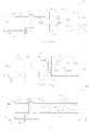
- Fig. 1A is a representation of the aphlogistic No-NOx burner 100 described herein in operation.
- burner 100 comprises an Air-Fuel Ratio Attainment Means (AFRAM) 110, an Air-Fuel Mixing Means (AFMM) 120, a RCZ 130, and a CIM 140.
- AFRAM Air-Fuel Ratio Attainment Means
- AFMM Air-Fuel Mixing Means
- RCZ 130 Air-Fuel Mixing Means
- CIM 140 CIM
- AFRAM 110 is configured as a Y-branched flow passage which has a larger flow passage 112 for the flow of the combustion air into AFRAM 110 and a smaller flow passage 114 for the flow of the fuel into AFRAM 110.
- Control means 112c is provided in flow passage 112 for the control of the quantity of combustion air that can enter AFRAM 110.
- Control means 112c could be a valve such as a butterfly valve, or a slide-gate valve, or any other manually or automatically activated fluid flow control device.
- a similar control means 114c is provided in flow passage 114 for the control of the quantity of fuel that can enter AFRAM 110. It is not necessary that active flow control elements be used as control means 112c and 114c.
- AFRAM 110 is a means to attain the required quantities of fuel and air into burner 100.
- a volumetric Air to Fuel ratio (with natural gas as the fuel) in the range of 10 to 22 is sufficient to enable sustained combustion of the Fuel Air Mixture (FAM).
- FAM Fuel Air Mixture
- the exact air-fuel ratio chosen for a particular application will be determined to attain the desired level of NOx or zero NOx and to meet other operating requirements as is well known in the art. For example, boiler operators may choose to operate with lower excess air to produce a low level of NOx within regulations while maximiizing heating efficiency.
- fuel is drawn through inlet 114i in flow passage 114 and through control means 114c.
- the fuel mixes with air which is drawn through inlet 112i in flow passage 112 and through control means 112c.
- the fuel air mixture flows into outlet flow passage 116 from where it exits into AFMM 120 wherein it is mixed thoroughly.
- AFMM 120 is configured as a flow passage with optional mixing vanes 120m.
- mixing means such as a longer plenum or vanes or baffles (not shown) or multiple fuel ports may be provided within AFFM 120 to enhance the mixing of the fuel and air within AFMM 120.
- the fuel-air mixture exits AFMM 120 into the combustion guard.
- the combustion guard is configured as a tapered outlet 116t on flow passage 116.
- the fuel-air mixture in tapered outlet 116t accelerates as it flows towards outlet 116e from which it emerges as a high velocity jet into RCZ 130.
- the high velocity of the fuel-air mixture as it exits outlet 116e acts as a combustion guard for preventing flame back of the flames into the AFMM 120.
- RCZ 130 is configured as a flow passage 130f with an inlet 130i which may be larger than the outlet 116e of AFMM 120 and an open outlet 130e.
- Flow passage 130f is lined internally with insulation 130n.
- the surface 130s of insulation 130i becomes hot and produces and reflects IR radiation to enable RCZ 130 to perform and function as a radiant combustion chamber.
- the aspect ratio (length divided by hydraulic diameter) of flow passage 130f be between 1 to 10.
- CIM 140 is located in a combustion-initiation-contact position to initiate the combustion of the fuel-air mixture as it exits AFMM 120.
- CIM 140 is activated to initiate the combustion of the fuel-air mixture as it exits though flow outlet 116e of tapered flow passage 116t. Initially, flames are produced after the outlet 116e of tapered flow passage 116t. However, after insulation 130n heats up, its internal surfaces 130s begin to produce IR radiation and also reflect the IR radiation produced by combustion and flameless combustion will occur within RCZ 130.
- the burner provides flameless combustion without any NOx and Carbon-monoxide being produced by the combustion process. It will obvious that burner 100 could be operated with less excess air to produce ultra-low NOX.
- Fig. 1B is another embodiment of aphlogistic burner 100 wherein the first end of flow passage 130f has a closure 130c which has an inlet opening 130i which matches the outlet opening 116e of tapered flow passage 116t.
- Closure 130c is internally insulated with insulation 130n whose internal surface 130s acts as an IR radiation producer and reflector to promote flameless combustion within RCZ 130.
- CIM 140 is located in a combustion-initiation-contact position at outlet 130e of RCZ 130 to initiate the combustion of the fuel-air mixture as it exits RCZ 130.
- CIM 140 is activated to initiate the combustion of the fuel-air mixture as it exits though flow outlet 130e of RCZ 130.
- flames are produced at the outlet 130e of RCZ 130.
- the high velocity of the fuel-air mixture out of outlet 116e acts as a combustion guard for preventing flame back of the combustion into the AFMM 120.
- the burner provides flameless combustion with low or no NOx and Carbon-monoxide being produced by the combustion process.
- Fig. 2A represents another embodiment of aphlogistic burner 100 wherein the aphlogistic burner 100 of Fig. 1A has a flow permeable porous structure 132 located in its outlet 130e.
- Porous structure 132 could be a ceramic or metallic foam with random flow passages, or a metal wire mesh or a ceramic extrusion with regular flow passages.
- Porous structure 132 acts an additional IRRR to further produce IR radiation and contain and reflect the IR radiation within RCZ 130.
- Porous structure 132 enhances the radiation within RCZ 130, thus enabling burner 100 of Fig. 2A to achieve a lower firing capacity.
- Fig. 2B represents another embodiment of aphlogistic burner 100 wherein the aphlogistic burner 100 of Fig. 1B has a flow permeable porous structure 132 located in its outlet 130e.
- Porous structure 132 could be a ceramic or metallic foam with random flow passages, or a metal wire mesh or a ceramic extrusion with regular flow passages.
- Porous structure 132 acts an additional IRRR to further contain the IR radiation within RCZ 130.
- porous structure 132 enhances the radiation within RCZ 130, thus enabling burner 100 of Fig. 2B to achieve a low or no NOx at a lower firing capacity.
- aphlogistic burner 100 uses a high velocity fuel-air mixture to prevent flameback into AFMM 120, other means of preventing flameback can be practiced.
- Fig. 3A represents another embodiment of aphlogistic burner 100 wherein fuel-air mixture flow passage 116 is not tapered to create a high velocity fuel-air mixture stream.
- Flow passage 116 opens directly into RCZ 130 without a tapered outlet as in aphlogistic burner 100 of Fig. 1A . Therefore the velocity of the fuel-air mixture in passage 116 could be lower than the flame velocity.
- a porous structure 122 is inserted into outlet 116e of flow passage 116 to function as a combustion guard. Outlet 116e may be smaller than inlet opening 130i to provide an air gap for secondary air.
- CIM 140 initiates the combustion of the fuel-air mixture as it exits porous structure 122.
- the flames are contained within RCZ 130 and heat insulation 130n. When surfaces 130i of insulation 130n get hot they start producing and reflecting the IR radiation and flameless combustion begins to take place in RCZ 130.
- Fig. 3B represents another embodiment of aphlogistic burner 100 wherein fuel-air mixture flow passage 116 is not tapered to create a high velocity fuel-air mixture stream.
- Flow passage 116 opens directly into RCZ 130 without a tapered outlet as in aphlogistic burner 100 of Fig. 1A .
- a porous structure 122 is inserted into outlet 116e of flow passage 116 to function as a combustion guard.
- the operation of aphlogistic burner 100 of Fig. 3B is similar to that of aphlogistic burner 100 of Fig, 3A .
- Fig. 4A represents yet another embodiment of aphlogistic burner 100 wherein a first porous structure 122 is provided in outlet 116e of fuel-air mixture flow passage 116 to function as a combustion guard as described previously with respect to aphlogistic burner 100 of Fig. 3B .
- Outlet 116e opens directly into RCZ 300 without an air gap for secondary air.
- a second porous structure 132 is inserted into outlet opening 130e of flow passage 130f of RCZ 130 as described previously with respect to aphlogistic burner 100 of Fig. 2A .
- the operation of aphlogistic burner 100 of Fig. 4A is similar to that of aphlogistic burner 100 of Fig. 3B .
- Fig. 4B represents yet another embodiment of aphlogistic burner 100 wherein a first porous structure 122 is provided in outlet 116e of FAM flow passage 116 to function as a combustion guard as described previously with respect to aphlogistic burner 100 of Fig. 3A .
- Outlet 116e may be smaller than inlet opening 130i to provide an air gap for secondary air.
- a second porous structure 132 is inserted into outlet opening 130e of flow passage 130f of RCZ 130 as described previously with respect to aphlogistic burner 100 of Fig. 2A .
- the operation of aphlogistic burner 100 of Fig. 4B is similar to that of aphlogistic burner 100 of Fig. 3A .
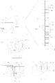
- Fig. 5 represents an aphlogistic burner 100 wherein the flow passage 130f of RCZ 130 is tapered outwards to allow for stable burner operation with a greater range of fuel-air mixture flowrates. This prevents the combustion gases from being blown out of passage 130f when the fuel-air mixture flowrate is increased to provide greater heater output.
- the active area wherein combustion takes place shifts axially within the tapered flow-passage depending on the flowrate of the fuel-air mixture.
- the operation of aphlogistic burner 100 of Fig. 5 is similar to that of aphlogistic burner 100 of Fig. 1B . It will be obvious that a tapered flow passages could be provided in any of the previously described aphlogistic burners of Figs. 1A to 4B .
- Fig. 6 represents another AB100 wherein a peripheral flow baffle 135 is provided at the outlet of RCZ 130.
- PFB 135 reflects the IR radiation back into RCZ 130.
- the products of combustion flow out of RCZ 130 in a radial direction in the gap between outlet 130e of RCZ 130 and PFB 135. This arrangement may be useful for example when it is necessary to shield other parts of the user's appliance from radiative heat effects.
- the operation of aphlogistic burner 100 of Fig. 6 is similar to that of aphlogistic burner 100 of Fig. 1B . It will be obvious that a PFB could be provided in any of the previously described aphlogistic burners of Figs. 1A to 4B .
- Fig. 7 represents an aphlogistic burner 100 wherein a plurality of RCZs 130 is provided in parallel to increase the IR radiation producing and reflecting surface area. This results in a potentially shorter RCZ and is useful in applications where space is limited or could allow the burner to operate at a lower capacity while still producing low or no-NOx
- the operation of aphlogistic burner 100 of Fig. 7 is similar to that of aphlogistic burner 100 of Fig, 1A .
- other means of increasing the IR radiation surface area could be practiced such as using honeycomb structure parallel to the flow, or parallel plates or reticulated ceramic foam or open coil of refractory material and others such means could be used in aphlogistic burner 100 of Fig. 7 .
- additional surface area as discussed above could be provided in any of the previously described aphlogistic burners of Figs. 1A to 4B .
- Fig. 8A represents an aphlogistic burner 100 wherein porous structure 122 is located at the inlets 130i of a very large plurality of RCZs 130 (Similar to the aphlogistic burner of Fig. 7 ) having very small cross-sectional areas and very short axial lengths.
- structured ceramic packing with very small cells such as those available commercially from suppliers such as Lantec Inc. of Agoura Hills, California - www.lantecp.com ) could be cut to very short lengths to create tiles with axial flow passages that could function as miniature RCZs in the aphlogistic burner 100 of Fig. 8A .
- aphlogistic burner 100 of Fig 8A can be tiled to provide a large surface area which acts as a radiant surface when burner 100 of Fig. 8A is in operation.
- porous structure 122 functions as a combustion guard.
- the operation of aphlogistic burner 100 of Fig 8A is similar to that described above for the aphlogistic burners of Fig. 3B and Fig. 7 .
- Aphlogistic burner 100 of Fig. 8A can be used for space heating or comfort heating or any other application wherein radiant heating is required.
- FIG. 8B to 8D show various other embodiments of porous structures that could be used as RCZ 130 in aphlogistic burner 100 of Fig. 8A .
- porous structure 122 is cast as a unitary porous structure with a homogenous porosity throughout its volume.
- RCZs 130 are configured as cavities on the fluid outlet face of porous structure 122.
- the upper cavitied section of porous structure 122 functions as miniature RCZs and the lower non-cavitied section of porous structure 122 functions as a combustion guard.
- feed passages 122f are provided within porous structure 122 to feed the fuel-air mixture into the cavities in porous body 122. This provides more uniform feed to the cavities with a lower pressure drop.
- the porosity of the combustion guard section of porous structure 122 is less than the porosity of the cavitied section of porous structure 122 to reduce pressure drop and provide a uniform flow of the fuel-air mixture into RCZs 130.
- Modifications such as a tapered combustion zone, etc. as described previously can also be incorporated in this embodiment.
- porous structure 122 Yet other structures are possible for use as porous structure 122. Such structures and modifications to above described structures will be obvious to persons having ordinary skills in the art.
- the internal surfaces of the cavities act as IR radiation reflectors reflecting IR radiation from the surfaces back into the fuel-air mixture.
- cavities in porous structure 122 essentially function as flameless combustion cells.
- flameless combustion cells are essentially cavities on the radiation producing face of burner 100.
- the cavities are designed to be large enough to cause the flame to retract back to the combustion section of porous structure 122.
- the containment of the flame within the cavities assures rapid heating of the miniature RCZs to attain the auto-ignition temperature of the gaseous fuel-air mixture which, as described above, permeates or flows into the cavities from AFMM 120 through the combustion guard. If the cavities are too small to prevent flameback from occurring, the heating of the miniature RCZs will depend on glow back only.
- the heating of the miniature RCZs will be much slower or may be inadequate to cause auto-ignition of the fuel to occur within the cavities when using natural gas as a fuel.
- the applicant has experimentally determined that a cavities cross-sectional dimension of about 4-mm (0.15 inch) is very adequate to promote rapid flame-back within the cavities to cause auto-ignition of the fuel to occur within the cavities.
- the wall thickness "t" (shown in Figs. 8A to 8D ) between adjacent cavities only needs to be enough to provide a rugged burner element. Excess wall material will only restrict air and gas flow on a burner diameter basis. The additional wall material also will increase the time required to heat the cavities to auto-ignition temperature. A flameless combustion cell wall thickness "t" of about 1 mm or less will provide good strength if a good ceramic material is chosen and will heat up in several seconds.
- porous structure 122 should provide good strength at all temperatures, good tolerance to thermal shock, and have a high emissivity.
- the material of construction of porous structure 122 also should be unaffected chemically by the products of combustion of the fuel.
- burner 100 of Figs. 1A to 8B would function also to burn-off completely the fine carbon particles, re-condensed hydrocarbon particles or soot that is generally produced during the combustion of a fuel.
- the above described embodiments of burner 100 would be a cleaner burner which creates very little and possibly no particulate pollution.
- flow passage 130f which functions as the RCZ 130
- flow passage 130 could have any suitable configuration, which could include bends and turns and other flow re-directions.
- Fig. 9A is an isometric exploded-view representation of an embodiment of an aphlogistic No-NOx burner 400 that has an attached extended radially configured radiant combustion chamber.
- Fig. 9B is a longitudinal elevation representation of the burner of Fig. 9A . This burner is similar to the burner of Fig. 1B except that the combustion chamber is ring-shaped rather than cylindrical shaped.
- the combustion chamber comprises an upper disc 410s and a lower washer-shaped disc 420s.
- the outer diameter of disc 420s matches the outer diameter of disc 410s.
- Ceramic insulation 410r and 420r is provided on the opposing faces of discs 410s and 420s.
- a venturi-shaped air inlet 440 is attached to the opening 420h of disc 420s at its non-opposing face.
- a gaseous fuel nozzle 430 is located within air inlet 440. When the gaseous fuel is directed into air inlet 440, venturi action induces ambient air into air inlet 440.
- the air-fuel mixture enters the radiant combustion zone (RCZ) between discs 410s and 420s wherein the fuel is combusted.
- the hot flue gases flow out radially along the circumference of discs 420s and 410s. Because combustion takes place in the radiant zone, there will be no production of NOx in this burner if operated correctly.
- ribs, bumps and other perturbations can be molded into the ceramic insulation 410r and 420r. Yet other means of adding surface area within the RCZ could be considered also.
- the perturbations can be designed to provide a swirling movement to the flue gases as they exit the circumferential outlet of the burner. This arrangement may be particularly useful for domestic hot water heaters wherein the swirl will ensure even heating and heat transfer in the lower section below the hot water tank. The swirl will also accelerate as it enters the central pipe within the hot water heater tank. The high angular velocity will enhance heat transfer in this central pipe.
- Fig. 9C shows a variation of the burner of Fig. 9B wherein the hot products of combustion are vented through a centered exhaust 410se. This arrangement provides focussed heating which is useful in many applications such as cooking stoves, boilers, scrap metal melting pots, etc.
- Fig. 9D shows another variation of the burner of Fig. 9B wherein the hot products of combustion are vented through multiple orifices 410sr.
- Fig. 10 represents another embodiment of aphlogistic burner 100 wherein RCZ 130 has two right angle bends which further facilitates the containment of the IR radiation within RCZ 130 to promote flameless combustion with zero-NOx and zero-CO.
- the operation of aphlogistic burner 100 of Fig. 10 follows the operation described above for aphlogistic burner 100 of Fig. 1A .
Landscapes
- Engineering & Computer Science (AREA)
- Chemical & Material Sciences (AREA)
- Combustion & Propulsion (AREA)
- Mechanical Engineering (AREA)
- General Engineering & Computer Science (AREA)
- Gas Burners (AREA)
Claims (15)
- Brûleur sans flamme (100) pouvant fonctionner sans NOx et sans CO, comprenant :un dispositif d'atteinte du rapport air-combustible (110) relié à une source de combustible et à une source d'air, le dispositif d'atteinte du rapport air-combustible (110) ayant des moyens pour atteindre les proportions requises de combustible et d'air dans celui-ci ;un dispositif de mélange air-combustible (120) en communication fluidique avec le dispositif d'atteinte du rapport air-combustible (110) afin de mélanger intimement l'air et le combustible pour donner un mélange facilement combustible, le dispositif de mélange air-combustible (120) comprenant en outre un caisson d'alimentation ;une zone de combustion rayonnante (130), la zone de combustion rayonnante (130) comprenant un ou plusieurs passage(s) d'écoulement (130f) ayant une entrée d'écoulement de fluide (130i) en communication fluidique avec le caisson d'alimentation du dispositif de mélange air-combustible (120) et une ouverture d'évacuation de gaz chaud (130e) ; etun dispositif d'amorçage de combustion (140) situé dans une position de contact d'amorçage de combustion pour amorcer la combustion dans la zone de combustionrayonnante (130),dans lequel :l'intérieur des passages d'écoulement (130f) est revêtu d'isolant (130n) ; etla zone de combustion rayonnante (130) fournit l'énergie rayonnante intense requise pour amorcer et essentiellement mener à bien le processus de combustion non superficielle et pour faciliter et améliorer la combustion sans flamme dans la zone de combustion rayonnante (130).
- Brûleur sans flamme (100) selon la revendication 1, dans lequel la communication fluidique entre le caisson d'alimentation du dispositif de mélange air-combustible (120) et la zone de combustion rayonnante (130) est assurée par un ou plusieurs passage(s) d'écoulement de fluide à grande vitesse (116), chaque passage ayant une section transversale d'écoulement suffisante pour créer une vitesse de gaz supérieure à la vitesse de flamme, afin d'empêcher un pré-allumage dans le caisson d'alimentation du dispositif de mélange air-combustible (120).
- Brûleur sans flamme (100) selon la revendication 1, comprenant en outre une structure perméable à l'écoulement (122) se trouvant dans l'entrée d'écoulement de fluide (130i) de la zone de combustion rayonnante (130) afin d'empêcher un pré-allumage dans le caisson d'alimentation du dispositif de mélange air-combustible (120).
- Brûleur sans flamme (100) selon la revendication 3, dans lequel la structure perméable à l'écoulement (122) dispose de passages d'écoulement traversants (122f).
- Brûleur sans flamme (100) selon la revendication 3, dans lequel la structure perméable à l'écoulement (122) est une structure alvéolaire en céramique avec des passages d'écoulement traversants (122f).
- Brûleur sans flamme (100) selon la revendication 3, dans lequel la structure perméable à l'écoulement (122) est une structure céramique poreuse avec des passages d'écoulement traversants aléatoires.
- Brûleur sans flamme (100) selon la revendication 3, dans lequel la structure perméable à l'écoulement (122) est une structure en treillis métallique.
- Brûleur sans flamme (100) selon la revendication 2, comprenant un réflecteur de rayonnement infrarouge dans la zone de combustion rayonnante (130), lequel se trouve à proximité ou au niveau de l'ouverture d'évacuation d'écoulement de la zone de combustion rayonnante (130) pour intensifier le rayonnement infrarouge dans la zone de combustion rayonnante (130).
- Brûleur sans flamme (100) selon l'une quelconque des revendications 3 à 7, comprenant un réflecteur de rayonnement infrarouge dans la zone de combustion rayonnante (130), et se trouvant à proximité ou au niveau de l'ouverture d'évacuation d'écoulement de la zone de combustion rayonnante (130) pour intensifier le rayonnement infrarouge dans la zone de combustion rayonnante (130).
- Brûleur sans flamme (100) selon la revendication 9, dans lequel le réflecteur de rayonnement infrarouge est une structure perméable à l'écoulement poreuse.
- Brûleur sans flamme (100) selon la revendication 9, dans lequel le réflecteur de rayonnement infrarouge est une chicane d'écoulement périphérique (135).
- Brûleur sans flamme (100) selon la revendication 1, dans lequel la zone de combustion rayonnante (130) est configurée sous forme de disque creux et plat comprenant :une partie inférieure plate (420s) contenant l'entrée d'écoulement de fluide (440) en communication fluidique avec le caisson d'alimentation du dispositif de mélange air-combustible (120) ;une partie supérieure plate (410s) ;une paroi cylindrique ; etl'ouverture d'évacuation de gaz chaud est une pluralité d'orifices sur la paroi cylindrique du disque creux.
- Brûleur sans flamme (100) selon la revendication 1, dans lequel la zone de combustion rayonnante (130) est configurée sous forme de disque creux et plat comprenant :une partie inférieure plate (420s) contenant l'entrée d'écoulement de fluide (440) en communication fluidique avec le caisson d'alimentation du dispositif de mélange air-combustible (120) ;une partie supérieure plate (410s) ;une paroi cylindrique ;une chicane cible se trouvant à l'intérieur du disque creux dans le chemin d'écoulement du mélange combustible ; etl'ouverture d'évacuation de gaz chaud est une ouverture (410se) dans la partie supérieure plate (410s) du disque creux.
- Brûleur sans flamme (100) pouvant fonctionner sans NOx et sans CO, comprenant :un dispositif d'atteinte du rapport air-combustible (110) relié à une source de combustible et à une source d'air, le dispositif d'atteinte du rapport air-combustible (110) ayant des moyens pour atteindre les proportions requises de combustible et d'air dans celui-ci ;un dispositif de mélange air-combustible (120) en communication fluidique avec le dispositif d'atteinte du rapport air-combustible (110) afin de mélanger intimement l'air et le combustible pour donner un mélange facilement combustible, le dispositif de mélange air-combustible (120) comprenant en outre un caisson d'alimentation ;une pluralité de zones de combustion rayonnante (130), chacune des zones de combustion rayonnante (130) comprenant un ou plusieurs passage(s) d'écoulement (130f) ayant une entrée d'écoulement de fluide en communication fluidique avec le caisson d'alimentation du dispositif de mélange air-combustible (120) et une ouverture d'évacuation de gaz chaud (130e), la zone de combustion rayonnante (130) fournissant l'énergie rayonnante intense requise pour amorcer et essentiellement mener à bien le processus de combustion non superficielle et pour faciliter et améliorer la combustion sans flamme dans la zone de combustion rayonnante (130) ; etun dispositif d'amorçage de combustion (140) situé dans une position de contact d'amorçage de combustion avec les zones de combustion rayonnante (130) pour amorcer et essentiellement mener à bien la combustion dans les zones de combustion rayonnante (130).
- Brûleur sans flamme selon la revendication 1, dans lequel le brûleur utilise du gaz naturel comme combustible et le dispositif d'atteinte du rapport air-combustible (110) produit un mélange combustible air-gaz naturel ayant un rapport air-combustible volumétrique supérieur ou égal à 10 et inférieur ou égal à 22.
Applications Claiming Priority (2)
| Application Number | Priority Date | Filing Date | Title |
|---|---|---|---|
| US201161539050P | 2011-09-26 | 2011-09-26 | |
| PCT/US2012/056783 WO2013048914A1 (fr) | 2011-09-26 | 2012-09-23 | Brûleur sans flamme |
Publications (3)
| Publication Number | Publication Date |
|---|---|
| EP2764294A1 EP2764294A1 (fr) | 2014-08-13 |
| EP2764294A4 EP2764294A4 (fr) | 2015-05-06 |
| EP2764294B1 true EP2764294B1 (fr) | 2018-08-08 |
Family
ID=47996312
Family Applications (1)
| Application Number | Title | Priority Date | Filing Date |
|---|---|---|---|
| EP12836643.2A Active EP2764294B1 (fr) | 2011-09-26 | 2012-09-23 | Brûleur sans flamme |
Country Status (3)
| Country | Link |
|---|---|
| US (1) | US9562683B2 (fr) |
| EP (1) | EP2764294B1 (fr) |
| WO (1) | WO2013048914A1 (fr) |
Families Citing this family (5)
| Publication number | Priority date | Publication date | Assignee | Title |
|---|---|---|---|---|
| US20160258619A1 (en) * | 2015-03-03 | 2016-09-08 | Willie H. Best | Multiple plenum gas burner |
| US10520221B2 (en) | 2015-04-06 | 2019-12-31 | Carrier Corporation | Refractory for heating system |
| US20170082286A1 (en) * | 2015-09-18 | 2017-03-23 | Robert R. Trimble | High efficiency burner |
| US20190120485A1 (en) * | 2017-10-19 | 2019-04-25 | Haier Us Appliance Solutions, Inc. | Fuel supply system for a gas burner assembly |
| WO2020180388A1 (fr) * | 2018-12-30 | 2020-09-10 | Lantec Products, Inc | Brûleur aphlogistique amélioré |
Family Cites Families (17)
| Publication number | Priority date | Publication date | Assignee | Title |
|---|---|---|---|---|
| FR1206660A (fr) * | 1958-03-21 | 1960-02-11 | Products And Licensing Corp | Appareil émetteur de radiations infrarouges |
| US3155142A (en) * | 1961-02-13 | 1964-11-03 | Minnesota Mining & Mfg | Radiant gas burner |
| US3521986A (en) * | 1968-08-23 | 1970-07-28 | Midland Ross Corp | Aspirated radiant tube combustion apparatus |
| FR2589555B1 (fr) * | 1985-11-06 | 1989-11-10 | Gaz De France | Bruleur a gaz a air souffle |
| US4643667A (en) * | 1985-11-21 | 1987-02-17 | Institute Of Gas Technology | Non-catalytic porous-phase combustor |
| US5211552A (en) * | 1990-08-15 | 1993-05-18 | Alzeta Corporation | Adiabatic surface combustion with excess air |
| US5052921A (en) * | 1990-09-21 | 1991-10-01 | Southern California Gas Company | Method and apparatus for reducing NOx emissions in industrial thermal processes |
| US5361750A (en) * | 1993-06-14 | 1994-11-08 | Roberts-Gordon, Inc. | Burner assembly |
| US5476375A (en) * | 1993-07-12 | 1995-12-19 | Institute Of Gas Technology | Staged combustion in a porous-matrix surface combustor to promote ultra-low NOx Emissions |
| US5494003A (en) * | 1994-09-01 | 1996-02-27 | Alzeta Corporation | Water heater with perforated ceramic plate infrared burner |
| US6179609B1 (en) * | 1998-08-05 | 2001-01-30 | Persys Technology Ltd. | Compact external torch assembly for semiconductor processing |
| US6468069B2 (en) * | 1999-10-25 | 2002-10-22 | Jerome H. Lemelson | Automatically optimized combustion control |
| DE19960093A1 (de) | 1999-12-14 | 2001-07-05 | Bosch Gmbh Robert | Gasbrenner und Verfahren zum flammenlosen Verbrennen eines Gas-Luft-Gemisches |
| ATE278153T1 (de) * | 2000-03-13 | 2004-10-15 | John Zink Co Llc | Wandstrahlungsbrenner mit niedriger nox-emission |
| US6729874B2 (en) * | 2000-07-27 | 2004-05-04 | John Zink Company, Llc | Venturi cluster, and burners and methods employing such cluster |
| CN101815905A (zh) * | 2007-07-20 | 2010-08-25 | 国际壳牌研究有限公司 | 无焰燃烧加热器 |
| US7874835B2 (en) * | 2008-03-27 | 2011-01-25 | Schwank Ltd. | Radiant tube heater and burner assembly for use therein |
-
2012
- 2012-09-23 EP EP12836643.2A patent/EP2764294B1/fr active Active
- 2012-09-23 US US14/006,677 patent/US9562683B2/en active Active
- 2012-09-23 WO PCT/US2012/056783 patent/WO2013048914A1/fr not_active Ceased
Non-Patent Citations (1)
| Title |
|---|
| None * |
Also Published As
| Publication number | Publication date |
|---|---|
| EP2764294A1 (fr) | 2014-08-13 |
| US20140093830A1 (en) | 2014-04-03 |
| EP2764294A4 (fr) | 2015-05-06 |
| US9562683B2 (en) | 2017-02-07 |
| WO2013048914A1 (fr) | 2013-04-04 |
Similar Documents
| Publication | Publication Date | Title |
|---|---|---|
| CA2513382C (fr) | Procede et appareil pour faciliter la combustion sans flamme, sans catalyseur ou oxydant haute temperature | |
| JP3460441B2 (ja) | 燃焼装置および該燃焼装置を具備した熱設備 | |
| US8784096B2 (en) | Low NOx indirect fire burner | |
| US7425127B2 (en) | Stagnation point reverse flow combustor | |
| US4519770A (en) | Firetube boiler heater system | |
| US11473774B2 (en) | Methods of upgrading a conventional combustion system to include a perforated flame holder | |
| RU2455569C1 (ru) | Горелка | |
| AU717798B2 (en) | A gas appliance for heating fluids | |
| EP2764294B1 (fr) | Brûleur sans flamme | |
| US20190293285A1 (en) | Compact dual-fuel combustion system, and fluid heating system and packaged burner system including the same | |
| CN101622496A (zh) | 包含液体燃料的催化燃烧的加热设备 | |
| JPH11270808A (ja) | 触媒燃焼装置 | |
| CN112682950A (zh) | 高温空气燃烧器和燃气热水器 | |
| CN1828137B (zh) | 气体燃料催化燃烧器 | |
| JP6152417B2 (ja) | 液体燃料の触媒燃焼を行うための触媒加熱器と反応器とに使用される燃料噴射システム | |
| CN118623308B (zh) | 一种适用于多种燃料混烧的燃烧器 | |
| CN107504487A (zh) | 连续弥散式燃烧装置及形成连续弥散燃烧的方法 | |
| GB2080700A (en) | Catalytic combustion system with fiber matrix burner | |
| EP3531797B1 (fr) | Dispositif de chauffage par rayonnement infrarouge | |
| KR200363754Y1 (ko) | 복사열을 이용하는 가스 버너 | |
| TWI649517B (zh) | Burner structure | |
| WO2019207559A2 (fr) | Système compact de combustion à deux combustibles, et système de chauffage de fluide et système de brûleur conditionné incluant celui-ci | |
| JPH07110101A (ja) | モノチューブボイラ | |
| JP5232474B2 (ja) | 燃焼容積を減少させるためのマトリクス手段 | |
| CN120557636A (zh) | 一种用于超低热值气体稳燃的多孔介质燃烧器 |
Legal Events
| Date | Code | Title | Description |
|---|---|---|---|
| PUAI | Public reference made under article 153(3) epc to a published international application that has entered the european phase |
Free format text: ORIGINAL CODE: 0009012 |
|
| 17P | Request for examination filed |
Effective date: 20140424 |
|
| AK | Designated contracting states |
Kind code of ref document: A1 Designated state(s): AL AT BE BG CH CY CZ DE DK EE ES FI FR GB GR HR HU IE IS IT LI LT LU LV MC MK MT NL NO PL PT RO RS SE SI SK SM TR |
|
| DAX | Request for extension of the european patent (deleted) | ||
| REG | Reference to a national code |
Ref country code: DE Ref legal event code: R079 Ref document number: 602012049623 Country of ref document: DE Free format text: PREVIOUS MAIN CLASS: F23D0014120000 Ipc: F23D0014020000 |
|
| RA4 | Supplementary search report drawn up and despatched (corrected) |
Effective date: 20150408 |
|
| RIC1 | Information provided on ipc code assigned before grant |
Ipc: F23D 14/02 20060101AFI20150331BHEP |
|
| STAA | Information on the status of an ep patent application or granted ep patent |
Free format text: STATUS: EXAMINATION IS IN PROGRESS |
|
| 17Q | First examination report despatched |
Effective date: 20170614 |
|
| GRAP | Despatch of communication of intention to grant a patent |
Free format text: ORIGINAL CODE: EPIDOSNIGR1 |
|
| STAA | Information on the status of an ep patent application or granted ep patent |
Free format text: STATUS: GRANT OF PATENT IS INTENDED |
|
| INTG | Intention to grant announced |
Effective date: 20180313 |
|
| GRAS | Grant fee paid |
Free format text: ORIGINAL CODE: EPIDOSNIGR3 |
|
| GRAA | (expected) grant |
Free format text: ORIGINAL CODE: 0009210 |
|
| STAA | Information on the status of an ep patent application or granted ep patent |
Free format text: STATUS: THE PATENT HAS BEEN GRANTED |
|
| AK | Designated contracting states |
Kind code of ref document: B1 Designated state(s): AL AT BE BG CH CY CZ DE DK EE ES FI FR GB GR HR HU IE IS IT LI LT LU LV MC MK MT NL NO PL PT RO RS SE SI SK SM TR |
|
| REG | Reference to a national code |
Ref country code: GB Ref legal event code: FG4D |
|
| REG | Reference to a national code |
Ref country code: CH Ref legal event code: EP Ref country code: AT Ref legal event code: REF Ref document number: 1027426 Country of ref document: AT Kind code of ref document: T Effective date: 20180815 |
|
| REG | Reference to a national code |
Ref country code: IE Ref legal event code: FG4D |
|
| REG | Reference to a national code |
Ref country code: DE Ref legal event code: R096 Ref document number: 602012049623 Country of ref document: DE |
|
| REG | Reference to a national code |
Ref country code: FR Ref legal event code: PLFP Year of fee payment: 7 |
|
| REG | Reference to a national code |
Ref country code: NL Ref legal event code: MP Effective date: 20180808 |
|
| REG | Reference to a national code |
Ref country code: LT Ref legal event code: MG4D |
|
| REG | Reference to a national code |
Ref country code: AT Ref legal event code: MK05 Ref document number: 1027426 Country of ref document: AT Kind code of ref document: T Effective date: 20180808 |
|
| PG25 | Lapsed in a contracting state [announced via postgrant information from national office to epo] |
Ref country code: FI Free format text: LAPSE BECAUSE OF FAILURE TO SUBMIT A TRANSLATION OF THE DESCRIPTION OR TO PAY THE FEE WITHIN THE PRESCRIBED TIME-LIMIT Effective date: 20180808 Ref country code: NO Free format text: LAPSE BECAUSE OF FAILURE TO SUBMIT A TRANSLATION OF THE DESCRIPTION OR TO PAY THE FEE WITHIN THE PRESCRIBED TIME-LIMIT Effective date: 20181108 Ref country code: GR Free format text: LAPSE BECAUSE OF FAILURE TO SUBMIT A TRANSLATION OF THE DESCRIPTION OR TO PAY THE FEE WITHIN THE PRESCRIBED TIME-LIMIT Effective date: 20181109 Ref country code: IS Free format text: LAPSE BECAUSE OF FAILURE TO SUBMIT A TRANSLATION OF THE DESCRIPTION OR TO PAY THE FEE WITHIN THE PRESCRIBED TIME-LIMIT Effective date: 20181208 Ref country code: RS Free format text: LAPSE BECAUSE OF FAILURE TO SUBMIT A TRANSLATION OF THE DESCRIPTION OR TO PAY THE FEE WITHIN THE PRESCRIBED TIME-LIMIT Effective date: 20180808 Ref country code: NL Free format text: LAPSE BECAUSE OF FAILURE TO SUBMIT A TRANSLATION OF THE DESCRIPTION OR TO PAY THE FEE WITHIN THE PRESCRIBED TIME-LIMIT Effective date: 20180808 Ref country code: PL Free format text: LAPSE BECAUSE OF FAILURE TO SUBMIT A TRANSLATION OF THE DESCRIPTION OR TO PAY THE FEE WITHIN THE PRESCRIBED TIME-LIMIT Effective date: 20180808 Ref country code: SE Free format text: LAPSE BECAUSE OF FAILURE TO SUBMIT A TRANSLATION OF THE DESCRIPTION OR TO PAY THE FEE WITHIN THE PRESCRIBED TIME-LIMIT Effective date: 20180808 Ref country code: AT Free format text: LAPSE BECAUSE OF FAILURE TO SUBMIT A TRANSLATION OF THE DESCRIPTION OR TO PAY THE FEE WITHIN THE PRESCRIBED TIME-LIMIT Effective date: 20180808 Ref country code: BG Free format text: LAPSE BECAUSE OF FAILURE TO SUBMIT A TRANSLATION OF THE DESCRIPTION OR TO PAY THE FEE WITHIN THE PRESCRIBED TIME-LIMIT Effective date: 20181108 Ref country code: LT Free format text: LAPSE BECAUSE OF FAILURE TO SUBMIT A TRANSLATION OF THE DESCRIPTION OR TO PAY THE FEE WITHIN THE PRESCRIBED TIME-LIMIT Effective date: 20180808 |
|
| PG25 | Lapsed in a contracting state [announced via postgrant information from national office to epo] |
Ref country code: AL Free format text: LAPSE BECAUSE OF FAILURE TO SUBMIT A TRANSLATION OF THE DESCRIPTION OR TO PAY THE FEE WITHIN THE PRESCRIBED TIME-LIMIT Effective date: 20180808 Ref country code: LV Free format text: LAPSE BECAUSE OF FAILURE TO SUBMIT A TRANSLATION OF THE DESCRIPTION OR TO PAY THE FEE WITHIN THE PRESCRIBED TIME-LIMIT Effective date: 20180808 Ref country code: HR Free format text: LAPSE BECAUSE OF FAILURE TO SUBMIT A TRANSLATION OF THE DESCRIPTION OR TO PAY THE FEE WITHIN THE PRESCRIBED TIME-LIMIT Effective date: 20180808 |
|
| PG25 | Lapsed in a contracting state [announced via postgrant information from national office to epo] |
Ref country code: ES Free format text: LAPSE BECAUSE OF FAILURE TO SUBMIT A TRANSLATION OF THE DESCRIPTION OR TO PAY THE FEE WITHIN THE PRESCRIBED TIME-LIMIT Effective date: 20180808 Ref country code: RO Free format text: LAPSE BECAUSE OF FAILURE TO SUBMIT A TRANSLATION OF THE DESCRIPTION OR TO PAY THE FEE WITHIN THE PRESCRIBED TIME-LIMIT Effective date: 20180808 Ref country code: IT Free format text: LAPSE BECAUSE OF FAILURE TO SUBMIT A TRANSLATION OF THE DESCRIPTION OR TO PAY THE FEE WITHIN THE PRESCRIBED TIME-LIMIT Effective date: 20180808 Ref country code: CZ Free format text: LAPSE BECAUSE OF FAILURE TO SUBMIT A TRANSLATION OF THE DESCRIPTION OR TO PAY THE FEE WITHIN THE PRESCRIBED TIME-LIMIT Effective date: 20180808 Ref country code: EE Free format text: LAPSE BECAUSE OF FAILURE TO SUBMIT A TRANSLATION OF THE DESCRIPTION OR TO PAY THE FEE WITHIN THE PRESCRIBED TIME-LIMIT Effective date: 20180808 |
|
| REG | Reference to a national code |
Ref country code: CH Ref legal event code: PL |
|
| REG | Reference to a national code |
Ref country code: DE Ref legal event code: R097 Ref document number: 602012049623 Country of ref document: DE |
|
| PG25 | Lapsed in a contracting state [announced via postgrant information from national office to epo] |
Ref country code: SM Free format text: LAPSE BECAUSE OF FAILURE TO SUBMIT A TRANSLATION OF THE DESCRIPTION OR TO PAY THE FEE WITHIN THE PRESCRIBED TIME-LIMIT Effective date: 20180808 Ref country code: SK Free format text: LAPSE BECAUSE OF FAILURE TO SUBMIT A TRANSLATION OF THE DESCRIPTION OR TO PAY THE FEE WITHIN THE PRESCRIBED TIME-LIMIT Effective date: 20180808 Ref country code: DK Free format text: LAPSE BECAUSE OF FAILURE TO SUBMIT A TRANSLATION OF THE DESCRIPTION OR TO PAY THE FEE WITHIN THE PRESCRIBED TIME-LIMIT Effective date: 20180808 |
|
| REG | Reference to a national code |
Ref country code: BE Ref legal event code: MM Effective date: 20180930 |
|
| PLBE | No opposition filed within time limit |
Free format text: ORIGINAL CODE: 0009261 |
|
| STAA | Information on the status of an ep patent application or granted ep patent |
Free format text: STATUS: NO OPPOSITION FILED WITHIN TIME LIMIT |
|
| REG | Reference to a national code |
Ref country code: IE Ref legal event code: MM4A |
|
| PG25 | Lapsed in a contracting state [announced via postgrant information from national office to epo] |
Ref country code: MC Free format text: LAPSE BECAUSE OF FAILURE TO SUBMIT A TRANSLATION OF THE DESCRIPTION OR TO PAY THE FEE WITHIN THE PRESCRIBED TIME-LIMIT Effective date: 20180808 Ref country code: LU Free format text: LAPSE BECAUSE OF NON-PAYMENT OF DUE FEES Effective date: 20180923 |
|
| 26N | No opposition filed |
Effective date: 20190509 |
|
| PG25 | Lapsed in a contracting state [announced via postgrant information from national office to epo] |
Ref country code: IE Free format text: LAPSE BECAUSE OF NON-PAYMENT OF DUE FEES Effective date: 20180923 |
|
| PG25 | Lapsed in a contracting state [announced via postgrant information from national office to epo] |
Ref country code: SI Free format text: LAPSE BECAUSE OF FAILURE TO SUBMIT A TRANSLATION OF THE DESCRIPTION OR TO PAY THE FEE WITHIN THE PRESCRIBED TIME-LIMIT Effective date: 20180808 Ref country code: LI Free format text: LAPSE BECAUSE OF NON-PAYMENT OF DUE FEES Effective date: 20180930 Ref country code: BE Free format text: LAPSE BECAUSE OF NON-PAYMENT OF DUE FEES Effective date: 20180930 Ref country code: CH Free format text: LAPSE BECAUSE OF NON-PAYMENT OF DUE FEES Effective date: 20180930 |
|
| PG25 | Lapsed in a contracting state [announced via postgrant information from national office to epo] |
Ref country code: MT Free format text: LAPSE BECAUSE OF NON-PAYMENT OF DUE FEES Effective date: 20180923 |
|
| PG25 | Lapsed in a contracting state [announced via postgrant information from national office to epo] |
Ref country code: TR Free format text: LAPSE BECAUSE OF FAILURE TO SUBMIT A TRANSLATION OF THE DESCRIPTION OR TO PAY THE FEE WITHIN THE PRESCRIBED TIME-LIMIT Effective date: 20180808 |
|
| PG25 | Lapsed in a contracting state [announced via postgrant information from national office to epo] |
Ref country code: PT Free format text: LAPSE BECAUSE OF FAILURE TO SUBMIT A TRANSLATION OF THE DESCRIPTION OR TO PAY THE FEE WITHIN THE PRESCRIBED TIME-LIMIT Effective date: 20180808 Ref country code: HU Free format text: LAPSE BECAUSE OF FAILURE TO SUBMIT A TRANSLATION OF THE DESCRIPTION OR TO PAY THE FEE WITHIN THE PRESCRIBED TIME-LIMIT; INVALID AB INITIO Effective date: 20120923 |
|
| PG25 | Lapsed in a contracting state [announced via postgrant information from national office to epo] |
Ref country code: MK Free format text: LAPSE BECAUSE OF NON-PAYMENT OF DUE FEES Effective date: 20180808 Ref country code: CY Free format text: LAPSE BECAUSE OF FAILURE TO SUBMIT A TRANSLATION OF THE DESCRIPTION OR TO PAY THE FEE WITHIN THE PRESCRIBED TIME-LIMIT Effective date: 20180808 |
|
| PGFP | Annual fee paid to national office [announced via postgrant information from national office to epo] |
Ref country code: GB Payment date: 20240927 Year of fee payment: 13 |
|
| PGFP | Annual fee paid to national office [announced via postgrant information from national office to epo] |
Ref country code: FR Payment date: 20240927 Year of fee payment: 13 |
|
| PGFP | Annual fee paid to national office [announced via postgrant information from national office to epo] |
Ref country code: DE Payment date: 20241022 Year of fee payment: 13 |