EP2764341B1 - Capteur de force à système microélectromécanique (mems) capacitif sub-millinewton pour essai mécanique sur microscope - Google Patents
Capteur de force à système microélectromécanique (mems) capacitif sub-millinewton pour essai mécanique sur microscope Download PDFInfo
- Publication number
- EP2764341B1 EP2764341B1 EP12759486.9A EP12759486A EP2764341B1 EP 2764341 B1 EP2764341 B1 EP 2764341B1 EP 12759486 A EP12759486 A EP 12759486A EP 2764341 B1 EP2764341 B1 EP 2764341B1
- Authority
- EP
- European Patent Office
- Prior art keywords
- sensor
- substrate
- force
- capacitive
- probe
- Prior art date
- Legal status (The legal status is an assumption and is not a legal conclusion. Google has not performed a legal analysis and makes no representation as to the accuracy of the status listed.)
- Active
Links
Images




Classifications
-
- G—PHYSICS
- G01—MEASURING; TESTING
- G01L—MEASURING FORCE, STRESS, TORQUE, WORK, MECHANICAL POWER, MECHANICAL EFFICIENCY, OR FLUID PRESSURE
- G01L1/00—Measuring force or stress, in general
- G01L1/14—Measuring force or stress, in general by measuring variations in capacitance or inductance of electrical elements, e.g. by measuring variations of frequency of electrical oscillators
- G01L1/142—Measuring force or stress, in general by measuring variations in capacitance or inductance of electrical elements, e.g. by measuring variations of frequency of electrical oscillators using capacitors
- G01L1/148—Measuring force or stress, in general by measuring variations in capacitance or inductance of electrical elements, e.g. by measuring variations of frequency of electrical oscillators using capacitors using semiconductive material, e.g. silicon
-
- G—PHYSICS
- G01—MEASURING; TESTING
- G01L—MEASURING FORCE, STRESS, TORQUE, WORK, MECHANICAL POWER, MECHANICAL EFFICIENCY, OR FLUID PRESSURE
- G01L5/00—Apparatus for, or methods of, measuring force, work, mechanical power, or torque, specially adapted for specific purposes
- G01L5/0057—Apparatus for, or methods of, measuring force, work, mechanical power, or torque, specially adapted for specific purposes measuring forces due to spring-shaped elements
-
- G—PHYSICS
- G01—MEASURING; TESTING
- G01L—MEASURING FORCE, STRESS, TORQUE, WORK, MECHANICAL POWER, MECHANICAL EFFICIENCY, OR FLUID PRESSURE
- G01L5/00—Apparatus for, or methods of, measuring force, work, mechanical power, or torque, specially adapted for specific purposes
- G01L5/16—Apparatus for, or methods of, measuring force, work, mechanical power, or torque, specially adapted for specific purposes for measuring several components of force
- G01L5/165—Apparatus for, or methods of, measuring force, work, mechanical power, or torque, specially adapted for specific purposes for measuring several components of force using variations in capacitance
Definitions
- the present invention relates to a capacitive micro force sensor according to claim 1.
- Capacitance is a measure of the electrical charge between two conductors separated by an air gap. A load applied to the sensor causes a deflection. As the conductors are moved closer to or farther from one another, the air gap changes, and so does the capacitance.
- the principle of capacitive micro force sensing is simple and effective and features an excellent sensitivity. MEMS fabrication technology allows the efficient fabrication of such sensors [1]. Due to the single-crystalline silicon structure of the sensor, the results are highly repeatable and the sensors are less likely to degrade over time. Capacitive MEMS force sensor designs are detailed in [1-3] and provided as a commercial product [4].
- Prior art sensors 18 cannot be used for in-plane mechanical testing (a-and b-direction) of the sample 14. The reason is that when aligning the sensitive direction 22 horizontally (a-b plane), the prior art sensors 18 will touch the sample holder 13, making the measurement impossible.
- the contact point 16 is shown in Figure 4a .
- Prior art sensors may be used in combination with a long range stereomicroscope.
- the alignment of the prior art sensor 18 relative to the sample 14 is difficult, since the sensor will cover large parts of the field of view of the microscope. An observation of the sample 14 during the measurement is not possible. This covering of the line of sight 15 inhibits the observation of the sample 14 during testing.
- the visual information during the test is of great importance to observe physical processes such as crack propagation, viscoelasticity, structure failure or plastic deformation.
- Documents [1, 2] describe a comb drive based capacitive sensor design featuring a sensor probe which is overhanging the substrate on one side.
- the direction in which the prior art force sensor 18 is sensitive is parallel to the sensor probe as shown in Figure 4a ).
- This design is suitable for the mechanical testing of a sample 14 under the microscope lens 12 at an angle ⁇ .
- measurements in horizontal (a-b-plane) or vertical direction (c-axis) are often times not possible due to the shape of the substrate and the sensor chip geometry.
- capacitive multi-axis force sensors according to [3,7] are used to have a higher flexibility and decompose force vectors into the a-, b- and c-axis components.
- multi-axis force sensors are difficult to calibrate at the sub-Millinewton range and therefore highly expensive.
- Figure 1 shows a schematic view of the force sensor design.
- Figure 3 shows the electrical and mechanical buildup.
- the basic working principle is the following: A force is applied to the probe 2 at the probe tip 1 of the sensor. The force is transmitted by the sensor probe 2 to the movable body 3 of the sensor.
- the movable body 3 is elastically suspended by four folded flexures 4, which transduce the force into a deflection dx. This deflection dx is measured by an array of capacitor electrodes, called capacitive comb drive 6.
- a configuration of two comb drives 6 may be used for differential measurements.
- the change in capacitance is converted into an output voltage by the readout electronics.
- the readout electronics with the interface IC 11 is located directly in the sensor package 20. Locating the interface IC as close as possible to the MEMS sensor chip 17 is important to minimize the amount of parasitic capacitance. Parasitic capacitance would reduce the quality of the output signal of the interface IC 11. The range, sensitivity and resolution of the sensing system are easily varied by changing the length Is of the flexures.
- the sensor package consists of the MEMS sensor chip 17, the interface IC 11 and the substrate7.
- the MEMS fabrication process is detailed in the documents [1, 6, 7 and 9]. Silicon or silicon-on-insulator wafers are is used as a base material. However, fabricating the sensor chip 17 using a metal by electroplating or laser-cutting may also be possible.
- the fabrication process described in documents [6, 7] enables the sensor probe to be electrically insulated from the rest of the MEMS chip. Therefore, the probe may be used for simultaneous electrical measurements or for applying a current or electrical signal to the sample 14.
- the movable, common electrode 24 is located in the middle between the non-movable electrodes 25, forming a differential capacitive comb drive as shown in Figure 2a .
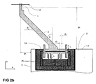
- the MEMS sensor chip 17 according to a preferred embodiment of the invention features a different comb drive configuration as shown in Figure 2b .
- the non-movable electrodes 25 are moved to the same side next to each other also forming a differential comb drive.
- the new configuration is advantageous for reducing the MEMS sensor chip 17 size in y-direction and for wire-bonding the MEMS sensor chip 17 to the substrate 7 by reducing the length of the wires.
- the MEMS sensor chip 17 is mounted onto a substrate 7, which is normally a printed circuit board 7 which also includes the interface IC and the rest of the readout electronics 11.
- the sensor chip is located at the upper edge of the substrate 7 (substrate edge 8) and at the right or the left edge (substrate edge 9).
- the sensor is wire-bonded to the substrate.
- the sensor probe 2 is designed such that it's probe tip 1 is overhanging two sides 8, 9 of the substrate 7 by the distance p x and p y respectively as shown in Figure 2b . This is realized by introducing an angle ⁇ into the MEMS design or by choosing a bent probe shape.
- the values p x and p y can range from single micrometers of to several millimeters. The fact that the sensor probe is overhanging both substrate side 8 and substrate side 9, allows the sensor to be used for a much higher number of applications.
- the sensor is used in combination with an optical microscope or a scanning electron microscope to observe the alignment of the sensor probe tip 1 and the sample
- the capacitive MEMS force sensors are used in combination with a precise micropositioning device such as a micromanipulator.
- the sensor can be mounted in different, adjustable orientations as shown in Fig 4b .
- the way the sensor is mounted on the micromanipulator depends on the desired sensing direction for a certain application. Some measurement tasks require the application of the force to the sample 14 in vertical direction (c-direction). Other applications require the application of the force to the sample 14 in horizontal direction (a-b-plane).
- the sensitive direction 10 of the sensor is aligned with the c-axis.
- the substrate 7 may have a cutout 21 such that the sensor can also be used in the limited space available underneath the microscope lens 12 and above the sample holder 13.
- the sensor is mounted at an angle ⁇ as shown Fig. 4b .
- the angle ⁇ can be altered without changing the sensitive direction 10 which is a great advantage compared to prior art sensor designs since it simplifies the experimental setup, the application of the force in a- direction or b-direction and the interpretation of the measurement data.
- Figure 5a .. 5c compares the prior art sensor design 18 with the sensor proposed according to the invention.
- the sensitive direction of the prior art sensor 22 is parallel to the sensor probe as shown in Fig. 5a .
- the sensor probe is parallel to the long axis of the substrate. This is not the case in the new sensor 23 design shown in Fig. 5b and Fig. 5c .
- the sensitive axis is perpendicular to the long-axis of the sensor package 20 and the probe tip 1.
- the sensor probe of the prior art sensor 18 is overhanging one side of the substrate only. In the new sensor 23 the probe is overhanging two sides 8, 9 of the substrate 7. This is the upper substrate edge 8 and one of the adjacent substrate edges 9 of the upper substrate edge 8.
- This adjacent edge of the substrate 9 can be on the right or left side of the substrate 7.
- the probe is straight, while the probe 2 of the new sensor 23 is tilted at an angle ⁇ as shown in Figure 2b .
- the sensitive direction 10 is perpendicular to the long axis of the substrate 7 (x-axis in Fig. 5a, 5b, 5c .
- the prior art sensor features a sensitive direction parallel to the substrate edge 9 (left or right side), the new sensor features a sensitive direction parallel to substrate edge 8 (upper substrate edge).
- the MEMS sensor chip is located at the edge of two adjacent substrate sides 8, 9.
Landscapes
- Physics & Mathematics (AREA)
- General Physics & Mathematics (AREA)
- Engineering & Computer Science (AREA)
- Power Engineering (AREA)
- Micromachines (AREA)
- Force Measurement Appropriate To Specific Purposes (AREA)
Claims (4)
- Capteur de force capacitif à axe unique à système microélectromécanique (MEMS) pour capter des forces submillinewtoniennes, comprenant :- une sonde de capteur (2) avec une pointe de sonde (1) sur laquelle la force est appliquée,- au moins un entraînement en peigne pour une mesure capacitive (6), et- un substrat (7),caractérisé par la sonde de capteur (2) avec la pointe de capteur (1) qui dépasse (px, py) du substrat de capteur (7) sur deux côtés, adjacents, des bords de substrat (8, 9).
- Capteur de force MEMS capacitif selon la revendication 1, étant précisé que les deux électrodes de condensateurs non mobiles (25) du capteur sont proches l'une de l'autre, formant un entraînement en peigne différentiel en combinaison avec l'électrode commune mobile (24).
- Capteur de force MEMS capacitif selon l'une des revendications 1 à 2, étant précisé qu'un circuit intégré d'interface capacitif (11) se trouve directement sur le substrat (7).
- Capteur de force MEMS capacitif selon l'une des revendications 1 à 3, étant précisé que le capteur est monté sur un micromanipulateur de telle sorte que l'orientation des capteurs dans l'espace puisse être réglée.
Priority Applications (1)
| Application Number | Priority Date | Filing Date | Title |
|---|---|---|---|
| EP12759486.9A EP2764341B1 (fr) | 2011-10-04 | 2012-09-20 | Capteur de force à système microélectromécanique (mems) capacitif sub-millinewton pour essai mécanique sur microscope |
Applications Claiming Priority (3)
| Application Number | Priority Date | Filing Date | Title |
|---|---|---|---|
| EP11183816 | 2011-10-04 | ||
| PCT/EP2012/068539 WO2013050252A1 (fr) | 2011-10-04 | 2012-09-20 | Capteur de force à système microélectromécanique (mems) capacitif sub-millinewton pour essai mécanique sur microscope |
| EP12759486.9A EP2764341B1 (fr) | 2011-10-04 | 2012-09-20 | Capteur de force à système microélectromécanique (mems) capacitif sub-millinewton pour essai mécanique sur microscope |
Publications (2)
| Publication Number | Publication Date |
|---|---|
| EP2764341A1 EP2764341A1 (fr) | 2014-08-13 |
| EP2764341B1 true EP2764341B1 (fr) | 2015-08-19 |
Family
ID=46852039
Family Applications (1)
| Application Number | Title | Priority Date | Filing Date |
|---|---|---|---|
| EP12759486.9A Active EP2764341B1 (fr) | 2011-10-04 | 2012-09-20 | Capteur de force à système microélectromécanique (mems) capacitif sub-millinewton pour essai mécanique sur microscope |
Country Status (4)
| Country | Link |
|---|---|
| US (1) | US8984966B2 (fr) |
| EP (1) | EP2764341B1 (fr) |
| ES (1) | ES2546908T3 (fr) |
| WO (1) | WO2013050252A1 (fr) |
Families Citing this family (7)
| Publication number | Priority date | Publication date | Assignee | Title |
|---|---|---|---|---|
| WO2017124108A2 (fr) * | 2016-01-15 | 2017-07-20 | Vanderbilt University | Dispositifs et procédés pour des mesures de tension et applications de ceux-ci |
| KR102330396B1 (ko) * | 2016-12-02 | 2021-11-24 | 주식회사 로보터스 | 정전 용량형 센서 |
| US11911904B2 (en) | 2020-07-15 | 2024-02-27 | Micron Technology, Inc. | Apparatus and methods for enhanced microelectronic device handling |
| CN113237595B (zh) * | 2021-05-08 | 2022-04-08 | 杭州电子科技大学 | 一种二维解耦力触觉传感器及mems制备方法 |
| CN116973010B (zh) * | 2022-04-23 | 2026-01-16 | 午芯(辽宁省)高科技有限公司 | 竖置极板电容式敏感芯片结构 |
| CN115931185B (zh) * | 2023-01-03 | 2024-06-11 | 歌尔微电子股份有限公司 | 一种电容式微机电传感器 |
| CN116858403A (zh) * | 2023-06-12 | 2023-10-10 | 武汉大学 | 一种微力测量装置和方法 |
Family Cites Families (14)
| Publication number | Priority date | Publication date | Assignee | Title |
|---|---|---|---|---|
| DE4107605C1 (en) | 1991-03-09 | 1992-04-02 | Hommelwerke Gmbh, 7730 Villingen-Schwenningen, De | Sensor for atomic force raster microscope - has opto-electronic distance measurer for ascertaining movement of probe tip at distal end of extendable arm |
| EP0880671A2 (fr) * | 1995-07-20 | 1998-12-02 | Cornell Research Foundation, Inc. | Dispositifs en porte-a-faux de torsion microfabriques pour une detection de force sensible |
| JP3370527B2 (ja) * | 1996-03-08 | 2003-01-27 | セイコーインスツルメンツ株式会社 | 原子間力顕微鏡用プローブとその製造方法および原子間力顕微鏡 |
| JP3260644B2 (ja) * | 1996-12-10 | 2002-02-25 | セイコーインスツルメンツ株式会社 | カンチレバーおよびその製造方法 |
| US6415653B1 (en) * | 1998-03-24 | 2002-07-09 | Olympus Optical Co., Ltd. | Cantilever for use in a scanning probe microscope |
| US6405584B1 (en) * | 1999-10-05 | 2002-06-18 | Agere Systems Guardian Corp. | Probe for scanning probe microscopy and related methods |
| JP2004093352A (ja) * | 2002-08-30 | 2004-03-25 | Seiko Instruments Inc | 極微小多探針プローブの製造方法及び表面特性解析装置 |
| US20040139808A1 (en) | 2003-01-13 | 2004-07-22 | Keller Christopher Guild | Micro force gages and calibration weights |
| US7022976B1 (en) * | 2003-04-02 | 2006-04-04 | Advanced Micro Devices, Inc. | Dynamically adjustable probe tips |
| DE602005005478T2 (de) | 2004-06-09 | 2009-04-23 | ETH Zürich | Mehrachsiger kapazitiver wandler |
| US7726197B2 (en) | 2006-04-26 | 2010-06-01 | Honeywell International Inc. | Force sensor package and method of forming same |
| CA2551191C (fr) | 2006-06-23 | 2016-04-05 | Keekyoung Kim | Micro-pinces electrothermiques avec capteurs de force capacitifs suivant deux axes |
| US7421899B2 (en) * | 2006-07-17 | 2008-09-09 | Agilent Technologies, Inc. | Resonance method for determining the spring constant of scanning probe microscope cantilevers using MEMS actuators |
| WO2010112242A1 (fr) | 2009-03-31 | 2010-10-07 | Femtotools Gmbh | Ensemble capteur de micro-forces pour des mesures électromécaniques inférieures au milli-newton |
-
2012
- 2012-09-20 ES ES12759486.9T patent/ES2546908T3/es active Active
- 2012-09-20 WO PCT/EP2012/068539 patent/WO2013050252A1/fr not_active Ceased
- 2012-09-20 US US14/347,421 patent/US8984966B2/en active Active
- 2012-09-20 EP EP12759486.9A patent/EP2764341B1/fr active Active
Also Published As
| Publication number | Publication date |
|---|---|
| US20140230576A1 (en) | 2014-08-21 |
| WO2013050252A1 (fr) | 2013-04-11 |
| ES2546908T3 (es) | 2015-09-29 |
| EP2764341A1 (fr) | 2014-08-13 |
| US8984966B2 (en) | 2015-03-24 |
Similar Documents
| Publication | Publication Date | Title |
|---|---|---|
| US8984966B2 (en) | Sub-millinewton capacitive MEMS force sensor for mechanical testing on a microscope | |
| EP2960637B1 (fr) | Conception et interface d'un capteur de force à balayage microfabriqué pour une détection combinée de force et de position | |
| EP2310830B1 (fr) | Entraînement de type peigne micro-usiné pour nanoindentation quantitative | |
| Wei et al. | An overview of micro-force sensing techniques | |
| US7921731B2 (en) | Two-axis direct fluid shear stress sensor | |
| KR101477120B1 (ko) | 정전용량형 6축 힘/토크 센서 | |
| US9335240B2 (en) | Method of measuring an interaction force | |
| EP1756591B1 (fr) | Transducteur capacitif multi-axial | |
| Brookhuis et al. | Six-axis force–torque sensor with a large range for biomechanical applications | |
| EP1970714A1 (fr) | Dispositif comportant un détecteur de contact | |
| EP2926111B1 (fr) | Entraînement par peigne micro-usiné pour nano-indentation quantitative | |
| EP3259569B1 (fr) | Capteur de force piézorésistif à axes multiples | |
| CN114383762A (zh) | 基于多梳齿阵列的mems电容式微力传感器及去耦合测试方法 | |
| Adam et al. | An overview of microrobotic systems for microforce sensing | |
| US20140060207A1 (en) | Versatile, flexible, and robust mems/nems sensor for decoupled measuring of three-dimensional forces in air or liquids | |
| Que et al. | A micromachined strain sensor with differential capacitive readout | |
| Park et al. | Capacitive two-dimensional force sensing microcantilever with a conductive tip for characterization of biological samples | |
| EP3489654B1 (fr) | Puce de nano-pénétrateur mems comportant une sonde de pénétrateur et une sonde de référence | |
| Zhang et al. | Design and characterization of a silicon piezoresistive three-axial force sensor for micro-flapping wing MAV applications | |
| Beyeler et al. | A multi-axis mems force-torque sensor for measuring the load on a microrobot actuated by magnetic fields | |
| EP4488653B1 (fr) | Sonde de test de matériaux | |
| Shimizu et al. | A MEMS Device Integrating Multiple Cantilever Displacement Sensors to Evaluate Flat Machined Surfaces | |
| Ignakhin et al. | Capacitive sensors of mechanical strain | |
| Rezazadeh Kalashami et al. | Effect of stress concentration regions on the performance of piezoresistive silicon beams | |
| Wang et al. | Design method of sensors for quantitative mechanical testing of nanomaterials in transmission electron microscopy |
Legal Events
| Date | Code | Title | Description |
|---|---|---|---|
| PUAI | Public reference made under article 153(3) epc to a published international application that has entered the european phase |
Free format text: ORIGINAL CODE: 0009012 |
|
| 17P | Request for examination filed |
Effective date: 20140425 |
|
| AK | Designated contracting states |
Kind code of ref document: A1 Designated state(s): AL AT BE BG CH CY CZ DE DK EE ES FI FR GB GR HR HU IE IS IT LI LT LU LV MC MK MT NL NO PL PT RO RS SE SI SK SM TR |
|
| RIN1 | Information on inventor provided before grant (corrected) |
Inventor name: MUNTWYLER, SIMON Inventor name: DIETZE, WOLFGANG Inventor name: BEYELER, FELIX |
|
| DAX | Request for extension of the european patent (deleted) | ||
| REG | Reference to a national code |
Ref country code: DE Ref legal event code: R079 Ref document number: 602012009847 Country of ref document: DE Free format text: PREVIOUS MAIN CLASS: G01L0005000000 Ipc: G01L0001140000 |
|
| GRAP | Despatch of communication of intention to grant a patent |
Free format text: ORIGINAL CODE: EPIDOSNIGR1 |
|
| RIC1 | Information provided on ipc code assigned before grant |
Ipc: G01L 1/14 20060101AFI20150220BHEP Ipc: G01L 5/00 20060101ALI20150220BHEP Ipc: G01L 5/16 20060101ALI20150220BHEP |
|
| INTG | Intention to grant announced |
Effective date: 20150320 |
|
| GRAS | Grant fee paid |
Free format text: ORIGINAL CODE: EPIDOSNIGR3 |
|
| GRAA | (expected) grant |
Free format text: ORIGINAL CODE: 0009210 |
|
| AK | Designated contracting states |
Kind code of ref document: B1 Designated state(s): AL AT BE BG CH CY CZ DE DK EE ES FI FR GB GR HR HU IE IS IT LI LT LU LV MC MK MT NL NO PL PT RO RS SE SI SK SM TR |
|
| REG | Reference to a national code |
Ref country code: GB Ref legal event code: FG4D |
|
| REG | Reference to a national code |
Ref country code: CH Ref legal event code: EP Ref country code: CH Ref legal event code: NV Representative=s name: HANSJOERG KLEY, CH |
|
| REG | Reference to a national code |
Ref country code: IE Ref legal event code: FG4D |
|
| REG | Reference to a national code |
Ref country code: AT Ref legal event code: REF Ref document number: 744138 Country of ref document: AT Kind code of ref document: T Effective date: 20150915 |
|
| REG | Reference to a national code |
Ref country code: ES Ref legal event code: FG2A Ref document number: 2546908 Country of ref document: ES Kind code of ref document: T3 Effective date: 20150929 |
|
| REG | Reference to a national code |
Ref country code: DE Ref legal event code: R096 Ref document number: 602012009847 Country of ref document: DE |
|
| REG | Reference to a national code |
Ref country code: SE Ref legal event code: TRGR |
|
| REG | Reference to a national code |
Ref country code: NL Ref legal event code: FP |
|
| REG | Reference to a national code |
Ref country code: NO Ref legal event code: T2 Effective date: 20150819 |
|
| REG | Reference to a national code |
Ref country code: LT Ref legal event code: MG4D |
|
| PG25 | Lapsed in a contracting state [announced via postgrant information from national office to epo] |
Ref country code: LV Free format text: LAPSE BECAUSE OF FAILURE TO SUBMIT A TRANSLATION OF THE DESCRIPTION OR TO PAY THE FEE WITHIN THE PRESCRIBED TIME-LIMIT Effective date: 20150819 Ref country code: GR Free format text: LAPSE BECAUSE OF FAILURE TO SUBMIT A TRANSLATION OF THE DESCRIPTION OR TO PAY THE FEE WITHIN THE PRESCRIBED TIME-LIMIT Effective date: 20151120 Ref country code: LT Free format text: LAPSE BECAUSE OF FAILURE TO SUBMIT A TRANSLATION OF THE DESCRIPTION OR TO PAY THE FEE WITHIN THE PRESCRIBED TIME-LIMIT Effective date: 20150819 |
|
| PG25 | Lapsed in a contracting state [announced via postgrant information from national office to epo] |
Ref country code: PT Free format text: LAPSE BECAUSE OF FAILURE TO SUBMIT A TRANSLATION OF THE DESCRIPTION OR TO PAY THE FEE WITHIN THE PRESCRIBED TIME-LIMIT Effective date: 20151221 Ref country code: RS Free format text: LAPSE BECAUSE OF FAILURE TO SUBMIT A TRANSLATION OF THE DESCRIPTION OR TO PAY THE FEE WITHIN THE PRESCRIBED TIME-LIMIT Effective date: 20150819 Ref country code: IS Free format text: LAPSE BECAUSE OF FAILURE TO SUBMIT A TRANSLATION OF THE DESCRIPTION OR TO PAY THE FEE WITHIN THE PRESCRIBED TIME-LIMIT Effective date: 20151219 Ref country code: PL Free format text: LAPSE BECAUSE OF FAILURE TO SUBMIT A TRANSLATION OF THE DESCRIPTION OR TO PAY THE FEE WITHIN THE PRESCRIBED TIME-LIMIT Effective date: 20150819 |
|
| PG25 | Lapsed in a contracting state [announced via postgrant information from national office to epo] |
Ref country code: CZ Free format text: LAPSE BECAUSE OF FAILURE TO SUBMIT A TRANSLATION OF THE DESCRIPTION OR TO PAY THE FEE WITHIN THE PRESCRIBED TIME-LIMIT Effective date: 20150819 Ref country code: SK Free format text: LAPSE BECAUSE OF FAILURE TO SUBMIT A TRANSLATION OF THE DESCRIPTION OR TO PAY THE FEE WITHIN THE PRESCRIBED TIME-LIMIT Effective date: 20150819 Ref country code: DK Free format text: LAPSE BECAUSE OF FAILURE TO SUBMIT A TRANSLATION OF THE DESCRIPTION OR TO PAY THE FEE WITHIN THE PRESCRIBED TIME-LIMIT Effective date: 20150819 Ref country code: EE Free format text: LAPSE BECAUSE OF FAILURE TO SUBMIT A TRANSLATION OF THE DESCRIPTION OR TO PAY THE FEE WITHIN THE PRESCRIBED TIME-LIMIT Effective date: 20150819 |
|
| REG | Reference to a national code |
Ref country code: DE Ref legal event code: R097 Ref document number: 602012009847 Country of ref document: DE |
|
| PG25 | Lapsed in a contracting state [announced via postgrant information from national office to epo] |
Ref country code: RO Free format text: LAPSE BECAUSE OF FAILURE TO SUBMIT A TRANSLATION OF THE DESCRIPTION OR TO PAY THE FEE WITHIN THE PRESCRIBED TIME-LIMIT Effective date: 20150819 Ref country code: MC Free format text: LAPSE BECAUSE OF FAILURE TO SUBMIT A TRANSLATION OF THE DESCRIPTION OR TO PAY THE FEE WITHIN THE PRESCRIBED TIME-LIMIT Effective date: 20150819 |
|
| PLBE | No opposition filed within time limit |
Free format text: ORIGINAL CODE: 0009261 |
|
| STAA | Information on the status of an ep patent application or granted ep patent |
Free format text: STATUS: NO OPPOSITION FILED WITHIN TIME LIMIT |
|
| 26N | No opposition filed |
Effective date: 20160520 |
|
| PG25 | Lapsed in a contracting state [announced via postgrant information from national office to epo] |
Ref country code: SI Free format text: LAPSE BECAUSE OF FAILURE TO SUBMIT A TRANSLATION OF THE DESCRIPTION OR TO PAY THE FEE WITHIN THE PRESCRIBED TIME-LIMIT Effective date: 20150819 |
|
| REG | Reference to a national code |
Ref country code: FR Ref legal event code: PLFP Year of fee payment: 5 |
|
| PG25 | Lapsed in a contracting state [announced via postgrant information from national office to epo] |
Ref country code: MT Free format text: LAPSE BECAUSE OF FAILURE TO SUBMIT A TRANSLATION OF THE DESCRIPTION OR TO PAY THE FEE WITHIN THE PRESCRIBED TIME-LIMIT Effective date: 20150819 |
|
| PG25 | Lapsed in a contracting state [announced via postgrant information from national office to epo] |
Ref country code: HU Free format text: LAPSE BECAUSE OF FAILURE TO SUBMIT A TRANSLATION OF THE DESCRIPTION OR TO PAY THE FEE WITHIN THE PRESCRIBED TIME-LIMIT; INVALID AB INITIO Effective date: 20120920 Ref country code: SM Free format text: LAPSE BECAUSE OF FAILURE TO SUBMIT A TRANSLATION OF THE DESCRIPTION OR TO PAY THE FEE WITHIN THE PRESCRIBED TIME-LIMIT Effective date: 20150819 Ref country code: BG Free format text: LAPSE BECAUSE OF FAILURE TO SUBMIT A TRANSLATION OF THE DESCRIPTION OR TO PAY THE FEE WITHIN THE PRESCRIBED TIME-LIMIT Effective date: 20150819 |
|
| PG25 | Lapsed in a contracting state [announced via postgrant information from national office to epo] |
Ref country code: CY Free format text: LAPSE BECAUSE OF FAILURE TO SUBMIT A TRANSLATION OF THE DESCRIPTION OR TO PAY THE FEE WITHIN THE PRESCRIBED TIME-LIMIT Effective date: 20150819 |
|
| PG25 | Lapsed in a contracting state [announced via postgrant information from national office to epo] |
Ref country code: HR Free format text: LAPSE BECAUSE OF FAILURE TO SUBMIT A TRANSLATION OF THE DESCRIPTION OR TO PAY THE FEE WITHIN THE PRESCRIBED TIME-LIMIT Effective date: 20150819 |
|
| REG | Reference to a national code |
Ref country code: FR Ref legal event code: PLFP Year of fee payment: 6 |
|
| PG25 | Lapsed in a contracting state [announced via postgrant information from national office to epo] |
Ref country code: LU Free format text: LAPSE BECAUSE OF NON-PAYMENT OF DUE FEES Effective date: 20150920 |
|
| REG | Reference to a national code |
Ref country code: AT Ref legal event code: UEP Ref document number: 744138 Country of ref document: AT Kind code of ref document: T Effective date: 20150819 |
|
| PG25 | Lapsed in a contracting state [announced via postgrant information from national office to epo] |
Ref country code: TR Free format text: LAPSE BECAUSE OF FAILURE TO SUBMIT A TRANSLATION OF THE DESCRIPTION OR TO PAY THE FEE WITHIN THE PRESCRIBED TIME-LIMIT Effective date: 20150819 Ref country code: MK Free format text: LAPSE BECAUSE OF FAILURE TO SUBMIT A TRANSLATION OF THE DESCRIPTION OR TO PAY THE FEE WITHIN THE PRESCRIBED TIME-LIMIT Effective date: 20150819 |
|
| REG | Reference to a national code |
Ref country code: FR Ref legal event code: PLFP Year of fee payment: 7 |
|
| PG25 | Lapsed in a contracting state [announced via postgrant information from national office to epo] |
Ref country code: AL Free format text: LAPSE BECAUSE OF FAILURE TO SUBMIT A TRANSLATION OF THE DESCRIPTION OR TO PAY THE FEE WITHIN THE PRESCRIBED TIME-LIMIT Effective date: 20150819 |
|
| PGFP | Annual fee paid to national office [announced via postgrant information from national office to epo] |
Ref country code: IE Payment date: 20180919 Year of fee payment: 7 Ref country code: NO Payment date: 20180920 Year of fee payment: 7 |
|
| PGFP | Annual fee paid to national office [announced via postgrant information from national office to epo] |
Ref country code: PL Payment date: 20180718 Year of fee payment: 7 Ref country code: FI Payment date: 20180918 Year of fee payment: 7 Ref country code: NL Payment date: 20180920 Year of fee payment: 7 Ref country code: BE Payment date: 20180920 Year of fee payment: 7 Ref country code: AT Payment date: 20180918 Year of fee payment: 7 |
|
| PGFP | Annual fee paid to national office [announced via postgrant information from national office to epo] |
Ref country code: ES Payment date: 20181024 Year of fee payment: 7 |
|
| REG | Reference to a national code |
Ref country code: FI Ref legal event code: MAE |
|
| REG | Reference to a national code |
Ref country code: NO Ref legal event code: MMEP |
|
| PG25 | Lapsed in a contracting state [announced via postgrant information from national office to epo] |
Ref country code: SE Free format text: LAPSE BECAUSE OF NON-PAYMENT OF DUE FEES Effective date: 20190921 Ref country code: FI Free format text: LAPSE BECAUSE OF NON-PAYMENT OF DUE FEES Effective date: 20190920 |
|
| REG | Reference to a national code |
Ref country code: SE Ref legal event code: EUG |
|
| REG | Reference to a national code |
Ref country code: NL Ref legal event code: MM Effective date: 20191001 |
|
| PG25 | Lapsed in a contracting state [announced via postgrant information from national office to epo] |
Ref country code: IE Free format text: LAPSE BECAUSE OF NON-PAYMENT OF DUE FEES Effective date: 20190920 Ref country code: NL Free format text: LAPSE BECAUSE OF NON-PAYMENT OF DUE FEES Effective date: 20191001 Ref country code: NO Free format text: LAPSE BECAUSE OF NON-PAYMENT OF DUE FEES Effective date: 20190930 |
|
| REG | Reference to a national code |
Ref country code: BE Ref legal event code: MM Effective date: 20190930 |
|
| REG | Reference to a national code |
Ref country code: AT Ref legal event code: MM01 Ref document number: 744138 Country of ref document: AT Kind code of ref document: T Effective date: 20190920 |
|
| PG25 | Lapsed in a contracting state [announced via postgrant information from national office to epo] |
Ref country code: IT Free format text: LAPSE BECAUSE OF NON-PAYMENT OF DUE FEES Effective date: 20190920 Ref country code: BE Free format text: LAPSE BECAUSE OF NON-PAYMENT OF DUE FEES Effective date: 20190930 |
|
| PG25 | Lapsed in a contracting state [announced via postgrant information from national office to epo] |
Ref country code: AT Free format text: LAPSE BECAUSE OF NON-PAYMENT OF DUE FEES Effective date: 20190920 |
|
| REG | Reference to a national code |
Ref country code: ES Ref legal event code: FD2A Effective date: 20210128 |
|
| PG25 | Lapsed in a contracting state [announced via postgrant information from national office to epo] |
Ref country code: ES Free format text: LAPSE BECAUSE OF NON-PAYMENT OF DUE FEES Effective date: 20190921 |
|
| P01 | Opt-out of the competence of the unified patent court (upc) registered |
Effective date: 20230308 |
|
| REG | Reference to a national code |
Ref country code: CH Ref legal event code: U11 Free format text: ST27 STATUS EVENT CODE: U-0-0-U10-U11 (AS PROVIDED BY THE NATIONAL OFFICE) Effective date: 20251001 |
|
| PGFP | Annual fee paid to national office [announced via postgrant information from national office to epo] |
Ref country code: DE Payment date: 20250915 Year of fee payment: 14 |
|
| PGFP | Annual fee paid to national office [announced via postgrant information from national office to epo] |
Ref country code: GB Payment date: 20250923 Year of fee payment: 14 |
|
| PGFP | Annual fee paid to national office [announced via postgrant information from national office to epo] |
Ref country code: FR Payment date: 20250925 Year of fee payment: 14 |
|
| PGFP | Annual fee paid to national office [announced via postgrant information from national office to epo] |
Ref country code: CH Payment date: 20251001 Year of fee payment: 14 |