EP2764607B1 - Unité de connexion conçue pour le raccordement des enroulements statoriques d'un moteur électrique et moteur électrique - Google Patents
Unité de connexion conçue pour le raccordement des enroulements statoriques d'un moteur électrique et moteur électrique Download PDFInfo
- Publication number
- EP2764607B1 EP2764607B1 EP12745624.2A EP12745624A EP2764607B1 EP 2764607 B1 EP2764607 B1 EP 2764607B1 EP 12745624 A EP12745624 A EP 12745624A EP 2764607 B1 EP2764607 B1 EP 2764607B1
- Authority
- EP
- European Patent Office
- Prior art keywords
- bolts
- electric motor
- cable lugs
- bolt
- spacer
- Prior art date
- Legal status (The legal status is an assumption and is not a legal conclusion. Google has not performed a legal analysis and makes no representation as to the accuracy of the status listed.)
- Active
Links
Images

Classifications
-
- H—ELECTRICITY
- H02—GENERATION; CONVERSION OR DISTRIBUTION OF ELECTRIC POWER
- H02K—DYNAMO-ELECTRIC MACHINES
- H02K3/00—Details of windings
- H02K3/46—Fastening of windings on the stator or rotor structure
- H02K3/50—Fastening of winding heads, equalising connectors, or connections thereto
Definitions
- the invention relates to a connection unit for the interconnection of the stator windings of an electric motor and an electric motor.
- stator winding leads are led out with their end portions in a terminal box of the associated electric motor, where they are connected to electrical supply lines and / or the electrical interconnection, ie interconnection of the stator windings in star connection or delta connection is performed.
- connection device for an electrical machine From the WO 2006/018396 A1 is known a connection device for an electrical machine.
- From the DE 1 282 157 is a method for producing a compact by a molding compound closed electric small motor known.
- the invention is therefore the object of developing an electric motor compact.
- the object is achieved in the electric motor according to the features indicated in claim 1.
- connection unit for the interconnection of the stator windings of an electric motor is that, the ends of the Statorwicklungs einen are connected with cable lugs, in particular non-positively connected and / or welded, wherein the cable lugs are connected to respective bolts, in particular wherein the bolts are inserted through a recess arranged in the cable lug, wherein the bolts are each connected to a spacer, in particular screw-connected, wherein the distance between next adjacent bolts, in particular along the spacer and / or thus the distance between the connecting regions of the respective bolt with the spacer, is in each case greater than the radial extent of the spacer, in particular so that the bolts are arranged on the spacer in a row and each spaced from each other.
- the advantage here is that the electrical connections are not led out of the stator but within the potting of the stator, the stator windings with the Bolt, so connecting means to be connected.
- the interconnection is carried out within the potting compound and thus well protected, in particular mechanically stabilized and electrically well insulated and effectively cooled with the use of potting compound with good thermal conductivity.
- the interconnection and the connection with connection means thus requires no additional space.
- the spacer is executed substantially linear and / or elongated.
- the advantage here is that the interconnection with terminal unit in the Statorvergussmasse in the axial region of the winding heads, ie deflection of the stator windings, can be arranged and thus space is optimally exploitable. Because in the winding heads between the winding heads and the rotor enough space is available.
- the rotor can indeed be equipped with active parts or reactive parts, such as short-circuit cage or permanent magnets, but these are necessary only in the axial region of the laminated stator core.
- the spacer is in one piece and / or made of electrically insulating material, in particular of plastic, of an epoxy resin-containing part or ceramic.
- electrically insulating material in particular of plastic, of an epoxy resin-containing part or ceramic.
- the cable lugs are attached in each case by means of one of their punched-out recesses on the bolts.
- the advantage here is that a form-fitting and thus secure connection is made in the radial direction.
- a plurality of parallel aligned cable lugs are connected to one or more bolts, in particular wherein between the cable lugs a spacer sleeve, in particular a metallic running spacer sleeve, is arranged on the bolt, in particular, wherein the cable shoes connected to first ends of the stator windings are connected to or on the bolts.
- a plurality of non-aligned cable lugs are connected to a bolt provided for forming a star point, in particular wherein on the bolt connected to the second ends of the stator windings cable shoes are connected.
- the bolt provided for forming a star point is axially, in particular in Bolzenachscardi and / or in Rotorachscardi the electric motor, less extensive than the other bolts.
- the advantage here is that the star point is completely providable in the potting compound and thus is electrically isolated from the environment.
- the cable lugs are attached to the spacer and / or with the spacer sleeve by means screwed onto threaded portions of the bolt nuts.
- the cable lugs, the bolts and the spacer sleeve made of electrically conductive material, in particular made of metallic material.
- the advantage here is that easily manufacturable sheet metal parts, in particular stamped and bent parts, can be used.
- connection unit is arranged in potting compound such that the bolt provided for forming a neutral point does not protrude from the potting compound and that the other bolts at least partially protrude from the potting compound, in particular, wherein all cable lugs are cast in potting compound.
- the advantage here is that a mechanically stable and electrically insulated design is possible.
- electrical lines for supplying the electric motor are electrically connected to the end regions of the bolts projecting from the casting compound,
- the lines are provided with cable lugs, which are fastened by nuts on the bolts: It is advantageous that supply lines are easily connectable, in particular by means of the lines connected and plugged and bolted lugs.
- FIG. 2 a stator of an electric motor is shown in an oblique view, wherein the connection unit according to the invention is encapsulated integrated.
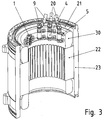
- FIG. 3 is the stator off FIG. 2 shown cut.
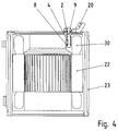
- FIG. 4 In the FIG. 4 is shown cross section through the stator.
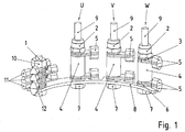
- the electric motor according to the invention has a connection unit which has an elongate spacer 8 on which four bolts are arranged one behind the other.
- the spacer thus receives a series of bolts and therefore absorbs a quasi one-dimensional arrangement of bolts (1, 9).
- the electric motor has a three-phase winding with stator windings (U, V, W), the respective ends of which are guided on cable lugs (5, 11) and are electrically connected thereto, in particular by welding or soldering.
- a first bolt 1 is provided to form a star point.
- the first ends of the stator windings (U, V, W) are connected to the cable lugs 11 and the respective second ends of the stator windings to the cable lugs 5, which secured to the other bolts (1, 9) by means of the spacer 8 spaced bolts 9 are.
- the cable lugs (11, 5) designed as a ring cable lugs and attached to the respective bolt (1, 9) and / or threaded.
- the spacer 8 For receiving the respective bolt (1, 9), the spacer 8 has a respective recess, in particular a hole, so that the bolt (1, 9) is guided. From the underside a nut (7, 12) is screwed onto a threaded portion of the respective bolt (1, 9).
- Cable lugs, spacer, bolts, nuts and washers are preferably made of metal.
- the spacer 8 is made of an electrically insulating material, such as plastic. But it is also usable ceramic.
- each bolt a threaded portion is also provided, on which a respective nut (2, 10) is screwed, so that between this nut (2, 10) and the nut screwed on the underside (7, 12), the spacer sleeve 4, the washers and the Jardinschuhring Schemee are pressed together with the spacer 8 in Bolzenachsraum. Transverse to the Bolzenachsplatz said parts are positively held by passing through their hole area of the bolt.
- the bolt 1 Since the neutral point is not led out of the stator area, the bolt 1, together with the cable lugs 11 connected to it, is encapsulated in potting compound.
- the cable lugs 5 of the bolts 9 are encapsulated in the potting compound 21, but the upper end regions of the bolts 9 protrude from the potting compound 21.
- the cable lugs (11, 5) on the bolts (1, 9) are kept stable against mechanical vibrations.
- the potting compound 21 thus stabilizes and also improves the electrical insulation. In particular, the star point is completely potted, so it does not look out of the potting compound 21.
- stator windings are provided around teeth of the stator lamination stack 22, deflecting regions being arranged in the axial end regions of the stator winding, ie winding heads 30.
- the winding heads 30 are at least partially surrounded by the potting compound 21 and thus mechanically stabilized and electrically insulated.
- a potting compound 21 thermally conductive material is selectable, so that the heat of the winding heads 30 is discharged directly to the inside of the housing part 23 and from the housing part to the cooling medium.
- the electrical leads 20 for the phases (U, V, W) of the three-phase winding of the electric motor have at their end portions of cable lugs, which are plugged onto the bolts 9 and screwed in turn by means of nuts.
- the latter has a greater distance from the spacer 8 than the former.
- Spacer 8 extends substantially parallel to the surface, so the end face, the potting compound 21.
- the motor axis direction is aligned in the direction of gravity during manufacture of the motor, so that the potting compound from above into the area of the winding heads and the connection unit in the surrounded by the housing part 23 Area.
- the forming surface of the potting compound covers the stud 1 of the star point completely and the other bolts 9 partially, the cable lugs are potted. Only the connection areas, ie a respective end area of the respective bolt 9 still looks out of the potting compound and also has a threaded section there.
- connection unit covers in the axial direction a portion of the area covered by the winding heads 30 axial region.
- the stator has a plurality, in particular four, coils connected in parallel, so that in each case four stator winding lines are to be connected to each pin 9.
- two pairs of cable lugs 5 are arranged on each bolt 9, wherein a pair is formed by two mutually rotated by 180 ° arranged cable lugs 5.
- the ring areas of the two cable lugs 5 in this case touch each other.
- the cable lugs 5 on each bolt are aligned in parallel, since thus the most compact motor can be produced. Because the Statorwicklungstechnische are introduced from a shallow angle approximately tangentially in the cable lugs 5. However, this is only possible through the spacer sleeve 4. Because the pairs must be spaced sufficiently far in the axial direction to bring the stator leads to be inserted at a respective pin 9 in parallel. Without spacers 4, the cable lugs 5 would have to be arranged on the pin 9 rotated by an angular amount to each other, but this would take in the radial direction an increased space and thus would allow only a smaller rotor diameter of the electric motor. With the spacer sleeve 4 so a parallel insertion of the stator is possible and thus a larger rotor diameter.
- the radial inner edge of the spacer 8 is circular.
- the radial extent is increased in those areas in which the bolts 9 are connected, since there is a sufficiently large hole for insertion of the bolt is provided and the associated annular wall thickness is sufficiently selected.
- the nuts 2 are only partially encapsulated by the potting compound.
- the nuts 2 are designed as open cap nuts. This means that they have an axial portion, which is designed as a hexagon area. This is followed axially by a hat area. This is exemplary here from a cylindrical and subsequently bevelled, in particular frusto-conical, executed area composed.
- This bevelled area has the advantage that it can be provided with an O-ring seal, can be attached to a mold shell. In this way, in the production so a form is tightly connected to the nuts 2, so that the potting compound is pourable into the winding head region and the end face of the nuts 2 protrudes from the potting compound.
- On the front side of the cable lugs of the electrical supply lines are then placed and pressed by means of other nuts against the end face of the nuts 2.
- the spacer sleeve 4 thus causes on the one hand a spacing of the fixed to a respective bolt two pairs of cable lugs 5 and on the other hand, the mother 2, in particular their end face, placed at a greater distance to the spacer 8 than the axially far-most end of the bolt to the neutral point formation ,
- the spacer or the plane which contains the connecting regions between the spacer and the bolt extends parallel to the visible surface of the potting compound, that is to say the axial end face of the potting compound.
Landscapes
- Engineering & Computer Science (AREA)
- Power Engineering (AREA)
- Insulation, Fastening Of Motor, Generator Windings (AREA)
Claims (10)
- Moteur électrique équipé d'une unité de raccordement en vue de la mise en circuit des enroulements statoriques (U, V, W) dudit moteur électrique,
les extrémités des conducteurs desdits enroulements statoriques étant connectées à des cosses de câblage (5, 11), notamment par engagement positif et/ou par jonction soudée, les cosses de câblage (5, 11) étant reliées à des boulons (1, 9) respectifs, sachant notamment que lesdits boulons sont emboîtés à travers un évidement pratiqué dans la cosse de câblage,
lesdites cosses de câblage étant noyées dans de la masse de scellement (21),
lesdits boulons étant reliés, notamment par vissage, à un élément d'espacement (8) respectif,
la distance séparant des boulons voisins les plus rapprochés, en particulier le long de l'élément d'espacement, et/ou, par conséquent, la distance séparant les zones de liaison du boulon considéré avec ledit élément d'espacement, étant respectivement supérieure(s) à l'étendue radiale dudit élément d'espacement,
en particulier de façon telle que lesdits boulons soient agencés en une rangée sur ledit élément d'espacement, et soient respectivement distants les uns des autres,
ledit élément d'espacement (8) étant réalisé d'un seul tenant et/ou en un matériau électriquement isolant, notamment en matière plastique, en une pièce munie de résine époxy, ou en céramique,
les cosses de câblage étant respectivement emboîtées, sur les boulons, au moyen de l'un de leurs évidements ménagés par poinçonnage,
sachant que plusieurs cosses de câblage (11), non orientées parallèlement, sont reliées à un boulon (1) prévu pour former un point neutre,
sachant notamment que les cosses de câblage, connectées à des secondes extrémités des enroulements statoriques, sont reliées audit boulon,
ladite unité de raccordement étant disposée dans de la masse de scellement (21) d'une manière telle que ledit boulon (1), prévu pour former un point neutre, ne dépasse pas au-delà de la masse de scellement (21) et que les autres boulons (9) soient, au moins partiellement, en saillie au-delà de ladite masse de scellement. - Moteur électrique selon la revendication 1,
caractérisé par le fait que
l'élément d'espacement offre, pour l'essentiel, une réalisation linéaire et/ou longiforme. - Moteur électrique selon au moins l'une des revendications précédentes,
caractérisé par le fait que
plusieurs cosses de câblage, orientées parallèlement, sont reliées à un ou plusieurs boulon(s),
sachant notamment qu'une douille d'espacement, en particulier une douille d'espacement de réalisation métallique, est implantée sur le boulon entre lesdites cosses de câblage, sachant notamment que les cosses de câblage, connectées à des premières extrémités des enroulements statoriques, sont reliées audit ou auxdits boulon(s). - Moteur électrique selon au moins l'une des revendications précédentes,
caractérisé par le fait que
le boulon, prévu pour former un point neutre, présente une étendue moindre que celle des autres boulons dans le sens axial, en particulier dans la direction axiale des boulons et/ou dans la direction axiale du rotor dudit moteur électrique. - Moteur électrique selon au moins l'une des revendications précédentes,
caractérisé par le fait que
les cosses de câblage sont fixées à l'élément d'espacement, et/ou à la douille d'espacement, au moyen d'écrous vissés sur des régions filetées des boulons. - Moteur électrique selon au moins l'une des revendications précédentes,
caractérisé par le fait que
les cosses de câblage orientées parallèlement et fixées à un boulon considéré, et les extrémités des conducteurs des enroulements statoriques qui pénètrent dans lesdites cosses, pointent tangentiellement par rapport à la direction périphérique. - Moteur électrique selon au moins l'une des revendications précédentes,
caractérisé par le fait que
les cosses de câblage, les boulons et la douille d'espacement sont fabriqués en un matériau électriquement conducteur, notamment en un matériau métallique. - Moteur électrique selon au moins l'une des revendications précédentes,
caractérisé par le fait que
des conducteurs électriques, dévolus à l'alimentation dudit moteur électrique, sont connectés électriquement aux régions extrêmes des boulons qui font saillie au-delà de la masse de scellement,
sachant notamment que lesdits conducteurs sont pourvus de cosses de câblage fixées sur lesdits boulons au moyen d'écrous. - Moteur électrique selon au moins l'une des revendications précédentes,
caractérisé par le fait que
l'unité de raccordement est disposée dans la région axiale d'une tête d'enroulement, c'est-à-dire, en particulier, d'une zone de déviation d'un enroulement statorique,
en particulier entre le rotor et ladite tête d'enroulement, à l'intérieur de la masse de scellement qui entoure également les enroulements statoriques. - Moteur électrique selon au moins l'une des revendications précédentes,
caractérisé par le fait que
les écrous comportent une région biseautée dédiée à la mise en applique d'une garniture d'étanchement, lors du déversement d'une masse de scellement dans un moule,
sachant notamment que ladite région biseautée n'est pas noyée dans de la masse de scellement,
sachant notamment que lesdits écrous sont réalisés en tant que capuchons taraudés de type ouvert.
Applications Claiming Priority (2)
| Application Number | Priority Date | Filing Date | Title |
|---|---|---|---|
| DE201110115110 DE102011115110B4 (de) | 2011-10-07 | 2011-10-07 | Anschlusseinheit für die Verschaltung der Statorwicklungen eines Elektromotors und Elektromotor |
| PCT/EP2012/003164 WO2013050093A2 (fr) | 2011-10-07 | 2012-07-26 | Unité de connexion conçue pour le raccordement des enroulements statoriques d'un moteur électrique et moteur électrique |
Publications (2)
| Publication Number | Publication Date |
|---|---|
| EP2764607A2 EP2764607A2 (fr) | 2014-08-13 |
| EP2764607B1 true EP2764607B1 (fr) | 2016-05-11 |
Family
ID=46640624
Family Applications (1)
| Application Number | Title | Priority Date | Filing Date |
|---|---|---|---|
| EP12745624.2A Active EP2764607B1 (fr) | 2011-10-07 | 2012-07-26 | Unité de connexion conçue pour le raccordement des enroulements statoriques d'un moteur électrique et moteur électrique |
Country Status (3)
| Country | Link |
|---|---|
| EP (1) | EP2764607B1 (fr) |
| DE (1) | DE102011115110B4 (fr) |
| WO (1) | WO2013050093A2 (fr) |
Cited By (1)
| Publication number | Priority date | Publication date | Assignee | Title |
|---|---|---|---|---|
| DE102024112537A1 (de) | 2024-05-03 | 2025-11-06 | Dr. Ing. H.C. F. Porsche Aktiengesellschaft | Statoranordnung und Verfahren zur Herstellung |
Families Citing this family (2)
| Publication number | Priority date | Publication date | Assignee | Title |
|---|---|---|---|---|
| DE102020129828A1 (de) | 2020-11-12 | 2022-05-12 | Dr. Ing. H.C. F. Porsche Aktiengesellschaft | Stator einer elektrischen Maschine |
| DE102023201466A1 (de) * | 2023-02-21 | 2024-08-22 | Zf Friedrichshafen Ag | Elektromotor mit einem Stator mit Hairpin-Wicklungssystem und einer stabilisierten Verschaltungsanordnung |
Family Cites Families (11)
| Publication number | Priority date | Publication date | Assignee | Title |
|---|---|---|---|---|
| DE1282157B (de) * | 1963-12-05 | 1968-11-07 | Licentia Gmbh | Verfahren zur Herstellung eines durch eine Gussmasse allseitig geschlossenen elektrischen Kleinmotors |
| DE1934897A1 (de) * | 1969-07-10 | 1971-01-14 | Krupp Gmbh | Staender einer elektrischen Maschine |
| DE7900143U1 (de) * | 1979-01-04 | 1979-03-29 | Brown, Boveri & Cie Ag, 6800 Mannheim | Klemmenplatte fuer explosionsgeschuetzte motoren |
| JPS6096147A (ja) * | 1983-10-28 | 1985-05-29 | Fanuc Ltd | 交流電機 |
| JP2002199644A (ja) * | 2000-12-28 | 2002-07-12 | Aisin Aw Co Ltd | 3相モータ |
| DE10239935A1 (de) * | 2002-08-30 | 2004-03-11 | Daimlerchrysler Ag | Verfahren zur Herstellung der Verbindungen zwischen den Enden der Wicklungen des Stators einer elektrischen Maschine und externen Leitern und zwischen dem Statorblechpaket und einem Maschinengehäuse und elektrischen Maschine mit nach dem Verfahren hergestellten Verbindungen |
| JP4046283B2 (ja) * | 2003-07-01 | 2008-02-13 | 三菱電機株式会社 | 回転電機 |
| DE102004027653B4 (de) * | 2003-09-02 | 2023-05-17 | Sew-Eurodrive Gmbh & Co Kg | Elektromotor |
| DE102004039682A1 (de) * | 2004-08-16 | 2006-03-30 | Siemens Ag | Anschlussvorrichtung für eine elektrische Maschine |
| JP4915241B2 (ja) * | 2007-01-10 | 2012-04-11 | トヨタ自動車株式会社 | 回転電機における固定子のリード線端末の取付構造 |
| DE102007027459B4 (de) * | 2007-06-14 | 2010-04-29 | Siemens Ag | Klemmenbrett |
-
2011
- 2011-10-07 DE DE201110115110 patent/DE102011115110B4/de active Active
-
2012
- 2012-07-26 EP EP12745624.2A patent/EP2764607B1/fr active Active
- 2012-07-26 WO PCT/EP2012/003164 patent/WO2013050093A2/fr not_active Ceased
Cited By (1)
| Publication number | Priority date | Publication date | Assignee | Title |
|---|---|---|---|---|
| DE102024112537A1 (de) | 2024-05-03 | 2025-11-06 | Dr. Ing. H.C. F. Porsche Aktiengesellschaft | Statoranordnung und Verfahren zur Herstellung |
Also Published As
| Publication number | Publication date |
|---|---|
| DE102011115110A1 (de) | 2013-04-11 |
| EP2764607A2 (fr) | 2014-08-13 |
| WO2013050093A2 (fr) | 2013-04-11 |
| DE102011115110B4 (de) | 2015-03-26 |
| WO2013050093A3 (fr) | 2014-07-03 |
Similar Documents
| Publication | Publication Date | Title |
|---|---|---|
| DE102015200095B4 (de) | Stator für eine elektrische Maschine und Verfahren zum Herstellen eines solchen | |
| EP1947347B1 (fr) | Unité de pompage | |
| DE112010006096B4 (de) | Stator und mit diesem Stator ausgerüstete rotierende elektrische Maschine | |
| EP2609674B1 (fr) | Dispositif de connexion et moteur électrique pourvu d'un tel dispositif de connexion | |
| EP3906609B1 (fr) | Machine électrique | |
| DE112016001697B4 (de) | Stator für rotierende elektrische Maschine | |
| DE102012024581A1 (de) | Elektromotor mit einem Stator und Verfahren zur Herstellung eines Elektromotors | |
| EP3824528B1 (fr) | Moteur électrique comprenant une unité de câblage et procédé de réalisation d'un moteur électrique comprenant une unité de câblage | |
| EP2764607B1 (fr) | Unité de connexion conçue pour le raccordement des enroulements statoriques d'un moteur électrique et moteur électrique | |
| DE112016001848T5 (de) | Elektrische Verbindungsvorrichtung für eine elektrische Rotationsmaschine und korrespondierende elektrische Rotationsmaschine | |
| WO2012175476A2 (fr) | Support de tête de bobine pour stator d'une machine électrique | |
| DE102004030721B3 (de) | Elektrische Maschine, insbesondere Spaltrohrmotor für eine Umwälzpumpe | |
| EP2750268A1 (fr) | Groupe motopompe | |
| DE102016222614B4 (de) | Stator einer elektrischen Maschine, eine elektrische Maschine, sowie Verfahren zum Herstellen einer solchen | |
| DE102011078026A1 (de) | Schaltungsträger für die Verkabelung der Zahnspulenwicklungen eines Stators einer elektrischen Maschine und Bausatz, enthaltend einen solchen Schaltungsträger | |
| DE102004027653B4 (de) | Elektromotor | |
| EP4300784A1 (fr) | Dispositif stator pour une machine électrique et entraînement électrique pour un véhicule | |
| DE102010005767B4 (de) | Umrichtermotor | |
| DE102008064500A1 (de) | Elektrische Maschine mit Abstützung der Wicklungsschaltung am Statorblechpaket | |
| EP3824530A1 (fr) | Moteur électrique comprenant une unité de câblage et procédé de réalisation d'un moteur électrique comprenant une unité de câblage | |
| WO2023143962A1 (fr) | Stator d'un moteur électrique | |
| EP1665501B1 (fr) | Moteur électrique | |
| WO2022172138A1 (fr) | Moteur électrique à couplage à baïonnette entre stator et unité de barre omnibus | |
| EP2807730A2 (fr) | Transmission pourvue d'une partie carter centrale | |
| WO2009083143A1 (fr) | Support d'enroulement pour une machine électrique |
Legal Events
| Date | Code | Title | Description |
|---|---|---|---|
| PUAI | Public reference made under article 153(3) epc to a published international application that has entered the european phase |
Free format text: ORIGINAL CODE: 0009012 |
|
| 17P | Request for examination filed |
Effective date: 20140425 |
|
| AK | Designated contracting states |
Kind code of ref document: A2 Designated state(s): AL AT BE BG CH CY CZ DE DK EE ES FI FR GB GR HR HU IE IS IT LI LT LU LV MC MK MT NL NO PL PT RO RS SE SI SK SM TR |
|
| AX | Request for extension of the european patent |
Extension state: BA ME |
|
| R17P | Request for examination filed (corrected) |
Effective date: 20150105 |
|
| RBV | Designated contracting states (corrected) |
Designated state(s): AL AT BE BG CH CY CZ DE DK EE ES FI FR GB GR HR HU IE IS IT LI LT LU LV MC MK MT NL NO PL PT RO RS SE SI SK SM TR |
|
| DAX | Request for extension of the european patent (deleted) | ||
| GRAP | Despatch of communication of intention to grant a patent |
Free format text: ORIGINAL CODE: EPIDOSNIGR1 |
|
| INTG | Intention to grant announced |
Effective date: 20151204 |
|
| GRAS | Grant fee paid |
Free format text: ORIGINAL CODE: EPIDOSNIGR3 |
|
| GRAA | (expected) grant |
Free format text: ORIGINAL CODE: 0009210 |
|
| AK | Designated contracting states |
Kind code of ref document: B1 Designated state(s): AL AT BE BG CH CY CZ DE DK EE ES FI FR GB GR HR HU IE IS IT LI LT LU LV MC MK MT NL NO PL PT RO RS SE SI SK SM TR |
|
| REG | Reference to a national code |
Ref country code: GB Ref legal event code: FG4D Free format text: NOT ENGLISH |
|
| REG | Reference to a national code |
Ref country code: CH Ref legal event code: EP |
|
| REG | Reference to a national code |
Ref country code: AT Ref legal event code: REF Ref document number: 799360 Country of ref document: AT Kind code of ref document: T Effective date: 20160515 |
|
| REG | Reference to a national code |
Ref country code: FR Ref legal event code: PLFP Year of fee payment: 5 |
|
| REG | Reference to a national code |
Ref country code: IE Ref legal event code: FG4D Free format text: LANGUAGE OF EP DOCUMENT: GERMAN |
|
| REG | Reference to a national code |
Ref country code: DE Ref legal event code: R096 Ref document number: 502012007075 Country of ref document: DE |
|
| REG | Reference to a national code |
Ref country code: LT Ref legal event code: MG4D |
|
| REG | Reference to a national code |
Ref country code: NL Ref legal event code: MP Effective date: 20160511 |
|
| PG25 | Lapsed in a contracting state [announced via postgrant information from national office to epo] |
Ref country code: FI Free format text: LAPSE BECAUSE OF FAILURE TO SUBMIT A TRANSLATION OF THE DESCRIPTION OR TO PAY THE FEE WITHIN THE PRESCRIBED TIME-LIMIT Effective date: 20160511 Ref country code: NO Free format text: LAPSE BECAUSE OF FAILURE TO SUBMIT A TRANSLATION OF THE DESCRIPTION OR TO PAY THE FEE WITHIN THE PRESCRIBED TIME-LIMIT Effective date: 20160811 Ref country code: NL Free format text: LAPSE BECAUSE OF FAILURE TO SUBMIT A TRANSLATION OF THE DESCRIPTION OR TO PAY THE FEE WITHIN THE PRESCRIBED TIME-LIMIT Effective date: 20160511 Ref country code: LT Free format text: LAPSE BECAUSE OF FAILURE TO SUBMIT A TRANSLATION OF THE DESCRIPTION OR TO PAY THE FEE WITHIN THE PRESCRIBED TIME-LIMIT Effective date: 20160511 |
|
| PG25 | Lapsed in a contracting state [announced via postgrant information from national office to epo] |
Ref country code: ES Free format text: LAPSE BECAUSE OF FAILURE TO SUBMIT A TRANSLATION OF THE DESCRIPTION OR TO PAY THE FEE WITHIN THE PRESCRIBED TIME-LIMIT Effective date: 20160511 Ref country code: RS Free format text: LAPSE BECAUSE OF FAILURE TO SUBMIT A TRANSLATION OF THE DESCRIPTION OR TO PAY THE FEE WITHIN THE PRESCRIBED TIME-LIMIT Effective date: 20160511 Ref country code: LV Free format text: LAPSE BECAUSE OF FAILURE TO SUBMIT A TRANSLATION OF THE DESCRIPTION OR TO PAY THE FEE WITHIN THE PRESCRIBED TIME-LIMIT Effective date: 20160511 Ref country code: GR Free format text: LAPSE BECAUSE OF FAILURE TO SUBMIT A TRANSLATION OF THE DESCRIPTION OR TO PAY THE FEE WITHIN THE PRESCRIBED TIME-LIMIT Effective date: 20160812 Ref country code: PT Free format text: LAPSE BECAUSE OF FAILURE TO SUBMIT A TRANSLATION OF THE DESCRIPTION OR TO PAY THE FEE WITHIN THE PRESCRIBED TIME-LIMIT Effective date: 20160912 Ref country code: SE Free format text: LAPSE BECAUSE OF FAILURE TO SUBMIT A TRANSLATION OF THE DESCRIPTION OR TO PAY THE FEE WITHIN THE PRESCRIBED TIME-LIMIT Effective date: 20160511 Ref country code: HR Free format text: LAPSE BECAUSE OF FAILURE TO SUBMIT A TRANSLATION OF THE DESCRIPTION OR TO PAY THE FEE WITHIN THE PRESCRIBED TIME-LIMIT Effective date: 20160511 |
|
| PG25 | Lapsed in a contracting state [announced via postgrant information from national office to epo] |
Ref country code: IT Free format text: LAPSE BECAUSE OF FAILURE TO SUBMIT A TRANSLATION OF THE DESCRIPTION OR TO PAY THE FEE WITHIN THE PRESCRIBED TIME-LIMIT Effective date: 20160511 Ref country code: BE Free format text: LAPSE BECAUSE OF NON-PAYMENT OF DUE FEES Effective date: 20160731 |
|
| PG25 | Lapsed in a contracting state [announced via postgrant information from national office to epo] |
Ref country code: CZ Free format text: LAPSE BECAUSE OF FAILURE TO SUBMIT A TRANSLATION OF THE DESCRIPTION OR TO PAY THE FEE WITHIN THE PRESCRIBED TIME-LIMIT Effective date: 20160511 Ref country code: RO Free format text: LAPSE BECAUSE OF FAILURE TO SUBMIT A TRANSLATION OF THE DESCRIPTION OR TO PAY THE FEE WITHIN THE PRESCRIBED TIME-LIMIT Effective date: 20160511 Ref country code: SK Free format text: LAPSE BECAUSE OF FAILURE TO SUBMIT A TRANSLATION OF THE DESCRIPTION OR TO PAY THE FEE WITHIN THE PRESCRIBED TIME-LIMIT Effective date: 20160511 Ref country code: EE Free format text: LAPSE BECAUSE OF FAILURE TO SUBMIT A TRANSLATION OF THE DESCRIPTION OR TO PAY THE FEE WITHIN THE PRESCRIBED TIME-LIMIT Effective date: 20160511 Ref country code: DK Free format text: LAPSE BECAUSE OF FAILURE TO SUBMIT A TRANSLATION OF THE DESCRIPTION OR TO PAY THE FEE WITHIN THE PRESCRIBED TIME-LIMIT Effective date: 20160511 |
|
| REG | Reference to a national code |
Ref country code: DE Ref legal event code: R097 Ref document number: 502012007075 Country of ref document: DE |
|
| PG25 | Lapsed in a contracting state [announced via postgrant information from national office to epo] |
Ref country code: SM Free format text: LAPSE BECAUSE OF FAILURE TO SUBMIT A TRANSLATION OF THE DESCRIPTION OR TO PAY THE FEE WITHIN THE PRESCRIBED TIME-LIMIT Effective date: 20160511 Ref country code: PL Free format text: LAPSE BECAUSE OF FAILURE TO SUBMIT A TRANSLATION OF THE DESCRIPTION OR TO PAY THE FEE WITHIN THE PRESCRIBED TIME-LIMIT Effective date: 20160511 |
|
| REG | Reference to a national code |
Ref country code: CH Ref legal event code: PL |
|
| PLBE | No opposition filed within time limit |
Free format text: ORIGINAL CODE: 0009261 |
|
| STAA | Information on the status of an ep patent application or granted ep patent |
Free format text: STATUS: NO OPPOSITION FILED WITHIN TIME LIMIT |
|
| PG25 | Lapsed in a contracting state [announced via postgrant information from national office to epo] |
Ref country code: MC Free format text: LAPSE BECAUSE OF FAILURE TO SUBMIT A TRANSLATION OF THE DESCRIPTION OR TO PAY THE FEE WITHIN THE PRESCRIBED TIME-LIMIT Effective date: 20160511 |
|
| 26N | No opposition filed |
Effective date: 20170214 |
|
| PG25 | Lapsed in a contracting state [announced via postgrant information from national office to epo] |
Ref country code: CH Free format text: LAPSE BECAUSE OF NON-PAYMENT OF DUE FEES Effective date: 20160731 Ref country code: LI Free format text: LAPSE BECAUSE OF NON-PAYMENT OF DUE FEES Effective date: 20160731 |
|
| REG | Reference to a national code |
Ref country code: IE Ref legal event code: MM4A |
|
| PG25 | Lapsed in a contracting state [announced via postgrant information from national office to epo] |
Ref country code: SI Free format text: LAPSE BECAUSE OF FAILURE TO SUBMIT A TRANSLATION OF THE DESCRIPTION OR TO PAY THE FEE WITHIN THE PRESCRIBED TIME-LIMIT Effective date: 20160511 |
|
| REG | Reference to a national code |
Ref country code: FR Ref legal event code: PLFP Year of fee payment: 6 |
|
| PG25 | Lapsed in a contracting state [announced via postgrant information from national office to epo] |
Ref country code: IE Free format text: LAPSE BECAUSE OF NON-PAYMENT OF DUE FEES Effective date: 20160726 |
|
| PG25 | Lapsed in a contracting state [announced via postgrant information from national office to epo] |
Ref country code: LU Free format text: LAPSE BECAUSE OF NON-PAYMENT OF DUE FEES Effective date: 20160726 |
|
| PG25 | Lapsed in a contracting state [announced via postgrant information from national office to epo] |
Ref country code: HU Free format text: LAPSE BECAUSE OF FAILURE TO SUBMIT A TRANSLATION OF THE DESCRIPTION OR TO PAY THE FEE WITHIN THE PRESCRIBED TIME-LIMIT; INVALID AB INITIO Effective date: 20120726 |
|
| REG | Reference to a national code |
Ref country code: FR Ref legal event code: PLFP Year of fee payment: 7 |
|
| PG25 | Lapsed in a contracting state [announced via postgrant information from national office to epo] |
Ref country code: IS Free format text: LAPSE BECAUSE OF FAILURE TO SUBMIT A TRANSLATION OF THE DESCRIPTION OR TO PAY THE FEE WITHIN THE PRESCRIBED TIME-LIMIT Effective date: 20160511 Ref country code: MT Free format text: LAPSE BECAUSE OF FAILURE TO SUBMIT A TRANSLATION OF THE DESCRIPTION OR TO PAY THE FEE WITHIN THE PRESCRIBED TIME-LIMIT Effective date: 20160511 Ref country code: CY Free format text: LAPSE BECAUSE OF FAILURE TO SUBMIT A TRANSLATION OF THE DESCRIPTION OR TO PAY THE FEE WITHIN THE PRESCRIBED TIME-LIMIT Effective date: 20160511 Ref country code: MK Free format text: LAPSE BECAUSE OF FAILURE TO SUBMIT A TRANSLATION OF THE DESCRIPTION OR TO PAY THE FEE WITHIN THE PRESCRIBED TIME-LIMIT Effective date: 20160511 |
|
| PG25 | Lapsed in a contracting state [announced via postgrant information from national office to epo] |
Ref country code: BG Free format text: LAPSE BECAUSE OF FAILURE TO SUBMIT A TRANSLATION OF THE DESCRIPTION OR TO PAY THE FEE WITHIN THE PRESCRIBED TIME-LIMIT Effective date: 20160511 |
|
| REG | Reference to a national code |
Ref country code: AT Ref legal event code: MM01 Ref document number: 799360 Country of ref document: AT Kind code of ref document: T Effective date: 20170726 |
|
| PG25 | Lapsed in a contracting state [announced via postgrant information from national office to epo] |
Ref country code: AL Free format text: LAPSE BECAUSE OF FAILURE TO SUBMIT A TRANSLATION OF THE DESCRIPTION OR TO PAY THE FEE WITHIN THE PRESCRIBED TIME-LIMIT Effective date: 20160511 Ref country code: TR Free format text: LAPSE BECAUSE OF FAILURE TO SUBMIT A TRANSLATION OF THE DESCRIPTION OR TO PAY THE FEE WITHIN THE PRESCRIBED TIME-LIMIT Effective date: 20160511 |
|
| PG25 | Lapsed in a contracting state [announced via postgrant information from national office to epo] |
Ref country code: AT Free format text: LAPSE BECAUSE OF NON-PAYMENT OF DUE FEES Effective date: 20170726 |
|
| PGFP | Annual fee paid to national office [announced via postgrant information from national office to epo] |
Ref country code: GB Payment date: 20250605 Year of fee payment: 14 |
|
| PGFP | Annual fee paid to national office [announced via postgrant information from national office to epo] |
Ref country code: FR Payment date: 20250610 Year of fee payment: 14 |
|
| PGFP | Annual fee paid to national office [announced via postgrant information from national office to epo] |
Ref country code: DE Payment date: 20250731 Year of fee payment: 14 |