EP2764904A1 - Élément de filtre - Google Patents
Élément de filtre Download PDFInfo
- Publication number
- EP2764904A1 EP2764904A1 EP14151475.2A EP14151475A EP2764904A1 EP 2764904 A1 EP2764904 A1 EP 2764904A1 EP 14151475 A EP14151475 A EP 14151475A EP 2764904 A1 EP2764904 A1 EP 2764904A1
- Authority
- EP
- European Patent Office
- Prior art keywords
- filter
- filter element
- housing
- end plate
- face
- Prior art date
- Legal status (The legal status is an assumption and is not a legal conclusion. Google has not performed a legal analysis and makes no representation as to the accuracy of the status listed.)
- Granted
Links
Images



Classifications
-
- B—PERFORMING OPERATIONS; TRANSPORTING
- B01—PHYSICAL OR CHEMICAL PROCESSES OR APPARATUS IN GENERAL
- B01D—SEPARATION
- B01D46/00—Filters or filtering processes specially modified for separating dispersed particles from gases or vapours
- B01D46/24—Particle separators, e.g. dust precipitators, using rigid hollow filter bodies
- B01D46/2403—Particle separators, e.g. dust precipitators, using rigid hollow filter bodies characterised by the physical shape or structure of the filtering element
- B01D46/2411—Filter cartridges
- B01D46/2414—End caps including additional functions or special forms
-
- B—PERFORMING OPERATIONS; TRANSPORTING
- B01—PHYSICAL OR CHEMICAL PROCESSES OR APPARATUS IN GENERAL
- B01D—SEPARATION
- B01D2265/00—Casings, housings or mounting for filters specially adapted for separating dispersed particles from gases or vapours
- B01D2265/04—Permanent measures for connecting different parts of the filter, e.g. welding, glueing or moulding
Definitions
- the invention relates to a filter element, in particular for use as an air filter of an internal combustion engine, and a filter system for installing such a filter element.
- the filter elements are replaced by air filters after a certain period of operation.
- the service life of an air filter can be a few days (construction machinery) up to several months.
- the reliable and reliable sealing of the filter element in a housing is important.
- the seal should be temperature resistant and vibration test carried out. Even in systems or facilities that are exposed to strong vibrations or vibrations, the sealing of the filter element must be ensured. At the same time, however, the filter element itself should as far as possible have no metallic elements so that it can be easily disposed of thermally.
- An object of the invention is to provide a filter element with a reliable seal between the region of the unfiltered and the region of the filtered medium, which ensures safe mountability especially with frequent replacement of the filter element.
- Another object of the invention is to provide a filter system for receiving such a replaceable filter element with a reliable seal and secure mountability.
- a filter element in which at least one of the end plates is stiffened with a reinforcing ring, which has externally visible openings for level control of a level of a mass for connection of the end plate with an end face of the filter body, and after a further aspect of the invention solved by a filter system with such a filter element.
- a filter element which comprises a filter body having a longitudinal axis, a first open or closed end disk arranged on one end side and a second end disk arranged on the opposite end side, and a support pipe arranged around the longitudinal axis between the first and the second end disk.
- at least one of the end plates is stiffened with a reinforcing ring, which has externally visible openings for level control of a level of a mass for connection of the end plate with an end face of the filter body.
- a filter element of the type described usually provides for a preparation of the end plates of, for example, a soft elastic foam as a material.
- first filter body and an embedded reinforcing ring which can be designed with a closed edge or without edge, integrated and then foamed the end plates on both faces of the filter body with a corresponding foam or elastomer compound.
- the foam also rises in the filter body.
- a reinforcing ring with a closed peripheral edge can be determined only by cutting the reinforcing ring after the manufacture of the end plates, how high the mass or the foam in the Increased filter body, how high he risen in the outer region of the filter body and how firm the connection of the end plates with the filter body.
- the reinforcing ring may have slots as openings through which the level of the foam can be observed during or after the manufacturing process.
- the manufacturing process can be controlled or a quality control done at the end of production. Slots are also easy to introduce into the reinforcing ring, without the stability of the reinforcing ring is too much affected.
- the fill level control of a filling level of a mass for connecting the end disk to the end face of the filter body can take place by determining the rise height of a foam in the openings visible from the outside.
- the rise height is an easy to control measure of the penetration depth of the mass in the filter body and / or given the strength of the end plate, which in turn can be compared with a technical specification.
- a filling height of the mass of the end disk made determinable via the visible from the outside openings of the mass, which is without destructive testing, for example by cutting the reinforcing ring, perform and thus cost and / or even online during manufacture is possible.
- the reinforcing ring further openings visible from the inside for level control of a level of a mass for connection of the end plate having the end face of the filter body.
- the reinforcing ring helical webs for toothing of the mass of the end plate having the filter body.
- the permanent and securely sealed connection of the end plates with the filter body is of crucial importance. This can be achieved by the best possible toothing of the mass of the end plate with the reinforcing ring of the filter body. This in turn is favored by a design of the surface of the reinforcing ring with coiled webs.
- the mass may be provided for sealing an end face of the filter body.
- the first end disk may have a radial seal with respect to the housing.
- This has the advantage that in addition to a good seal and thus a safe filter effect, a doppelradiale leadership of the filter element in the housing can be effected by the radial seal and the radial clamping of the support studs in the lid and thus a very stable mounting of the filter element is formed in the housing.
- the compound for connecting the at least one end plate with the end face of the filter body and the at least one end plate made of a polyurethane foam or an elastomer.
- the end plate of several plastic components, so as to ensure optimum deformability over a wide temperature range, as it can occur in practice. So are also thermoplastic materials are not excluded. Both end plates can be welded or glued to the filter body to effect a stable connection.
- the filter body can be zigzag folded, executed annularly closed and made of paper, made of paper reinforced with plastic fibers and / or made of plastic-coated paper.
- the use of these materials as a filter medium is a very economical way to realize such a filter element.
- the shape design described offers a stable arrangement, so that a self-supporting construction of the filter body and thus a favorable mounting property is given.
- the filter element can be used as a compact air filter, in particular as an air filter of an internal combustion engine.
- the safe operation of internal combustion engines is also based on a safe and cheap filtering of the intake air for combustion operation.
- the filter element described represents an economical possibility for this.
- the filter element as a particulate filter, in particular as a diesel particulate filter of an internal combustion engine. Again, the safe installation and economic interchangeability of the filter element described are of crucial importance.
- the invention relates to a filter system with a filter element according to one of the preceding claims, comprising a housing, which is constructed substantially concentrically about a longitudinal axis, a cover closing the housing, which is likewise constructed concentrically around the longitudinal axis, one on the housing and / or cover arranged inlet for supplying the medium to be filtered, in particular air, wherein the housing is provided on the housing concentric to the longitudinal axis of an outlet for discharging the filtered medium, wherein the housing in the region of the outlet, a sealing contour is provided which communicates with the radial seal of the first end plate of the filter element corresponds, wherein the filter element is interchangeable disposed in the housing of the filter system.
- the main advantage Such a filter system lies in the safe and stable installation of the filter element and a very economical interchangeability of the filter element in case of service. Especially with low downtimes, as they can occur in agricultural and construction machinery use, the rapid interchangeability of great importance.
- a cyclone separator may be provided in the region of the inlet of the filter system and a dirt outlet may be provided on the housing or on the lid.
- This cyclone separator consists of a guide geometry, which sets the medium to be filtered into a rotation. By this rotation, the dirt is concentrated in the area of the housing wall and discharged at a suitable location via a dirt outlet. By pre-separation of most of the dirt from the air to be filtered, the service life of the actual filter element can be significantly extended.
- a secondary element may be arranged in the interior of the filter element.
- the secondary element which may consist of a supporting structure, which is covered with a permeable filter medium, for example a fleece, has the task of keeping the outlet of the filter system still closed when replacing the filter element so that no dirt enters this area while the filter element is being cleaned or replaced.
- the secondary element is connected in a preferred embodiment via a screw connection to the housing and provided to the housing with a seal.
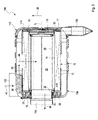
- FIG. 1 11 shows a perspective view of a filter system 100 according to an exemplary embodiment of the invention with a tangential inlet 102, centric outlet 104 on a housing front side and bottom-side dirt outlet 106.
- a round filter design is shown which consists of a housing 108 which is provided with a cover 110, for example with a screw cap. or bayonet lock, is closed.
- FIG. 2 shows a perspective view of a filter system 100 according to an embodiment with cover-side inlet 102 and centric outlet 104. Shown is also a round filter design, which consists of a housing 108 which is closed with a cover 110. The inlet, through which dust-laden air can enter the housing, is in this case arranged centrally above the internally mounted filter element. The outlet 104, through which the purified air can flow, is also as in FIG. 1 arranged centrally.
- Such filter systems as in FIGS. 1 and 2 are usually used in construction machinery and agricultural machinery. They are characterized by great robustness and have short life due to the high filter load. A filter system 100 with loaded filter element must tolerate a weight gain of 10 kg or more.
- FIG. 3 a longitudinal section through a filter system 100 according to an embodiment with tangential inlet 102, centric outlet 104 and bottom-side dirt outlet 106 is shown.
- the housing 108 of the filter system 100 is closed by a cover 110.
- a filter element 10, which consists of concentric with a longitudinal axis L arranged support tube 14 and filter body 12 is on two opposite end faces 15, 17 with a first and a second end plate 16, 18, which may be made of polyurethane foam or an elastomer, completed , Second end plate 18 and support tube 14 of the filter element 10 may also be made in one piece.
- the filter body 12 may, for example, be zigzag-folded, annularly closed and, for example, made of paper, made of paper reinforced with plastic fibers and / or made of plastic-coated paper.
- the second end plate 18, whose stability is increased by a reinforcing plate 30, has segmented discontinuous support nubs 20, which are arranged radially outwardly extending circularly about the longitudinal axis L and when installed in the female housing 108 on an inner cover contour 114 of the lid 110th adjacent lie in the radial direction 38 to the outside and thereby support on the housing 108 both axially and radially.
- a radial seal 26 is attached to the first end plate 16, whose stability is increased by a reinforcing ring 31, with the aid of which the filter element 10 is radially supported on the housing 108 via the sealing contour 116 and the unfiltered against seals the filtered air space.
- the filter element 10 is thus braced both axially and twice radially against the housing 108.
- Dust-laden air can flow in through the inlet 102 in the direction of the arrow 40, which in this case is shown as a tangential inlet and by means of which a cyclone separator 36 causes rotational movement of the air to enable cyclone operation.
- Dust particles can be deposited by the rotational movement partially pre-deposited on the inner housing wall and emptied by the Schmutzauslass 106 when installing the filter housing 108 in a horizontal position downwards by gravity from the filter system 100.
- the air flows during operation after partial separation of the dust particles through the filter body 12 in the direction of arrow 42, 44 into the interior 50 of the filter element. Dust particles, depending on the filter medium, are suspended in the filter medium above a certain size. Depending on the dust input, therefore, the filter element 10 must be replaced after a certain life.
- a secondary element 28 is mounted, which consists essentially of a supporting structure with a relatively permeable filter medium, for example a fleece, and when replacing the filter element 10 in the housing 108 for Protection of the further air duct, for example an internal combustion engine, against penetrating dust particles and other objects remains.
- the secondary element 28 is screwed with a screw 32 fixed to the outlet side of the housing 108.
- the filter element 10 can be used as a compact air filter, in particular as an air filter of an internal combustion engine. In principle, however, a use as a diesel particulate filter in a similar design is conceivable.
- FIG. 4 shows a filter element 10 according to the prior art with a closed reinforcing ring 31 and integrated end plates 16, 18.
- the filter element 10 is provided on both end faces 15 and 17 with the end plates 16 and 18, which terminate the filter element 10 at both end faces 15, 17 ,
- the right half of the filter element 10 is cut open, so that the filter body 12 and the support tube 14 can be seen.
- the reinforcing ring 31 can be seen, which is pulled around with a closed edge around the outer edge of the filter body 12.
- the end plate 16 is foamed to this end face 58 of the filter body 12 and seals it with the reinforcing ring 31 together.
- FIG. 5 is a perspective view of a filter body 12 to see a closed reinforcing ring 31 according to the prior art.
- the cylindrical filter body 12 is closed at the end face 58 with the reinforcing ring 31, which has a closed edge.
- a support tube 14 for stiffening the filter body 12 can be seen on the inside of the filter body 12.
- FIG. 6 shows a partial longitudinal section of a filter element 10 according to the prior art with a filter body 12 with closed reinforcing ring 31 and an integrated end plate 16, as shown in FIG FIG. 5 is shown. It can be seen on the filter body 12 and the reinforcing ring 31 foamed end plate 16. In the interior of the filter body 12, the filling level 54 of the mass of the end plate 16 can be seen, which is not observed from the outside due to the closed raised edge of the reinforcing ring 31 and thus neither during the manufacturing process still be controlled afterwards. The filling level can be determined only by cutting the reinforcing ring 31, that is a destructive control.
- FIG. 7 a filter element 10 according to an embodiment of the invention with a slotted reinforcing ring 31 and integrated end plates 16, 18 is shown.
- the filter element 10 is provided on both end faces 15 and 17 with the end plates 16 and 18, which terminate the filter element 10 at both end faces 15, 17.
- the right half of the filter element 10 is cut open, so that the filter body 12 and the support tube 14 can be seen.
- the reinforcing ring 31 can be seen, which is pulled around with a slotted edge around the outer edge of the filter body 12.
- the end plate 16 is foamed on end face 58 of the filter body 12 and seals it with the reinforcing ring 31 together.
- FIG. 8 shows a perspective view of a filter body 12 with a slotted reinforcing ring 31 according to an embodiment of the invention.
- the reinforcing ring 31 has slots 52a as externally visible openings 52.
- the inside of the reinforcing ring 31 adjoins the support tube 14.
- openings 52b which are visible from the inside can also be realized by other designs, that is to say not only by helical webs 56.
- FIG. 9 shows a partial longitudinal section of a filter element 10 according to an embodiment of the invention with a filter body 12, as in FIG. 8 shown, with a slotted reinforcing ring 31 and an integrated end plate 16 which is foamed to the end face 58 of the filter body 12.
- a representation is chosen in which a slot 52a is cut as an opening 52 straight, so that no wall of the reinforcing ring 31 can be seen on the outside of the filter element 10.
- the fill level 54 of the foam of the end plate 16 can be determined directly from the outside.
- a level control of a level of a mass for connecting the end plate 16 with the end face 58 of the filter body 12 via the determination of the rise height of a foam in the externally visible openings 52nd can also be done online directly during the manufacturing process of the end plate.
- the fill level of the foam can also be controlled on the inside of the filter body 12 via the internal openings 52b.
- the reinforcing ring 31 has in the embodiment of coiled webs 56 for better interlocking of the mass of the end plate 16 with the filter body 12 and thus permanent sealing of the end face 58 of the filter body 12.
Landscapes
- Physics & Mathematics (AREA)
- Geometry (AREA)
- Chemical & Material Sciences (AREA)
- Chemical Kinetics & Catalysis (AREA)
- Filtering Of Dispersed Particles In Gases (AREA)
Applications Claiming Priority (1)
| Application Number | Priority Date | Filing Date | Title |
|---|---|---|---|
| DE102013002276 | 2013-02-12 |
Publications (2)
| Publication Number | Publication Date |
|---|---|
| EP2764904A1 true EP2764904A1 (fr) | 2014-08-13 |
| EP2764904B1 EP2764904B1 (fr) | 2018-03-07 |
Family
ID=50028769
Family Applications (1)
| Application Number | Title | Priority Date | Filing Date |
|---|---|---|---|
| EP14151475.2A Active EP2764904B1 (fr) | 2013-02-12 | 2014-01-16 | Élément de filtre |
Country Status (3)
| Country | Link |
|---|---|
| EP (1) | EP2764904B1 (fr) |
| CN (1) | CN103982344B (fr) |
| DE (1) | DE102014000439A1 (fr) |
Cited By (6)
| Publication number | Priority date | Publication date | Assignee | Title |
|---|---|---|---|---|
| EP2851112A1 (fr) * | 2013-09-02 | 2015-03-25 | Mann + Hummel Gmbh | Élément de filtre et système de filtre équipé d'un élément de filtre |
| US10744444B2 (en) | 2016-05-03 | 2020-08-18 | Mann+Hummel Gmbh | Filter Element, in Particular for Gas Filtration, and filter device |
| US10773201B2 (en) | 2016-05-03 | 2020-09-15 | Mann+Hummel Gmbh | Annular filter element, in particular for gas filtration |
| US10881998B2 (en) | 2016-05-03 | 2021-01-05 | Mann+Hummel Gmbh | Filter device, in particular gas filter |
| US12403419B1 (en) | 2024-05-17 | 2025-09-02 | Donaldson Company, Inc. | Filter elements and assemblies |
| US12434181B1 (en) | 2024-11-01 | 2025-10-07 | Donaldson Company, Inc. | Air cleaner and filtration assemblies |
Families Citing this family (1)
| Publication number | Priority date | Publication date | Assignee | Title |
|---|---|---|---|---|
| DK3684493T3 (en) * | 2017-09-19 | 2023-01-23 | Cc Jensen As | Internal continuous air bypass |
Citations (5)
| Publication number | Priority date | Publication date | Assignee | Title |
|---|---|---|---|---|
| US20060254229A1 (en) * | 2005-05-03 | 2006-11-16 | Kevin Schrage | Air cleaner; air filter cartridge and method of manufacturing |
| DE102006036643A1 (de) * | 2006-08-03 | 2008-02-21 | Mann + Hummel Gmbh | Luftfilterelement mit transparenten Endscheiben und Herstellungsverfahren |
| WO2009047196A1 (fr) | 2007-10-02 | 2009-04-16 | Mann+Hummel Gmbh | Élément filtrant et système de filtre |
| WO2009146962A1 (fr) * | 2008-06-06 | 2009-12-10 | Mann+Hummel Gmbh | Système de filtre |
| DE102011106502A1 (de) * | 2011-06-15 | 2012-12-20 | Mann + Hummel Gmbh | Filterelement und Gehäuse für ein Filterelement |
Family Cites Families (1)
| Publication number | Priority date | Publication date | Assignee | Title |
|---|---|---|---|---|
| BRPI0514607B1 (pt) * | 2004-08-25 | 2019-10-01 | Donaldson Company, Inc. | Cartucho de filtro de ar adequado para instalação removível e conjunto de filtro de ar compreendendo o mesmo |
-
2014
- 2014-01-16 EP EP14151475.2A patent/EP2764904B1/fr active Active
- 2014-01-17 DE DE102014000439.2A patent/DE102014000439A1/de not_active Withdrawn
- 2014-02-12 CN CN201410048615.1A patent/CN103982344B/zh active Active
Patent Citations (5)
| Publication number | Priority date | Publication date | Assignee | Title |
|---|---|---|---|---|
| US20060254229A1 (en) * | 2005-05-03 | 2006-11-16 | Kevin Schrage | Air cleaner; air filter cartridge and method of manufacturing |
| DE102006036643A1 (de) * | 2006-08-03 | 2008-02-21 | Mann + Hummel Gmbh | Luftfilterelement mit transparenten Endscheiben und Herstellungsverfahren |
| WO2009047196A1 (fr) | 2007-10-02 | 2009-04-16 | Mann+Hummel Gmbh | Élément filtrant et système de filtre |
| WO2009146962A1 (fr) * | 2008-06-06 | 2009-12-10 | Mann+Hummel Gmbh | Système de filtre |
| DE102011106502A1 (de) * | 2011-06-15 | 2012-12-20 | Mann + Hummel Gmbh | Filterelement und Gehäuse für ein Filterelement |
Cited By (6)
| Publication number | Priority date | Publication date | Assignee | Title |
|---|---|---|---|---|
| EP2851112A1 (fr) * | 2013-09-02 | 2015-03-25 | Mann + Hummel Gmbh | Élément de filtre et système de filtre équipé d'un élément de filtre |
| US10744444B2 (en) | 2016-05-03 | 2020-08-18 | Mann+Hummel Gmbh | Filter Element, in Particular for Gas Filtration, and filter device |
| US10773201B2 (en) | 2016-05-03 | 2020-09-15 | Mann+Hummel Gmbh | Annular filter element, in particular for gas filtration |
| US10881998B2 (en) | 2016-05-03 | 2021-01-05 | Mann+Hummel Gmbh | Filter device, in particular gas filter |
| US12403419B1 (en) | 2024-05-17 | 2025-09-02 | Donaldson Company, Inc. | Filter elements and assemblies |
| US12434181B1 (en) | 2024-11-01 | 2025-10-07 | Donaldson Company, Inc. | Air cleaner and filtration assemblies |
Also Published As
| Publication number | Publication date |
|---|---|
| CN103982344B (zh) | 2018-02-16 |
| DE102014000439A1 (de) | 2014-08-14 |
| EP2764904B1 (fr) | 2018-03-07 |
| CN103982344A (zh) | 2014-08-13 |
Similar Documents
| Publication | Publication Date | Title |
|---|---|---|
| EP3470129B1 (fr) | Système de filtre à air et élément de filtre à air pour un système de filtre à air | |
| EP2813275B1 (fr) | Utilisation d'un élément de filtre dans un système de filtre | |
| EP2764904B1 (fr) | Élément de filtre | |
| EP2851110A1 (fr) | Élément de filtre et système de filtre équipé d'un élément de filtre | |
| DE102014000718B4 (de) | Filterelement | |
| EP3285909B1 (fr) | Élément secondaire pour système filtant ainsi que système filtrant doté d'un élément secondaire | |
| DE102014000927A1 (de) | Filterelement | |
| EP2862614B2 (fr) | Système de filtre équipé d'un élément de filtre | |
| EP2742986A1 (fr) | Système de filtre à air, élément de filtre à air et procédé de remplacement d'un élément de filtre à air | |
| EP2764905A1 (fr) | Corps de filtration | |
| EP2853305A1 (fr) | Élément de filtre et système de filtre équipé d'un élément de filtre | |
| DE102014012579B4 (de) | Filterelement, dessen Verwendung und Filtersystem | |
| DE102014012948A1 (de) | Filtersystem und Filterelement für ein Filtersystem | |
| DE102014012578B4 (de) | Filtersystem und dessen Verwendung | |
| DE102013014498B4 (de) | Filterelement, dessen Verwendung und Filtersystem | |
| DE102014001608A1 (de) | Luftfilterelement | |
| DE102014012947B4 (de) | Luftfiltersystem | |
| DE102014012944A1 (de) | Filtersystem mit Filterelement | |
| DE102014014319A1 (de) | Sekundärelement für ein Filtersystem | |
| DE202013011866U1 (de) | Filterelement und Filtersystem mit einem Filterelement | |
| DE102013014496A1 (de) | Filterelement | |
| DE102013014495A1 (de) | Filterelement |
Legal Events
| Date | Code | Title | Description |
|---|---|---|---|
| PUAI | Public reference made under article 153(3) epc to a published international application that has entered the european phase |
Free format text: ORIGINAL CODE: 0009012 |
|
| 17P | Request for examination filed |
Effective date: 20140116 |
|
| AK | Designated contracting states |
Kind code of ref document: A1 Designated state(s): AL AT BE BG CH CY CZ DE DK EE ES FI FR GB GR HR HU IE IS IT LI LT LU LV MC MK MT NL NO PL PT RO RS SE SI SK SM TR |
|
| AX | Request for extension of the european patent |
Extension state: BA ME |
|
| R17P | Request for examination filed (corrected) |
Effective date: 20141202 |
|
| RBV | Designated contracting states (corrected) |
Designated state(s): AL AT BE BG CH CY CZ DE DK EE ES FI FR GB GR HR HU IE IS IT LI LT LU LV MC MK MT NL NO PL PT RO RS SE SI SK SM TR |
|
| 17Q | First examination report despatched |
Effective date: 20160502 |
|
| STAA | Information on the status of an ep patent application or granted ep patent |
Free format text: STATUS: EXAMINATION IS IN PROGRESS |
|
| GRAP | Despatch of communication of intention to grant a patent |
Free format text: ORIGINAL CODE: EPIDOSNIGR1 |
|
| STAA | Information on the status of an ep patent application or granted ep patent |
Free format text: STATUS: GRANT OF PATENT IS INTENDED |
|
| INTG | Intention to grant announced |
Effective date: 20170811 |
|
| GRAS | Grant fee paid |
Free format text: ORIGINAL CODE: EPIDOSNIGR3 |
|
| RAP1 | Party data changed (applicant data changed or rights of an application transferred) |
Owner name: MANN+HUMMEL GMBH |
|
| GRAA | (expected) grant |
Free format text: ORIGINAL CODE: 0009210 |
|
| STAA | Information on the status of an ep patent application or granted ep patent |
Free format text: STATUS: THE PATENT HAS BEEN GRANTED |
|
| AK | Designated contracting states |
Kind code of ref document: B1 Designated state(s): AL AT BE BG CH CY CZ DE DK EE ES FI FR GB GR HR HU IE IS IT LI LT LU LV MC MK MT NL NO PL PT RO RS SE SI SK SM TR |
|
| REG | Reference to a national code |
Ref country code: GB Ref legal event code: FG4D Free format text: NOT ENGLISH |
|
| REG | Reference to a national code |
Ref country code: CH Ref legal event code: EP Ref country code: AT Ref legal event code: REF Ref document number: 975939 Country of ref document: AT Kind code of ref document: T Effective date: 20180315 |
|
| REG | Reference to a national code |
Ref country code: IE Ref legal event code: FG4D Free format text: LANGUAGE OF EP DOCUMENT: GERMAN |
|
| REG | Reference to a national code |
Ref country code: DE Ref legal event code: R096 Ref document number: 502014007494 Country of ref document: DE |
|
| REG | Reference to a national code |
Ref country code: NL Ref legal event code: MP Effective date: 20180307 |
|
| REG | Reference to a national code |
Ref country code: DE Ref legal event code: R081 Ref document number: 502014007494 Country of ref document: DE Owner name: MANN+HUMMEL GMBH, DE Free format text: FORMER OWNER: MANN + HUMMEL GMBH, 71638 LUDWIGSBURG, DE |
|
| REG | Reference to a national code |
Ref country code: LT Ref legal event code: MG4D |
|
| PG25 | Lapsed in a contracting state [announced via postgrant information from national office to epo] |
Ref country code: ES Free format text: LAPSE BECAUSE OF FAILURE TO SUBMIT A TRANSLATION OF THE DESCRIPTION OR TO PAY THE FEE WITHIN THE PRESCRIBED TIME-LIMIT Effective date: 20180307 Ref country code: NO Free format text: LAPSE BECAUSE OF FAILURE TO SUBMIT A TRANSLATION OF THE DESCRIPTION OR TO PAY THE FEE WITHIN THE PRESCRIBED TIME-LIMIT Effective date: 20180607 Ref country code: FI Free format text: LAPSE BECAUSE OF FAILURE TO SUBMIT A TRANSLATION OF THE DESCRIPTION OR TO PAY THE FEE WITHIN THE PRESCRIBED TIME-LIMIT Effective date: 20180307 Ref country code: LT Free format text: LAPSE BECAUSE OF FAILURE TO SUBMIT A TRANSLATION OF THE DESCRIPTION OR TO PAY THE FEE WITHIN THE PRESCRIBED TIME-LIMIT Effective date: 20180307 Ref country code: CY Free format text: LAPSE BECAUSE OF FAILURE TO SUBMIT A TRANSLATION OF THE DESCRIPTION OR TO PAY THE FEE WITHIN THE PRESCRIBED TIME-LIMIT Effective date: 20180307 Ref country code: HR Free format text: LAPSE BECAUSE OF FAILURE TO SUBMIT A TRANSLATION OF THE DESCRIPTION OR TO PAY THE FEE WITHIN THE PRESCRIBED TIME-LIMIT Effective date: 20180307 |
|
| PG25 | Lapsed in a contracting state [announced via postgrant information from national office to epo] |
Ref country code: BG Free format text: LAPSE BECAUSE OF FAILURE TO SUBMIT A TRANSLATION OF THE DESCRIPTION OR TO PAY THE FEE WITHIN THE PRESCRIBED TIME-LIMIT Effective date: 20180607 Ref country code: RS Free format text: LAPSE BECAUSE OF FAILURE TO SUBMIT A TRANSLATION OF THE DESCRIPTION OR TO PAY THE FEE WITHIN THE PRESCRIBED TIME-LIMIT Effective date: 20180307 Ref country code: SE Free format text: LAPSE BECAUSE OF FAILURE TO SUBMIT A TRANSLATION OF THE DESCRIPTION OR TO PAY THE FEE WITHIN THE PRESCRIBED TIME-LIMIT Effective date: 20180307 Ref country code: LV Free format text: LAPSE BECAUSE OF FAILURE TO SUBMIT A TRANSLATION OF THE DESCRIPTION OR TO PAY THE FEE WITHIN THE PRESCRIBED TIME-LIMIT Effective date: 20180307 Ref country code: GR Free format text: LAPSE BECAUSE OF FAILURE TO SUBMIT A TRANSLATION OF THE DESCRIPTION OR TO PAY THE FEE WITHIN THE PRESCRIBED TIME-LIMIT Effective date: 20180608 |
|
| PG25 | Lapsed in a contracting state [announced via postgrant information from national office to epo] |
Ref country code: MT Free format text: LAPSE BECAUSE OF FAILURE TO SUBMIT A TRANSLATION OF THE DESCRIPTION OR TO PAY THE FEE WITHIN THE PRESCRIBED TIME-LIMIT Effective date: 20180307 |
|
| PG25 | Lapsed in a contracting state [announced via postgrant information from national office to epo] |
Ref country code: EE Free format text: LAPSE BECAUSE OF FAILURE TO SUBMIT A TRANSLATION OF THE DESCRIPTION OR TO PAY THE FEE WITHIN THE PRESCRIBED TIME-LIMIT Effective date: 20180307 Ref country code: NL Free format text: LAPSE BECAUSE OF FAILURE TO SUBMIT A TRANSLATION OF THE DESCRIPTION OR TO PAY THE FEE WITHIN THE PRESCRIBED TIME-LIMIT Effective date: 20180307 Ref country code: RO Free format text: LAPSE BECAUSE OF FAILURE TO SUBMIT A TRANSLATION OF THE DESCRIPTION OR TO PAY THE FEE WITHIN THE PRESCRIBED TIME-LIMIT Effective date: 20180307 Ref country code: PL Free format text: LAPSE BECAUSE OF FAILURE TO SUBMIT A TRANSLATION OF THE DESCRIPTION OR TO PAY THE FEE WITHIN THE PRESCRIBED TIME-LIMIT Effective date: 20180307 Ref country code: AL Free format text: LAPSE BECAUSE OF FAILURE TO SUBMIT A TRANSLATION OF THE DESCRIPTION OR TO PAY THE FEE WITHIN THE PRESCRIBED TIME-LIMIT Effective date: 20180307 |
|
| PG25 | Lapsed in a contracting state [announced via postgrant information from national office to epo] |
Ref country code: SM Free format text: LAPSE BECAUSE OF FAILURE TO SUBMIT A TRANSLATION OF THE DESCRIPTION OR TO PAY THE FEE WITHIN THE PRESCRIBED TIME-LIMIT Effective date: 20180307 Ref country code: SK Free format text: LAPSE BECAUSE OF FAILURE TO SUBMIT A TRANSLATION OF THE DESCRIPTION OR TO PAY THE FEE WITHIN THE PRESCRIBED TIME-LIMIT Effective date: 20180307 Ref country code: CZ Free format text: LAPSE BECAUSE OF FAILURE TO SUBMIT A TRANSLATION OF THE DESCRIPTION OR TO PAY THE FEE WITHIN THE PRESCRIBED TIME-LIMIT Effective date: 20180307 |
|
| REG | Reference to a national code |
Ref country code: DE Ref legal event code: R097 Ref document number: 502014007494 Country of ref document: DE |
|
| PG25 | Lapsed in a contracting state [announced via postgrant information from national office to epo] |
Ref country code: PT Free format text: LAPSE BECAUSE OF FAILURE TO SUBMIT A TRANSLATION OF THE DESCRIPTION OR TO PAY THE FEE WITHIN THE PRESCRIBED TIME-LIMIT Effective date: 20180709 |
|
| PLBE | No opposition filed within time limit |
Free format text: ORIGINAL CODE: 0009261 |
|
| STAA | Information on the status of an ep patent application or granted ep patent |
Free format text: STATUS: NO OPPOSITION FILED WITHIN TIME LIMIT |
|
| PG25 | Lapsed in a contracting state [announced via postgrant information from national office to epo] |
Ref country code: DK Free format text: LAPSE BECAUSE OF FAILURE TO SUBMIT A TRANSLATION OF THE DESCRIPTION OR TO PAY THE FEE WITHIN THE PRESCRIBED TIME-LIMIT Effective date: 20180307 |
|
| 26N | No opposition filed |
Effective date: 20181210 |
|
| PG25 | Lapsed in a contracting state [announced via postgrant information from national office to epo] |
Ref country code: SI Free format text: LAPSE BECAUSE OF FAILURE TO SUBMIT A TRANSLATION OF THE DESCRIPTION OR TO PAY THE FEE WITHIN THE PRESCRIBED TIME-LIMIT Effective date: 20180307 Ref country code: IT Free format text: LAPSE BECAUSE OF FAILURE TO SUBMIT A TRANSLATION OF THE DESCRIPTION OR TO PAY THE FEE WITHIN THE PRESCRIBED TIME-LIMIT Effective date: 20180307 |
|
| PG25 | Lapsed in a contracting state [announced via postgrant information from national office to epo] |
Ref country code: MC Free format text: LAPSE BECAUSE OF FAILURE TO SUBMIT A TRANSLATION OF THE DESCRIPTION OR TO PAY THE FEE WITHIN THE PRESCRIBED TIME-LIMIT Effective date: 20180307 |
|
| REG | Reference to a national code |
Ref country code: CH Ref legal event code: PL |
|
| GBPC | Gb: european patent ceased through non-payment of renewal fee |
Effective date: 20190116 |
|
| PG25 | Lapsed in a contracting state [announced via postgrant information from national office to epo] |
Ref country code: LU Free format text: LAPSE BECAUSE OF NON-PAYMENT OF DUE FEES Effective date: 20190116 |
|
| REG | Reference to a national code |
Ref country code: BE Ref legal event code: MM Effective date: 20190131 |
|
| REG | Reference to a national code |
Ref country code: IE Ref legal event code: MM4A |
|
| PG25 | Lapsed in a contracting state [announced via postgrant information from national office to epo] |
Ref country code: BE Free format text: LAPSE BECAUSE OF NON-PAYMENT OF DUE FEES Effective date: 20190131 |
|
| PG25 | Lapsed in a contracting state [announced via postgrant information from national office to epo] |
Ref country code: GB Free format text: LAPSE BECAUSE OF NON-PAYMENT OF DUE FEES Effective date: 20190116 Ref country code: CH Free format text: LAPSE BECAUSE OF NON-PAYMENT OF DUE FEES Effective date: 20190131 Ref country code: LI Free format text: LAPSE BECAUSE OF NON-PAYMENT OF DUE FEES Effective date: 20190131 |
|
| PG25 | Lapsed in a contracting state [announced via postgrant information from national office to epo] |
Ref country code: IE Free format text: LAPSE BECAUSE OF NON-PAYMENT OF DUE FEES Effective date: 20190116 |
|
| REG | Reference to a national code |
Ref country code: AT Ref legal event code: MM01 Ref document number: 975939 Country of ref document: AT Kind code of ref document: T Effective date: 20190116 |
|
| PG25 | Lapsed in a contracting state [announced via postgrant information from national office to epo] |
Ref country code: AT Free format text: LAPSE BECAUSE OF NON-PAYMENT OF DUE FEES Effective date: 20190116 |
|
| PG25 | Lapsed in a contracting state [announced via postgrant information from national office to epo] |
Ref country code: IS Free format text: LAPSE BECAUSE OF FAILURE TO SUBMIT A TRANSLATION OF THE DESCRIPTION OR TO PAY THE FEE WITHIN THE PRESCRIBED TIME-LIMIT Effective date: 20180707 |
|
| PG25 | Lapsed in a contracting state [announced via postgrant information from national office to epo] |
Ref country code: HU Free format text: LAPSE BECAUSE OF FAILURE TO SUBMIT A TRANSLATION OF THE DESCRIPTION OR TO PAY THE FEE WITHIN THE PRESCRIBED TIME-LIMIT; INVALID AB INITIO Effective date: 20140116 |
|
| PG25 | Lapsed in a contracting state [announced via postgrant information from national office to epo] |
Ref country code: MK Free format text: LAPSE BECAUSE OF FAILURE TO SUBMIT A TRANSLATION OF THE DESCRIPTION OR TO PAY THE FEE WITHIN THE PRESCRIBED TIME-LIMIT Effective date: 20180307 |
|
| P01 | Opt-out of the competence of the unified patent court (upc) registered |
Effective date: 20230731 |
|
| PGFP | Annual fee paid to national office [announced via postgrant information from national office to epo] |
Ref country code: DE Payment date: 20260121 Year of fee payment: 13 |
|
| PGFP | Annual fee paid to national office [announced via postgrant information from national office to epo] |
Ref country code: FR Payment date: 20260123 Year of fee payment: 13 |
|
| PGFP | Annual fee paid to national office [announced via postgrant information from national office to epo] |
Ref country code: TR Payment date: 20260115 Year of fee payment: 13 |