EP2764954A1 - Outil d'usinage - Google Patents
Outil d'usinage Download PDFInfo
- Publication number
- EP2764954A1 EP2764954A1 EP13154165.8A EP13154165A EP2764954A1 EP 2764954 A1 EP2764954 A1 EP 2764954A1 EP 13154165 A EP13154165 A EP 13154165A EP 2764954 A1 EP2764954 A1 EP 2764954A1
- Authority
- EP
- European Patent Office
- Prior art keywords
- power transmission
- roller
- machining
- contact
- belt
- Prior art date
- Legal status (The legal status is an assumption and is not a legal conclusion. Google has not performed a legal analysis and makes no representation as to the accuracy of the status listed.)
- Granted
Links
Images


Classifications
-
- B—PERFORMING OPERATIONS; TRANSPORTING
- B24—GRINDING; POLISHING
- B24B—MACHINES, DEVICES, OR PROCESSES FOR GRINDING OR POLISHING; DRESSING OR CONDITIONING OF ABRADING SURFACES; FEEDING OF GRINDING, POLISHING, OR LAPPING AGENTS
- B24B21/00—Machines or devices using grinding or polishing belts; Accessories therefor
- B24B21/18—Accessories
- B24B21/20—Accessories for controlling or adjusting the tracking or the tension of the grinding belt
-
- B—PERFORMING OPERATIONS; TRANSPORTING
- B24—GRINDING; POLISHING
- B24B—MACHINES, DEVICES, OR PROCESSES FOR GRINDING OR POLISHING; DRESSING OR CONDITIONING OF ABRADING SURFACES; FEEDING OF GRINDING, POLISHING, OR LAPPING AGENTS
- B24B21/00—Machines or devices using grinding or polishing belts; Accessories therefor
- B24B21/04—Machines or devices using grinding or polishing belts; Accessories therefor for grinding plane surfaces
- B24B21/12—Machines or devices using grinding or polishing belts; Accessories therefor for grinding plane surfaces involving a contact wheel or roller pressing the belt against the work
- B24B21/14—Contact wheels; Contact rollers; Belt supporting rolls
-
- B—PERFORMING OPERATIONS; TRANSPORTING
- B24—GRINDING; POLISHING
- B24B—MACHINES, DEVICES, OR PROCESSES FOR GRINDING OR POLISHING; DRESSING OR CONDITIONING OF ABRADING SURFACES; FEEDING OF GRINDING, POLISHING, OR LAPPING AGENTS
- B24B23/00—Portable grinding machines, e.g. hand-guided; Accessories therefor
- B24B23/06—Portable grinding machines, e.g. hand-guided; Accessories therefor with abrasive belts, e.g. with endless travelling belts; Accessories therefor
-
- B—PERFORMING OPERATIONS; TRANSPORTING
- B24—GRINDING; POLISHING
- B24B—MACHINES, DEVICES, OR PROCESSES FOR GRINDING OR POLISHING; DRESSING OR CONDITIONING OF ABRADING SURFACES; FEEDING OF GRINDING, POLISHING, OR LAPPING AGENTS
- B24B27/00—Other grinding machines or devices
- B24B27/0038—Other grinding machines or devices with the grinding tool mounted at the end of a set of bars
-
- B—PERFORMING OPERATIONS; TRANSPORTING
- B24—GRINDING; POLISHING
- B24B—MACHINES, DEVICES, OR PROCESSES FOR GRINDING OR POLISHING; DRESSING OR CONDITIONING OF ABRADING SURFACES; FEEDING OF GRINDING, POLISHING, OR LAPPING AGENTS
- B24B41/00—Component parts such as frames, beds, carriages, headstocks
- B24B41/002—Grinding heads
-
- B—PERFORMING OPERATIONS; TRANSPORTING
- B24—GRINDING; POLISHING
- B24B—MACHINES, DEVICES, OR PROCESSES FOR GRINDING OR POLISHING; DRESSING OR CONDITIONING OF ABRADING SURFACES; FEEDING OF GRINDING, POLISHING, OR LAPPING AGENTS
- B24B45/00—Means for securing grinding wheels on rotary arbors
-
- B—PERFORMING OPERATIONS; TRANSPORTING
- B24—GRINDING; POLISHING
- B24B—MACHINES, DEVICES, OR PROCESSES FOR GRINDING OR POLISHING; DRESSING OR CONDITIONING OF ABRADING SURFACES; FEEDING OF GRINDING, POLISHING, OR LAPPING AGENTS
- B24B47/00—Drives or gearings; Equipment therefor
- B24B47/10—Drives or gearings; Equipment therefor for rotating or reciprocating working-spindles carrying grinding wheels or workpieces
- B24B47/12—Drives or gearings; Equipment therefor for rotating or reciprocating working-spindles carrying grinding wheels or workpieces by mechanical gearing or electric power
-
- B—PERFORMING OPERATIONS; TRANSPORTING
- B25—HAND TOOLS; PORTABLE POWER-DRIVEN TOOLS; MANIPULATORS
- B25J—MANIPULATORS; CHAMBERS PROVIDED WITH MANIPULATION DEVICES
- B25J11/00—Manipulators not otherwise provided for
- B25J11/005—Manipulators for mechanical processing tasks
- B25J11/006—Deburring or trimming
-
- B—PERFORMING OPERATIONS; TRANSPORTING
- B25—HAND TOOLS; PORTABLE POWER-DRIVEN TOOLS; MANIPULATORS
- B25J—MANIPULATORS; CHAMBERS PROVIDED WITH MANIPULATION DEVICES
- B25J11/00—Manipulators not otherwise provided for
- B25J11/005—Manipulators for mechanical processing tasks
- B25J11/0065—Polishing or grinding
Definitions
- the invention relates to a machining tool.
- a machining tool such as a belt grinder which is repeatedly connectable to and releasable from a robotic arm has a grinding belt rotating over rollers.
- One of the rollers is at a tip of a contact arm for bringing the grinding belt in contact with the surface of a machined object.
- Another roller is a power transmission roller which provides kinetic energy with the grinding belt when it is rotating.
- the machining tool has also a motor for rotating the power transmission roller.
- the motor is typically an electric motor or an air motor.
- Such a robotic machining tool arrangement has problems. For example, opening a mechanical coupling between the machining tool and the robotic arm is not enough for separating the machining tool from the robotic arm but the electric wires or pressure hoses must also be separately released. Correspondingly, after a mechanical coupling between the machining tool and the robotic arm a separate electrical or pneumatic coupling must be made manually which is frustrating and complicated.
- the grinding belt must be properly tensioned when it is used for grinding. Similar to coupling and decoupling of the machining tool, the tensioning is also manual work.
- the grinding belt is tightened by extending the contact arm between the rollers.
- a grinding belt may need tightening several times during use which is impractical and bothersome.
- the change in length of the contact arm also changes the location of the grinding contact to the object from the machining tool point of view. That makes it difficult or impossible for the robot to automatically aim the machining tool to a desired place on the machined object which may lower or spoil the quality of the end product.
- An aspect of the invention relates to a claim 1.
- the present solution provides advantages.
- the new features in coupling of both the machine tool as such and the machining belt become easier and reduce manual work.
- the machining belt needs no repetitive tensioning.
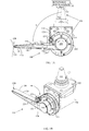
- Figure 1A presents a machining tool 100 directly from a side and Figure 1B presents the machining tool 100 from an oblique direction.
- the machining tool 100 comprises a power transmission mechanism 102, a circular machining belt 104, a tightening mechanism 106 and a contact mechanism 108.
- the contact mechanism 108 is used for a tool contact with an object 110 to be machined.
- the machining belt 104 is a loop belt without a beginning and an end.
- a loop has a shape of a round or oval ring and it may be formed from a band of material by turning opposite ends of the band towards each other and fastening the ends together, for example.
- the machining tool 100 may be meant for shaping and/or finishing the object 110, for example.
- the machining tool 100 may be a belt grinder or the like to be used in a robotic arm.
- the machining belt 104 may be an abrasive belt, a sanding belt, a grinding belt, a deburring belt, a blending belt, a finishing belt, a polishing belt or the like for removing material from the surface of an object 110.
- a width of the machining belt 104 may be 1 mm to 50 mm, for example.
- a length of the machining belt 104 may be 10 mm to 1000 mm (depending on contact arm), for example.
- the power transmission mechanism 102 of the machining tool 100 can be mechanically coupled with a rotational power source 112 which may be realized on the basis of a connection part 132.
- An arrow shows an example of the rotation direction of the connection part 132 which corresponds to that of the rotational power source 112. The direction of rotation may also be altered.
- the connection part 132 has a shape and structure which fits with the connecting part of the rotational power source 112.
- the rotational power source 112 may comprise an electric motor or an air motor, for example.
- the power transmission mechanism 102 may turn the direction of the rotation axis by a desired amount inside the machining tool 100. The turn of the direction of the rotation axis may be 90°, for example.
- the contact mechanism 108 and the power transmission mechanism 102 have a structural design capable of receiving and holding the circular machining belt 104 for performing machining with the machining tool 100.
- the circular machining belt 104 is thus looped between the contact mechanism 108 and the power transmission mechanism 102.
- the contact mechanism 108 and the power transmission mechanism 102 have a desired distance shorter than about a half of the length of the circular machining belt 104 therebetween in order to enable the use of the circular machining belt 104 for machining.
- the contact roller shaft 124 and the power transmission shaft 202 may have a contact arm 220 of a desired length therebetween for realizing the distance of about a half of the circumference of the machining belt 104.
- the circular machining belt 104 may circulate between the contact mechanism 110 and the power transmission mechanism 102 in response to the rotation of the power transmission mechanism 102. In that way, the object 110 may be machined with the moving machining belt 104.
- the circular machining belt 104 may be looped over a contact roller 126 at the tip of the contact arm 220 and a power transmission roller 200 for causing the circular machining belt 104 to move over the contact roller 126 and power transmission roller 200 in response to the rotation of the power transmission shaft 202.
- the transmission roller 200 supplies kinetic energy to the machining belt 104.
- the contact roller 126 rolls with the machining belt 104 with low friction.
- the length of the contact arm 220 should be a little too short for mounting the machining belt 104 and thus the machining belt 104 may remain slightly loose without separate tensioning.
- the tightening may be performed by the tightening mechanism 106 which may press sections 120, 122 of the circular machining belt 104 between the contact mechanism 108 and power transmission mechanism 102 towards each other.
- the fact that the length of the contact arm 220 does not need to be changed for tightening enables working with good accuracy and without breaks.
- the tightening mechanism 106 may comprise at least one spring structure 210 and at least one spring roller 130.
- One end of the spring structure 210 may be coupled with the spring roller 130 and the other end may be fixed to an immobile part of the machining tool 100.
- the fixing point of the other end of the spring structure 210 may be near the power transmission mechanism 102 and the transmission shaft 200.
- the spring structure 210 may comprise or be similar to a leaf spring or a wire spring, for example.
- the spring structure 210 may comprise a coil spring, too.
- the curve or the coil of the spring structure 210 may twist partly of fully around the transmission shaft 200.
- the tightening mechanism 106 may be released for changing the machining belt 104.
- the tightening mechanism 106 may be easily released.
- the tightening mechanism 106 may be released by loosening a screw 280 attaching the spring roller 130. Also the screw 276 may be released.
- the tightening mechanism 106 may have a spring shaft 128, and the spring roller 130 may be coupled with the spring shaft 128 of the tightening mechanism 106 for enabling rotation of the spring roller 130 round the spring shaft 128 with the speed of the machining belt 104 during pressing against the machining belt 104. Between the spring shaft 128 and the spring roller 130 there may be a bearing.
- the spring structure 210 causes a spring force towards the machining belt 104 and that is why the spring roller 130 presses against the machining belt 104 with the spring force which results in a proper tensioning of the machining belt 104.
- the tightening mechanism 106 may have a single spring roller 130 which presses against one section 120 or 122 of the circular machining belt 104 between the contact roller 126 and power transmission roller 200 towards another.
- one section 120 (alternatively 122) moves towards second section 122 (alternatively 120) because of the pressure while the second section 122 (alternatively 120) is static in that respect.
- the machining belt 104 may be rotating round the contact mechanism 108 and the power transmission mechanism 102.
- the tightening mechanism 106 may comprise more than one spring roller 130, 270 which may press both circular machining belt sections 120, 122 facing one another between the contact roller 126 and power transmission roller 200 towards each other.
- the tightening mechanism 106 may have a spring roller 270, a shaft 272, a spring structure 274 and a fixing screw 278 of its own.
- the distance between the contact mechanism 108 and the power transmission mechanism 102 does not need to be changed. That is an advantage for a robotic machining, for example, because any change in the location of the contact mechanism 108 which is the machining head causes problems in controlling the machining process. With tensioning mechanism 106 the location of the contact surface for machining the object 110 can be kept static. All in all, because the belt stretch take-up is eliminated by the tightening mechanism 106 instead of an adjustment of the contact arm 220, the result is a precise and unchanged front contact roller 126 position which results in better controllability and end result.
- the spring roller 130 may have a rotational axis at least approximately parallel to the contact roller 126 and the power transmission roller 200. With the parallel rotational axes the use of the machining belt 104 is easy.
- the contact mechanism 108 may comprise a contact roller shaft 124 and a contact roller 126 such that the contact roller 126 rolls round the contact roller shaft 124.
- the movement of the machining belt 104 causes the contact roller 126 to roll.
- Figure 3 presents a direct side view of the machining tool 100 from a different angle of view with respect to Figure 1A .
- the power transmission mechanism 102 may comprise a power transmission roller 200 and a power transmission shaft 202.
- the power transmission roller 200 is connected with the power transmission shaft 202 for enabling rotation of the power transmission roller 200 with the power transmission shaft 202.
- the power transmission shaft 202 has a mechanical connection 320 with the connecting part 132 for rotating the power transmission shaft 202.
- the mechanical connection 320 between the transmission shaft 202 and the connecting part 132 may be realized with a gear.
- the gear may comprise toothed wheels at least two of them being engaged with one another.
- the gear may be used for changing or varying the rotational velocity between the toothed wheels and thus also between the connecting part 132 and the transmission shaft 202.
- the change in velocity finally has effect also on the velocity of the transmission roller 200 and the machining belt 104.
- the direction of the rotation may be changed.
- An example of the gear is a bevel gear or the like, which turns the rotational axis by 90°.
- the transmission roller 200 may rotate 1 rpm to 15000 rpm, for example.
- a possible rotation for the connecting part 132 and the transmission roller 200 may be 3000 rpm.
- the gear ratio may be 1:1, for example, but the ratio may also be different.
- the machining belt 104 may then move 1 m/min to 2000 m/min, for example.
- the connecting part 132 may have a connection with the rotational power source 112 using a spindle connection.
- the spindle connection may be based on an industrial standard tool taper interface such as HSK63-F or ISO30.
- the spindle connection may also be called a gear connection.
- the spindle connection may be used also during storage of the machine tool 100.
- the machining tool 100 may be repeatedly and releasably connectable with the rotational power source 112 such that the connecting part 132 is mechanically connected to and released from a counterpart of the rotational power source 112.
- the spindle connection is suitable for repeatable connection and disconnection. With the mechanical connection such as spindle connection there is no need to connect and disconnect electrical wires or air pipes to the machining tool 100.
- the machining tool 100 may comprise a casing 250 which may also be a supporting structure.
- One end of the spring structure 210, 274 may directly or indirectly be fixed to the casing 250 for applying the spring force to the machining belt 104 in order to tighten it.
- the fixing to the casing 250 may be performed by a screw 276 or the like, for example.
- the machining tool 100 may have a set of contact arm pieces 400, 402.
- One contact arm piece 400, 402 may be selected for use between the contact roller shaft 126 and the power transmission shaft 200.
- the length of the contact arm 220 with each contact arm piece 400, 402 may be set when a tightening screw 404 is loosened. After a proper length is set the screw 404 may be tightened such that the length remains unchanged.
- the contact arms 400, 402 may include straight arms, angled arms, shoe-shine style arms, for example.
- FIG. 2 shows the direction of the arm 220, 400 may be turned in an embodiment.
- the arm which is turned by 180° with respect to the rotational axis 350 of the connecting part 132 is shown with a dashed line.
- the arm 220, 400 may be turned from an angle ⁇ of 90° to an angle of 180° or even to an angle of -90°, for example.
- the turning may be performed continuously or discretely.
- the discrete turning may be performed with 15° steps, for example.
Landscapes
- Engineering & Computer Science (AREA)
- Mechanical Engineering (AREA)
- Robotics (AREA)
- Finish Polishing, Edge Sharpening, And Grinding By Specific Grinding Devices (AREA)
Priority Applications (4)
| Application Number | Priority Date | Filing Date | Title |
|---|---|---|---|
| EP13154165.8A EP2764954B1 (fr) | 2013-02-06 | 2013-02-06 | Outil d'usinage |
| ES13154165.8T ES2588002T3 (es) | 2013-02-06 | 2013-02-06 | Máquina herramienta |
| US14/172,487 US9156120B2 (en) | 2013-02-06 | 2014-02-04 | Machining tool |
| SG2014008429A SG2014008429A (en) | 2013-02-06 | 2014-02-05 | Machining tool |
Applications Claiming Priority (1)
| Application Number | Priority Date | Filing Date | Title |
|---|---|---|---|
| EP13154165.8A EP2764954B1 (fr) | 2013-02-06 | 2013-02-06 | Outil d'usinage |
Publications (2)
| Publication Number | Publication Date |
|---|---|
| EP2764954A1 true EP2764954A1 (fr) | 2014-08-13 |
| EP2764954B1 EP2764954B1 (fr) | 2016-05-25 |
Family
ID=47715887
Family Applications (1)
| Application Number | Title | Priority Date | Filing Date |
|---|---|---|---|
| EP13154165.8A Not-in-force EP2764954B1 (fr) | 2013-02-06 | 2013-02-06 | Outil d'usinage |
Country Status (4)
| Country | Link |
|---|---|
| US (1) | US9156120B2 (fr) |
| EP (1) | EP2764954B1 (fr) |
| ES (1) | ES2588002T3 (fr) |
| SG (1) | SG2014008429A (fr) |
Cited By (3)
| Publication number | Priority date | Publication date | Assignee | Title |
|---|---|---|---|---|
| CN104959893A (zh) * | 2015-07-28 | 2015-10-07 | 安徽潜山轴承制造有限公司 | 一种稳定可靠的轴承抛光机 |
| CN110948345A (zh) * | 2019-11-26 | 2020-04-03 | 福尼斯智能装备(珠海)有限公司 | 一种力控砂带打磨机 |
| CN111496636A (zh) * | 2020-04-21 | 2020-08-07 | 旌德县青川玻纤有限公司 | 一种智能调节的玻璃纤维板双面打磨设备 |
Families Citing this family (9)
| Publication number | Priority date | Publication date | Assignee | Title |
|---|---|---|---|---|
| US10137554B2 (en) * | 2016-08-23 | 2018-11-27 | Techway Industrial Co., Ltd. | Hand-held belt sander |
| US10427270B2 (en) * | 2016-10-01 | 2019-10-01 | Ingersoll-Rand Company | Belt sander ergonomic articulating arm belt with button release, lock, and sealed housing |
| CN107953207A (zh) * | 2017-12-26 | 2018-04-24 | 佛山市艾乐博机器人科技有限公司 | 一种打磨设备及其加工方法 |
| CN110370120A (zh) * | 2019-07-16 | 2019-10-25 | 陈新益 | 一种用于汽车配件加工的打磨装置 |
| GB2597699B (en) * | 2020-07-30 | 2022-10-12 | Saab Seaeye Ltd | Tool attachment, tool changer and corresponding method of use |
| US12194586B2 (en) * | 2022-01-07 | 2025-01-14 | Dc Precision Ceramics, Llc | Sanding systems, methods, and devices |
| FI131280B1 (en) * | 2022-10-07 | 2025-01-27 | Mirka Ltd | Compact belt sander |
| JP2024121860A (ja) * | 2023-02-28 | 2024-09-09 | Uht株式会社 | 駆動工具 |
| CN117020867A (zh) * | 2023-09-05 | 2023-11-10 | 中国科学院光电技术研究所 | 一种轮带式抛光装置 |
Citations (2)
| Publication number | Priority date | Publication date | Assignee | Title |
|---|---|---|---|---|
| EP1990133A2 (fr) * | 2007-05-11 | 2008-11-12 | Jürgen Heesemann | Agrégat de ponçage comme outil pour un dispositif de traitement |
| DE102011104010A1 (de) * | 2011-06-10 | 2012-12-13 | Gerd Eisenblätter Gmbh | Bandschleifvorrichtung |
Family Cites Families (21)
| Publication number | Priority date | Publication date | Assignee | Title |
|---|---|---|---|---|
| DE1652197A1 (de) * | 1967-07-08 | 1971-11-25 | Schmid & Wezel | Bandschleifgeraet |
| US3643385A (en) * | 1967-09-30 | 1972-02-22 | Toshio Mikiya | Portable grinding tool |
| CH482507A (de) * | 1967-10-05 | 1969-12-15 | Schmid & Wezel | Bandschleifgerät |
| US3983664A (en) * | 1975-11-21 | 1976-10-05 | Ronald Martin | Belt-type sander attachment for portable power drills |
| US4368597A (en) * | 1980-08-28 | 1983-01-18 | Dynabrade, Inc. | Miniature belt grinder |
| US4347689A (en) * | 1980-10-20 | 1982-09-07 | Verbatim Corporation | Method for burnishing |
| USD298508S (en) * | 1982-03-12 | 1988-11-15 | Nitto Kohki Co., Ltd. | Filing belt type grinder |
| US4993190A (en) * | 1987-03-19 | 1991-02-19 | Canon Kabushiki Kaisha | Polishing apparatus |
| US4930259A (en) * | 1988-02-19 | 1990-06-05 | Magnetic Perpherals Inc. | Magnetic disk substrate polishing assembly |
| DE8908547U1 (de) * | 1989-07-13 | 1990-11-08 | Reiling, Karl, 7535 Königsbach-Stein | Vorsatzgerät für Handbohrmaschinen und Winkelschleifer in Form eines Schleiffingers |
| FR2677289B1 (fr) * | 1991-06-05 | 1995-12-15 | Snecma | Outil a bande abrasive et procede de changement de bande sur un tel outil. |
| US5210981A (en) * | 1992-02-03 | 1993-05-18 | Ingersoll-Rand Company | Belt sander mounting block and guard assembly |
| US5333414A (en) * | 1993-03-01 | 1994-08-02 | Lee Tai Wang | Sand belt device |
| US5643062A (en) * | 1995-05-23 | 1997-07-01 | James R. Joseph | Manicure machine |
| US6425811B1 (en) * | 1998-10-02 | 2002-07-30 | George E. Marks, Jr. | Sander for smoothing curvilinear surfaces |
| JP4180409B2 (ja) * | 2003-03-17 | 2008-11-12 | 株式会社日立ハイテクノロジーズ | 研磨装置およびこの研磨装置を用いた磁気ディスク製造方法 |
| USD508189S1 (en) * | 2003-12-09 | 2005-08-09 | Nitto Kohki Co., Ltd. | Abrading machine |
| US7364498B1 (en) * | 2005-04-29 | 2008-04-29 | G. G. Schimtt & Sons, Inc. | Double armed finishing tool for tubing materials |
| US8784162B1 (en) * | 2008-06-27 | 2014-07-22 | Professional Tool Manufacturing Llc | Sharpener for cutting tools |
| US20100105294A1 (en) * | 2008-10-24 | 2010-04-29 | Applied Materials, Inc. | Methods and apparatus to minimize the effect of tape tension in electronic device polishing |
| US20140141700A1 (en) * | 2012-11-16 | 2014-05-22 | Radius Master Machinery PTY Limited | Belt grinder |
-
2013
- 2013-02-06 EP EP13154165.8A patent/EP2764954B1/fr not_active Not-in-force
- 2013-02-06 ES ES13154165.8T patent/ES2588002T3/es active Active
-
2014
- 2014-02-04 US US14/172,487 patent/US9156120B2/en not_active Expired - Fee Related
- 2014-02-05 SG SG2014008429A patent/SG2014008429A/en unknown
Patent Citations (2)
| Publication number | Priority date | Publication date | Assignee | Title |
|---|---|---|---|---|
| EP1990133A2 (fr) * | 2007-05-11 | 2008-11-12 | Jürgen Heesemann | Agrégat de ponçage comme outil pour un dispositif de traitement |
| DE102011104010A1 (de) * | 2011-06-10 | 2012-12-13 | Gerd Eisenblätter Gmbh | Bandschleifvorrichtung |
Cited By (6)
| Publication number | Priority date | Publication date | Assignee | Title |
|---|---|---|---|---|
| CN104959893A (zh) * | 2015-07-28 | 2015-10-07 | 安徽潜山轴承制造有限公司 | 一种稳定可靠的轴承抛光机 |
| CN110948345A (zh) * | 2019-11-26 | 2020-04-03 | 福尼斯智能装备(珠海)有限公司 | 一种力控砂带打磨机 |
| CN111496636A (zh) * | 2020-04-21 | 2020-08-07 | 旌德县青川玻纤有限公司 | 一种智能调节的玻璃纤维板双面打磨设备 |
| CN111496636B (zh) * | 2020-04-21 | 2021-12-28 | 旌德县青川玻纤有限公司 | 一种智能调节的玻璃纤维板双面打磨设备 |
| CN114178950A (zh) * | 2020-04-21 | 2022-03-15 | 旌德县青川玻纤有限公司 | 一种玻璃纤维板双面打磨装置 |
| CN114178950B (zh) * | 2020-04-21 | 2023-11-17 | 九江鸿利达复合材料制造有限公司 | 一种玻璃纤维板双面打磨装置 |
Also Published As
| Publication number | Publication date |
|---|---|
| ES2588002T3 (es) | 2016-10-28 |
| US20140220871A1 (en) | 2014-08-07 |
| SG2014008429A (en) | 2014-09-26 |
| EP2764954B1 (fr) | 2016-05-25 |
| US9156120B2 (en) | 2015-10-13 |
Similar Documents
| Publication | Publication Date | Title |
|---|---|---|
| EP2764954B1 (fr) | Outil d'usinage | |
| CN104084866B (zh) | 一种砂带研磨抛光装置 | |
| CN104802079B (zh) | 一种用于加工离合器动盘摩擦面的快速打磨装置 | |
| CN208759173U (zh) | 一种用于管件的快速打磨装置 | |
| CN119973817B (zh) | 一种电机生产用壳体打磨装置 | |
| JP2003305630A (ja) | 棒線材研磨装置 | |
| CN204075955U (zh) | 一种砂带研磨抛光装置 | |
| KR20200121971A (ko) | 전동공구용 사포 벨트 연마팁 | |
| CN103659536A (zh) | 一种能加工小圆弧角的双功能抛光机 | |
| CN208019912U (zh) | 用于轴类零件的中心孔研磨工装 | |
| CN106392823B (zh) | 一种椭圆凹槽的加工装置 | |
| CN213258734U (zh) | 一种打磨机 | |
| CN117444786A (zh) | 一种管道口打磨装置 | |
| CN212665731U (zh) | 手持式砂磨机 | |
| CN115194070A (zh) | 一种环保设备零件加工用的锤击装置 | |
| KR20140003276U (ko) | 사상 작업용 연마장치 | |
| CN210678202U (zh) | 一种自动去除轮辐毛刺的夹具 | |
| CN207858550U (zh) | 一种电线电缆焊接处电动打磨装置 | |
| CN223532133U (zh) | 一种具有打磨过程力控制功能的拉丝机装置 | |
| CN222767995U (zh) | 阀门球体加工用快速装夹式打磨装置 | |
| CN220592638U (zh) | 一种往复式弯头内壁打磨装置 | |
| CN203636556U (zh) | 一种能加工小圆弧角的双功能抛光机 | |
| CN113400159A (zh) | 一种输电线路电力配件制造成型精加工设备 | |
| CN205325392U (zh) | 一种大直径卷筒加工后抛光装置 | |
| CN219131826U (zh) | 易操作砂带机 |
Legal Events
| Date | Code | Title | Description |
|---|---|---|---|
| PUAI | Public reference made under article 153(3) epc to a published international application that has entered the european phase |
Free format text: ORIGINAL CODE: 0009012 |
|
| 17P | Request for examination filed |
Effective date: 20130206 |
|
| AK | Designated contracting states |
Kind code of ref document: A1 Designated state(s): AL AT BE BG CH CY CZ DE DK EE ES FI FR GB GR HR HU IE IS IT LI LT LU LV MC MK MT NL NO PL PT RO RS SE SI SK SM TR |
|
| AX | Request for extension of the european patent |
Extension state: BA ME |
|
| R17P | Request for examination filed (corrected) |
Effective date: 20150203 |
|
| RBV | Designated contracting states (corrected) |
Designated state(s): AL AT BE BG CH CY CZ DE DK EE ES FI FR GB GR HR HU IE IS IT LI LT LU LV MC MK MT NL NO PL PT RO RS SE SI SK SM TR |
|
| 17Q | First examination report despatched |
Effective date: 20150707 |
|
| GRAP | Despatch of communication of intention to grant a patent |
Free format text: ORIGINAL CODE: EPIDOSNIGR1 |
|
| INTG | Intention to grant announced |
Effective date: 20151211 |
|
| GRAS | Grant fee paid |
Free format text: ORIGINAL CODE: EPIDOSNIGR3 |
|
| GRAA | (expected) grant |
Free format text: ORIGINAL CODE: 0009210 |
|
| RIN1 | Information on inventor provided before grant (corrected) |
Inventor name: KOSONEN, PETRI Inventor name: KIRSIMAEGI, TAAVI Inventor name: SIPILAE, PERTTI |
|
| AK | Designated contracting states |
Kind code of ref document: B1 Designated state(s): AL AT BE BG CH CY CZ DE DK EE ES FI FR GB GR HR HU IE IS IT LI LT LU LV MC MK MT NL NO PL PT RO RS SE SI SK SM TR |
|
| RAP1 | Party data changed (applicant data changed or rights of an application transferred) |
Owner name: JOT AUTOMATION OY |
|
| REG | Reference to a national code |
Ref country code: GB Ref legal event code: FG4D |
|
| REG | Reference to a national code |
Ref country code: CH Ref legal event code: EP |
|
| REG | Reference to a national code |
Ref country code: IE Ref legal event code: FG4D Ref country code: AT Ref legal event code: REF Ref document number: 801860 Country of ref document: AT Kind code of ref document: T Effective date: 20160615 |
|
| REG | Reference to a national code |
Ref country code: DE Ref legal event code: R096 Ref document number: 602013007785 Country of ref document: DE |
|
| REG | Reference to a national code |
Ref country code: LT Ref legal event code: MG4D |
|
| REG | Reference to a national code |
Ref country code: NL Ref legal event code: MP Effective date: 20160525 |
|
| REG | Reference to a national code |
Ref country code: ES Ref legal event code: FG2A Ref document number: 2588002 Country of ref document: ES Kind code of ref document: T3 Effective date: 20161028 |
|
| PG25 | Lapsed in a contracting state [announced via postgrant information from national office to epo] |
Ref country code: LT Free format text: LAPSE BECAUSE OF FAILURE TO SUBMIT A TRANSLATION OF THE DESCRIPTION OR TO PAY THE FEE WITHIN THE PRESCRIBED TIME-LIMIT Effective date: 20160525 Ref country code: NO Free format text: LAPSE BECAUSE OF FAILURE TO SUBMIT A TRANSLATION OF THE DESCRIPTION OR TO PAY THE FEE WITHIN THE PRESCRIBED TIME-LIMIT Effective date: 20160825 Ref country code: NL Free format text: LAPSE BECAUSE OF FAILURE TO SUBMIT A TRANSLATION OF THE DESCRIPTION OR TO PAY THE FEE WITHIN THE PRESCRIBED TIME-LIMIT Effective date: 20160525 |
|
| REG | Reference to a national code |
Ref country code: AT Ref legal event code: MK05 Ref document number: 801860 Country of ref document: AT Kind code of ref document: T Effective date: 20160525 |
|
| PG25 | Lapsed in a contracting state [announced via postgrant information from national office to epo] |
Ref country code: GR Free format text: LAPSE BECAUSE OF FAILURE TO SUBMIT A TRANSLATION OF THE DESCRIPTION OR TO PAY THE FEE WITHIN THE PRESCRIBED TIME-LIMIT Effective date: 20160826 Ref country code: SE Free format text: LAPSE BECAUSE OF FAILURE TO SUBMIT A TRANSLATION OF THE DESCRIPTION OR TO PAY THE FEE WITHIN THE PRESCRIBED TIME-LIMIT Effective date: 20160525 Ref country code: LV Free format text: LAPSE BECAUSE OF FAILURE TO SUBMIT A TRANSLATION OF THE DESCRIPTION OR TO PAY THE FEE WITHIN THE PRESCRIBED TIME-LIMIT Effective date: 20160525 Ref country code: PT Free format text: LAPSE BECAUSE OF FAILURE TO SUBMIT A TRANSLATION OF THE DESCRIPTION OR TO PAY THE FEE WITHIN THE PRESCRIBED TIME-LIMIT Effective date: 20160926 Ref country code: RS Free format text: LAPSE BECAUSE OF FAILURE TO SUBMIT A TRANSLATION OF THE DESCRIPTION OR TO PAY THE FEE WITHIN THE PRESCRIBED TIME-LIMIT Effective date: 20160525 |
|
| PG25 | Lapsed in a contracting state [announced via postgrant information from national office to epo] |
Ref country code: SK Free format text: LAPSE BECAUSE OF FAILURE TO SUBMIT A TRANSLATION OF THE DESCRIPTION OR TO PAY THE FEE WITHIN THE PRESCRIBED TIME-LIMIT Effective date: 20160525 Ref country code: DK Free format text: LAPSE BECAUSE OF FAILURE TO SUBMIT A TRANSLATION OF THE DESCRIPTION OR TO PAY THE FEE WITHIN THE PRESCRIBED TIME-LIMIT Effective date: 20160525 Ref country code: RO Free format text: LAPSE BECAUSE OF FAILURE TO SUBMIT A TRANSLATION OF THE DESCRIPTION OR TO PAY THE FEE WITHIN THE PRESCRIBED TIME-LIMIT Effective date: 20160525 Ref country code: CZ Free format text: LAPSE BECAUSE OF FAILURE TO SUBMIT A TRANSLATION OF THE DESCRIPTION OR TO PAY THE FEE WITHIN THE PRESCRIBED TIME-LIMIT Effective date: 20160525 Ref country code: EE Free format text: LAPSE BECAUSE OF FAILURE TO SUBMIT A TRANSLATION OF THE DESCRIPTION OR TO PAY THE FEE WITHIN THE PRESCRIBED TIME-LIMIT Effective date: 20160525 |
|
| PG25 | Lapsed in a contracting state [announced via postgrant information from national office to epo] |
Ref country code: PL Free format text: LAPSE BECAUSE OF FAILURE TO SUBMIT A TRANSLATION OF THE DESCRIPTION OR TO PAY THE FEE WITHIN THE PRESCRIBED TIME-LIMIT Effective date: 20160525 Ref country code: SM Free format text: LAPSE BECAUSE OF FAILURE TO SUBMIT A TRANSLATION OF THE DESCRIPTION OR TO PAY THE FEE WITHIN THE PRESCRIBED TIME-LIMIT Effective date: 20160525 Ref country code: BE Free format text: LAPSE BECAUSE OF FAILURE TO SUBMIT A TRANSLATION OF THE DESCRIPTION OR TO PAY THE FEE WITHIN THE PRESCRIBED TIME-LIMIT Effective date: 20160525 Ref country code: AT Free format text: LAPSE BECAUSE OF FAILURE TO SUBMIT A TRANSLATION OF THE DESCRIPTION OR TO PAY THE FEE WITHIN THE PRESCRIBED TIME-LIMIT Effective date: 20160525 |
|
| REG | Reference to a national code |
Ref country code: DE Ref legal event code: R097 Ref document number: 602013007785 Country of ref document: DE |
|
| PLBE | No opposition filed within time limit |
Free format text: ORIGINAL CODE: 0009261 |
|
| STAA | Information on the status of an ep patent application or granted ep patent |
Free format text: STATUS: NO OPPOSITION FILED WITHIN TIME LIMIT |
|
| 26N | No opposition filed |
Effective date: 20170228 |
|
| PG25 | Lapsed in a contracting state [announced via postgrant information from national office to epo] |
Ref country code: SI Free format text: LAPSE BECAUSE OF FAILURE TO SUBMIT A TRANSLATION OF THE DESCRIPTION OR TO PAY THE FEE WITHIN THE PRESCRIBED TIME-LIMIT Effective date: 20160525 |
|
| PGFP | Annual fee paid to national office [announced via postgrant information from national office to epo] |
Ref country code: ES Payment date: 20170214 Year of fee payment: 5 Ref country code: IT Payment date: 20170223 Year of fee payment: 5 |
|
| PG25 | Lapsed in a contracting state [announced via postgrant information from national office to epo] |
Ref country code: MC Free format text: LAPSE BECAUSE OF FAILURE TO SUBMIT A TRANSLATION OF THE DESCRIPTION OR TO PAY THE FEE WITHIN THE PRESCRIBED TIME-LIMIT Effective date: 20160525 |
|
| REG | Reference to a national code |
Ref country code: CH Ref legal event code: PL |
|
| REG | Reference to a national code |
Ref country code: DE Ref legal event code: R081 Ref document number: 602013007785 Country of ref document: DE Owner name: FLEXMILL OY, FI Free format text: FORMER OWNER: JOT AUTOMATION OY, OULU, FI |
|
| REG | Reference to a national code |
Ref country code: GB Ref legal event code: 732E Free format text: REGISTERED BETWEEN 20170921 AND 20170927 |
|
| PG25 | Lapsed in a contracting state [announced via postgrant information from national office to epo] |
Ref country code: LI Free format text: LAPSE BECAUSE OF NON-PAYMENT OF DUE FEES Effective date: 20170228 Ref country code: CH Free format text: LAPSE BECAUSE OF NON-PAYMENT OF DUE FEES Effective date: 20170228 |
|
| REG | Reference to a national code |
Ref country code: ES Ref legal event code: PC2A Owner name: FLEXMILL OY Effective date: 20171108 |
|
| REG | Reference to a national code |
Ref country code: IE Ref legal event code: MM4A |
|
| REG | Reference to a national code |
Ref country code: FR Ref legal event code: ST Effective date: 20171031 |
|
| PG25 | Lapsed in a contracting state [announced via postgrant information from national office to epo] |
Ref country code: LU Free format text: LAPSE BECAUSE OF NON-PAYMENT OF DUE FEES Effective date: 20170206 |
|
| PG25 | Lapsed in a contracting state [announced via postgrant information from national office to epo] |
Ref country code: FR Free format text: LAPSE BECAUSE OF NON-PAYMENT OF DUE FEES Effective date: 20170228 |
|
| PG25 | Lapsed in a contracting state [announced via postgrant information from national office to epo] |
Ref country code: IE Free format text: LAPSE BECAUSE OF NON-PAYMENT OF DUE FEES Effective date: 20170206 |
|
| PGFP | Annual fee paid to national office [announced via postgrant information from national office to epo] |
Ref country code: GB Payment date: 20180226 Year of fee payment: 6 Ref country code: FI Payment date: 20180222 Year of fee payment: 6 Ref country code: DE Payment date: 20180226 Year of fee payment: 6 |
|
| PG25 | Lapsed in a contracting state [announced via postgrant information from national office to epo] |
Ref country code: MT Free format text: LAPSE BECAUSE OF NON-PAYMENT OF DUE FEES Effective date: 20170206 |
|
| PG25 | Lapsed in a contracting state [announced via postgrant information from national office to epo] |
Ref country code: AL Free format text: LAPSE BECAUSE OF FAILURE TO SUBMIT A TRANSLATION OF THE DESCRIPTION OR TO PAY THE FEE WITHIN THE PRESCRIBED TIME-LIMIT Effective date: 20160525 |
|
| PG25 | Lapsed in a contracting state [announced via postgrant information from national office to epo] |
Ref country code: IT Free format text: LAPSE BECAUSE OF NON-PAYMENT OF DUE FEES Effective date: 20180206 |
|
| PG25 | Lapsed in a contracting state [announced via postgrant information from national office to epo] |
Ref country code: HU Free format text: LAPSE BECAUSE OF FAILURE TO SUBMIT A TRANSLATION OF THE DESCRIPTION OR TO PAY THE FEE WITHIN THE PRESCRIBED TIME-LIMIT; INVALID AB INITIO Effective date: 20130206 |
|
| REG | Reference to a national code |
Ref country code: ES Ref legal event code: FD2A Effective date: 20190801 |
|
| PG25 | Lapsed in a contracting state [announced via postgrant information from national office to epo] |
Ref country code: BG Free format text: LAPSE BECAUSE OF FAILURE TO SUBMIT A TRANSLATION OF THE DESCRIPTION OR TO PAY THE FEE WITHIN THE PRESCRIBED TIME-LIMIT Effective date: 20160525 |
|
| REG | Reference to a national code |
Ref country code: DE Ref legal event code: R119 Ref document number: 602013007785 Country of ref document: DE |
|
| GBPC | Gb: european patent ceased through non-payment of renewal fee |
Effective date: 20190206 |
|
| PG25 | Lapsed in a contracting state [announced via postgrant information from national office to epo] |
Ref country code: CY Free format text: LAPSE BECAUSE OF NON-PAYMENT OF DUE FEES Effective date: 20160525 Ref country code: ES Free format text: LAPSE BECAUSE OF NON-PAYMENT OF DUE FEES Effective date: 20180207 Ref country code: FI Free format text: LAPSE BECAUSE OF NON-PAYMENT OF DUE FEES Effective date: 20190206 |
|
| PG25 | Lapsed in a contracting state [announced via postgrant information from national office to epo] |
Ref country code: MK Free format text: LAPSE BECAUSE OF FAILURE TO SUBMIT A TRANSLATION OF THE DESCRIPTION OR TO PAY THE FEE WITHIN THE PRESCRIBED TIME-LIMIT Effective date: 20160525 |
|
| PG25 | Lapsed in a contracting state [announced via postgrant information from national office to epo] |
Ref country code: DE Free format text: LAPSE BECAUSE OF NON-PAYMENT OF DUE FEES Effective date: 20190903 Ref country code: GB Free format text: LAPSE BECAUSE OF NON-PAYMENT OF DUE FEES Effective date: 20190206 |
|
| PG25 | Lapsed in a contracting state [announced via postgrant information from national office to epo] |
Ref country code: TR Free format text: LAPSE BECAUSE OF FAILURE TO SUBMIT A TRANSLATION OF THE DESCRIPTION OR TO PAY THE FEE WITHIN THE PRESCRIBED TIME-LIMIT Effective date: 20160525 |
|
| PG25 | Lapsed in a contracting state [announced via postgrant information from national office to epo] |
Ref country code: HR Free format text: LAPSE BECAUSE OF FAILURE TO SUBMIT A TRANSLATION OF THE DESCRIPTION OR TO PAY THE FEE WITHIN THE PRESCRIBED TIME-LIMIT Effective date: 20160525 |
|
| PG25 | Lapsed in a contracting state [announced via postgrant information from national office to epo] |
Ref country code: IS Free format text: LAPSE BECAUSE OF FAILURE TO SUBMIT A TRANSLATION OF THE DESCRIPTION OR TO PAY THE FEE WITHIN THE PRESCRIBED TIME-LIMIT Effective date: 20160925 |