EP2764997B1 - Als ein Heizelement verwendeter Metallmatrix-Verbundstoff - Google Patents
Als ein Heizelement verwendeter Metallmatrix-Verbundstoff Download PDFInfo
- Publication number
- EP2764997B1 EP2764997B1 EP13196535.2A EP13196535A EP2764997B1 EP 2764997 B1 EP2764997 B1 EP 2764997B1 EP 13196535 A EP13196535 A EP 13196535A EP 2764997 B1 EP2764997 B1 EP 2764997B1
- Authority
- EP
- European Patent Office
- Prior art keywords
- layer
- metal matrix
- matrix composite
- heating
- conductive metal
- Prior art date
- Legal status (The legal status is an assumption and is not a legal conclusion. Google has not performed a legal analysis and makes no representation as to the accuracy of the status listed.)
- Active
Links
Images




Classifications
-
- B—PERFORMING OPERATIONS; TRANSPORTING
- B32—LAYERED PRODUCTS
- B32B—LAYERED PRODUCTS, i.e. PRODUCTS BUILT-UP OF STRATA OF FLAT OR NON-FLAT, e.g. CELLULAR OR HONEYCOMB, FORM
- B32B15/00—Layered products comprising a layer of metal
- B32B15/04—Layered products comprising a layer of metal comprising metal as the main or only constituent of a layer, which is next to another layer of the same or of a different material
- B32B15/08—Layered products comprising a layer of metal comprising metal as the main or only constituent of a layer, which is next to another layer of the same or of a different material of synthetic resin
- B32B15/092—Layered products comprising a layer of metal comprising metal as the main or only constituent of a layer, which is next to another layer of the same or of a different material of synthetic resin comprising epoxy resins
-
- H—ELECTRICITY
- H05—ELECTRIC TECHNIQUES NOT OTHERWISE PROVIDED FOR
- H05B—ELECTRIC HEATING; ELECTRIC LIGHT SOURCES NOT OTHERWISE PROVIDED FOR; CIRCUIT ARRANGEMENTS FOR ELECTRIC LIGHT SOURCES, IN GENERAL
- H05B3/00—Ohmic-resistance heating
- H05B3/20—Heating elements having extended surface area substantially in a two-dimensional [2D] plane, e.g. plate-heater
- H05B3/22—Heating elements having extended surface area substantially in a two-dimensional [2D] plane, e.g. plate-heater non-flexible
-
- B—PERFORMING OPERATIONS; TRANSPORTING
- B32—LAYERED PRODUCTS
- B32B—LAYERED PRODUCTS, i.e. PRODUCTS BUILT-UP OF STRATA OF FLAT OR NON-FLAT, e.g. CELLULAR OR HONEYCOMB, FORM
- B32B15/00—Layered products comprising a layer of metal
- B32B15/18—Layered products comprising a layer of metal comprising iron or steel
-
- B—PERFORMING OPERATIONS; TRANSPORTING
- B32—LAYERED PRODUCTS
- B32B—LAYERED PRODUCTS, i.e. PRODUCTS BUILT-UP OF STRATA OF FLAT OR NON-FLAT, e.g. CELLULAR OR HONEYCOMB, FORM
- B32B15/00—Layered products comprising a layer of metal
- B32B15/20—Layered products comprising a layer of metal comprising aluminium or copper
-
- B—PERFORMING OPERATIONS; TRANSPORTING
- B32—LAYERED PRODUCTS
- B32B—LAYERED PRODUCTS, i.e. PRODUCTS BUILT-UP OF STRATA OF FLAT OR NON-FLAT, e.g. CELLULAR OR HONEYCOMB, FORM
- B32B27/00—Layered products comprising a layer of synthetic resin
- B32B27/38—Layered products comprising a layer of synthetic resin comprising epoxy resins
-
- B—PERFORMING OPERATIONS; TRANSPORTING
- B32—LAYERED PRODUCTS
- B32B—LAYERED PRODUCTS, i.e. PRODUCTS BUILT-UP OF STRATA OF FLAT OR NON-FLAT, e.g. CELLULAR OR HONEYCOMB, FORM
- B32B3/00—Layered products comprising a layer with external or internal discontinuities or unevennesses, or a layer of non-planar shape; Layered products comprising a layer having particular features of form
- B32B3/26—Layered products comprising a layer with external or internal discontinuities or unevennesses, or a layer of non-planar shape; Layered products comprising a layer having particular features of form characterised by a particular shape of the outline of the cross-section of a continuous layer; characterised by a layer with cavities or internal voids ; characterised by an apertured layer
- B32B3/30—Layered products comprising a layer with external or internal discontinuities or unevennesses, or a layer of non-planar shape; Layered products comprising a layer having particular features of form characterised by a particular shape of the outline of the cross-section of a continuous layer; characterised by a layer with cavities or internal voids ; characterised by an apertured layer characterised by a layer formed with recesses or projections, e.g. hollows, grooves, protuberances, ribs
-
- B—PERFORMING OPERATIONS; TRANSPORTING
- B32—LAYERED PRODUCTS
- B32B—LAYERED PRODUCTS, i.e. PRODUCTS BUILT-UP OF STRATA OF FLAT OR NON-FLAT, e.g. CELLULAR OR HONEYCOMB, FORM
- B32B9/00—Layered products comprising a layer of a particular substance not covered by groups B32B11/00 - B32B29/00
- B32B9/005—Layered products comprising a layer of a particular substance not covered by groups B32B11/00 - B32B29/00 comprising one layer of ceramic material, e.g. porcelain, ceramic tile
-
- B—PERFORMING OPERATIONS; TRANSPORTING
- B32—LAYERED PRODUCTS
- B32B—LAYERED PRODUCTS, i.e. PRODUCTS BUILT-UP OF STRATA OF FLAT OR NON-FLAT, e.g. CELLULAR OR HONEYCOMB, FORM
- B32B9/00—Layered products comprising a layer of a particular substance not covered by groups B32B11/00 - B32B29/00
- B32B9/04—Layered products comprising a layer of a particular substance not covered by groups B32B11/00 - B32B29/00 comprising such particular substance as the main or only constituent of a layer, which is next to another layer of the same or of a different material
- B32B9/041—Layered products comprising a layer of a particular substance not covered by groups B32B11/00 - B32B29/00 comprising such particular substance as the main or only constituent of a layer, which is next to another layer of the same or of a different material of metal
-
- B—PERFORMING OPERATIONS; TRANSPORTING
- B32—LAYERED PRODUCTS
- B32B—LAYERED PRODUCTS, i.e. PRODUCTS BUILT-UP OF STRATA OF FLAT OR NON-FLAT, e.g. CELLULAR OR HONEYCOMB, FORM
- B32B9/00—Layered products comprising a layer of a particular substance not covered by groups B32B11/00 - B32B29/00
- B32B9/04—Layered products comprising a layer of a particular substance not covered by groups B32B11/00 - B32B29/00 comprising such particular substance as the main or only constituent of a layer, which is next to another layer of the same or of a different material
- B32B9/045—Layered products comprising a layer of a particular substance not covered by groups B32B11/00 - B32B29/00 comprising such particular substance as the main or only constituent of a layer, which is next to another layer of the same or of a different material of synthetic resin
-
- B—PERFORMING OPERATIONS; TRANSPORTING
- B64—AIRCRAFT; AVIATION; COSMONAUTICS
- B64D—EQUIPMENT FOR FITTING IN OR TO AIRCRAFT; FLIGHT SUITS; PARACHUTES; ARRANGEMENT OR MOUNTING OF POWER PLANTS OR PROPULSION TRANSMISSIONS IN AIRCRAFT
- B64D15/00—De-icing or preventing icing on exterior surfaces of aircraft
- B64D15/12—De-icing or preventing icing on exterior surfaces of aircraft by electric heating
-
- B—PERFORMING OPERATIONS; TRANSPORTING
- B32—LAYERED PRODUCTS
- B32B—LAYERED PRODUCTS, i.e. PRODUCTS BUILT-UP OF STRATA OF FLAT OR NON-FLAT, e.g. CELLULAR OR HONEYCOMB, FORM
- B32B15/00—Layered products comprising a layer of metal
- B32B15/14—Layered products comprising a layer of metal next to a fibrous or filamentary layer
-
- B—PERFORMING OPERATIONS; TRANSPORTING
- B32—LAYERED PRODUCTS
- B32B—LAYERED PRODUCTS, i.e. PRODUCTS BUILT-UP OF STRATA OF FLAT OR NON-FLAT, e.g. CELLULAR OR HONEYCOMB, FORM
- B32B2262/00—Composition or structural features of fibres which form a fibrous or filamentary layer or are present as additives
- B32B2262/10—Inorganic fibres
- B32B2262/105—Ceramic fibres
-
- B—PERFORMING OPERATIONS; TRANSPORTING
- B32—LAYERED PRODUCTS
- B32B—LAYERED PRODUCTS, i.e. PRODUCTS BUILT-UP OF STRATA OF FLAT OR NON-FLAT, e.g. CELLULAR OR HONEYCOMB, FORM
- B32B2262/00—Composition or structural features of fibres which form a fibrous or filamentary layer or are present as additives
- B32B2262/10—Inorganic fibres
- B32B2262/106—Carbon fibres, e.g. graphite fibres
-
- B—PERFORMING OPERATIONS; TRANSPORTING
- B32—LAYERED PRODUCTS
- B32B—LAYERED PRODUCTS, i.e. PRODUCTS BUILT-UP OF STRATA OF FLAT OR NON-FLAT, e.g. CELLULAR OR HONEYCOMB, FORM
- B32B2307/00—Properties of the layers or laminate
- B32B2307/20—Properties of the layers or laminate having particular electrical or magnetic properties, e.g. piezoelectric
- B32B2307/202—Conductive
-
- B—PERFORMING OPERATIONS; TRANSPORTING
- B32—LAYERED PRODUCTS
- B32B—LAYERED PRODUCTS, i.e. PRODUCTS BUILT-UP OF STRATA OF FLAT OR NON-FLAT, e.g. CELLULAR OR HONEYCOMB, FORM
- B32B2307/00—Properties of the layers or laminate
- B32B2307/20—Properties of the layers or laminate having particular electrical or magnetic properties, e.g. piezoelectric
- B32B2307/206—Insulating
-
- B—PERFORMING OPERATIONS; TRANSPORTING
- B32—LAYERED PRODUCTS
- B32B—LAYERED PRODUCTS, i.e. PRODUCTS BUILT-UP OF STRATA OF FLAT OR NON-FLAT, e.g. CELLULAR OR HONEYCOMB, FORM
- B32B2307/00—Properties of the layers or laminate
- B32B2307/70—Other properties
- B32B2307/718—Weight, e.g. weight per square meter
-
- B—PERFORMING OPERATIONS; TRANSPORTING
- B32—LAYERED PRODUCTS
- B32B—LAYERED PRODUCTS, i.e. PRODUCTS BUILT-UP OF STRATA OF FLAT OR NON-FLAT, e.g. CELLULAR OR HONEYCOMB, FORM
- B32B2605/00—Vehicles
- B32B2605/18—Aircraft
-
- H—ELECTRICITY
- H05—ELECTRIC TECHNIQUES NOT OTHERWISE PROVIDED FOR
- H05B—ELECTRIC HEATING; ELECTRIC LIGHT SOURCES NOT OTHERWISE PROVIDED FOR; CIRCUIT ARRANGEMENTS FOR ELECTRIC LIGHT SOURCES, IN GENERAL
- H05B2214/00—Aspects relating to resistive heating, induction heating and heating using microwaves, covered by groups H05B3/00, H05B6/00
- H05B2214/02—Heaters specially designed for de-icing or protection against icing
-
- Y—GENERAL TAGGING OF NEW TECHNOLOGICAL DEVELOPMENTS; GENERAL TAGGING OF CROSS-SECTIONAL TECHNOLOGIES SPANNING OVER SEVERAL SECTIONS OF THE IPC; TECHNICAL SUBJECTS COVERED BY FORMER USPC CROSS-REFERENCE ART COLLECTIONS [XRACs] AND DIGESTS
- Y10—TECHNICAL SUBJECTS COVERED BY FORMER USPC
- Y10T—TECHNICAL SUBJECTS COVERED BY FORMER US CLASSIFICATION
- Y10T29/00—Metal working
- Y10T29/49—Method of mechanical manufacture
- Y10T29/49826—Assembling or joining
Definitions
- Embodiments of the present disclosure relate generally to heating systems. More particularly, embodiments of the present disclosure relate to electric heating elements.
- Airline's current deicing methods are resource intensive. Air carriers can be fined significantly per passenger by the U.S. Department of Transportation (DOT) if domestic departure delays exceed a certain number of hours. Average delay/cancellation costs may be significant per cancellation. Furthermore, snowstorms can cost air carriers millions of dollars a year as delays and cancellations can ripple across flight schedules stranding thousands of passengers in airport terminals.
- DOT U.S. Department of Transportation
- Ethylene glycol antifreeze is currently used as Aircraft Deicing Fluid (ADF), however, the U.S. environmental protection agency (EPA) has classified glycol as a regulated industrial process (e.g., in wastewater) under NPDES 40 CFR Part 122. Seven billion gallons of aircraft deicing fluid storm water are generally generated per year (according to EPA 821-R-00-016), and capital costs of a glycol recovery system may be a significant cost per airport (according to EPA 832-F-99-043). Glycols can consume oxygen and can lead to non-optimal oxygen levels in aquatic systems, and corrosion inhibitors and surfactants present in deicing fluids may create a non-optimal environment for fish and other aquatic organisms. There is an ongoing industry wide effort to research alternate or complementary methods for deicing aircraft flight surfaces.
- a structural substrate for an aircraft structure and methods are presented.
- a multi-layer hybrid composite material comprises an outermost layer, an intermediate layer, and an innermost layer.
- the outermost layer comprises an electrically conductive metal matrix composite which conducts electricity to provide electric heating.
- the intermediate layer comprises an electrical insulator coupled to the outermost layer.
- the innermost layer comprises an innermost layer composite coupled to the intermediate layer. The intermediate layer electrically insulates the outermost layer from the innermost layer.
- embodiments of the disclosure provide a structural substrate that can be used in an ice protection system such as in-flight or ground ice protection system (GIPS) for deicing a vehicle such as an aircraft by warming surfaces of the vehicle.
- GIPS ground ice protection system
- the ground ice protection system described herein reduces deicing time, deicing fluid, deicing resources, deicing cost, waste water generated, number of winter weather flight delays and cancellations and their effect on airline flight schedules, and aircraft non-optimality due to deicing. Additionally, the ground ice protection system can prevent ice buildup enhancing vehicle and safety of deicing-crew and substantially reduces a need for multi-truck deicing operations.
- a structural substrate for an aircraft structure comprises a multi-layer hybrid composite material comprising an outermost layer, an intermediate layer, and an innermost layer.
- the outermost layer comprises an electrically conductive metal matrix composite that conducts electricity to provide electric heating.
- the intermediate layer comprises an electrical insulator coupled to the outermost layer.
- the innermost layer comprises an innermost layer composite coupled to the intermediate layer. The intermediate layer electrically insulates the outermost layer from the innermost layer.
- a method for forming a structure comprising a multi-layer hybrid composite material configures an innermost layer comprising an innermost layer composite to form a structural component.
- the method further couples an intermediate layer comprising an electrical insulator to the innermost layer, and couples an outermost layer to the intermediate layer.
- the outermost layer comprises an electrically conductive metal matrix composite that conducts electricity to provide electric heating.
- the method further configures the intermediate layer to electrically insulate the outermost layer from the innermost layer.
- a method for deicing using a structural substrate comprising a multi-layer hybrid composite material provides structural functionality via an innermost layer comprising an innermost layer composite.
- the method further electrically heats an outermost layer comprising an electrically conductive metal matrix composite by conducting electricity through the outermost layer.
- the method further electrically insulates the outermost layer from the innermost layer via an intermediate layer comprising an electrical insulator.
- Embodiments of the disclosure may be described herein in terms of functional and/or logical block components and various processing steps. It should be appreciated that such block components may be realized by any number of hardware, software, and/or firmware components configured to perform the specified functions. For the sake of brevity, conventional techniques and components related to deicing systems, heat transfer, electromagnetic, electric heating, vehicle structures, substrate manufacturing, composite material, metal material, electrical insulators, and other functional aspects of the systems (and the individual operating components of the systems) may not be described in detail herein.
- Embodiments of the disclosure are described in the context of a nonlimiting application, namely, an aircraft surface. Embodiments of the disclosure, however, are not limited to such applications, and the techniques described herein may also be utilized in other vehicles requiring properties such as deicing, icing resistance, electromagnetic effect (EME) protection, structural strength and/or structural functionality. For example, embodiments may be applicable to ship deicing and/or EME protection.
- EME electromagnetic effect
- a superstructure on a ship can accumulate enough ice to capsize the ship as has occurred to Bering Sea fishing vessels. Removing ice by heavy impact can generate a structural anomaly in composite structures on newer ships. Ice removal can be non-optimal for labor and is a labor intensive process.
- An ice protection system technology as presented herein can prevent ice buildup enhancing ship and deicing-crew safety.
- embodiments of the disclosure use a metal matrix composite (MMC) that allows 1-2 layers to provide heating, structural support and EME protection that currently needs 3 layers.
- MMC metal matrix composite
- Embodiments provide combined layers of structural layer, heating layer and/or electromagnetic effect (EME) protection layer cured together to generate an integrated multi-layer substrate structure that can form a surface of a vehicle as a single piece or as a single structural component as compared to 2 to 3 separate pieces of the existing systems that are cured and used separately.
- MMC metal matrix composite
- EME electromagnetic effect
- embodiments of the disclosure provide a structural substrate with the same structural strength and heating and/or EME protection by using 1 to 3 layers of material combined in a single structural component and not cured separately.
- This single structural substrate saves weight and increases a design trade space.
- a possible application of the structural substrate described herein is heating elements for the ground ice protection system and/or an in-flight ice protection system.
- embodiments use metal matrix composite material to act as an electric heater.
- the metal matrix composite material can combine heating, structural strength and/or EME protection into a combined layer.
- the combined layer is an improvement over the current methods of using separate structural, heating and/or EME protection layers.
- the combined layer then allows forming a single structural component such as a structural substrate for heating surfaces of a vehicle as explained in more detail below.
- a metal matrix composite material can carry current to provide electric heating and/or EME protection while also providing structural strength to composite parts of a vehicle. This combination of functions into a combined layer can be accomplished without changing an outer mold line of the vehicle or adding weight to the vehicle for most parts. For an aircraft, this increases the design trade space.
- embodiments of the disclosure may be described in the context of an exemplary aircraft manufacturing and service method 100 (method 100) as shown in Figure 1 and an aircraft 200 as shown in Figure 2 .
- the method 100 may comprise specification and design 104 of the aircraft 200, and material procurement 106.
- component and subassembly manufacturing 108 (process 108) and system integration 110 of the aircraft 200 takes place.
- the aircraft 200 may go through certification and delivery 112 in order to be placed in service 114.
- routine maintenance and service 116 which may also comprise modification, reconfiguration, refurbishment, and so on).
- a system integrator may comprise, for example but without limitation, any number of aircraft manufacturers and major-system subcontractors
- a third party may comprise, for example but without limitation, any number of vendors, subcontractors, and suppliers
- an operator may comprise, for example but without limitation, an airline, leasing company, military entity, service organization; and the like.
- the aircraft 200 produced by the method 100 may comprise an airframe 218 with a plurality of systems 220 and an interior 222.
- high-level systems of the systems 220 comprise one or more of a propulsion system 224, an electrical system 226, a hydraulic system 228, an environmental control system 230, and an ice protection system 232. Any number of other systems may also be included.
- an aerospace example is shown, the embodiments of the disclosure may be applied to other industries.
- Apparatus and methods embodied herein may be employed during any one or more of the stages of the method 100.
- components or subassemblies corresponding to production of the process 108 may be fabricated or manufactured in a manner similar to components or subassemblies produced while the aircraft 200 is in service.
- one or more apparatus embodiments, method embodiments, or a combination thereof may be utilized during production stages of the process 108 and the system integration 110, for example, by substantially expediting assembly of or reducing the cost of an aircraft 200.
- one or more of apparatus embodiments, method embodiments, or a combination thereof may be utilized while the aircraft 200 is in service, for example and without limitation, to maintenance and service 116.
- FIG. 3 is an illustration of an exemplary schematic of a structural substrate 300 according to an embodiment of the disclosure.
- the structural substrate 300 comprises a multi-layer hybrid composite material comprising an outermost layer 302, an intermediate layer 304, and an innermost layer 306 combined into a combined layer comprising a single structure.
- the outermost layer 302 of the structural substrate 300 comprises an electrically conductive metal matrix composite 308 configured to conduct electricity to provide electric heating.
- the outermost layer 302 may provide the electric heating by, for example but without limitation, resistive heating, Joule heating, ohmic heating, bimetal electric heating, or other electric heating method.
- the electrically conductive metal matrix composite 308 provides heating, structural strength and/or EME protection into a combined layer. As explained above, this is an improvement over the existing systems which use separate parts or components for structure, heating and/or EME protection layers.
- the electrically conductive metal matrix composite 308 can carry current to provide electric heating (e.g., ohmic (resistive) heating) and/or EME protection while also providing structural strength to composite parts of the vehicle.
- the structural substrate 300 is designed into, for example, a wing 502 ( Figure 5 ), and cured with the rest of the wing 502. Thus, this combination of functions into the combined layer can be accomplished without changing an outer mold line or adding weight.
- This combined layer feature provides the single structure that increases the design trade space.
- one or more plys can be removed from the wing 502 ( Figure 5 ) skin and replaced by electrically conductive metal matrix composite 308, which may save weight.
- the electrically conductive metal matrix composite 308 can be added to the wing 502 skin to add functionality but may change outer mold line in this example.
- the electrically conductive metal matrix composite 308 is configured as part of the wing.
- the outermost layer 302 comprises a high strength high stiffness material that may comprise metal material 314 reinforced with fibers such as continuous ceramic fibers 316.
- the metal material 314 may comprise, for example but without limitation, metal aluminum alloys, titanium alloys, steel alloys, ceramic, silicon carbide, fiberglass, magnesium alloys, and/or other electrically conductive metal.
- an ideal structural substrate such as the structural substrate 300 may be produced by selecting a suitable metal based on, for example but without limitation, sufficient electrical conductivity to dissipate lighting strike, sufficient resistivity to create needed heat, bimetal types to create sufficient heat, or other properties.
- the outermost layer 302 may comprise riblets 510 ( Figure 5 ) configured to reduce aerodynamic drag on an outer surface such as the wing 502 as explained in more detail below.
- the intermediate layer 304 comprises an electrical insulator 310 and is coupled to the outermost layer 302.
- the intermediate layer 304 is configured to electrically insulate the outermost layer 302 from the innermost layer 306.
- the electrical insulator 310 of the intermediate layer 304 may comprise, for example but without limitation, fiberglass, fiberglass reinforced polymer, ceramic, boron, silicon carbide, and or other electrical insulator.
- the innermost layer 306 comprises a composite 312 coupled to the intermediate layer 304.
- the innermost layer 306 may comprise carbon-fiber-reinforced polymer, which may comprise epoxy or epoxy with hardener, and may be configured comprising unidirectional tape, and/or fabric and/or other composite.
- the outermost layer 302 and the intermediate layer 304 form a hybrid laminate that adds structural strength to the wing 502 skin panel of the aircraft 500 which can provide a near neutral weight change to the structure of the aircraft 500.
- the outermost layer 302 comprising the electrically conductive metal matrix composite 308 may be laid directly on the innermost layer 306 comprising the composite 312 (structural composite) depending on a type of the electrically conductive metal matrix composite 308 used.
- the intermediate layer 304 comprising the electrical insulator 310 may be omitted.
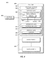
- FIG 4 is an illustration of an exemplary metal matrix composite material 400 that may be used in the outermost layer 302 of the structural substrate 300 according to an embodiment of the disclosure.
- the metal matrix composite material 400 comprises metal matrix composite tape 402 that is configured to conduct electrical current to make resistive heaters that also provide structural strength.
- the metal matrix composite tape 402 can generate heat by passage of an electric current therethrough, or can generate heat by bimetal electric heating using two metals and passing electric current between the two metals.
- Resistivity of the metal matrix composite tape 402 can be controlled to allow the heater and EME protection layer to be suitably combined.
- the resistivity of the metal matrix composite tape 402 can be controlled by suitably choosing a type of metal used in the metal matrix composite tape 402.
- Unprocessed metal matrix composite tape 404 is also shown in Figure 4 .
- Riblets 510 can be produced on the metal matrix composite tape 402 to reduce fluid dynamic drag on surfaces of a vehicle.
- riblets 510 can be produced on the metal matrix composite tape 402 to reduce fluid dynamic drag on a surface such as the wing 502 of the aircraft 500 ( Figure 5 ) as explained below.
- Combining heater and/or EME layers such as the riblets 510 with a structural part such as a skin panel of the wing 502 can produce a near weight neutral system.
- Figure 5 is an illustration of an exemplary aircraft 500 showing a structural substrate 300 used as a heater and as portions of surfaces of the aircraft 500 according to an embodiment of the disclosure.
- riblets 510 can be produced on the metal matrix composite tape 402 to reduce fluid dynamic drag on a surface such as the wing 502 of the aircraft 500.
- the riblets 510 may be oriented to be parallel with a side of a fuselage 508. Orientation of the riblets 510 on the wing 502, for example, varies based on speed and thus size of the wing 502.
- the riblets 510 may be aligned with a center line 504 of an engine nacelle 506 to reduce fluid dynamic drag.
- the riblets 510 may comprise grooves 512.
- the riblets 510 on the wing 502 reduce skin-friction drag from turbulent boundary-layer airflow. Thereby, the riblets 510 may save fuel and reduce emissions.
- the riblets 510 may constrain airflow and limit spanwise interaction, reducing drag.
- the riblets 510 may be used in conjunction with laminar flow to reduce skin-friction drag. Areas of the aircraft 500 where laminar flow may be difficult to sustain and a boundary layer may be turbulent can be covered by the riblets 510.
- FIG. 6 is an illustration of an exemplary schematic block diagram of an ice protection system 600 (system 600) according to an embodiment of the disclosure.
- System 600 comprises an electrical power source 602, a structure 606, and at least one structural substrate 300.
- System 600 may have functions, material, and structures that are similar to the embodiments shown in Figures 1-5 . Therefore common features, functions, and elements may not be redundantly described here.
- the structural substrate 300 is explained in the context of discussion of Figure 3 above.
- the structural substrate 300 is configured to act as a heater element for electrically heating the structure 606.
- Any number of heater elements such as a heater element 1 to a heater element N (where N is an integer) may be used for heating the structure 606.
- Heater elements 1-N and structural substrate 300 may be used in this document interchangeably.
- the electrical power source 602 may be a ground power supply comprising industry standard ground power cables (160 kVA), or other power cables suitable for heating various surfaces of the structure 606.
- System 600 may employ a wiring scheme operable for rapid power cycling to heat each of the heater elements 1-N on each section of the structure 606 individually maintaining a desired melt temp.
- a heater grid may be divided into 20 sections to deice the wing 502.
- the wiring scheme may comprise, for example but without limitation, capacitors, inductors, and/or other wiring scheme.
- the electrical power source 602 may also comprise an in-flight generator with adequate electrical power using in-flight power cables suitable for heating various surfaces of the structure 606 in-flight.
- the structure 606 may comprise a lifting surface, a control surface, or other surface.
- the lifting surface may comprise for example but without limitation, a wing, a fuselage and/or other lifting surface
- the control surface may comprise for example but without limitation, a horizontal stabilizer, a vertical stabilizer, a spoiler, an aileron, an elevon, an elevator, a flap, and/or other control surface.
- the structural substrate 300 may be integrated/designed in to the structure 606 such as the wing 502 of the aircraft 500.
- An electrical current 610 can be applied through the electrically conductive metal matrix composite 308 to enable deicing and preclude icing of, for example, the wing 502.
- the electrically conductive metal matrix composite 308 is configured as part of a surface of the wing 502 and may be grounded to an electric ground 612 to provide electromagnetic effect protection in the electrically conductive metal matrix composite 308. In this manner, the electrically conductive metal matrix composite 308 is grounded to the rest of the aircraft 500.
- the outermost layer 302 may comprise the riblets 510 to reduce fluid dynamic drag on an outer surface of the structure 606 such as an outer surface of the wing 502.
- the system 600 may comprise any number of processor modules, any number of processing modules, any number of memory modules, any number of electrical power sources, any number of control switches, and any number of buses suitable for their operation described herein.
- the illustrated system 600 depicts a simple embodiment for ease of description. These and other elements of the system 600 are interconnected together, allowing communication between the various elements of system 600. In one embodiment, these and other elements of the system 600 may be interconnected together via a bus 608.
- FIG. 7 is an illustration of an exemplary flowchart showing a process 700 for configuring a ground ice protection system using the structural substrate 300 according to an embodiment of the disclosure.
- the various tasks performed in connection with the process 700 may be performed by software, hardware, firmware, a computer-readable medium having computer executable instructions for performing the process method, or any combination thereof.
- the process 700 may be recorded in a computer-readable medium such as a semiconductor memory, a magnetic disk, an optical disk, and the like, and can be accessed and executed, for example, by a computer CPU such as processor module in which the computer-readable medium is stored.
- process 700 may include any number of additional or alternative tasks, the tasks shown in Figure 7 need not be performed in the illustrated order, and process 700 may be incorporated into a more comprehensive procedure or process having additional functionality not described in detail herein.
- portions of the process 700 may be performed by different elements of the system 600 such as: the electrical power source 602, the structure 606, and the structural substrate 300, etc.
- Process 700 may have functions, material, and structures that are similar to the embodiments shown in Figures 1-6 . Therefore common features, functions, and elements may not be redundantly described here.
- Process 700 may begin by configuring an innermost layer such as the innermost layer 306 comprising a composite such as the composite 312 to form a structural component such as the structural substrate 300 (task 702).
- Process 700 may continue by coupling an intermediate layer such as the intermediate layer 304 comprising an electrical insulator such as the electrical insulator 310 to the innermost layer 306 (task 704).
- Process 700 may continue by coupling an outermost layer such as the outermost layer 302 to the intermediate layer 304, the outermost layer 302 comprising an electrically conductive metal matrix composite such as the electrically conductive metal matrix composite 308 operable to conduct electricity to provide electric heating (task 706).
- an outermost layer such as the outermost layer 302
- the outermost layer 302 comprising an electrically conductive metal matrix composite such as the electrically conductive metal matrix composite 308 operable to conduct electricity to provide electric heating (task 706).
- the intermediate layer 304 and the innermost layer 306 are coupled together (e.g., via pressing together) and then the outermost layer 302 is coupled to the intermediate layer 304 (e.g., via pressing together).
- the outermost layer 302 and the intermediate layer 304 are coupled together (e.g., via pressing together) and then the innermost layer 306 is coupled (e.g., via pressing together) to the intermediate layer 304.
- the outermost layer 302 and the intermediate layer 304 coupled and the innermost layer 306 are coupled together substantially simultaneously (e.g., via pressing together).
- Coupling the intermediate layer 304 to the innermost layer 306, and coupling the outermost layer 302 to the intermediate layer 304 may be via, for example but without limitation, pressing, bonding, adhering, gluing, welding, fusing (e.g., mechanically), a combination thereof, or other suitable coupling.
- the outermost layer 302, the intermediate layer 304, and the innermost layer 306 are coupled and cured together to form a single integrated multi-layer structural component such as the structural substrate 300 that provides combined layers of structural layer, heating layer and/or electromagnetic effect (EME) protection layer that can form a surface of a vehicle such as the wing 502 as a single piece or as a single structural component as compared to 2 to 3 separate pieces of the existing systems that are cured and used separately.
- EME electromagnetic effect
- Process 700 may continue by configuring the intermediate layer 304 to electrically insulate the outermost layer 302 from the innermost layer 306 (task 708).
- Process 700 may continue by grounding the electrically conductive metal matrix composite 308 to provide electromagnetic effect protection in the electrically conductive metal matrix composite 308 (task 710).
- Process 700 may continue by configuring the outermost layer 302 to comprise riblets such as the riblets 510 operable to reduce aerodynamic drag on an outer surface such as the wing 502 (task 712).
- FIG. 8 is an illustration of an exemplary flowchart showing a process 800 for operating a ground ice protection system according to an embodiment of the disclosure.
- the various tasks performed in connection with the process 800 may be performed by software, hardware, firmware, a computer-readable medium having computer executable instructions for performing the process method, or any combination thereof.
- the process 800 may be recorded in a computer-readable medium such as a semiconductor memory, a magnetic disk, an optical disk, and the like, and can be accessed and executed, for example, by a computer CPU such as a processor module in which the computer-readable medium is stored.
- process 800 may include any number of additional or alternative tasks, the tasks shown in Figure 8 need not be performed in the illustrated order, and process 800 may be incorporated into a more comprehensive procedure or process having additional functionality not described in detail herein.
- portions of the process 800 may be performed by different elements of the system 600 such as: the electrical power source 602, the structure 606, and the structural substrate 300, etc.
- Process 800 may have functions, material, and structures that are similar to the embodiments shown in Figures 1-6 . Therefore common features, functions, and elements may not be redundantly described here.
- Process 800 may begin by providing structural functionality via an innermost layer such as the innermost layer 306 comprising a composite such as the composite 312 (task 802).
- the structural functionality may comprise for example but without limitation, bending, support, and other function.
- Process 800 may continue by electrically heating an outermost layer such as the outermost layer 302 comprising an electrically conductive metal matrix composite such as the electrically conductive metal matrix composite 308 by conducting electricity through the outermost layer 302 (task 804).
- Process 800 may continue by electrically insulating the outermost layer 302 from the innermost layer 306 via an intermediate layer such as the intermediate layer 304 comprising an electrical insulator such as the electrical insulator 310 (task 806).
- Process 800 may continue by receiving an electromagnetic effect in the electrically conductive metal matrix composite 308 (task 808).
- Process 800 may continue by conducting the electromagnetic effect to an electrical ground such as the electric ground 612 to provide electromagnetic effect protection (task 810).
- Process 800 may continue by applying an electrical current through the electrically conductive metal matrix composite 308 to deice a surface (such as the wing 502) of an aircraft and preclude icing of the surface, wherein the structural substrate 300 comprises the surface (wing 502) (task 812).
- embodiments of the disclosure provide electric heating elements that can be used in an ice protection system that deices a vehicle such as an aircraft by warming surfaces of the vehicle.
- the ice protection system when used on ground reduces: deicing time, deicing fluid, deicing resources, deicing cost, gallons of deicing fluid in storm water generated per year, number of winter weather flight delays and cancellations and their effect on airline flight schedules, and aircraft non-optimality due to deicing. Additionally, the ground ice protection system can prevent ice buildup enhancing vehicle and deicing crew safety and substantially reduces a need for multi-truck deicing operations.
- module refers to software, firmware, hardware, and any combination of these elements for performing the associated functions described herein. Additionally, for purpose of discussion, the various modules are described as discrete modules; however, as would be apparent one of skilled in the art, two or more modules may be combined to form a single module that performs the associated functions according the embodiments of the present disclosure.
- connection means that one element/node/feature is directly joined to (or directly communicates with) another element/node/feature, and not necessarily mechanically.
- coupled means that one element/node/feature is directly or indirectly joined to (or directly or indirectly communicates with) another element/node/feature, and not necessarily mechanically.
- attachment means that one element/node/feature is directly mechanically joined, fused or force compressed by an application of heat and/or pressure "to another element/node/feature.
- a group of items linked with the conjunction "and” should not be read as requiring that each and every one of those items be present in the grouping, but rather should be read as “and/or” unless expressly stated otherwise.
- a group of items linked with the conjunction "or” should not be read as requiring mutual exclusivity among that group, but rather should also be read as “and/or” unless expressly stated otherwise.
- operble means able to be used, fit or ready for use or service, usable for a specific purpose, and capable of performing a recited or desired function described herein.
- operble means the system and/or the device is fully functional and calibrated, comprises elements for, and meets applicable operability requirements to perform a recited function when activated.
- operble means the system and/or the circuit is fully functional and calibrated, comprises logic for, and meets applicable operability requirements to perform a recited function when activated.
Landscapes
- Engineering & Computer Science (AREA)
- Ceramic Engineering (AREA)
- Aviation & Aerospace Engineering (AREA)
- Chemical & Material Sciences (AREA)
- Laminated Bodies (AREA)
- Surface Heating Bodies (AREA)
- Resistance Heating (AREA)
Claims (15)
- Strukturelles Substrat (300) für eine Struktur (606), wobei das Substrat aufweist:ein mehrlagiges Hybrid-Verbund-Material mit:einer äußersten Lage (302) mit einem elektrisch leitfähigen Metall-Matrix-Verbundstoff (308, 400), der Elektrizität zur Bereitstellung einer elektrischen Heizung leiten kann;einer Zwischenlage (304) mit einem elektrischen Isolator (310), der mit der äußersten Lage verbunden ist; undeiner innersten Lage (306) mit einem zweiten Verbundstoff (312), der mit der Zwischenlage verbunden ist, wobei die Zwischenlage vorgesehen ist, um die äußerste Lage elektrisch von der innersten Lage zu isolieren.
- Strukturelles Substrat (300) nach Anspruch 1, wobei der elektrisch leitfähige Metall-Matrix-Verbundstoff (308, 400) aufweist: eine Aluminiumlegierung, eine Titanlegierung, eine Stahllegierung, eine Magnesiumlegierung oder eine Kombination davon.
- Strukturelles Substrat (300) nach Anspruch 1 oder 2, wobei der elektrische Isolator (310) eine Faser aufweist, die aufweist: Glasfaser, glasfaserverstärktes Polymer, Keramik, Bor, Siliziumcarbit, oder eine Kombination davon.
- Strukturelles Substrat (300) nach einem der Ansprüche 1 bis 3, wobei der zweite Verbundstoff (312) ein carbonfaserverstärktes Polymer aufweist, mit einem Harz oder Harz und Härter, und ausgelegt ist, um aufzuweisen: ein Gewebe, ein unidirektionales Band, oder eine Kombination davon.
- Strukturelles Substrat (300) nach einem der Ansprüche 1 bis 4, wobei die äußerste Lage (302) Riblets (510) aufweist, die den aerodynamischen Widerstand auf einer äußeren Fläche reduzieren,
- Strukturelles Substrat (300) nach einem der Ansprüche 1 bis 5, wobei der elektrisch leitfähige Metall-Matrix-Verbundstoff (308, 400) einen Schutz gegen elektromagnetische Wirkung für ein Flugzeug (200, 500) bereitstellt.
- Verfahren (700) zum Ausbilden eines strukturellen Substrats (300) mit einem mehrlagigen Hybrid-Verbund-Material, wobei das Verfahren aufweist:Konfigurieren (702) einer innersten Lage (306) mit einem ersten Verbundstoff (312), um eine strukturelle Komponente zu bilden;Verbinden (704) einer Zwischenlage (304), die einen elektrischen Isolator (310) aufweist, mit der innersten Lage;Verbinden (706) einer äußersten Lage (302) mit der Zwischenlage, wobei die äußerste Lage einen elektrisch leitfähigen Metall-Matrix-Verbundstoff (308, 400) aufweist, um Elektrizität zur Bereitstellung einer elektrischen Heizung leiten zu können; undKonfigurieren (708) der Zwischenlage, um die äußerste Lage gegen die innerste Lage zu isolieren.
- Verfahren (700) nach Anspruch 7, ferner mit: Erden (710) des elektrisch leitfähigen Metall-Matrix-Verbundstoffs (308, 400), um einen Schutz gegen elektromagnetische Wirkung in dem elektrisch leitfähigen Metall-Matrix-Verbundstoff bereitzustellen.
- Verfahren (700) nach Anspruch 7 oder 8, ferner mit: Konfigurieren (712) der äußersten Lage (302), um Riblets (510) zu haben, die den fluiddynamischen Widerstand an der äußeren Fläche reduzieren.
- Verfahren (700) nach einem der Ansprüche 7 bis 9, wobei das elektrische Heizen umfasst: Widerstandsheizen, Bimetallheizen, Jouleheizen, Ohmsches Heizen oder eine Kombination davon.
- Verfahren (700) nach einem der Ansprüche 7 bis 10, wobei das strukturelle Substrat (300) auf einem Flügel (502) eines Flugzeugs (200, 500) platziert ist, und ein elektrischer Strom (610) durch den elektrisch leitfähigen Metall-Matrix-Verbundstoff (308, 400) geführt wird, um ein Enteisen zu ermöglichen und ein Vereisen des Flügels zu verhindern.
- Verfahren (800) zum Enteisen, indem ein strukturelles Substrat (300) verwendet wird, mit einem mehrlagigen Hybrid-Verbund-Material, wobei das Verfahren aufweist:Bereitstellen (802) einer strukturellen Funktionalität über eine innerste Lage (306), die einen ersten Verbundstoff (312) aufweist;elektrisches Erhitzen (804) einer äußersten Lage (302), die einen elektrisch leitfähigen Metall-Matrix-Verbundstoff (308, 400) aufweist, indem Elektrizität durch die äußerste Lage geleitet wird; undelektrisches Isolierten (806) der äußersten Lage von der innersten Lage über eine Zwischenlage (304), die einen elektrischen Isolator (310) aufweist.
- Verfahren (800) nach Anspruch 12, ferner mit:Empfangen (808) einer elektromagnetischen Wirkung in dem elektrisch leitfähigen Metall-Matrix-Verbundstoff (308, 400); undLeiten (810) der elektromagnetischen Wirkung an eine elektrische Masse (612), um einen Schutz gegen elektromagnetische Wirkungen bereitzustellen.
- Verfahren (800) nach Anspruch 12 oder 13, wobei der Schritt des elektrischen Heizens (806) ferner aufweist: Widerstandsheizen, Bimetallheizen, Jouleheizen, Ohmsches Heizen oder eine Kombination davon.
- Verfahren (800) nach einem der Ansprüche 12 bis 14, ferner mit: Zuführen (812) eines elektrischen Stroms (610) durch den elektrisch leitfähigen Metall-Matrix-Verbundstoff (308, 400), um eine Oberfläche eines Flugzeugs (200, 500) zu enteisen und ein Vereisen der Oberfläche zu verhindern, wenn das strukturelle Substrat (300) die Oberfläche aufweist.
Applications Claiming Priority (1)
| Application Number | Priority Date | Filing Date | Title |
|---|---|---|---|
| US13/763,706 US9253823B2 (en) | 2013-02-10 | 2013-02-10 | Metal matrix composite used as a heating element |
Publications (2)
| Publication Number | Publication Date |
|---|---|
| EP2764997A1 EP2764997A1 (de) | 2014-08-13 |
| EP2764997B1 true EP2764997B1 (de) | 2015-09-16 |
Family
ID=49766923
Family Applications (1)
| Application Number | Title | Priority Date | Filing Date |
|---|---|---|---|
| EP13196535.2A Active EP2764997B1 (de) | 2013-02-10 | 2013-12-10 | Als ein Heizelement verwendeter Metallmatrix-Verbundstoff |
Country Status (5)
| Country | Link |
|---|---|
| US (1) | US9253823B2 (de) |
| EP (1) | EP2764997B1 (de) |
| JP (1) | JP6482759B2 (de) |
| BR (1) | BR102014002158B1 (de) |
| CA (1) | CA2835956C (de) |
Families Citing this family (18)
| Publication number | Priority date | Publication date | Assignee | Title |
|---|---|---|---|---|
| US9193466B2 (en) * | 2012-07-13 | 2015-11-24 | Mra Systems, Inc. | Aircraft ice protection system and method |
| WO2014181186A2 (en) * | 2013-03-15 | 2014-11-13 | Amir Snir | Methods and system for deicing a surface |
| US10059429B2 (en) * | 2015-04-24 | 2018-08-28 | The Boeing Company | Embedded tear straps in metal structures |
| EP3147216B1 (de) * | 2015-09-23 | 2019-08-07 | Airbus Defence and Space GmbH | Elektrische enteisung für luftfahrzeuge |
| KR101905672B1 (ko) * | 2016-11-17 | 2018-10-10 | 한국항공우주연구원 | 금속 매트릭스 복합재의 전기적 발열을 이용한 제빙장치 |
| US11273622B2 (en) | 2016-12-14 | 2022-03-15 | The Boeing Company | Stiffening elements that comprise integral current flowpaths |
| US11014337B2 (en) | 2016-12-14 | 2021-05-25 | The Boeing Company | Laminate structures comprising fiber-reinforced thermoplastic prepreg plies |
| US11077644B2 (en) | 2016-12-14 | 2021-08-03 | The Boeing Company | Material systems and methods of manufacturing material systems |
| CN107061193B (zh) * | 2017-03-13 | 2023-08-15 | 浙江工业大学 | 一种多层结构复合的防冰除冰系统及其组装方法 |
| US11376811B2 (en) | 2018-07-03 | 2022-07-05 | Goodrich Corporation | Impact and knife cut resistant pre-impregnated woven fabric for aircraft heated floor panels |
| US10899427B2 (en) | 2018-07-03 | 2021-01-26 | Goodrich Corporation | Heated floor panel with impact layer |
| US10875623B2 (en) | 2018-07-03 | 2020-12-29 | Goodrich Corporation | High temperature thermoplastic pre-impregnated structure for aircraft heated floor panel |
| US11008109B2 (en) | 2018-07-16 | 2021-05-18 | The Boeing Company | Aircraft ice protection systems |
| KR102179070B1 (ko) | 2019-04-10 | 2020-11-16 | 서울대학교 산학협력단 | 줄열 직접 가열을 이용한 전도성 섬유 복합재의 선택적 가열 경화 방법 및 이를 위한 장치 |
| US11548648B2 (en) * | 2020-01-14 | 2023-01-10 | Goodrich Corporation | Robust power transmission |
| US12391389B2 (en) * | 2022-10-07 | 2025-08-19 | The Boeing Company | Systems and methods for deicing aircraft |
| US20250263171A1 (en) * | 2024-02-17 | 2025-08-21 | Goodrich Corporation | Integration of an ice protection system and an ice detector into a single line replaceable unit |
| US20250313956A1 (en) * | 2024-04-09 | 2025-10-09 | The Boeing Company | Systems and methods for preparing metal matrix composite substrates for subsequent treatment |
Family Cites Families (30)
| Publication number | Priority date | Publication date | Assignee | Title |
|---|---|---|---|---|
| US4029838A (en) | 1975-09-24 | 1977-06-14 | The United States Of America As Represented By The Administrator Of The National Aeronautics And Space Administration | Hybrid composite laminate structures |
| US4411380A (en) | 1981-06-30 | 1983-10-25 | The United States Of America As Represented By The Administrator Of The National Aeronautics And Space Administration | Metal matrix composite structural panel construction |
| GB2253185A (en) | 1991-03-01 | 1992-09-02 | Secr Defence | Reinforced alloy laminates |
| US5866272A (en) | 1996-01-11 | 1999-02-02 | The Boeing Company | Titanium-polymer hybrid laminates |
| US5934617A (en) | 1997-09-22 | 1999-08-10 | Northcoast Technologies | De-ice and anti-ice system and method for aircraft surfaces |
| FR2779314B1 (fr) | 1998-05-27 | 2000-08-04 | Eurocopter France | Dispositif de chauffage a elements resistifs d'un profil aerodynamique |
| WO2003069955A1 (en) * | 2002-02-11 | 2003-08-21 | The Trustees Of Dartmouth College | Systems and methods for modifying an ice-to-object interface |
| PL376400A1 (en) | 2003-01-23 | 2005-12-27 | H.C.Starck Inc. | Pre-plating surface treatments for enhanced galvanic-corrosion resistance |
| US6852273B2 (en) | 2003-01-29 | 2005-02-08 | Adma Products, Inc. | High-strength metal aluminide-containing matrix composites and methods of manufacture the same |
| US20040245395A1 (en) * | 2003-05-09 | 2004-12-09 | Wallace Randall W. | Aircraft ice protection system |
| US7115323B2 (en) | 2003-08-28 | 2006-10-03 | The Boeing Company | Titanium foil ply replacement in layup of composite skin |
| US20050175813A1 (en) | 2004-02-10 | 2005-08-11 | Wingert A. L. | Aluminum-fiber laminate |
| US7763833B2 (en) | 2004-03-12 | 2010-07-27 | Goodrich Corp. | Foil heating element for an electrothermal deicer |
| US7246773B2 (en) | 2004-05-06 | 2007-07-24 | Goodrich Coporation | Low power, pulsed, electro-thermal ice protection system |
| DE102006031436B4 (de) | 2006-07-07 | 2012-12-06 | Airbus Operations Gmbh | Strukturelement, Verfahren zur Herstellung eines derartigen Strukturelements und Flugzeug mit einem derartigen Strukturelement |
| NL2000232C2 (nl) | 2006-09-12 | 2008-03-13 | Gtm Consulting B V | Huidpaneel voor een vliegtuigromp. |
| US9133714B2 (en) | 2006-11-01 | 2015-09-15 | United Technologies Corporation | Titanium foil as a structural heater element |
| DE102007063608B4 (de) | 2007-05-23 | 2011-04-21 | Airbus Operations Gmbh | Verbund und Rumpfzellenabschnitt mit einem derartigen Verbund |
| JP2009107515A (ja) | 2007-10-31 | 2009-05-21 | Shin Meiwa Ind Co Ltd | 航空機の複合材製構造体の製造方法及びその構造体 |
| US8206823B2 (en) * | 2008-04-14 | 2012-06-26 | The Boeing Company | System and method for fabrication of integrated lightning strike protection material |
| US20100108661A1 (en) | 2008-10-31 | 2010-05-06 | United Technologies Corporation | Multi-layer heating assembly and method |
| US8678316B2 (en) * | 2009-01-29 | 2014-03-25 | The Boeing Company | Amorphous metal riblets |
| BRPI1014711A2 (pt) | 2009-04-27 | 2016-04-12 | Applied Nanostrctured Solutions Llc | aquecimento de resistência com base em cnt para descongelar estruturas de compósito |
| DE102009026655B3 (de) | 2009-06-03 | 2011-06-30 | Linde Aktiengesellschaft, 80331 | Verfahren zur Herstellung eines Metallmatrix-Verbundwerkstoffs, Metallmatrix-Verbundwerkstoff und seine Verwendung |
| US8464626B2 (en) | 2009-11-20 | 2013-06-18 | CPS Technologies Corp. | Multi-layer metal matrix composite armor with edge protection |
| US20110300358A1 (en) * | 2010-06-04 | 2011-12-08 | The Boeing Company | Shape memory alloy/fiber reinforced polymeric composite structures and method for forming |
| JP5638940B2 (ja) * | 2010-12-28 | 2014-12-10 | 帝人株式会社 | 繊維強化樹脂複合材料 |
| EP2687557B1 (de) * | 2011-03-17 | 2018-12-05 | Toray Industries, Inc. | Prepreg, verfahren zur herstellung des prepregs und kohlenstofffaserverstärktes verbundmaterial |
| DE102011119844A1 (de) | 2011-05-26 | 2012-12-13 | Eads Deutschland Gmbh | Verbundstruktur mit Eisschutzvorrichtung sowie Herstellverfahren |
| US9221544B2 (en) | 2011-09-20 | 2015-12-29 | The Boeing Company | Integrated surface thermal management system |
-
2013
- 2013-02-10 US US13/763,706 patent/US9253823B2/en active Active
- 2013-12-06 CA CA2835956A patent/CA2835956C/en active Active
- 2013-12-10 EP EP13196535.2A patent/EP2764997B1/de active Active
-
2014
- 2014-01-29 BR BR102014002158-2A patent/BR102014002158B1/pt active IP Right Grant
- 2014-02-05 JP JP2014020011A patent/JP6482759B2/ja active Active
Also Published As
| Publication number | Publication date |
|---|---|
| BR102014002158B1 (pt) | 2020-10-20 |
| US20140224782A1 (en) | 2014-08-14 |
| CA2835956C (en) | 2016-02-23 |
| BR102014002158A2 (pt) | 2014-11-04 |
| CA2835956A1 (en) | 2014-08-10 |
| EP2764997A1 (de) | 2014-08-13 |
| US9253823B2 (en) | 2016-02-02 |
| JP2014195990A (ja) | 2014-10-16 |
| JP6482759B2 (ja) | 2019-03-13 |
Similar Documents
| Publication | Publication Date | Title |
|---|---|---|
| CA2835956C (en) | Metal matrix composite used as a heating element | |
| US10368401B2 (en) | Multi-functional composite structures | |
| US10167550B2 (en) | Multi-functional composite structures | |
| EP2560867B2 (de) | Laminierter plasmaaktuator und verfahren zu seiner herstellung | |
| US8146861B2 (en) | Component with carbon nanotubes | |
| US9090043B2 (en) | Molybdenum composite hybrid laminates and methods | |
| Jones et al. | A route to sustainable aviation: A roadmap for the realization of aircraft components with electrical and structural multifunctionality | |
| JP5788314B2 (ja) | 一体型落雷防護材料の作成システムおよび方法 | |
| US8231080B2 (en) | Distributing power in systems having a composite structure | |
| EP3339013B1 (de) | Beheizte bodenplatten mit wärmeleitenden und elektrisch isolierendem gewebe | |
| EP3284680B1 (de) | Integriertes stromrückführungsnetzwerk in verbundstrukturen | |
| CA3040698A1 (en) | Structural component for an aircraft | |
| CA2890769C (en) | Methods and apparatus for use in forming a lightning protection system | |
| US10046528B2 (en) | Composite layers with exposed reinforcement | |
| EP4108572A1 (de) | Flugzeugmerkmal mit heizsystem aus laserinduziertem graphen | |
| Park | Aircraft De-Icing system using thermal conductive fibers | |
| US20250375946A1 (en) | Method for repairing composite structures for improved electromagnetic effects (eme) protection | |
| GB2544585A (en) | Heating system for electrothermal temperature control, and method for the production of said heating system |
Legal Events
| Date | Code | Title | Description |
|---|---|---|---|
| PUAI | Public reference made under article 153(3) epc to a published international application that has entered the european phase |
Free format text: ORIGINAL CODE: 0009012 |
|
| 17P | Request for examination filed |
Effective date: 20131210 |
|
| AK | Designated contracting states |
Kind code of ref document: A1 Designated state(s): AL AT BE BG CH CY CZ DE DK EE ES FI FR GB GR HR HU IE IS IT LI LT LU LV MC MK MT NL NO PL PT RO RS SE SI SK SM TR |
|
| AX | Request for extension of the european patent |
Extension state: BA ME |
|
| R17P | Request for examination filed (corrected) |
Effective date: 20140828 |
|
| RBV | Designated contracting states (corrected) |
Designated state(s): AL AT BE BG CH CY CZ DE DK EE ES FI FR GB GR HR HU IE IS IT LI LT LU LV MC MK MT NL NO PL PT RO RS SE SI SK SM TR |
|
| GRAP | Despatch of communication of intention to grant a patent |
Free format text: ORIGINAL CODE: EPIDOSNIGR1 |
|
| INTG | Intention to grant announced |
Effective date: 20150331 |
|
| GRAS | Grant fee paid |
Free format text: ORIGINAL CODE: EPIDOSNIGR3 |
|
| GRAA | (expected) grant |
Free format text: ORIGINAL CODE: 0009210 |
|
| AK | Designated contracting states |
Kind code of ref document: B1 Designated state(s): AL AT BE BG CH CY CZ DE DK EE ES FI FR GB GR HR HU IE IS IT LI LT LU LV MC MK MT NL NO PL PT RO RS SE SI SK SM TR |
|
| REG | Reference to a national code |
Ref country code: GB Ref legal event code: FG4D |
|
| REG | Reference to a national code |
Ref country code: CH Ref legal event code: EP |
|
| REG | Reference to a national code |
Ref country code: IE Ref legal event code: FG4D |
|
| REG | Reference to a national code |
Ref country code: AT Ref legal event code: REF Ref document number: 749473 Country of ref document: AT Kind code of ref document: T Effective date: 20151015 |
|
| REG | Reference to a national code |
Ref country code: DE Ref legal event code: R096 Ref document number: 602013003108 Country of ref document: DE |
|
| REG | Reference to a national code |
Ref country code: FR Ref legal event code: PLFP Year of fee payment: 3 |
|
| REG | Reference to a national code |
Ref country code: NL Ref legal event code: MP Effective date: 20150916 |
|
| PG25 | Lapsed in a contracting state [announced via postgrant information from national office to epo] |
Ref country code: LT Free format text: LAPSE BECAUSE OF FAILURE TO SUBMIT A TRANSLATION OF THE DESCRIPTION OR TO PAY THE FEE WITHIN THE PRESCRIBED TIME-LIMIT Effective date: 20150916 Ref country code: FI Free format text: LAPSE BECAUSE OF FAILURE TO SUBMIT A TRANSLATION OF THE DESCRIPTION OR TO PAY THE FEE WITHIN THE PRESCRIBED TIME-LIMIT Effective date: 20150916 Ref country code: LV Free format text: LAPSE BECAUSE OF FAILURE TO SUBMIT A TRANSLATION OF THE DESCRIPTION OR TO PAY THE FEE WITHIN THE PRESCRIBED TIME-LIMIT Effective date: 20150916 Ref country code: GR Free format text: LAPSE BECAUSE OF FAILURE TO SUBMIT A TRANSLATION OF THE DESCRIPTION OR TO PAY THE FEE WITHIN THE PRESCRIBED TIME-LIMIT Effective date: 20151217 Ref country code: NO Free format text: LAPSE BECAUSE OF FAILURE TO SUBMIT A TRANSLATION OF THE DESCRIPTION OR TO PAY THE FEE WITHIN THE PRESCRIBED TIME-LIMIT Effective date: 20151216 |
|
| REG | Reference to a national code |
Ref country code: LT Ref legal event code: MG4D |
|
| REG | Reference to a national code |
Ref country code: AT Ref legal event code: MK05 Ref document number: 749473 Country of ref document: AT Kind code of ref document: T Effective date: 20150916 |
|
| PG25 | Lapsed in a contracting state [announced via postgrant information from national office to epo] |
Ref country code: SE Free format text: LAPSE BECAUSE OF FAILURE TO SUBMIT A TRANSLATION OF THE DESCRIPTION OR TO PAY THE FEE WITHIN THE PRESCRIBED TIME-LIMIT Effective date: 20150916 Ref country code: HR Free format text: LAPSE BECAUSE OF FAILURE TO SUBMIT A TRANSLATION OF THE DESCRIPTION OR TO PAY THE FEE WITHIN THE PRESCRIBED TIME-LIMIT Effective date: 20150916 Ref country code: RS Free format text: LAPSE BECAUSE OF FAILURE TO SUBMIT A TRANSLATION OF THE DESCRIPTION OR TO PAY THE FEE WITHIN THE PRESCRIBED TIME-LIMIT Effective date: 20150916 |
|
| PG25 | Lapsed in a contracting state [announced via postgrant information from national office to epo] |
Ref country code: NL Free format text: LAPSE BECAUSE OF FAILURE TO SUBMIT A TRANSLATION OF THE DESCRIPTION OR TO PAY THE FEE WITHIN THE PRESCRIBED TIME-LIMIT Effective date: 20150916 |
|
| PG25 | Lapsed in a contracting state [announced via postgrant information from national office to epo] |
Ref country code: SK Free format text: LAPSE BECAUSE OF FAILURE TO SUBMIT A TRANSLATION OF THE DESCRIPTION OR TO PAY THE FEE WITHIN THE PRESCRIBED TIME-LIMIT Effective date: 20150916 Ref country code: ES Free format text: LAPSE BECAUSE OF FAILURE TO SUBMIT A TRANSLATION OF THE DESCRIPTION OR TO PAY THE FEE WITHIN THE PRESCRIBED TIME-LIMIT Effective date: 20150916 Ref country code: IS Free format text: LAPSE BECAUSE OF FAILURE TO SUBMIT A TRANSLATION OF THE DESCRIPTION OR TO PAY THE FEE WITHIN THE PRESCRIBED TIME-LIMIT Effective date: 20160116 Ref country code: CZ Free format text: LAPSE BECAUSE OF FAILURE TO SUBMIT A TRANSLATION OF THE DESCRIPTION OR TO PAY THE FEE WITHIN THE PRESCRIBED TIME-LIMIT Effective date: 20150916 Ref country code: IT Free format text: LAPSE BECAUSE OF FAILURE TO SUBMIT A TRANSLATION OF THE DESCRIPTION OR TO PAY THE FEE WITHIN THE PRESCRIBED TIME-LIMIT Effective date: 20150916 Ref country code: EE Free format text: LAPSE BECAUSE OF FAILURE TO SUBMIT A TRANSLATION OF THE DESCRIPTION OR TO PAY THE FEE WITHIN THE PRESCRIBED TIME-LIMIT Effective date: 20150916 |
|
| PG25 | Lapsed in a contracting state [announced via postgrant information from national office to epo] |
Ref country code: PL Free format text: LAPSE BECAUSE OF FAILURE TO SUBMIT A TRANSLATION OF THE DESCRIPTION OR TO PAY THE FEE WITHIN THE PRESCRIBED TIME-LIMIT Effective date: 20150916 Ref country code: BE Free format text: LAPSE BECAUSE OF NON-PAYMENT OF DUE FEES Effective date: 20151231 Ref country code: AT Free format text: LAPSE BECAUSE OF FAILURE TO SUBMIT A TRANSLATION OF THE DESCRIPTION OR TO PAY THE FEE WITHIN THE PRESCRIBED TIME-LIMIT Effective date: 20150916 Ref country code: PT Free format text: LAPSE BECAUSE OF FAILURE TO SUBMIT A TRANSLATION OF THE DESCRIPTION OR TO PAY THE FEE WITHIN THE PRESCRIBED TIME-LIMIT Effective date: 20160118 Ref country code: RO Free format text: LAPSE BECAUSE OF FAILURE TO SUBMIT A TRANSLATION OF THE DESCRIPTION OR TO PAY THE FEE WITHIN THE PRESCRIBED TIME-LIMIT Effective date: 20150916 |
|
| REG | Reference to a national code |
Ref country code: DE Ref legal event code: R097 Ref document number: 602013003108 Country of ref document: DE |
|
| PLBE | No opposition filed within time limit |
Free format text: ORIGINAL CODE: 0009261 |
|
| STAA | Information on the status of an ep patent application or granted ep patent |
Free format text: STATUS: NO OPPOSITION FILED WITHIN TIME LIMIT |
|
| PG25 | Lapsed in a contracting state [announced via postgrant information from national office to epo] |
Ref country code: MC Free format text: LAPSE BECAUSE OF FAILURE TO SUBMIT A TRANSLATION OF THE DESCRIPTION OR TO PAY THE FEE WITHIN THE PRESCRIBED TIME-LIMIT Effective date: 20150916 Ref country code: LU Free format text: LAPSE BECAUSE OF FAILURE TO SUBMIT A TRANSLATION OF THE DESCRIPTION OR TO PAY THE FEE WITHIN THE PRESCRIBED TIME-LIMIT Effective date: 20151210 |
|
| 26N | No opposition filed |
Effective date: 20160617 |
|
| PG25 | Lapsed in a contracting state [announced via postgrant information from national office to epo] |
Ref country code: DK Free format text: LAPSE BECAUSE OF FAILURE TO SUBMIT A TRANSLATION OF THE DESCRIPTION OR TO PAY THE FEE WITHIN THE PRESCRIBED TIME-LIMIT Effective date: 20150916 |
|
| REG | Reference to a national code |
Ref country code: IE Ref legal event code: MM4A |
|
| PG25 | Lapsed in a contracting state [announced via postgrant information from national office to epo] |
Ref country code: IE Free format text: LAPSE BECAUSE OF NON-PAYMENT OF DUE FEES Effective date: 20151210 |
|
| PG25 | Lapsed in a contracting state [announced via postgrant information from national office to epo] |
Ref country code: SI Free format text: LAPSE BECAUSE OF FAILURE TO SUBMIT A TRANSLATION OF THE DESCRIPTION OR TO PAY THE FEE WITHIN THE PRESCRIBED TIME-LIMIT Effective date: 20150916 |
|
| REG | Reference to a national code |
Ref country code: FR Ref legal event code: PLFP Year of fee payment: 4 |
|
| PG25 | Lapsed in a contracting state [announced via postgrant information from national office to epo] |
Ref country code: BE Free format text: LAPSE BECAUSE OF FAILURE TO SUBMIT A TRANSLATION OF THE DESCRIPTION OR TO PAY THE FEE WITHIN THE PRESCRIBED TIME-LIMIT Effective date: 20150916 |
|
| PG25 | Lapsed in a contracting state [announced via postgrant information from national office to epo] |
Ref country code: BG Free format text: LAPSE BECAUSE OF FAILURE TO SUBMIT A TRANSLATION OF THE DESCRIPTION OR TO PAY THE FEE WITHIN THE PRESCRIBED TIME-LIMIT Effective date: 20150916 Ref country code: HU Free format text: LAPSE BECAUSE OF FAILURE TO SUBMIT A TRANSLATION OF THE DESCRIPTION OR TO PAY THE FEE WITHIN THE PRESCRIBED TIME-LIMIT; INVALID AB INITIO Effective date: 20131210 |
|
| PG25 | Lapsed in a contracting state [announced via postgrant information from national office to epo] |
Ref country code: CY Free format text: LAPSE BECAUSE OF FAILURE TO SUBMIT A TRANSLATION OF THE DESCRIPTION OR TO PAY THE FEE WITHIN THE PRESCRIBED TIME-LIMIT Effective date: 20150916 |
|
| REG | Reference to a national code |
Ref country code: CH Ref legal event code: PL |
|
| PG25 | Lapsed in a contracting state [announced via postgrant information from national office to epo] |
Ref country code: MT Free format text: LAPSE BECAUSE OF FAILURE TO SUBMIT A TRANSLATION OF THE DESCRIPTION OR TO PAY THE FEE WITHIN THE PRESCRIBED TIME-LIMIT Effective date: 20150916 |
|
| PG25 | Lapsed in a contracting state [announced via postgrant information from national office to epo] |
Ref country code: LI Free format text: LAPSE BECAUSE OF NON-PAYMENT OF DUE FEES Effective date: 20161231 Ref country code: CH Free format text: LAPSE BECAUSE OF NON-PAYMENT OF DUE FEES Effective date: 20161231 |
|
| REG | Reference to a national code |
Ref country code: FR Ref legal event code: PLFP Year of fee payment: 5 |
|
| PG25 | Lapsed in a contracting state [announced via postgrant information from national office to epo] |
Ref country code: SM Free format text: LAPSE BECAUSE OF FAILURE TO SUBMIT A TRANSLATION OF THE DESCRIPTION OR TO PAY THE FEE WITHIN THE PRESCRIBED TIME-LIMIT Effective date: 20150916 |
|
| PG25 | Lapsed in a contracting state [announced via postgrant information from national office to epo] |
Ref country code: MK Free format text: LAPSE BECAUSE OF FAILURE TO SUBMIT A TRANSLATION OF THE DESCRIPTION OR TO PAY THE FEE WITHIN THE PRESCRIBED TIME-LIMIT Effective date: 20150916 |
|
| PG25 | Lapsed in a contracting state [announced via postgrant information from national office to epo] |
Ref country code: AL Free format text: LAPSE BECAUSE OF FAILURE TO SUBMIT A TRANSLATION OF THE DESCRIPTION OR TO PAY THE FEE WITHIN THE PRESCRIBED TIME-LIMIT Effective date: 20150916 Ref country code: TR Free format text: LAPSE BECAUSE OF FAILURE TO SUBMIT A TRANSLATION OF THE DESCRIPTION OR TO PAY THE FEE WITHIN THE PRESCRIBED TIME-LIMIT Effective date: 20150916 |
|
| P01 | Opt-out of the competence of the unified patent court (upc) registered |
Effective date: 20230516 |
|
| PGFP | Annual fee paid to national office [announced via postgrant information from national office to epo] |
Ref country code: GB Payment date: 20251229 Year of fee payment: 13 |
|
| PGFP | Annual fee paid to national office [announced via postgrant information from national office to epo] |
Ref country code: FR Payment date: 20251226 Year of fee payment: 13 |
|
| PGFP | Annual fee paid to national office [announced via postgrant information from national office to epo] |
Ref country code: DE Payment date: 20251229 Year of fee payment: 13 |