EP2765254A1 - Dispositif d'enroulement pour voiles d'ombrage, marquises et analogues - Google Patents
Dispositif d'enroulement pour voiles d'ombrage, marquises et analogues Download PDFInfo
- Publication number
- EP2765254A1 EP2765254A1 EP14153618.5A EP14153618A EP2765254A1 EP 2765254 A1 EP2765254 A1 EP 2765254A1 EP 14153618 A EP14153618 A EP 14153618A EP 2765254 A1 EP2765254 A1 EP 2765254A1
- Authority
- EP
- European Patent Office
- Prior art keywords
- surface element
- cable system
- shaft
- cable
- winding
- Prior art date
- Legal status (The legal status is an assumption and is not a legal conclusion. Google has not performed a legal analysis and makes no representation as to the accuracy of the status listed.)
- Granted
Links
- 238000004804 winding Methods 0.000 claims abstract description 63
- 230000000903 blocking effect Effects 0.000 claims abstract description 61
- 238000005096 rolling process Methods 0.000 claims abstract description 49
- 230000033001 locomotion Effects 0.000 claims description 9
- 238000010276 construction Methods 0.000 description 9
- 230000006835 compression Effects 0.000 description 7
- 238000007906 compression Methods 0.000 description 7
- 230000008901 benefit Effects 0.000 description 6
- 230000000694 effects Effects 0.000 description 5
- 230000008859 change Effects 0.000 description 3
- 238000006073 displacement reaction Methods 0.000 description 3
- 229910000831 Steel Inorganic materials 0.000 description 2
- 230000009471 action Effects 0.000 description 2
- 239000000872 buffer Substances 0.000 description 2
- 239000010959 steel Substances 0.000 description 2
- 230000004913 activation Effects 0.000 description 1
- 230000002238 attenuated effect Effects 0.000 description 1
- 230000005540 biological transmission Effects 0.000 description 1
- 230000005484 gravity Effects 0.000 description 1
- 230000001771 impaired effect Effects 0.000 description 1
- 238000000034 method Methods 0.000 description 1
- 239000004033 plastic Substances 0.000 description 1
- 238000007665 sagging Methods 0.000 description 1
- 210000002023 somite Anatomy 0.000 description 1
- 230000037072 sun protection Effects 0.000 description 1
Images


Classifications
-
- E—FIXED CONSTRUCTIONS
- E04—BUILDING
- E04F—FINISHING WORK ON BUILDINGS, e.g. STAIRS, FLOORS
- E04F10/00—Sunshades, e.g. Florentine blinds or jalousies; Outside screens; Awnings or baldachins
- E04F10/02—Sunshades, e.g. Florentine blinds or jalousies; Outside screens; Awnings or baldachins of flexible canopy materials, e.g. canvas ; Baldachins
- E04F10/06—Sunshades, e.g. Florentine blinds or jalousies; Outside screens; Awnings or baldachins of flexible canopy materials, e.g. canvas ; Baldachins comprising a roller-blind with means for holding the end away from a building
- E04F10/0644—Sunshades, e.g. Florentine blinds or jalousies; Outside screens; Awnings or baldachins of flexible canopy materials, e.g. canvas ; Baldachins comprising a roller-blind with means for holding the end away from a building with mechanisms for unrolling or balancing the blind
- E04F10/0648—Sunshades, e.g. Florentine blinds or jalousies; Outside screens; Awnings or baldachins of flexible canopy materials, e.g. canvas ; Baldachins comprising a roller-blind with means for holding the end away from a building with mechanisms for unrolling or balancing the blind acting on the roller tube
-
- E—FIXED CONSTRUCTIONS
- E04—BUILDING
- E04F—FINISHING WORK ON BUILDINGS, e.g. STAIRS, FLOORS
- E04F10/00—Sunshades, e.g. Florentine blinds or jalousies; Outside screens; Awnings or baldachins
- E04F10/02—Sunshades, e.g. Florentine blinds or jalousies; Outside screens; Awnings or baldachins of flexible canopy materials, e.g. canvas ; Baldachins
- E04F10/06—Sunshades, e.g. Florentine blinds or jalousies; Outside screens; Awnings or baldachins of flexible canopy materials, e.g. canvas ; Baldachins comprising a roller-blind with means for holding the end away from a building
- E04F10/0666—Accessories
- E04F10/0681—Support posts for the movable end of the blind
-
- E—FIXED CONSTRUCTIONS
- E04—BUILDING
- E04H—BUILDINGS OR LIKE STRUCTURES FOR PARTICULAR PURPOSES; SWIMMING OR SPLASH BATHS OR POOLS; MASTS; FENCING; TENTS OR CANOPIES, IN GENERAL
- E04H15/00—Tents or canopies, in general
- E04H15/32—Parts, components, construction details, accessories, interior equipment, specially adapted for tents, e.g. guy-line equipment, skirts, thresholds
- E04H15/58—Closures; Awnings; Sunshades
Definitions
- the invention relates to a rolling device for awnings, sun sails, internal sun protection devices, surface blinds, horizontal awnings, darkening and / or similar surface elements
- a rolling device for awnings, sun sails, internal sun protection devices, surface blinds, horizontal awnings, darkening and / or similar surface elements comprising a rotatably mounted shaft, on the shaft or about the shaft up and unwindable flexible surface element, a circulating cable system with engages a first portion at a free end of the surface element and is coupled with a second portion and unrolled to the shaft, a drive for rotating the shaft and / or for winding and unrolling of the surface element and the cable system.
- the invention particularly relates to constructions in which at least one flexible surface element is provided on and unwound on a shaft, wherein in the unwound state, the surface element is stretched, so that it has a certain stability.
- the technical field of the invention relates in particular to structures such as awning devices, awning devices and retractable rain canopy devices, which include, for example, awnings, awnings and the like.
- awning devices are known in which a flexible surface element can be wound around an axis. Furthermore, a rope is provided which acts on a free end of the surface element in order to tension the surface element on the one hand and on the other hand to unwind from an axis. It has been found to be advantageous if the cable system is performed circumferentially. This means that the attacking at the free end of the surface element rope is returned via deflection to the shaft to be wound up there. Advantage of this design is that when extending and retracting the surface element, the free end of the cable system is automatically wound up again, and not separately stowed or wound by hand.
- the prior art awning devices with circumferential cable system have in common that the cable system and / or the surface element is constantly kept under train. This tension is necessary according to the prior art, so that the surface element has a certain basic tension in order to increase the stability.
- Spring systems act on the cable system.
- a disadvantage of these constructions is that the spring force acts against the rolling movement of the surface element.
- such surface elements are often rolled out by rotating a shaft via a drive. Now acts the spring force against the rolling movement of the surface element, it also acts against the force of the drive.
- the drive must be dimensioned more powerful, or it must be provided a gear with a larger gear ratio.
- a larger translation is associated with an uncomfortable operation, as more revolutions are necessary to extend the surface element.
- a smaller gear ratio would increase the power to roll out the sail, which also makes operation more difficult.
- the object of the invention is therefore to provide a rolling device for awnings, awnings and the like, which is practicable in use, in particular low driving forces needed and / or fast off and retractable and beyond represents a simplification of the construction.
- the improved practicability also includes the automatic winding of the cable system.
- the object of the invention is achieved, on the one hand, by providing a tensioning system for tensioning the surface element, and in that the tensioning system can be relaxed for winding and unwinding the surface element, so that the surface element and the cable system are substantially strain-relieved or tension-free for winding and unwinding or
- the cable system during winding and unwinding of the surface element has an excess length and is thus substantially relieved of strain and that when winding the surface element, the difference between wound length of the surface element and unwound length of the cable system is smaller than the excess length of the cable system or that at Unwinding of the surface element, the difference between unwound length of the surface element and rolled-up length of the cable system is smaller than the excess length of the cable system.
- the tensioning system comprises a blocking device for blocking the cable system or the free end of the surface element, that the cable system is returned to the shaft deflected at least by a deflection means, wherein the deflection means is preferably designed as a deflection roller and / or that the blocking device Rope clamp, a rope clamp on a pulley, a lockable pulley, a detachable mechanical connection, an acting against the clamping force reeling of the cable system on the shaft, a mechanical connection of the cable system with the Shaft or a releasable mechanical connection of the free end of the surface element comprises.
- the deflection means is preferably designed as a deflection roller and / or that the blocking device Rope clamp, a rope clamp on a pulley, a lockable pulley, a detachable mechanical connection, an acting against the clamping force reeling of the cable system on the shaft, a mechanical connection of the cable system with the Shaft or a releasable mechanical connection of the
- the device is designed such that both the surface element and the cable system by rotation of the shaft on this up and unwound and / or up and unrolled and that the surface element by rotation of the shaft and winding of the surface element with blocked cable system or blocked free end of the surface element is tensioned, that the surface element, in particular in unwound position, by rotation of the shaft in an arbitrary direction of rotation can be wound and tensioned and / or that the clamping system comprises a releasable locking device for fixing a third cable section of the cable system and / or that the blocking device and the third cable section are arranged in the course of the cable system between the first cable section and the second cable section.
- the clamping system is provided a rotation blocking device for blocking a rotation of the shaft against the caused by the tension of the surface element torque or against the tension exerted by the cable system
- the rotation blocking device preferably as a self-locking gear, as a self-locking drive, as a self-locking worm gear
- the surface element is wound around a first winding circumference that the cable system is wound around a second winding circumference, preferably that the first winding circumference is greater than or equal to the second winding circumference and / or that during unwinding of the surface element, the unwound length of the surface element is greater than or equal to the rolled-up length of the cable system and / or that in the course of the cable system
- an elastic tensioning element is arranged, which is spanned at beneficianele ment acts with a clamping force against the tension of the surface element and / or the cable system and that acting against the tension
- the wound-up length of the surface element is greater than or equal to the excess length of that section of the cable system which lies between the blocking device and the free end of the surface element.
- the device according to the invention comprises a flexible surface element, which has a certain tension in the clamped state in order to increase the stability.
- Tension-free surface elements that are substantially strain-relieved or de-energized would sag freely.
- the stability for example, against wind forces, would not be given on the one hand endangers the safety and on the other hand brings unpleasant side effects such as noise and changing position of the surface element with it.
- a clamping system is provided according to the invention.
- this clamping system is designed to achieve the object according to the invention such that, despite the tension of the rolled surface element, the handling of the device is not impaired.
- the tensioning system for winding and unwinding of the flexible surface element is deactivated, deactivated, relaxed, relaxed or relieved. This means that the surface element is stretched and / or tensioned in the extended state via the clamping system.
- the tension is reduced or reduced in such a way that the surface element and / or the cable system is substantially relieved of tension or de-energized.
- a stress state in which the tensioning system is deactivated and / or relaxed is defined as essentially tensionless.
- the cable system and / or the surface element With a relaxed tensioning system, the cable system and / or the surface element is exposed to little or no tensile stress.
- Femer is given by elastic design of the rope of the cable system a certain basic tension.
- this basic voltage and / or a tension of the tensionless state is many times lower than the tension with a tensioned surface element.
- the cable system has an excess length and is thereby relaxed.
- the cable of the cable system is longer by the extra length than the shortest possible route of the cable system between the curl on the shaft and the junction with the surface element. Only upon activation of the clamping system and / or the blocking device and rotation of the shaft by the drive, this excess length is at least partially compensated or tensioned.
- this facilitates the rolling up and unwinding of the surface element on the shaft, since no tension force acts against the drive torque.
- a weaker drive and / or a smaller ratio of the drive can be selected.
- a significantly faster rolling up and unrolling of the surface element is possible with the same force.
- an electric drive such as an electric motor or the like, a faster winding and unrolling of the surface element allows.
- an elastic tensioning element can be provided.
- an elastic clamping element which limits the mechanical load of the cable system and the surface element within certain limits.
- an elastic clamping element may be provided according to the invention, which is against the clamping force of Rope system and / or the surface element acts. If the tension of the system now increases, for example as a result of a gust of wind, the elastic tensioning element will yield. This reduces the voltage or at least the gradient of the voltage increase and the voltage spike, which would otherwise act unrestrained on the system, is attenuated and / or cushioned.
- the clamping element is designed for example as a gas spring, gas spring, steel spring, flexible support or as a rubber buffer.
- the tensioning system comprises means which are adapted, on the one hand, to increase the tension in the clamped state and, on the other hand, to be able to relieve the cable system and / or the surface element.
- the cable system basically comprises several sections. With a first section, the cable system engages a free end of the surface element. Furthermore, the cable system is preferably deflected by deflecting means such as deflection rollers and the like and guided back to the shaft.
- the shaft about which the surface element can be wound up is set up or suitable for winding up a second cable section of the cable system as well.
- a cable drum can be provided on the shaft. On this cable drum, the cable system can be rolled up and down. Preferably, this cable drum can be rotationally rigidly connected to the shaft.
- a cable system which engages with a first cable section at a free end of the surface element and is coupled to a second cable section and uncoilable coupled to the shaft.
- the cable system is preferably returned to the shaft by a deflection means, such as a deflection roller.
- the circumferential cable system is designed such that the surface element is wound around a first winding circumference, that the cable system is wound around a second winding circumference.
- the device may be designed such that the first winding circumference is greater than or equal to the second winding circumference.
- the unwound length of the surface element is larger or essentially the same size as the rolled-up length of the cable system and the winding of the surface element, the wound-up length of the surface element is greater or substantially equal to the unrolled length of the cable system.
- the winding circumference of the surface element changes with increasing winding.
- the smallest winding circumference preferably corresponds to the circumference of the shaft.
- the cable system is preferably not wound up in a multi-layered manner, but rolled up adjacent to one another in a helical manner.
- the winding circumference of the cable system is substantially constant, while the winding circumference of the surface element depends on the wound-up length of the surface element.
- the winding circumference of the cable preferably corresponds to the circumference of the cable drum or the circumference of the shaft.
- the ratio is selected such that the unwinding of the surface element, the cable system does not or only slightly spans or that relax the cable system and the surface element during unwinding.
- the device is designed such that when winding the surface element, the difference between wound length of the surface element and unwound length of the cable system is smaller than the excess length of the cable system or that during unwinding of the surface element, the difference between unwound length of the surface element and rolled length of the cable system is smaller than the excess length of the cable system.
- the rolling device is designed such that the wound-up length of the surface element is greater than or equal to the excess length of that portion of the cable system which lies between the blocking device and the free end of the surface element.
- the clamping system is adapted to be able to cause a voltage of the rolled surface element on the one hand, but on the other hand to allow a substantially tensionless winding and unwinding of the surface element.
- a blocking device is provided for fixing a third cable section.
- This blocking device is provided in the course of the cable system, in particular between the first and the second cable section.
- the blocking device according to the invention can be used, for example, as a fixing device, e.g. Rope clamp, be designed as a mechanical, releasable connection means for the rope or other impact-like structures.
- a fixing device e.g. Rope clamp
- the effect of the blocking device is that the corresponding portion of the cable system or the surface element is stationary or at least relatively fixed in place or that the force acting on the cable system clamping force of the surface element is counteracted.
- Fixed in place is in particular a blocking or fixation relative to the environment or one of the fastening points.
- the tensioning system preferably comprises a rotation blocking device for blocking the shaft.
- a rotation blocking device for blocking the shaft.
- a rotation blocking device is provided for blocking a rotation of the shaft against the torque caused by the tension or against the tension exerted by the cable system.
- This can for example be designed as a self-locking gear, as a self-locking gear drive, as a self-locking drive, as a mechanical connection means, as a ratchet or the like.
- the rolling device according to the invention can be configured in different embodiments.
- two substantially diametrically oppositely oriented surface elements can be wound up and unwound from the shaft. This would correspond to a common construction of a solar sail.
- essentially square surface elements can be unilaterally unwound in order to essentially correspond to the function of an awning.
- These have, according to one embodiment, two free ends, wherein in each case at a free end Rope portion of the circulating cable system is provided.
- a plurality of cable systems may be provided to return a plurality of free ends of the surface elements to the shaft.
- the cable system may comprise deflection rollers, which are in turn connected to cables for their part.
- the invention is characterized in that the surface wound on the shaft in a winding surface element is unwound by rotation of the shaft in one direction, and that for tensioning the surface element, the shaft is further rotated in fully unwound surface element in the same direction or is quizcard, so on the one hand the surface element is wound on the shaft in the opposite winding direction, and on the other hand simultaneously the cable system and in particular the second cable section are further rolled on the shaft, whereby the reeling of the cable system acts against the winding of the surface element.
- the tensioning system comprises the circumferential cable system, the drive for rotating the shaft and the surface element, wherein the surface element is adapted to be wound in fully unwound position in the opposite winding direction on the shaft and thereby against the rolling movement the rope system to act so that the blocking device is designed as acting against the clamping force curl of the cable system on the shaft and / or as a mechanical connection of the cable system with the shaft.
- Fig. 1 shows a schematic oblique view of a rolling device according to the invention with a shaft 1, which is rotatably supported on both sides provided at fastening points 14.
- the attachment points 14 are designed as pillars, which are for example firmly anchored in the ground.
- On the shaft two surface elements 2 are provided. These are connected and unwound connected to the shaft 1. They have a substantially triangular shape, wherein at the respective free ends 5 of the two surface elements 2, the cable system 3 attacks.
- the cable system 3 comprises a first cable section 4, which is connected to the free end 5 of the surface element and / or acts on this.
- the cable system 3 comprises a second cable section 6, which is connected to the shaft 1 so that it can be wound up and unwound.
- a drive 7 is provided via which the shaft can be turned. This rotation causes on the one hand a winding and unwinding of the surface elements and the winding and unwinding of the cable system, in particular of the second cable section. 6
- the cable sections adjoining the two first cable sections 4 are brought together at a connection point 15 and are preferably connected via a deflection means 12 to a single cable, at whose connection point 15 opposite end the second cable section 6 is provided.
- a deflection means 12 are provided according to the present embodiment. Examples of such deflection means are rollers, rollers, deflection bolts or the like. Preferably, rollers and in particular rotatably mounted rollers are used.
- a tensioning element 13 is provided in the course of the cable system in the present embodiment.
- the clamping element 13 is preferably designed as an elastic clamping element and comprises an elastic body which opposes a change in length of a certain spring force.
- the cable system is guided in the region of the free ends 5 and / or in the region of the first cable sections 4 about deflecting means 12, which are provided at further fastening points 14.
- These attachment points can be designed, for example, as anchored in the ground uprights or supports.
- a design as a wall anchor, column, hook or the like is possible.
- the rolling device comprises a tensioning system 8.
- the tensioning system 8 comprises one or more components which are suitable for tensioning the surface element or maintaining and / or generating a tensioning force.
- the clamping system according to the invention is suitable for enabling a substantially tensionless winding and unwinding of the surface element or of the surface elements.
- the clamping system 8 comprises a blocking device 9.
- the blocking device 9 is suitable and / or adapted to fix a third cable section 10 of the cable system 3.
- the third cable section 10 is fixed in place by the blocking device 9. This fixation takes place, for example, at the fastening point 14 or at a rigidly connected to the attachment point 14 position.
- the clamping system 8 comprises a rotation blocking device 11, which is suitable and / or adapted to block a rotation of the shaft due to the tension of the cable system and / or the surface elements.
- Possible embodiments for the blocking devices are cable clamps, mechanical cable clamps, releasable mechanical connection means and other constructions which are suitable for temporarily fixing the third cable section in a substantially stationary manner.
- the Drehblocklervorides 11 of all embodiments is designed for example as a self-locking gear, self-locking drive, self-locking gear drive, ratchet, mechanical rotation blocking device or other device that is adapted to prevent rotation of the shaft against the surface element acting forces.
- the drive itself can be performed according to all embodiments of the invention, for example, as an electric rotary drive, as an electric drive, as a wheel drive, as a crank drive, as a mechanical hand crank with worm gear or similar constructions.
- the drive on a worm gear, which is self-locking.
- Fig. 2 essentially shows the Fig. 1 corresponding embodiment of the rolling device according to the invention in a schematic representation.
- two surface elements 2 are provided wound on a shaft 1.
- At the free ends 5 of the surface elements 2 each engage a first cable section 4 of the cable system 3.
- the shaft is rotatably mounted at fastening points 14 and rotatably driven by a drive 7 and / or driven.
- a blocking device 9 and a tensioning element 13 are provided in the course of the cable system 3.
- the cable system 3 is executed circumferentially. This means that when the surface elements are unwound and wound up, the ends that become free as a result are rolled up again.
- the rope sections acting on the surface elements 2 are brought together at a connection point 15 and connected to a further, second cable section 6, which can be wound around the shaft 1.
- the merging of the two cable sections is done in the present embodiment by a further deflection 12.
- the two cable sections can also be connected to each other via fixed connection means.
- Fig. 3a shows a further embodiment of a rolling device according to the invention in a schematic representation.
- Surface elements 2 are up and unwound on a shaft 1 is provided, which is rotatably mounted in a preferred manner and rotatably arranged drivable.
- a drive 7 and attachment points 14 are provided.
- the device comprises a circulating cable system 3, which according to the preceding description with first Sellabroughen 4 at the free ends 5 of the surface elements 2 attack and are guided over deflecting means 12 to the shaft.
- the cable system 3 comprises two second cable sections 6, which can be rolled up by rotation of the shaft on the same.
- the clamping system according to the invention 8 comprises two blocking devices 9 for fixing each of the two third cable sections 10.
- the two blocking devices 9 may also be merged or coupled so that be fixed by the operation of a device both third cable sections 10.
- Fig. 3a shows a rolling device according to the invention in an extended position, that is, with unwound surface element and / or unwound surface elements.
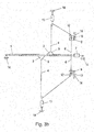
- Fig. 3b shows the same device as Fig. 3a , but with retracted surface elements or wound surface elements.
- the tension of the surface elements 2 may also act against the clamping elements 13. These are at all Embodiments preferred between deflecting means 12 and attachment points 14 are provided.
- the tensioning system 8 When the tensioning system 8 has been activated and / or the state of tension is substantially tension-relieved, the tensioning elements 13 are arranged essentially without effect or without tension in the course of the cable section.
- Fig. 4 shows a further embodiment of a rolling device according to the invention.
- a shaft 1 is rotatably mounted at attachment points 14 is provided.
- a drive 7 is set up and / or suitable for winding or unwinding a surface element 2 via a rotation of the shaft 1 and for winding or unrolling a cable system 3.
- the surface element 2 comprises two free ends 5. At these two free ends 5 each first cable sections 4 of the cable system 8 attack.
- the cable system is returned to the shaft 1 via deflecting means 12.
- the mode of action essentially corresponds to the rolling devices of FIGS. 1 to 3 ,
- the cable system 3 is designed such that two second cable sections 6 are wound or wound on two different locations on or around the shaft.
- the two second cable sections 6 can be brought together and wound up at only one point on or around the shaft.
- a clamping system 8 the blocking devices 9 for fixing third cable sections 10 has.
- a rotation blocking device 11 which are designed to be substantially equivalent in effect to the rotation blocking device of the preceding embodiments.
- self-locking gear units, self-locking drives or mechanical locking devices are used.
- the embodiment of the Figure 4 is of their mode of action and of the operation of the clamping system 8 has the same effect as the previous embodiments
- Fig. 5 shows a possible clamping element 13 in a schematic sectional view, as it can be used for example in the previous embodiments.
- the clamping element 13 comprises a first point of attack 16 and a second point of attack 17.
- the first point of attack 16 is connected to a fixed attachment point 14 and the second point of attack 17, for example, with a deflection 12.
- the first point of attack 16 is rigidly connected Main body 18, in which a punch 20 is linearly guided and / or stored.
- the stamp has at its second attack point 17 opposite region on a plate 21.
- the main body 18 is provided with a shutter 19 through which the punch 20 is passed. Between the plates 21 and the shutter 19, a compression spring 22 is provided. This compression spring has a certain spring constant and / or a certain spring characteristic.
- the compression spring 22 is provided biased between the plate 21 and the shutter 19 in the main body 18.
- a force for displacement of the second point of attack 17 relative to the first point of attack 16 is necessary, which is greater than the spring force of the compression spring 22 in this biased state. If the spring force is exceeded, for example, by a mechanical force acting on the surface element, then the second point of application 17 is displaced relative to the first point of application 16. By further tension of the compression spring, the force increases. However, the voltage spike is cushioned by the movement and displacement of the two points of attack to each other.
- the biasing force of the spring or the tensioning element is chosen such that it is greater than that force which is exerted by the cable system on the tensioning element 13 by the statically tensioned surface elements.
- Designated as a compression spring elastic element of the clamping element 13 may be replaced or supplemented according to the invention and in all embodiments by similar elastic means.
- Examples are tension springs which are loaded with tension or rubber buffers as well as similar and equivalent elastic elements.
- the blocking device 9 can be designed according to the invention as a device which is suitable and / or adapted to fix a cable section stationary at least temporarily.
- devices which are used for example, in all embodiments can also be used Sailboats are known as sheet clamps. These devices have clamping bodies through which the cable and / or the cable system is passed. The cable can be moved freely in one direction. If the rope is moved in the opposite direction, the device automatically locks and the corresponding cable section is fixed.
- Advantage of such a construction in combination with the present invention is that for unwinding the surface elements and simultaneously rolling the cable, the rope can be passed unhindered through the sheet clamp.
- the direction of rotation of the drive is reversed according to the above description.
- the blocking device can be arranged in the region of that attachment point at which the drive 7 is arranged. As a result, the operation is easier.
- the surface element can be rolled out and stretched by a person.
- the blocking device 9 may be provided on the post of the device. Actuators for the drive may also be provided in this area. Examples include a hand crank with mechanical drive or switch to activate an electric drive.
- a cable or cable is an element or a combination of several elements which are suitable for carrying out the functions according to the invention.
- the term rope also includes belts, straps, straps, steel cables, plastic cables, rod-shaped elements, chain-like elements and the like.
- the blocking device is designed as a fixable deflection roller, as a cable clamp on a deflection roller or as a lockable deflection roller.
- a lever is provided which clamps the cable between the guide roller and a cam located on the lever. This fixes the rope in this area.
- the blocking device is arranged at that deflection roller, which is arranged along the cable system 3 closest to the free end 5 of the surface element 2.
- the cable system acts on the said deflection means 12 or the fastening points 14 like a pulley, whereby the forces acting on these elements during tensioning act, are increased.
- the blocking device 9 is arranged before the deflection of the sill system 3 or during the deflection of the cable system 3, this additional load for the named elements is eliminated.
- This embodiment is thus characterized in that the blocking device 9 of the preceding embodiments is provided in that deflection roller, which is arranged in the course of the cable system immediately before the free end of the surface element 2, or of which the cable system preferably directly to the free end 5 of the surface element. 2 is diverted.
- this blocking device 9 is designed as a cable clamp on the deflection means 12 for fixing the rope.
- no separate blocking device 9 is provided.
- the surface element 2 of the shaft 1 and simultaneously winding the cable system on the shaft 1 the surface element 2 is unwound from the shaft 1 until it is completely unwound. If now the shaft 1 is further rotated in the same direction via the drive 7, then the surface element 2 winds again on the shaft in the opposite direction of winding. In contrast to this winding direction, however, the cable system 3 and in particular the second cable section 6 is further wound on the shaft. Thus, the curl of the cable system acts against the winding of the surface element 2. Dies results in a tension of the surface element 2 and the cable system 3.
- the tensioning system 8 thus comprises the circumferential cable system 3 according to the previous embodiments and a drive and a surface element 2, which is suitable and / or set up in opposite winding direction on the shaft to be wound while acting against the rolling motion of the cable system.
- the blocking device 9 is designed as acting against the clamping force reeling of the cable system on the shaft or as a mechanical connection of the cable system with the shaft.
- the rolling device for awning is designed such that in the course of the cable system 3, an elastic clamping element 13 is arranged, which acts on spanned surface element 2 with a clamping force against the tension of the surface element 2 and / or the cable system 3 and that against the tension of the surface element 2 and / or the cable system 3 acting clamping force of the clamping element 13 during winding and unrolling of the surface element 2 is substantially zero.
- the rolling device can in particular be designed such that the surface element 2, in particular in the unwound position, can be wound and tensioned in any desired direction of rotation by rotation of the shaft 1.
- Bzgz 51 727 1 wave 2 surface element 3 cable system 4 first rope section 5 free end 6 second rope section 7 drive 8th clamping system 9 blocking device 10 third rope section 11
Landscapes
- Engineering & Computer Science (AREA)
- Architecture (AREA)
- Civil Engineering (AREA)
- Structural Engineering (AREA)
- Transmission Devices (AREA)
- Storing, Repeated Paying-Out, And Re-Storing Of Elongated Articles (AREA)
Applications Claiming Priority (1)
| Application Number | Priority Date | Filing Date | Title |
|---|---|---|---|
| ATA50099/2013A AT513936B1 (de) | 2013-02-08 | 2013-02-08 | Rollvorrichtung für Sonnensegel, Markisen und dergleichen |
Publications (2)
| Publication Number | Publication Date |
|---|---|
| EP2765254A1 true EP2765254A1 (fr) | 2014-08-13 |
| EP2765254B1 EP2765254B1 (fr) | 2016-08-03 |
Family
ID=50072900
Family Applications (1)
| Application Number | Title | Priority Date | Filing Date |
|---|---|---|---|
| EP14153618.5A Not-in-force EP2765254B1 (fr) | 2013-02-08 | 2014-02-03 | Dispositif d'enroulement pour voiles d'ombrage, marquises et analogues |
Country Status (2)
| Country | Link |
|---|---|
| EP (1) | EP2765254B1 (fr) |
| AT (1) | AT513936B1 (fr) |
Cited By (4)
| Publication number | Priority date | Publication date | Assignee | Title |
|---|---|---|---|---|
| IT201800002763A1 (it) * | 2018-02-16 | 2019-08-16 | Roberto Bettega | Sistema di copertura e ombreggiatura di un'area del suolo |
| EP3572597A1 (fr) * | 2018-05-10 | 2019-11-27 | Bega S.r.l. | Ensemble d'auvent pour pare-soleil et de préférence un pare-soleil à voile |
| IT201900019175A1 (it) * | 2019-10-17 | 2021-04-17 | Bega S R L | Sistema di protezione di un'area mediante un telo parasole relativo kit e metodo |
| WO2025172546A1 (fr) * | 2024-02-14 | 2025-08-21 | Plaspack Netze Gmbh | Dispositif pour enrouler et dérouler un élément plat souple et dispositif d'ombrage comprenant ce dispositif |
Families Citing this family (1)
| Publication number | Priority date | Publication date | Assignee | Title |
|---|---|---|---|---|
| DE102021101419A1 (de) | 2021-01-22 | 2022-07-28 | Warema Renkhoff Se | Sonnenschutzanlage mit einem Zugsystem |
Citations (8)
| Publication number | Priority date | Publication date | Assignee | Title |
|---|---|---|---|---|
| DE8522704U1 (de) * | 1985-08-07 | 1985-10-24 | Reflexa-Werke H.P. Albrecht GmbH & Co KG, 8871 Rettenbach | Sonnen- und/oder Wetterschutzvorrichtung |
| DE4036892A1 (de) * | 1990-11-20 | 1992-05-21 | Weiermann Dieter Weinor | Spannvorrichtung fuer ein flexibles, flaechiges abdeckmittel |
| DE19614640A1 (de) * | 1996-04-13 | 1997-10-16 | Warema Renkhoff Gmbh & Co Kg | Windsicherung für Senkrechtmarkisen |
| DE202005001875U1 (de) * | 2005-02-05 | 2005-05-19 | Rewalux Markisenvertrieb Gmbh | Verstellbares Sonnensegel mit einer Plane |
| DE202006004615U1 (de) * | 2005-03-21 | 2006-06-14 | Vajsman, Peter | Sonnenschutzvorrichtung |
| EP1914365A2 (fr) * | 2006-10-10 | 2008-04-23 | WAREMA Renkhoff GmbH | Installation de protection contre le soleil ou la pluie |
| AT11817U2 (de) * | 2010-01-12 | 2011-05-15 | Trs Sonnenschutz Und Steuerungstechnik Gmbh | Schutzvorrichtung, insbesondere aufrollbares sonnensegel |
| DE202009018220U1 (de) * | 2008-03-11 | 2011-08-01 | Plaspack Netze Gmbh | Spannvorrichtung für ein von einer Wickelwelle abziehbares Sonnensegel |
Family Cites Families (1)
| Publication number | Priority date | Publication date | Assignee | Title |
|---|---|---|---|---|
| DE10218572A1 (de) * | 2002-04-26 | 2003-11-06 | Schmitz Werke | Markise, insbesondere Wintergartenmarkise |
-
2013
- 2013-02-08 AT ATA50099/2013A patent/AT513936B1/de not_active IP Right Cessation
-
2014
- 2014-02-03 EP EP14153618.5A patent/EP2765254B1/fr not_active Not-in-force
Patent Citations (8)
| Publication number | Priority date | Publication date | Assignee | Title |
|---|---|---|---|---|
| DE8522704U1 (de) * | 1985-08-07 | 1985-10-24 | Reflexa-Werke H.P. Albrecht GmbH & Co KG, 8871 Rettenbach | Sonnen- und/oder Wetterschutzvorrichtung |
| DE4036892A1 (de) * | 1990-11-20 | 1992-05-21 | Weiermann Dieter Weinor | Spannvorrichtung fuer ein flexibles, flaechiges abdeckmittel |
| DE19614640A1 (de) * | 1996-04-13 | 1997-10-16 | Warema Renkhoff Gmbh & Co Kg | Windsicherung für Senkrechtmarkisen |
| DE202005001875U1 (de) * | 2005-02-05 | 2005-05-19 | Rewalux Markisenvertrieb Gmbh | Verstellbares Sonnensegel mit einer Plane |
| DE202006004615U1 (de) * | 2005-03-21 | 2006-06-14 | Vajsman, Peter | Sonnenschutzvorrichtung |
| EP1914365A2 (fr) * | 2006-10-10 | 2008-04-23 | WAREMA Renkhoff GmbH | Installation de protection contre le soleil ou la pluie |
| DE202009018220U1 (de) * | 2008-03-11 | 2011-08-01 | Plaspack Netze Gmbh | Spannvorrichtung für ein von einer Wickelwelle abziehbares Sonnensegel |
| AT11817U2 (de) * | 2010-01-12 | 2011-05-15 | Trs Sonnenschutz Und Steuerungstechnik Gmbh | Schutzvorrichtung, insbesondere aufrollbares sonnensegel |
Cited By (5)
| Publication number | Priority date | Publication date | Assignee | Title |
|---|---|---|---|---|
| IT201800002763A1 (it) * | 2018-02-16 | 2019-08-16 | Roberto Bettega | Sistema di copertura e ombreggiatura di un'area del suolo |
| EP3527741A1 (fr) * | 2018-02-16 | 2019-08-21 | Roberto Bettega | Systeme de couverture et d'ombrage d'une zone au sol |
| EP3572597A1 (fr) * | 2018-05-10 | 2019-11-27 | Bega S.r.l. | Ensemble d'auvent pour pare-soleil et de préférence un pare-soleil à voile |
| IT201900019175A1 (it) * | 2019-10-17 | 2021-04-17 | Bega S R L | Sistema di protezione di un'area mediante un telo parasole relativo kit e metodo |
| WO2025172546A1 (fr) * | 2024-02-14 | 2025-08-21 | Plaspack Netze Gmbh | Dispositif pour enrouler et dérouler un élément plat souple et dispositif d'ombrage comprenant ce dispositif |
Also Published As
| Publication number | Publication date |
|---|---|
| AT513936B1 (de) | 2015-04-15 |
| AT513936A1 (de) | 2014-08-15 |
| EP2765254B1 (fr) | 2016-08-03 |
Similar Documents
| Publication | Publication Date | Title |
|---|---|---|
| EP2765254B1 (fr) | Dispositif d'enroulement pour voiles d'ombrage, marquises et analogues | |
| EP1188591A1 (fr) | Store à rouleau de fenêtre pour vitres de véhicule courbées ou non rectangulaires | |
| EP2817471B1 (fr) | Dispositif d'enroulement et déroulement d'une bande de matière sur et à partir d'un arbre | |
| DE202005001875U1 (de) | Verstellbares Sonnensegel mit einer Plane | |
| AT506083B1 (de) | Spannvorrichtung für ein von einer wickelwelle abziehbares sonnensegel | |
| EP3260623B1 (fr) | Store enrouleur | |
| DE3841139C2 (de) | Sonnenschutzanlage für flächige Glasabdeckungen, insbesondere Wintergartendächer | |
| DE102013008252B4 (de) | Sonnensegel mit Aufwicklung | |
| EP2864557A1 (fr) | Élément de toiture convertible, toiture et procédé d'utilisation de l'élément de toiture | |
| DE102006047899C5 (de) | Sonnen- und Regenschutzanlage | |
| DE202005012612U1 (de) | Planendach | |
| DE202006004615U1 (de) | Sonnenschutzvorrichtung | |
| DE102021101419A1 (de) | Sonnenschutzanlage mit einem Zugsystem | |
| DE102011009273A1 (de) | Befestigungsmast mit zahnradübersetztem Handkurbelantrieb für die Befestigung von textilen Sonnensegeln | |
| DE60036966T2 (de) | Methode und vorrichtung zum antreiben und lagern einer abdeckung | |
| DE102018003626B4 (de) | Bedachungsinstallation zur Verwendung als Sonnen- und Regenschutz | |
| EP1936062B1 (fr) | Guidage d'un profilé d'extension | |
| DE102022106755A1 (de) | Wickelvorrichtung zur Verwendung an einer Sonnenschutzeinrichtung | |
| EP3061887B1 (fr) | Dispositif de protection contre le soleil | |
| EP4603655A1 (fr) | Système pour enrouler et dérouler une bande de matériau | |
| DE102005038464A1 (de) | Beschattungsvorrichtung | |
| CH716865B1 (de) | Anordnung umfassend ein Schwimmbecken und ein Abdecksystem für das Schwimmbecken | |
| DE10063454B4 (de) | Vorrichtung zum Verschließen und/oder Beschatten eines Öffnungsquerschnitts bzw. einer Fläche | |
| DE202007009937U1 (de) | Beschattungsplane zum Beschatten eines lichtdurchlässigen Flächenelements | |
| DE202015100293U1 (de) | Vorrichtung zum Schutz einer Gebäudeöffnung |
Legal Events
| Date | Code | Title | Description |
|---|---|---|---|
| PUAI | Public reference made under article 153(3) epc to a published international application that has entered the european phase |
Free format text: ORIGINAL CODE: 0009012 |
|
| 17P | Request for examination filed |
Effective date: 20140203 |
|
| AK | Designated contracting states |
Kind code of ref document: A1 Designated state(s): AL AT BE BG CH CY CZ DE DK EE ES FI FR GB GR HR HU IE IS IT LI LT LU LV MC MK MT NL NO PL PT RO RS SE SI SK SM TR |
|
| AX | Request for extension of the european patent |
Extension state: BA ME |
|
| R17P | Request for examination filed (corrected) |
Effective date: 20150129 |
|
| RBV | Designated contracting states (corrected) |
Designated state(s): AL AT BE BG CH CY CZ DE DK EE ES FI FR GB GR HR HU IE IS IT LI LT LU LV MC MK MT NL NO PL PT RO RS SE SI SK SM TR |
|
| GRAP | Despatch of communication of intention to grant a patent |
Free format text: ORIGINAL CODE: EPIDOSNIGR1 |
|
| INTG | Intention to grant announced |
Effective date: 20160224 |
|
| GRAS | Grant fee paid |
Free format text: ORIGINAL CODE: EPIDOSNIGR3 |
|
| GRAA | (expected) grant |
Free format text: ORIGINAL CODE: 0009210 |
|
| AK | Designated contracting states |
Kind code of ref document: B1 Designated state(s): AL AT BE BG CH CY CZ DE DK EE ES FI FR GB GR HR HU IE IS IT LI LT LU LV MC MK MT NL NO PL PT RO RS SE SI SK SM TR |
|
| REG | Reference to a national code |
Ref country code: GB Ref legal event code: FG4D Free format text: NOT ENGLISH |
|
| REG | Reference to a national code |
Ref country code: CH Ref legal event code: EP Ref country code: AT Ref legal event code: REF Ref document number: 817444 Country of ref document: AT Kind code of ref document: T Effective date: 20160815 |
|
| REG | Reference to a national code |
Ref country code: IE Ref legal event code: FG4D Free format text: LANGUAGE OF EP DOCUMENT: GERMAN |
|
| REG | Reference to a national code |
Ref country code: DE Ref legal event code: R096 Ref document number: 502014001203 Country of ref document: DE |
|
| REG | Reference to a national code |
Ref country code: NL Ref legal event code: FP |
|
| REG | Reference to a national code |
Ref country code: CH Ref legal event code: NV Representative=s name: FREI PATENTANWALTSBUERO AG, CH |
|
| REG | Reference to a national code |
Ref country code: LT Ref legal event code: MG4D |
|
| PG25 | Lapsed in a contracting state [announced via postgrant information from national office to epo] |
Ref country code: HR Free format text: LAPSE BECAUSE OF FAILURE TO SUBMIT A TRANSLATION OF THE DESCRIPTION OR TO PAY THE FEE WITHIN THE PRESCRIBED TIME-LIMIT Effective date: 20160803 Ref country code: FI Free format text: LAPSE BECAUSE OF FAILURE TO SUBMIT A TRANSLATION OF THE DESCRIPTION OR TO PAY THE FEE WITHIN THE PRESCRIBED TIME-LIMIT Effective date: 20160803 Ref country code: IS Free format text: LAPSE BECAUSE OF FAILURE TO SUBMIT A TRANSLATION OF THE DESCRIPTION OR TO PAY THE FEE WITHIN THE PRESCRIBED TIME-LIMIT Effective date: 20161203 Ref country code: IT Free format text: LAPSE BECAUSE OF FAILURE TO SUBMIT A TRANSLATION OF THE DESCRIPTION OR TO PAY THE FEE WITHIN THE PRESCRIBED TIME-LIMIT Effective date: 20160803 Ref country code: RS Free format text: LAPSE BECAUSE OF FAILURE TO SUBMIT A TRANSLATION OF THE DESCRIPTION OR TO PAY THE FEE WITHIN THE PRESCRIBED TIME-LIMIT Effective date: 20160803 Ref country code: NO Free format text: LAPSE BECAUSE OF FAILURE TO SUBMIT A TRANSLATION OF THE DESCRIPTION OR TO PAY THE FEE WITHIN THE PRESCRIBED TIME-LIMIT Effective date: 20161103 Ref country code: LT Free format text: LAPSE BECAUSE OF FAILURE TO SUBMIT A TRANSLATION OF THE DESCRIPTION OR TO PAY THE FEE WITHIN THE PRESCRIBED TIME-LIMIT Effective date: 20160803 |
|
| REG | Reference to a national code |
Ref country code: FR Ref legal event code: PLFP Year of fee payment: 4 |
|
| PG25 | Lapsed in a contracting state [announced via postgrant information from national office to epo] |
Ref country code: SE Free format text: LAPSE BECAUSE OF FAILURE TO SUBMIT A TRANSLATION OF THE DESCRIPTION OR TO PAY THE FEE WITHIN THE PRESCRIBED TIME-LIMIT Effective date: 20160803 Ref country code: GR Free format text: LAPSE BECAUSE OF FAILURE TO SUBMIT A TRANSLATION OF THE DESCRIPTION OR TO PAY THE FEE WITHIN THE PRESCRIBED TIME-LIMIT Effective date: 20161104 Ref country code: PL Free format text: LAPSE BECAUSE OF FAILURE TO SUBMIT A TRANSLATION OF THE DESCRIPTION OR TO PAY THE FEE WITHIN THE PRESCRIBED TIME-LIMIT Effective date: 20160803 Ref country code: LV Free format text: LAPSE BECAUSE OF FAILURE TO SUBMIT A TRANSLATION OF THE DESCRIPTION OR TO PAY THE FEE WITHIN THE PRESCRIBED TIME-LIMIT Effective date: 20160803 Ref country code: ES Free format text: LAPSE BECAUSE OF FAILURE TO SUBMIT A TRANSLATION OF THE DESCRIPTION OR TO PAY THE FEE WITHIN THE PRESCRIBED TIME-LIMIT Effective date: 20160803 Ref country code: PT Free format text: LAPSE BECAUSE OF FAILURE TO SUBMIT A TRANSLATION OF THE DESCRIPTION OR TO PAY THE FEE WITHIN THE PRESCRIBED TIME-LIMIT Effective date: 20161205 |
|
| PG25 | Lapsed in a contracting state [announced via postgrant information from national office to epo] |
Ref country code: RO Free format text: LAPSE BECAUSE OF FAILURE TO SUBMIT A TRANSLATION OF THE DESCRIPTION OR TO PAY THE FEE WITHIN THE PRESCRIBED TIME-LIMIT Effective date: 20160803 Ref country code: EE Free format text: LAPSE BECAUSE OF FAILURE TO SUBMIT A TRANSLATION OF THE DESCRIPTION OR TO PAY THE FEE WITHIN THE PRESCRIBED TIME-LIMIT Effective date: 20160803 |
|
| REG | Reference to a national code |
Ref country code: DE Ref legal event code: R097 Ref document number: 502014001203 Country of ref document: DE |
|
| PG25 | Lapsed in a contracting state [announced via postgrant information from national office to epo] |
Ref country code: CZ Free format text: LAPSE BECAUSE OF FAILURE TO SUBMIT A TRANSLATION OF THE DESCRIPTION OR TO PAY THE FEE WITHIN THE PRESCRIBED TIME-LIMIT Effective date: 20160803 Ref country code: DK Free format text: LAPSE BECAUSE OF FAILURE TO SUBMIT A TRANSLATION OF THE DESCRIPTION OR TO PAY THE FEE WITHIN THE PRESCRIBED TIME-LIMIT Effective date: 20160803 Ref country code: SK Free format text: LAPSE BECAUSE OF FAILURE TO SUBMIT A TRANSLATION OF THE DESCRIPTION OR TO PAY THE FEE WITHIN THE PRESCRIBED TIME-LIMIT Effective date: 20160803 Ref country code: SM Free format text: LAPSE BECAUSE OF FAILURE TO SUBMIT A TRANSLATION OF THE DESCRIPTION OR TO PAY THE FEE WITHIN THE PRESCRIBED TIME-LIMIT Effective date: 20160803 Ref country code: BG Free format text: LAPSE BECAUSE OF FAILURE TO SUBMIT A TRANSLATION OF THE DESCRIPTION OR TO PAY THE FEE WITHIN THE PRESCRIBED TIME-LIMIT Effective date: 20161103 |
|
| PLBE | No opposition filed within time limit |
Free format text: ORIGINAL CODE: 0009261 |
|
| STAA | Information on the status of an ep patent application or granted ep patent |
Free format text: STATUS: NO OPPOSITION FILED WITHIN TIME LIMIT |
|
| 26N | No opposition filed |
Effective date: 20170504 |
|
| PG25 | Lapsed in a contracting state [announced via postgrant information from national office to epo] |
Ref country code: SI Free format text: LAPSE BECAUSE OF FAILURE TO SUBMIT A TRANSLATION OF THE DESCRIPTION OR TO PAY THE FEE WITHIN THE PRESCRIBED TIME-LIMIT Effective date: 20160803 |
|
| PG25 | Lapsed in a contracting state [announced via postgrant information from national office to epo] |
Ref country code: MC Free format text: LAPSE BECAUSE OF FAILURE TO SUBMIT A TRANSLATION OF THE DESCRIPTION OR TO PAY THE FEE WITHIN THE PRESCRIBED TIME-LIMIT Effective date: 20160803 |
|
| REG | Reference to a national code |
Ref country code: IE Ref legal event code: MM4A |
|
| PG25 | Lapsed in a contracting state [announced via postgrant information from national office to epo] |
Ref country code: LU Free format text: LAPSE BECAUSE OF NON-PAYMENT OF DUE FEES Effective date: 20170203 |
|
| REG | Reference to a national code |
Ref country code: FR Ref legal event code: PLFP Year of fee payment: 5 |
|
| PG25 | Lapsed in a contracting state [announced via postgrant information from national office to epo] |
Ref country code: IE Free format text: LAPSE BECAUSE OF NON-PAYMENT OF DUE FEES Effective date: 20170203 |
|
| PG25 | Lapsed in a contracting state [announced via postgrant information from national office to epo] |
Ref country code: MT Free format text: LAPSE BECAUSE OF FAILURE TO SUBMIT A TRANSLATION OF THE DESCRIPTION OR TO PAY THE FEE WITHIN THE PRESCRIBED TIME-LIMIT Effective date: 20160803 |
|
| GBPC | Gb: european patent ceased through non-payment of renewal fee |
Effective date: 20180203 |
|
| PG25 | Lapsed in a contracting state [announced via postgrant information from national office to epo] |
Ref country code: AL Free format text: LAPSE BECAUSE OF FAILURE TO SUBMIT A TRANSLATION OF THE DESCRIPTION OR TO PAY THE FEE WITHIN THE PRESCRIBED TIME-LIMIT Effective date: 20160803 |
|
| REG | Reference to a national code |
Ref country code: CH Ref legal event code: PCAR Free format text: NEW ADDRESS: POSTFACH, 8032 ZUERICH (CH) |
|
| PG25 | Lapsed in a contracting state [announced via postgrant information from national office to epo] |
Ref country code: GB Free format text: LAPSE BECAUSE OF NON-PAYMENT OF DUE FEES Effective date: 20180203 |
|
| PG25 | Lapsed in a contracting state [announced via postgrant information from national office to epo] |
Ref country code: HU Free format text: LAPSE BECAUSE OF FAILURE TO SUBMIT A TRANSLATION OF THE DESCRIPTION OR TO PAY THE FEE WITHIN THE PRESCRIBED TIME-LIMIT; INVALID AB INITIO Effective date: 20140203 |
|
| PG25 | Lapsed in a contracting state [announced via postgrant information from national office to epo] |
Ref country code: CY Free format text: LAPSE BECAUSE OF NON-PAYMENT OF DUE FEES Effective date: 20160803 |
|
| PG25 | Lapsed in a contracting state [announced via postgrant information from national office to epo] |
Ref country code: MK Free format text: LAPSE BECAUSE OF FAILURE TO SUBMIT A TRANSLATION OF THE DESCRIPTION OR TO PAY THE FEE WITHIN THE PRESCRIBED TIME-LIMIT Effective date: 20160803 |
|
| PG25 | Lapsed in a contracting state [announced via postgrant information from national office to epo] |
Ref country code: TR Free format text: LAPSE BECAUSE OF FAILURE TO SUBMIT A TRANSLATION OF THE DESCRIPTION OR TO PAY THE FEE WITHIN THE PRESCRIBED TIME-LIMIT Effective date: 20160803 |
|
| REG | Reference to a national code |
Ref country code: AT Ref legal event code: MM01 Ref document number: 817444 Country of ref document: AT Kind code of ref document: T Effective date: 20190203 |
|
| PG25 | Lapsed in a contracting state [announced via postgrant information from national office to epo] |
Ref country code: AT Free format text: LAPSE BECAUSE OF NON-PAYMENT OF DUE FEES Effective date: 20190203 |
|
| PGFP | Annual fee paid to national office [announced via postgrant information from national office to epo] |
Ref country code: NL Payment date: 20210217 Year of fee payment: 8 Ref country code: FR Payment date: 20210225 Year of fee payment: 8 Ref country code: CH Payment date: 20210208 Year of fee payment: 8 |
|
| PGFP | Annual fee paid to national office [announced via postgrant information from national office to epo] |
Ref country code: BE Payment date: 20210217 Year of fee payment: 8 |
|
| PGFP | Annual fee paid to national office [announced via postgrant information from national office to epo] |
Ref country code: DE Payment date: 20220131 Year of fee payment: 9 |
|
| REG | Reference to a national code |
Ref country code: NL Ref legal event code: MM Effective date: 20220301 |
|
| REG | Reference to a national code |
Ref country code: CH Ref legal event code: PL |
|
| REG | Reference to a national code |
Ref country code: BE Ref legal event code: MM Effective date: 20220228 |
|
| PG25 | Lapsed in a contracting state [announced via postgrant information from national office to epo] |
Ref country code: NL Free format text: LAPSE BECAUSE OF NON-PAYMENT OF DUE FEES Effective date: 20220301 Ref country code: FR Free format text: LAPSE BECAUSE OF NON-PAYMENT OF DUE FEES Effective date: 20220228 |
|
| PG25 | Lapsed in a contracting state [announced via postgrant information from national office to epo] |
Ref country code: LI Free format text: LAPSE BECAUSE OF NON-PAYMENT OF DUE FEES Effective date: 20220228 Ref country code: CH Free format text: LAPSE BECAUSE OF NON-PAYMENT OF DUE FEES Effective date: 20220228 |
|
| PG25 | Lapsed in a contracting state [announced via postgrant information from national office to epo] |
Ref country code: BE Free format text: LAPSE BECAUSE OF NON-PAYMENT OF DUE FEES Effective date: 20220228 |
|
| REG | Reference to a national code |
Ref country code: DE Ref legal event code: R119 Ref document number: 502014001203 Country of ref document: DE |
|
| PG25 | Lapsed in a contracting state [announced via postgrant information from national office to epo] |
Ref country code: DE Free format text: LAPSE BECAUSE OF NON-PAYMENT OF DUE FEES Effective date: 20230901 |