EP2765337B1 - Transmission variable continue à commande électronique de type courroie et véhicule équipé de celle-ci - Google Patents
Transmission variable continue à commande électronique de type courroie et véhicule équipé de celle-ci Download PDFInfo
- Publication number
- EP2765337B1 EP2765337B1 EP14153684.7A EP14153684A EP2765337B1 EP 2765337 B1 EP2765337 B1 EP 2765337B1 EP 14153684 A EP14153684 A EP 14153684A EP 2765337 B1 EP2765337 B1 EP 2765337B1
- Authority
- EP
- European Patent Office
- Prior art keywords
- belt
- electric motor
- sheave
- movable
- vehicle
- Prior art date
- Legal status (The legal status is an assumption and is not a legal conclusion. Google has not performed a legal analysis and makes no representation as to the accuracy of the status listed.)
- Active
Links
Images



Classifications
-
- F—MECHANICAL ENGINEERING; LIGHTING; HEATING; WEAPONS; BLASTING
- F16—ENGINEERING ELEMENTS AND UNITS; GENERAL MEASURES FOR PRODUCING AND MAINTAINING EFFECTIVE FUNCTIONING OF MACHINES OR INSTALLATIONS; THERMAL INSULATION IN GENERAL
- F16H—GEARING
- F16H9/00—Gearings for conveying rotary motion with variable gear ratio, or for reversing rotary motion, by endless flexible members
- F16H9/02—Gearings for conveying rotary motion with variable gear ratio, or for reversing rotary motion, by endless flexible members without members having orbital motion
- F16H9/04—Gearings for conveying rotary motion with variable gear ratio, or for reversing rotary motion, by endless flexible members without members having orbital motion using belts, V-belts, or ropes
- F16H9/12—Gearings for conveying rotary motion with variable gear ratio, or for reversing rotary motion, by endless flexible members without members having orbital motion using belts, V-belts, or ropes engaging a pulley built-up out of relatively axially-adjustable parts in which the belt engages the opposite flanges of the pulley directly without interposed belt-supporting members
- F16H9/16—Gearings for conveying rotary motion with variable gear ratio, or for reversing rotary motion, by endless flexible members without members having orbital motion using belts, V-belts, or ropes engaging a pulley built-up out of relatively axially-adjustable parts in which the belt engages the opposite flanges of the pulley directly without interposed belt-supporting members using two pulleys, both built-up out of adjustable conical parts
- F16H9/18—Gearings for conveying rotary motion with variable gear ratio, or for reversing rotary motion, by endless flexible members without members having orbital motion using belts, V-belts, or ropes engaging a pulley built-up out of relatively axially-adjustable parts in which the belt engages the opposite flanges of the pulley directly without interposed belt-supporting members using two pulleys, both built-up out of adjustable conical parts only one flange of each pulley being adjustable
-
- F—MECHANICAL ENGINEERING; LIGHTING; HEATING; WEAPONS; BLASTING
- F16—ENGINEERING ELEMENTS AND UNITS; GENERAL MEASURES FOR PRODUCING AND MAINTAINING EFFECTIVE FUNCTIONING OF MACHINES OR INSTALLATIONS; THERMAL INSULATION IN GENERAL
- F16H—GEARING
- F16H63/00—Control outputs from the control unit to change-speed- or reversing-gearings for conveying rotary motion or to other devices than the final output mechanism
- F16H63/02—Final output mechanisms therefor; Actuating means for the final output mechanisms
- F16H63/04—Final output mechanisms therefor; Actuating means for the final output mechanisms a single final output mechanism being moved by a single final actuating mechanism
- F16H63/06—Final output mechanisms therefor; Actuating means for the final output mechanisms a single final output mechanism being moved by a single final actuating mechanism the final output mechanism having an indefinite number of positions
- F16H63/062—Final output mechanisms therefor; Actuating means for the final output mechanisms a single final output mechanism being moved by a single final actuating mechanism the final output mechanism having an indefinite number of positions electric or electro-mechanical actuating means
Definitions
- the present invention relates to a belt-type electronically-controlled continuously variable transmission and a vehicle equipped with the belt-type electronically-controlled continuously variable transmission.
- a vehicle continuously variable transmission control device has been disclosed in JP3194641 B .
- a movable collar is rotated, by means of a worm gear mechanism driven by a motor through a reduction gear, and then the movable collar is axially moved by an operation of a quick threading screw which is formed on an inner circumference of the movable collar. Therefore, a movable-side pulley half which is connected to the movable collar to be relatively rotatable and axially non-movable is axially moved, and thus a groove width between drive pulleys is changed.
- JP2548258 B a belt-type continuously variable transmission has been disclosed in JP2548258 B .
- an adjustment retainer is rotated at an axial regular position by rotating a worm which is operated from the outside of a case, and a nut portion of a ball screw device is axially moved. Therefore, a gap between pulleys is adjusted, thereby initial tension of a belt is adjusted.
- US 2012/0100944A discloses a belt-type electronically-controlled continuously variable transmission comprising: a housing; a primary pulley having a movable sheave; a secondary pulley having a driven sheave; a belt that is wound between the primary pulley and the secondary pulley; a slider that is provided coaxially with the movable sheave and that is connected so as to be axially-movable and rotationally non-movable with respect to the housing and to be axially non-movable and rotationally movable with respect to the movable sheave; a wheel that is provided coaxially with the movable sheave and screwed to the slider using a thread; a worm wheel; a worm gear of which an axis direction is a tangential direction of the worm wheel and which is screwed to the worm wheel, and an electric motor having the worm gear mounted to an output shaft thereof.
- An object of the invention is to reduce the size and the cost of a movable-sheave driving mechanism of a belt-type electronically-controlled continuously variable transmission, compared to the mechanism of the related art.
- a movable-sheave driving mechanism of the belt-type electronically-controlled continuously variable transmission can be further reduced in size and cost, compared to the mechanism of the related art.
- the movable-sheave driving mechanism of the belt-type electronically-controlled continuously variable transmission can be further reduced in axial size, compared to the mechanism of the related art.
- the movable-sheave driving mechanism of the vehicle equipped with the belt-type electronically-controlled continuously variable transmission can be further reduced in size and cost, compared to the mechanism of the related art.
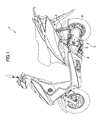
- Fig. 1 is a side view of a vehicle 1 equipped with a belt-type electronically-controlled continuously variable transmission 5 according to an embodiment of the invention.
- the vehicle 1 is a so-called scooter-type motorcycle.
- a vehicle to which the invention is applied is not limited to a scooter, and any vehicle may be used as long as the vehicle adopts a belt-type electronically-controlled continuously variable transmission according to the invention.
- a vehicle to which a belt-type electronically-controlled continuously variable transmission is preferably adopted is a relatively small and lightweight vehicle having simple structure.
- An example of such a vehicle includes a saddle type vehicle, for example.
- the saddle type vehicle is a motor vehicle having a saddle astride which an occupant sits.
- the saddle type vehicle includes a motorcycle, a motor tricycle, a three- or four-wheeled buggy, which is so-called All Terrain Vehicle (ATV), and snow mobile.
- ATV All Terrain Vehicle
- the belt-type electronically-controlled continuously variable transmission is usually applied to a so-called underbone type motorcycle, such as a scooter or moped type vehicle, having a swing unit.
- the type of vehicle is not limited thereto.
- the vehicle to which the invention is adopted includes a saddle type vehicle, and the saddle type vehicle includes a motorcycle.
- the motorcycle includes an underbone type one.
- the vehicle 1 includes a swing unit 3 which is rotatably joined to a main body frame of the vehicle 1 and swingably supported, by a suspension 2, with respect to a main body of the vehicle 1.
- An engine 4 the belt-type electronically-controlled continuously variable transmission 5, and a rear wheel 6 are provided in the swing unit 3, and these members integrally swing as the swing unit 3.
- the belt-type electronically-controlled continuously variable transmission described in this specification is a belt-type continuously variable transmission in which a gear ratio is changed in accordance with a command from a certain electronic control equipment, such as an electronic control unit (an ECU).
- a transmission using a general V-belt is preferable as a belt-type transmission.
- other types of transmissions may also be available.
- Fig. 2 is a horizontal partial cross-sectional view of a surface including an input shaft 50 of the belt-type electronically-controlled continuously variable transmission 5. Furthermore, a cross-section of the engine 4 is schematically illustrated in the same drawing.
- a crank shaft 40 of the engine 4 extends to a left side in terms of drawings and is the input shaft 50 of the belt-type electronically-controlled continuously variable transmission 5, and the crank shaft 40 is integrally directly connected to the input shaft 50.
- the crank shaft 40 and the input shaft 50 may be separately configured and both shafts may be joined via a proper coupling.
- a primary pulley 51 is mounted on the input shaft 50.
- the primary pulley 51 is constituted by a fixing sheave 52 and a movable sheave 53, which are a pair of opposing sheaves.
- the fixing sheave 52 is non-movably fixed to the input shaft 50 and rotates integrally with the input shaft 50.
- the movable sheave 53 is mounted on the input shaft 50 via a spline mechanism.
- Rotational movement of the movable sheave 53 is restricted with respect to the input shaft 50, but axial movement thereof is possible.
- facing surfaces of the fixing sheave 52 and the movable sheave 53 are inclined such that a gap between the inclined surfaces is gradually increased as the surfaces move radially outward.
- a V-belt 54 is wound between the inclined surfaces.
- the movable sheave 53 is provided in a crank shaft 40 side and the fixing sheave 52 is provided in the opposite side of the crank shaft 40.
- the terms "pulley” and “sheave” are separated as follows. The “pulley” indicates a wheel itself around which a belt is wound, and the “sheave” indicates a circular plate which constitutes the pulley.
- a sheave drive mechanism 7 to axially drive the movable sheave 53 is provided in a space located on a side opposite the inclined surface of the movable sheave 53. Detail of the sheave drive mechanism 7 will be described below.
- a slider 70, a worm wheel 71, a worm gear 72, a pulsar ring 73, a pickup 74, and the like which constitute the sheave drive mechanism 7 are illustrated in Fig. 2 .
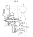
- Fig. 3 is a horizontal partial cross-sectional view of a surface including an output shaft 55 of the belt-type electronically-controlled continuously variable transmission 5. Furthermore, cross-sections of the rear wheel 6 and a clutch 56 are schematically illustrated in the same drawing.
- a secondary pulley 57 is mounted on the output shaft 55.
- the secondary pulley 57 is constituted by a fixing sheave 58 and a driven sheave 59, which are a pair of opposing sheaves.
- the fixing sheave 58 is fixed to a sleeve 60 having a cylindrical shape.
- the sleeve 60 is rotatably supported, via a bearing, to the output shaft 55 which passes through an inner side of the sleeve 60, and thus axial movement of the sleeve 60 is restricted.
- the fixing sheave 58 is rotatable with respect to the output shaft 55 and is fixed in the axis direction.
- the driven sheave 59 is mounted on the sleeve 60 via a spline mechanism. Thus, rotational movement of the driven sheave 59 is restricted with respect to the sleeve 60 and axial movement thereof is possible.
- facing surfaces of the fixing sheave 58 and the driven sheave 59 are inclined such that a gap between the inclined surfaces is gradually increased as the surfaces move radially outward.
- the V-belt 54 is wound between the inclined surfaces.
- a compression spring 62 is disposed between a surface opposite the inclined surface of the driven sheave 59, and a pressing plate 61 fixed to an end portion of the sleeve 60. The compression spring 62 presses the driven sheave 59 against the fixing sheave 58.
- the clutch 56 is provided in the end portion of the sleeve 60.
- the sleeve 60 to which the clutch 56 is connected rotates integrally with the output shaft 55.
- the clutch 56 is connected, and thus the secondary pulley 57 and the output shaft 55 rotate at the same rotational speed.
- the output shaft 55 and the rear wheel 6 are connected via a proper final reduction mechanism 8.
- the gap between the fixing sheave 52 and the movable sheave 53 of the primary pulley 51 is defined in accordance with the positioning of the movable sheave 53 by the sheave drive mechanism 7.
- the farthest position state between the fixing sheave 52 and the movable sheave 53 is illustrated on an upper side of the input shaft 50
- the closest position state between the fixing sheave 52 and the movable sheave 53 is illustrated on a lower side of the input shaft 50.
- gyration radius of the V-belt 54 with respect to the primary pulley 51 is defined corresponding to the gap between the fixing sheave 52 and the movable sheave 53.
- the driven sheave 59 is pressed to the fixing sheave 58 by a pressing force of the compression spring 62, regardless of the position of the movable sheave 53 of the primary pulley 51.
- the V-belt 54 is wound, without loosening, between the primary pulley 51 and the secondary pulley 57. Therefore, the gap between the fixing sheave 58 and the driven sheave 59 of the secondary pulley 57 is defined corresponding to the position of the movable sheave 53 in the primary pulley 51.
- the farthest position state between the fixing sheave 58 and the driven sheave 59 is illustrated on an upper side of the output shaft 55
- the closest position state between the fixing sheave 58 and the driven sheave 59 is illustrated on a lower side of the output shaft 55.
- gyration radius of the V-belt 54 with respect to the secondary pulley 57 is defined corresponding to the gap between the fixing sheave 58 and the driven sheave 59.
- the belt-type electronically-controlled continuously variable transmission 5 changes gyration radius of the V-belt 54 with respect to the primary pulley 51 and gyration radius of the V-belt 54 with respect to the secondary pulley 57 by causing the sheave drive mechanism 7 to vary the axial position of the movable sheave 53 to the input shaft 50.
- a gear ratio that is, the rotational speed ratio of the output shaft 55 to the input shaft 50, is continuously controlled.
- Fig. 4 is a partially enlarged cross-sectional view illustrating structures of the movable sheave 53 and the sheave drive mechanism 7.
- the movable sheave 53 is constituted by a flange portion 53a which has a circular plate shape and has an inclined surface in contact with the V-belt 54 (see Fig. 2 ) and a cylindrical portion 53b which axially extends from an inner circumferential portion of the flange portion 53a to a side opposite the inclined surface.
- the cylindrical portion 53b covers a boss 63 to which the input shaft 50 is fitted.
- a slit 53c extending axially is provided on the cylindrical portion 53b and a pin 64 mounted in the boss 63 is inserted into the slit 53c.
- the boss 63 is axially and rotationally restricted with respect to the input shaft 50.
- These pin 64 and slit 53c constitute a spline mechanism.
- the specific configuration of the spline mechanism is not particularly limited and configuration other than those in the embodiment, such as a general type in which spline teeth are meshed with spline grooves, or a ball spline type may also be adopted.
- the slider 70 is a cylindrical-shaped member which is provided coaxially with the input shaft 50, therefore, the movable sheave 53.
- the outer diameter of the slider 70 is greater than the outer diameter of the cylindrical portion 53b.
- the inner circumferential surface of the slider 70 is connected to the outer circumferential surface of the cylindrical portion 53b via a bearing 75 as a connection portion.
- the slider 70 and the movable sheave 53 move integrally in the axis direction and are relatively freely rotatable in the rotation direction.
- a pin 70a is press-fitted to the slider 70 and inserted into a groove 65a which has a semi-cylindrical shape and is provided in a housing 65 of the belt-type electronically-controlled continuously variable transmission 5.
- the pin 70a is axially slidable on the groove 65a, and thus the axial movement of the slider 70 is possible with respect to the housing 65 and the rotational movement thereof is restricted.
- the pin 70a and the groove 65a also constitute a spline mechanism.
- the specific configuration of the spline mechanism is not particularly limited to the configurations in the embodiment, as similar to the above-described case.
- a male thread portion 70b is formed on the outer circumferential surface of the slider 70. Although a trapezoidal type thread is adopted as a type of the male thread portion 70b in the embodiment, an involute or other type of thread may also be adopted.
- the worm wheel 71 is a ring-shaped member which is provided coaxially with the input shaft 50, therefore, the movable sheave 53.
- the outer diameter of the worm wheel 71 is greater than the outer diameter of the slider 70.
- the male thread portion 70b formed on the outer circumferential surface of the slider 70 is screwed to a female thread portion 71a formed on the inner circumferential surface of the worm wheel 71.
- a helical gear 71b which is meshed with the worm gear 72 is formed on the outer circumferential surface of the worm wheel 71.
- the worm wheel 71 is mounted on the housing 65 via a bearing 76, and thus the axial movement of the worm wheel 71 is restricted with respect to the housing 65 and the rotational movement thereof is possible. Furthermore, the pulsar ring 73 which is a member having a ring shape is attached to the worm wheel 71. The pulsar ring 73 is a member which rotates integrally with the worm wheel 71. The pulsar ring 73 is provided to detect a rotation angle of the worm wheel 71 using the pickup 74. Further, a pair of the pulsar ring 73 and the pickup 74 constitute a rotation detection device for detecting a rotation angle of the worm wheel 71. This rotation detection device will be described below. However, in the rotation detection device, the pulsar ring 73 and the worm wheel 71 may not necessarily be formed separately, and the worm wheel 71 may integrally have a part functioning as the pulsar ring 73.
- the worm gear 72 is directly mounted on an output shaft of an electric motor, as described below.
- the pickup 74 is fixed to the housing 65 so as to face an outer circumferential surface of the pulsar ring 73.
- the pickup 74 can be located at any position as long as the pickup 74 faces the outer circumferential surface of the pulsar ring 73.
- the pickup 74 is not necessarily positioned within a cross-section including a rotation axis of the input shaft 50.
- the pickup 74 is illustrated in Fig. 4 to show the positional relationship between the pickup 74 and the pulsar ring 73.
- the slider 70 and the worm wheel 71 are arranged in a space on a side opposite the inclined surface of the flange portion 53a of the movable sheave 53.
- the connection portion that is, the axial position of the bearing 75, between the slider 70 and the cylindrical portion 53b of the movable sheave 53 is disposed to overlap the axial position of the male thread portion 70b by which the slider 70 is screwed to the worm wheel 71.
- Fig. 5 illustrates the sheave drive mechanism 7 when viewed from an axis direction.
- Fig. 5 shows Fig. 4 when viewed from a left side, and the flange portion 53a is not illustrated in Fig. 5 .
- the positional relationship between the worm gear 72 and the worm wheel 71 which are screwed to each other is illustrated in Fig. 5 .
- the position of an electric motor 77 for driving the worm gear 72 is illustrated in Fig. 5 .
- One side of the worm gear 72 is directly mounted on an output shaft of the electric motor 77 and the other side thereof is rotatably supported by a bearing 78.
- the worm gear 72 is arranged such that an axis direction thereof is arranged parallel to a tangential direction of the worm wheel 71.
- the electric motor 77 is similarly arranged such that an axis direction of the electric motor 77 is arranged parallel to the tangential direction of the worm wheel 71.
- an output shaft 77a thereof is coaxial with the worm gear 72.
- the worm gear 72 being "directly" mounted to the electric motor 77 means that a power transmission mechanism, such as a reduction gear, for changing a rotational speed is not interposed between the worm gear 72 and the electric motor 77. Therefore, there is no problem even when the worm gear 72 and the output shaft 77a of the electric motor 77 are connected using a proper flexible coupling.
- the number of components which constitute the sheave drive mechanism 7 having a structure described above is smaller than the number of components of the known mechanism for driving a movable sheave. Accordingly, the entire belt-type electronically-controlled continuously variable transmission 5 can be reduced in cost and reduced in the number of components.
- the worm gear 72 it is preferable that the worm gear 72 have a twisting angle smaller than a repose angle. This prevents power transmission from the worm wheel 71 to the worm gear 72, and thus the worm wheel 71 is in a so-called self lock state. Therefore, it is not necessary to install a break in the electric motor 77. Accordingly, a reduction in cost, a reduction in size (a compact size), and electric power saving which is because an electromagnetic brake is not necessary are realized. Furthermore, in a case where the worm wheel 71 is unable to be in a self lock state due to various reasons, a proper brake may be installed so as to prevent the worm wheel 71 from rotating when the electric motor 77 is not driven.
- the pulsar ring 73 of the embodiment has a concave-convex portions structure in which a plurality of convex portions 73a and concave portions 73b are periodically provided in an outer circumferential surface thereof, as illustrated in the drawing.
- the pulsar ring 73 is formed of a ferromagnetic material such as iron.
- the rotation of the pulsar ring 73 means that the electric motor 77 is in a driven state. Therefore, a rotation direction of the pulsar ring 73 can be determined by a driving direction of the electric motor 77.
- a part in which the concave-convex structure is formed non-periodically is formed on a part of the outer circumferential surface of the pulsar ring 73, in terms of the circumferential direction.
- this non-periodic structure is a flat portion 73c in which both the convex portions 73a and the concave portions 73b are not formed.
- the position of the flat portion 73c can be detected using the fact that a signal detected by the pickup 74 does not change despite the driving of the electric motor 77.
- An initial position of the worm wheel 71 is detected by detecting the flat portion 73c, and thus it is possible to return the worm wheel 71 to the initial position when power of the vehicle 1 is turned on, for example.
- the flat portion 73c is an example of the non-periodic structure and other configurations can be applied.
- the lead of the thread by which the worm wheel 71 is screwed to the slider 70 be a lead which enables the movable sheave 53 to move over the entire movable range thereof without causing one or more rotations of the worm wheel 71 (see Fig. 4 ).
- the movement amount of the movable sheave 53 by detecting, using the pickup 74, the rotation angle of a part of the pulsar ring 73, in which the concave-convex structure is formed periodically.
- the pulsar ring 73 of the embodiment is described as a ferromagnetic member in which the physical concave-convex structure is formed on the outer circumference thereof.
- it may be a circular ring of which an outer circumference is periodically magnetized, for example.
- the pickup 74 is a pickup which detects the rotation angle of the pulsar ring 73 by detecting a change in a magnetic field using a hall element, for example.
- the housing 65 illustrated in Fig. 5 is one of components constituting the housing 65 of the belt-type electronically-controlled continuously variable transmission 5. Further, the housing 65 illustrated in Fig. 5 is a part of the components.
- Figs. 6 to 11 are views illustrating various positional relationships between the housing 65, the rear wheel 6, and the sheave drive mechanism 7, when viewed from a side.
- a proper cross-section of the housing 65 is illustrated in Figs. 6 to 11 .
- some members, such as the secondary pulley, or V-belt, are not illustrated.
- the electric motor 77 of the sheave drive mechanism 7 is arranged such that the axis line thereof is parallel to a horizontal direction. Furthermore, the electric motor 77 is arranged below a horizontal plane including the rotation axis of the movable sheave 53. In addition, the electric motor 77 is arranged behind a vertical plane including the rotation axis of the movable sheave 53.
- the worm gear 72 is located below the belt-type electronically-controlled continuously variable transmission 5, and thus there is an advantage in that it is easy to lubricate the worm gear 72 by providing a proper oil pan or using the housing 65 itself as an oil pan. Furthermore, the electric motor 77 is disposed substantially between the primary pulley and the secondary pulley, and thus the entire belt-type electronically-controlled continuously variable transmission 5 is reduced in size.
- the electric motor 77 of the sheave drive mechanism 7 is arranged such that the axis line thereof is inclined from the horizontal plane at a certain angle. Furthermore, the electric motor 77 is arranged behind a vertical plane including the rotation axis of the movable sheave 53. In the illustrated example, the inclination angle of the axis line of the electric motor 77 is 45 degrees, but it is preferable that the inclination angle thereof is set to be in the range of between 30 degrees and 60 degrees. In this arrangement, both the worm gear 72 and the electric motor 77 are substantially accommodated in a space between the primary pulley and the secondary pulley.
- the entire belt-type electronically-controlled continuously variable transmission 5 is extremely reduced in size, and the appearance of the belt-type electronically-controlled continuously variable transmission 5 is substantially the same as the appearance of the belt-type continuously variable transmission in which the sheave drive mechanism 7 is not provided.
- the position of the worm gear 72 is low, and thus it is easy to lubricate the worm gear 72.
- the electric motor 77 of the sheave drive mechanism 7 is arranged such that the axis line thereof is parallel to a vertical direction. Furthermore, the electric motor 77 is arranged above the horizontal plane including the rotation axis of the movable sheave 53. In addition, the electric motor 77 is arranged behind the vertical plane including the rotation axis of the movable sheave 53. In this arrangement, the position of the electric motor 77 is high, and thus it is possible to prevent the electric motor 77 from being contaminated owing to a contact between the electric motor 77 and foreign objects, such as bounced stones during traveling, or a step of a road surface. In the Fig.
- the electric motor 77 of the sheave drive mechanism 7 is arranged such that the axis line thereof is parallel to a vertical direction. Furthermore, the electric motor 77 is arranged above the horizontal plane including the rotation axis of the movable sheave 53. In addition, the electric motor 77 is arranged ahead of the vertical plane including the rotation axis of the movable sheave 53. Furthermore, a part of the electric motor 77 is exposed to protrude to the outside of the housing 65. In this arrangement, wind directly hits the electric motor 77 during traveling, and thus it is advantageous to cool the electric motor 77. Also, it is advantageous to prevent the electric motor 77 from being contaminated, as similar to the example illustrated in Fig. 8 .
- the electric motor 77 protruding to the outside of the housing 65 does not mean that the electric motor 77 is necessarily exposed without being covered with the housing 65. Even when the housing 65 is formed to cover the electric motor 77, the arrangement illustrated in Fig. 9 is still advantageous to cool the electric motor 77.
- the housing 65 is a case in which members constituting the belt-type electronically-controlled continuously variable transmission 5, such as the primary pulley, the secondary pulley, the V-belt, the slider, the worm wheel, and the worm gear are accommodated in addition to the electric motor 77
- a substantially convex shape enveloping the members is generally selected as a reasonable shape of the housing 65.
- the outside of the housing 65 means an area outside the housing 65, in terms of the reasonable-shaped housing 65 as a case having the members, in addition to the electric motor 77, accommodated therein. Furthermore, in this arrangement, the electric motor 77 and the rear wheel 6 also do not overlap when viewed from a side.
- the electric motor 77 of the sheave drive mechanism 7 is arranged such that the axis line thereof is parallel to the horizontal direction. Furthermore, the electric motor 77 is arranged below the horizontal plane including the rotation axis of the movable sheave 53. In addition, the electric motor 77 is arranged ahead of the vertical plane including the rotation axis of the movable sheave 53. Furthermore, a part of the electric motor 77 is exposed to protrude to the outside of the housing 65. In this arrangement, it is advantageous to lubricate the worm gear 72, as similar to the case illustrated in Fig. 6 . Also, wind directly hits the electric motor 77 during traveling, and thus it is advantageous to cool the electric motor 77. In addition, in this arrangement, the electric motor 77 and the rear wheel 6 also do not overlap when viewed from a side.
- the electric motor 77 of the sheave drive mechanism 7 is arranged such that the axis line thereof is parallel to the horizontal direction. Furthermore, the electric motor 77 is arranged above the horizontal plane including the rotation axis of the movable sheave 53. In addition, the electric motor 77 is arranged behind the vertical plane including the rotation axis of the movable sheave 53. Furthermore, in this arrangement, the electric motor 77 is disposed substantially between the primary pulley and the secondary pulley, as similar to the case illustrated in Fig. 6 , and thus the entire belt-type electronically-controlled continuously variable transmission 5 is reduced in size. In addition, it is advantageous to prevent the electric motor 77 from being contaminated, as similar to the case illustrated in Fig. 8 .
Landscapes
- Engineering & Computer Science (AREA)
- General Engineering & Computer Science (AREA)
- Mechanical Engineering (AREA)
- Transmissions By Endless Flexible Members (AREA)
- Gear Transmission (AREA)
Claims (10)
- Transmission variable continue à commande électronique de type courroie (5), comprenant:un boîtier (65);une poulie primaire (51) présentant un réa mobile (53);une poulie secondaire (57) présentant un réa entraîné (59);une courroie (54) qui est enroulée entre la poulie primaire (51) et la poulie secondaire (57);un patin (70) qui est prévu de manière coaxiale au réa mobile (53) et qui est connecté de manière à être déplaçable axialement et non déplaçable en rotation par rapport au boîtier (65) par l'intermédiaire d'un mécanisme à cannelures (65a, 70a) qui est prévu d'un côté intérieur du patin (70) et à être non déplaçable axialement et déplaçable en rotation par rapport au réa mobile (53);une roue hélicoïdale (71) qui est prévue coaxiale au réa mobile (53) et vissé sur le patin (70) à l'aide d'un filet;un engrenage hélicoïdal (72) dont une direction d'axe est une direction tangentielle de la roue hélicoïdale (71) et qui est vissé sur la roue hélicoïdale (71); etun moteur électrique (77) présentant l'engrenage hélicoïdal (72) monté sur un arbre de sortie (77a) de ce dernier.
- Transmission variable continue à commande électronique de type courroie (5) selon la revendication 1,
dans laquelle une partie de connexion qui est connectée au réa mobile (53) est prévue sur une surface circonférentielle intérieure du patin (70) et une partie de filet mâle (70b) qui est vissée sur la roue hélicoïdale (71) est prévue sur une surface circonférentielle extérieure de cette dernière, et
dans laquelle une partie de filet femelle (71a) sur laquelle est vissé le patin (70) est prévue sur une surface circonférentielle intérieure de la roue hélicoïdale (71). - Transmission variable continue à commande électronique de type courroie (5) selon la revendication 1 ou 2, comprenant par ailleurs:un dispositif de détection de rotation qui comporteune bague Pulsar (73) qui est fixée à la roue hélicoïdale (71), etun capteur (74) qui est prévu de manière à faire face à une surface circonférentielle extérieure de la bague Pulsar (73) et qui détecte la rotation de la bague Pulsar (73).
- Transmission variable continue à commande électronique de type courroie (5) selon la revendication 3,
dans laquelle une structure concave-convexe est prévue sur un bord circonférentiel extérieur de la bague Pulsar (73), et au moins une partie de la structure concave-convexe dans une direction circonférentielle est formée de manière non périodique. - Véhicule (1) équipé de la transmission variable continue à commande électronique de type courroie (5) selon l'une quelconque des revendications 1 à 4.
- Véhicule (1) selon la revendication 5,
dans lequel le moteur électrique (77) est disposé au-dessous d'un plan horizontal comportant un axe de rotation du réa mobile (53). - Véhicule (1) selon la revendication 5,
dans lequel le moteur électrique (77) est disposé au-dessus du plan horizontal comportant l'axe de rotation du réa mobile (53). - Véhicule (1) selon la revendication 5,
dans lequel le moteur électrique (77) est disposé dans le véhicule (1) de manière à se situer à l'avant d'un plan vertical comportant l'axe de rotation du réa mobile (53) et fait saillie à l'extérieur du boîtier (65). - Véhicule (1) selon l'une quelconque des revendications 5 à 8, dans lequel le moteur électrique (77) est disposé en une position à laquelle le moteur électrique (77) et une roue d'entraînement (6) du véhicule (1) ne se chevauchent pas, lorsque vu d'un côté.
- Véhicule (1) selon l'une quelconque des revendications 1 à 9, dans lequel la roue hélicoïdale (71) est montée sur le boîtier (65) par l'intermédiaire d'un roulement (76).
Applications Claiming Priority (1)
| Application Number | Priority Date | Filing Date | Title |
|---|---|---|---|
| JP2013021748A JP2014152832A (ja) | 2013-02-06 | 2013-02-06 | ベルト式電子制御無段変速機及びベルト式電子制御無段変速機を備えた車両 |
Publications (2)
| Publication Number | Publication Date |
|---|---|
| EP2765337A1 EP2765337A1 (fr) | 2014-08-13 |
| EP2765337B1 true EP2765337B1 (fr) | 2015-09-16 |
Family
ID=50031211
Family Applications (1)
| Application Number | Title | Priority Date | Filing Date |
|---|---|---|---|
| EP14153684.7A Active EP2765337B1 (fr) | 2013-02-06 | 2014-02-03 | Transmission variable continue à commande électronique de type courroie et véhicule équipé de celle-ci |
Country Status (3)
| Country | Link |
|---|---|
| EP (1) | EP2765337B1 (fr) |
| JP (1) | JP2014152832A (fr) |
| ES (1) | ES2555677T3 (fr) |
Families Citing this family (1)
| Publication number | Priority date | Publication date | Assignee | Title |
|---|---|---|---|---|
| IT201800009928A1 (it) | 2018-10-30 | 2020-04-30 | Piaggio & C Spa | Gruppo di trasmissione per motoveicoli con retromarcia e motoveicolo comprendente il gruppo di trasmissione |
Family Cites Families (7)
| Publication number | Priority date | Publication date | Assignee | Title |
|---|---|---|---|---|
| GB1011870A (en) * | 1961-05-26 | 1965-12-01 | Ulrich Schaufler | An improved infinitely variable belt transmission |
| US4909776A (en) * | 1987-08-28 | 1990-03-20 | Aisin Aw Co., Ltd. | Continuously variable transmission |
| JP2548258B2 (ja) | 1987-12-26 | 1996-10-30 | アイシン・エィ・ダブリュ株式会社 | ベルト式無段変速装置 |
| JP3194641B2 (ja) | 1993-02-24 | 2001-07-30 | 本田技研工業株式会社 | 車両用無段変速制御装置 |
| JP4380847B2 (ja) * | 1999-07-21 | 2009-12-09 | 東京自動機工株式会社 | 伝動機の伝達体加圧制御装置 |
| JP4067769B2 (ja) * | 2001-01-15 | 2008-03-26 | 本田技研工業株式会社 | ベルト式自動変速機のベルト交換時期報知装置 |
| TWI456126B (zh) * | 2010-10-25 | 2014-10-11 | Ind Tech Res Inst | 電控皮帶式無段變速系統 |
-
2013
- 2013-02-06 JP JP2013021748A patent/JP2014152832A/ja active Pending
-
2014
- 2014-02-03 EP EP14153684.7A patent/EP2765337B1/fr active Active
- 2014-02-03 ES ES14153684.7T patent/ES2555677T3/es active Active
Also Published As
| Publication number | Publication date |
|---|---|
| JP2014152832A (ja) | 2014-08-25 |
| EP2765337A1 (fr) | 2014-08-13 |
| ES2555677T3 (es) | 2016-01-07 |
Similar Documents
| Publication | Publication Date | Title |
|---|---|---|
| US6733406B2 (en) | Variable-speed V-belt drive for vehicle | |
| CN101258390B (zh) | 旋转检测器和扭矩检测器 | |
| US20230279937A1 (en) | Continuously variable transmission for recreational vehicles and related components | |
| US20080312013A1 (en) | Belt Continuously Variable Transmission for Straddle Type Vehicle, and Straddle Type Vehicle | |
| EP2784358B1 (fr) | Transmission variable continue à courroie en V | |
| JP2011021665A (ja) | ベルト式無段変速機 | |
| EP2765337B1 (fr) | Transmission variable continue à commande électronique de type courroie et véhicule équipé de celle-ci | |
| JP6461468B2 (ja) | Vベルト式無段変速機 | |
| WO2014132749A1 (fr) | Transmission continue de type à courroie en v | |
| JP7500182B2 (ja) | 無段変速機 | |
| CN102518763B (zh) | 用于跨乘式车辆的带式无级变速器和跨乘式车辆 | |
| TWI732907B (zh) | 無段變速器 | |
| US20080102998A1 (en) | Nonrotational torque sensing belt drive | |
| JP2015007462A (ja) | Vベルト式無段変速機 | |
| CN110382926A (zh) | 高性能同步传动装置 | |
| JP2006064172A (ja) | Vベルト式無段変速機 | |
| JP6176060B2 (ja) | 電動アクチュエータ | |
| JP2025158491A (ja) | 無段変速機、及び、無段変速機を有する鞍乗型車両 | |
| JP7822413B2 (ja) | プーリ装置、無段変速機および車両 | |
| JP2025158456A (ja) | 無段変速機、及び無段変速機を備える鞍乗型車両 | |
| JP2011179567A (ja) | ベルト式無段変速装置 | |
| EP2402244B1 (fr) | Structure de connexion de bras arrière de motocyclette | |
| JP2006029504A (ja) | 小型車両用のvベルト式無段変速機 | |
| JP2025158457A (ja) | エンジンユニット、及びエンジンユニットを備える鞍乗型車両 | |
| CN110366652A (zh) | 高性能同步传动装置 |
Legal Events
| Date | Code | Title | Description |
|---|---|---|---|
| PUAI | Public reference made under article 153(3) epc to a published international application that has entered the european phase |
Free format text: ORIGINAL CODE: 0009012 |
|
| 17P | Request for examination filed |
Effective date: 20140203 |
|
| AK | Designated contracting states |
Kind code of ref document: A1 Designated state(s): AL AT BE BG CH CY CZ DE DK EE ES FI FR GB GR HR HU IE IS IT LI LT LU LV MC MK MT NL NO PL PT RO RS SE SI SK SM TR |
|
| AX | Request for extension of the european patent |
Extension state: BA ME |
|
| REG | Reference to a national code |
Ref country code: DE Ref legal event code: R079 Ref document number: 602014000223 Country of ref document: DE Free format text: PREVIOUS MAIN CLASS: F16H0061662000 Ipc: F16H0063060000 |
|
| R17P | Request for examination filed (corrected) |
Effective date: 20150203 |
|
| RBV | Designated contracting states (corrected) |
Designated state(s): AL AT BE BG CH CY CZ DE DK EE ES FI FR GB GR HR HU IE IS IT LI LT LU LV MC MK MT NL NO PL PT RO RS SE SI SK SM TR |
|
| GRAP | Despatch of communication of intention to grant a patent |
Free format text: ORIGINAL CODE: EPIDOSNIGR1 |
|
| RIC1 | Information provided on ipc code assigned before grant |
Ipc: F16H 9/18 20060101ALI20150309BHEP Ipc: F16H 63/06 20060101AFI20150309BHEP |
|
| INTG | Intention to grant announced |
Effective date: 20150331 |
|
| GRAS | Grant fee paid |
Free format text: ORIGINAL CODE: EPIDOSNIGR3 |
|
| GRAA | (expected) grant |
Free format text: ORIGINAL CODE: 0009210 |
|
| AK | Designated contracting states |
Kind code of ref document: B1 Designated state(s): AL AT BE BG CH CY CZ DE DK EE ES FI FR GB GR HR HU IE IS IT LI LT LU LV MC MK MT NL NO PL PT RO RS SE SI SK SM TR |
|
| REG | Reference to a national code |
Ref country code: GB Ref legal event code: FG4D |
|
| REG | Reference to a national code |
Ref country code: CH Ref legal event code: EP |
|
| REG | Reference to a national code |
Ref country code: IE Ref legal event code: FG4D |
|
| REG | Reference to a national code |
Ref country code: AT Ref legal event code: REF Ref document number: 750081 Country of ref document: AT Kind code of ref document: T Effective date: 20151015 |
|
| REG | Reference to a national code |
Ref country code: DE Ref legal event code: R096 Ref document number: 602014000223 Country of ref document: DE |
|
| REG | Reference to a national code |
Ref country code: ES Ref legal event code: FG2A Ref document number: 2555677 Country of ref document: ES Kind code of ref document: T3 Effective date: 20160107 |
|
| REG | Reference to a national code |
Ref country code: NL Ref legal event code: MP Effective date: 20150916 |
|
| PG25 | Lapsed in a contracting state [announced via postgrant information from national office to epo] |
Ref country code: GR Free format text: LAPSE BECAUSE OF FAILURE TO SUBMIT A TRANSLATION OF THE DESCRIPTION OR TO PAY THE FEE WITHIN THE PRESCRIBED TIME-LIMIT Effective date: 20151217 Ref country code: FI Free format text: LAPSE BECAUSE OF FAILURE TO SUBMIT A TRANSLATION OF THE DESCRIPTION OR TO PAY THE FEE WITHIN THE PRESCRIBED TIME-LIMIT Effective date: 20150916 Ref country code: LV Free format text: LAPSE BECAUSE OF FAILURE TO SUBMIT A TRANSLATION OF THE DESCRIPTION OR TO PAY THE FEE WITHIN THE PRESCRIBED TIME-LIMIT Effective date: 20150916 Ref country code: LT Free format text: LAPSE BECAUSE OF FAILURE TO SUBMIT A TRANSLATION OF THE DESCRIPTION OR TO PAY THE FEE WITHIN THE PRESCRIBED TIME-LIMIT Effective date: 20150916 Ref country code: NO Free format text: LAPSE BECAUSE OF FAILURE TO SUBMIT A TRANSLATION OF THE DESCRIPTION OR TO PAY THE FEE WITHIN THE PRESCRIBED TIME-LIMIT Effective date: 20151216 |
|
| REG | Reference to a national code |
Ref country code: LT Ref legal event code: MG4D |
|
| REG | Reference to a national code |
Ref country code: AT Ref legal event code: MK05 Ref document number: 750081 Country of ref document: AT Kind code of ref document: T Effective date: 20150916 |
|
| REG | Reference to a national code |
Ref country code: FR Ref legal event code: PLFP Year of fee payment: 3 |
|
| PG25 | Lapsed in a contracting state [announced via postgrant information from national office to epo] |
Ref country code: RS Free format text: LAPSE BECAUSE OF FAILURE TO SUBMIT A TRANSLATION OF THE DESCRIPTION OR TO PAY THE FEE WITHIN THE PRESCRIBED TIME-LIMIT Effective date: 20150916 Ref country code: SE Free format text: LAPSE BECAUSE OF FAILURE TO SUBMIT A TRANSLATION OF THE DESCRIPTION OR TO PAY THE FEE WITHIN THE PRESCRIBED TIME-LIMIT Effective date: 20150916 Ref country code: HR Free format text: LAPSE BECAUSE OF FAILURE TO SUBMIT A TRANSLATION OF THE DESCRIPTION OR TO PAY THE FEE WITHIN THE PRESCRIBED TIME-LIMIT Effective date: 20150916 |
|
| PG25 | Lapsed in a contracting state [announced via postgrant information from national office to epo] |
Ref country code: NL Free format text: LAPSE BECAUSE OF FAILURE TO SUBMIT A TRANSLATION OF THE DESCRIPTION OR TO PAY THE FEE WITHIN THE PRESCRIBED TIME-LIMIT Effective date: 20150916 |
|
| PG25 | Lapsed in a contracting state [announced via postgrant information from national office to epo] |
Ref country code: SK Free format text: LAPSE BECAUSE OF FAILURE TO SUBMIT A TRANSLATION OF THE DESCRIPTION OR TO PAY THE FEE WITHIN THE PRESCRIBED TIME-LIMIT Effective date: 20150916 Ref country code: IS Free format text: LAPSE BECAUSE OF FAILURE TO SUBMIT A TRANSLATION OF THE DESCRIPTION OR TO PAY THE FEE WITHIN THE PRESCRIBED TIME-LIMIT Effective date: 20160116 Ref country code: CZ Free format text: LAPSE BECAUSE OF FAILURE TO SUBMIT A TRANSLATION OF THE DESCRIPTION OR TO PAY THE FEE WITHIN THE PRESCRIBED TIME-LIMIT Effective date: 20150916 Ref country code: EE Free format text: LAPSE BECAUSE OF FAILURE TO SUBMIT A TRANSLATION OF THE DESCRIPTION OR TO PAY THE FEE WITHIN THE PRESCRIBED TIME-LIMIT Effective date: 20150916 |
|
| PG25 | Lapsed in a contracting state [announced via postgrant information from national office to epo] |
Ref country code: BE Free format text: LAPSE BECAUSE OF NON-PAYMENT OF DUE FEES Effective date: 20160229 Ref country code: AT Free format text: LAPSE BECAUSE OF FAILURE TO SUBMIT A TRANSLATION OF THE DESCRIPTION OR TO PAY THE FEE WITHIN THE PRESCRIBED TIME-LIMIT Effective date: 20150916 Ref country code: PT Free format text: LAPSE BECAUSE OF FAILURE TO SUBMIT A TRANSLATION OF THE DESCRIPTION OR TO PAY THE FEE WITHIN THE PRESCRIBED TIME-LIMIT Effective date: 20160118 Ref country code: PL Free format text: LAPSE BECAUSE OF FAILURE TO SUBMIT A TRANSLATION OF THE DESCRIPTION OR TO PAY THE FEE WITHIN THE PRESCRIBED TIME-LIMIT Effective date: 20150916 Ref country code: RO Free format text: LAPSE BECAUSE OF FAILURE TO SUBMIT A TRANSLATION OF THE DESCRIPTION OR TO PAY THE FEE WITHIN THE PRESCRIBED TIME-LIMIT Effective date: 20150916 |
|
| REG | Reference to a national code |
Ref country code: DE Ref legal event code: R097 Ref document number: 602014000223 Country of ref document: DE |
|
| PLBE | No opposition filed within time limit |
Free format text: ORIGINAL CODE: 0009261 |
|
| STAA | Information on the status of an ep patent application or granted ep patent |
Free format text: STATUS: NO OPPOSITION FILED WITHIN TIME LIMIT |
|
| 26N | No opposition filed |
Effective date: 20160617 |
|
| PG25 | Lapsed in a contracting state [announced via postgrant information from national office to epo] |
Ref country code: DK Free format text: LAPSE BECAUSE OF FAILURE TO SUBMIT A TRANSLATION OF THE DESCRIPTION OR TO PAY THE FEE WITHIN THE PRESCRIBED TIME-LIMIT Effective date: 20150916 |
|
| PG25 | Lapsed in a contracting state [announced via postgrant information from national office to epo] |
Ref country code: MC Free format text: LAPSE BECAUSE OF FAILURE TO SUBMIT A TRANSLATION OF THE DESCRIPTION OR TO PAY THE FEE WITHIN THE PRESCRIBED TIME-LIMIT Effective date: 20150916 Ref country code: LU Free format text: LAPSE BECAUSE OF FAILURE TO SUBMIT A TRANSLATION OF THE DESCRIPTION OR TO PAY THE FEE WITHIN THE PRESCRIBED TIME-LIMIT Effective date: 20160203 |
|
| PG25 | Lapsed in a contracting state [announced via postgrant information from national office to epo] |
Ref country code: SI Free format text: LAPSE BECAUSE OF FAILURE TO SUBMIT A TRANSLATION OF THE DESCRIPTION OR TO PAY THE FEE WITHIN THE PRESCRIBED TIME-LIMIT Effective date: 20150916 |
|
| REG | Reference to a national code |
Ref country code: IE Ref legal event code: MM4A |
|
| PG25 | Lapsed in a contracting state [announced via postgrant information from national office to epo] |
Ref country code: BE Free format text: LAPSE BECAUSE OF FAILURE TO SUBMIT A TRANSLATION OF THE DESCRIPTION OR TO PAY THE FEE WITHIN THE PRESCRIBED TIME-LIMIT Effective date: 20150916 |
|
| PG25 | Lapsed in a contracting state [announced via postgrant information from national office to epo] |
Ref country code: IE Free format text: LAPSE BECAUSE OF NON-PAYMENT OF DUE FEES Effective date: 20160203 |
|
| REG | Reference to a national code |
Ref country code: FR Ref legal event code: PLFP Year of fee payment: 4 |
|
| PG25 | Lapsed in a contracting state [announced via postgrant information from national office to epo] |
Ref country code: MT Free format text: LAPSE BECAUSE OF FAILURE TO SUBMIT A TRANSLATION OF THE DESCRIPTION OR TO PAY THE FEE WITHIN THE PRESCRIBED TIME-LIMIT Effective date: 20150916 |
|
| REG | Reference to a national code |
Ref country code: CH Ref legal event code: PL |
|
| PG25 | Lapsed in a contracting state [announced via postgrant information from national office to epo] |
Ref country code: LI Free format text: LAPSE BECAUSE OF NON-PAYMENT OF DUE FEES Effective date: 20170228 Ref country code: CH Free format text: LAPSE BECAUSE OF NON-PAYMENT OF DUE FEES Effective date: 20170228 |
|
| REG | Reference to a national code |
Ref country code: FR Ref legal event code: PLFP Year of fee payment: 5 |
|
| PG25 | Lapsed in a contracting state [announced via postgrant information from national office to epo] |
Ref country code: CY Free format text: LAPSE BECAUSE OF FAILURE TO SUBMIT A TRANSLATION OF THE DESCRIPTION OR TO PAY THE FEE WITHIN THE PRESCRIBED TIME-LIMIT Effective date: 20150916 Ref country code: HU Free format text: LAPSE BECAUSE OF FAILURE TO SUBMIT A TRANSLATION OF THE DESCRIPTION OR TO PAY THE FEE WITHIN THE PRESCRIBED TIME-LIMIT; INVALID AB INITIO Effective date: 20140203 Ref country code: SM Free format text: LAPSE BECAUSE OF FAILURE TO SUBMIT A TRANSLATION OF THE DESCRIPTION OR TO PAY THE FEE WITHIN THE PRESCRIBED TIME-LIMIT Effective date: 20150916 |
|
| PG25 | Lapsed in a contracting state [announced via postgrant information from national office to epo] |
Ref country code: MK Free format text: LAPSE BECAUSE OF FAILURE TO SUBMIT A TRANSLATION OF THE DESCRIPTION OR TO PAY THE FEE WITHIN THE PRESCRIBED TIME-LIMIT Effective date: 20150916 Ref country code: MT Free format text: LAPSE BECAUSE OF FAILURE TO SUBMIT A TRANSLATION OF THE DESCRIPTION OR TO PAY THE FEE WITHIN THE PRESCRIBED TIME-LIMIT Effective date: 20160229 |
|
| PG25 | Lapsed in a contracting state [announced via postgrant information from national office to epo] |
Ref country code: BG Free format text: LAPSE BECAUSE OF FAILURE TO SUBMIT A TRANSLATION OF THE DESCRIPTION OR TO PAY THE FEE WITHIN THE PRESCRIBED TIME-LIMIT Effective date: 20150916 |
|
| PG25 | Lapsed in a contracting state [announced via postgrant information from national office to epo] |
Ref country code: AL Free format text: LAPSE BECAUSE OF FAILURE TO SUBMIT A TRANSLATION OF THE DESCRIPTION OR TO PAY THE FEE WITHIN THE PRESCRIBED TIME-LIMIT Effective date: 20150916 |
|
| P01 | Opt-out of the competence of the unified patent court (upc) registered |
Effective date: 20230527 |
|
| PGFP | Annual fee paid to national office [announced via postgrant information from national office to epo] |
Ref country code: TR Payment date: 20240202 Year of fee payment: 11 |
|
| PGFP | Annual fee paid to national office [announced via postgrant information from national office to epo] |
Ref country code: ES Payment date: 20250331 Year of fee payment: 12 |
|
| PGFP | Annual fee paid to national office [announced via postgrant information from national office to epo] |
Ref country code: GB Payment date: 20260219 Year of fee payment: 13 |
|
| PGFP | Annual fee paid to national office [announced via postgrant information from national office to epo] |
Ref country code: DE Payment date: 20260218 Year of fee payment: 13 |
|
| PGFP | Annual fee paid to national office [announced via postgrant information from national office to epo] |
Ref country code: IT Payment date: 20260224 Year of fee payment: 13 |
|
| PGFP | Annual fee paid to national office [announced via postgrant information from national office to epo] |
Ref country code: FR Payment date: 20260218 Year of fee payment: 13 |