EP2765363B1 - Dispositif de chauffage de liquide à resistance électrique - Google Patents
Dispositif de chauffage de liquide à resistance électrique Download PDFInfo
- Publication number
- EP2765363B1 EP2765363B1 EP14165076.2A EP14165076A EP2765363B1 EP 2765363 B1 EP2765363 B1 EP 2765363B1 EP 14165076 A EP14165076 A EP 14165076A EP 2765363 B1 EP2765363 B1 EP 2765363B1
- Authority
- EP
- European Patent Office
- Prior art keywords
- liquid
- electrodes
- current
- power
- temperature
- Prior art date
- Legal status (The legal status is an assumption and is not a legal conclusion. Google has not performed a legal analysis and makes no representation as to the accuracy of the status listed.)
- Expired - Lifetime
Links
Images


Classifications
-
- F—MECHANICAL ENGINEERING; LIGHTING; HEATING; WEAPONS; BLASTING
- F24—HEATING; RANGES; VENTILATING
- F24H—FLUID HEATERS, e.g. WATER OR AIR HEATERS, HAVING HEAT-GENERATING MEANS, e.g. HEAT PUMPS, IN GENERAL
- F24H1/00—Water heaters, e.g. boilers, continuous-flow heaters or water-storage heaters
- F24H1/10—Continuous-flow heaters, i.e. heaters in which heat is generated only while the water is flowing, e.g. with direct contact of the water with the heating medium
-
- F—MECHANICAL ENGINEERING; LIGHTING; HEATING; WEAPONS; BLASTING
- F24—HEATING; RANGES; VENTILATING
- F24H—FLUID HEATERS, e.g. WATER OR AIR HEATERS, HAVING HEAT-GENERATING MEANS, e.g. HEAT PUMPS, IN GENERAL
- F24H1/00—Water heaters, e.g. boilers, continuous-flow heaters or water-storage heaters
- F24H1/10—Continuous-flow heaters, i.e. heaters in which heat is generated only while the water is flowing, e.g. with direct contact of the water with the heating medium
- F24H1/101—Continuous-flow heaters, i.e. heaters in which heat is generated only while the water is flowing, e.g. with direct contact of the water with the heating medium using electric energy supply
- F24H1/106—Continuous-flow heaters, i.e. heaters in which heat is generated only while the water is flowing, e.g. with direct contact of the water with the heating medium using electric energy supply with electrodes
-
- F—MECHANICAL ENGINEERING; LIGHTING; HEATING; WEAPONS; BLASTING
- F24—HEATING; RANGES; VENTILATING
- F24H—FLUID HEATERS, e.g. WATER OR AIR HEATERS, HAVING HEAT-GENERATING MEANS, e.g. HEAT PUMPS, IN GENERAL
- F24H1/00—Water heaters, e.g. boilers, continuous-flow heaters or water-storage heaters
- F24H1/18—Water-storage heaters
- F24H1/20—Water-storage heaters with immersed heating elements, e.g. electric elements or furnace tubes
-
- H—ELECTRICITY
- H05—ELECTRIC TECHNIQUES NOT OTHERWISE PROVIDED FOR
- H05B—ELECTRIC HEATING; ELECTRIC LIGHT SOURCES NOT OTHERWISE PROVIDED FOR; CIRCUIT ARRANGEMENTS FOR ELECTRIC LIGHT SOURCES, IN GENERAL
- H05B3/00—Ohmic-resistance heating
- H05B3/60—Heating arrangements wherein the heating current flows through granular powdered or fluid material, e.g. for salt-bath furnace, electrolytic heating
-
- H—ELECTRICITY
- H05—ELECTRIC TECHNIQUES NOT OTHERWISE PROVIDED FOR
- H05B—ELECTRIC HEATING; ELECTRIC LIGHT SOURCES NOT OTHERWISE PROVIDED FOR; CIRCUIT ARRANGEMENTS FOR ELECTRIC LIGHT SOURCES, IN GENERAL
- H05B7/00—Heating by electric discharge
- H05B7/02—Details
- H05B7/144—Power supplies specially adapted for heating by electric discharge; Automatic control of power, e.g. by positioning of electrodes
-
- H—ELECTRICITY
- H05—ELECTRIC TECHNIQUES NOT OTHERWISE PROVIDED FOR
- H05B—ELECTRIC HEATING; ELECTRIC LIGHT SOURCES NOT OTHERWISE PROVIDED FOR; CIRCUIT ARRANGEMENTS FOR ELECTRIC LIGHT SOURCES, IN GENERAL
- H05B2203/00—Aspects relating to Ohmic resistive heating covered by group H05B3/00
- H05B2203/021—Heaters specially adapted for heating liquids
Definitions
- This invention is directed towards an electrically powered tankless electrically conductive liquid heater that provides instant, on demand heating of the liquid.
- an electrically powered tankless liquid heating device includes, at a minimum, provision of the heated liquid on demand, regulation of the temperature of the heated liquid so as not to exceed a maximum temperature set point, operation below a maximum electrical current set-point, safety of operation, minimal disturbance to the power supply and low cost to manufacture.
- Prior art liquid heating devices have attempted to achieve these objectives, but have been only partially able to do so.
- a flow detection switch (which must carry the entire electrical current consumed by the heating elements) detects the condition of no water flow, thus preventing dry firing of the heating elements where there is insufficient water in the heating chamber.
- the thermostat is not thermally connected to the heating element and thus the thermostat does nothing to prevent overheating of the electric heating element.
- Other tankless water heaters using electric heating elements that suffer the same disadvantage and the mechanisms to address it are described in US Patents 5,216,743 issued to Seitz , 5,325,822 issued to Fernandez , 5,408,578 issued to Bolivar , 5,479,558 White, Jr.
- the primary mechanism in '743 is an automatic vapor release outlet to ensure that the temperature sensors sense liquid temperature. This mechanism clearly does not function after the heater has been drained for servicing or for periods of no use. In '822, liquid level sensors are used. However, these are only effective in one mounting orientation of the heater.
- '578 provides two ports between two heating chambers to ensure that water enters the two chambers more or less equally, thereby preventing that one of the heating elements in one of the chambers can overheat while the other is filling with water.
- a flow-sensing switch is also used to prevent application of power unless water flow is detected.
- a flow- sensing switch is generally expensive and not reliable.
- '558 uses the combination of a sophisticated flow detector and thermal sensors, one for regulating temperature, the other for sensing an over temperature condition.
- the flow detector uses a plunger that is constrained to move vertically, thus constraining the heater to installation in only one orientation. Besides, as described, it is subject to binding and getting stuck in one position, including possibly a position that indicates the existence of water flow when there is none.
- the predominant alternative to using heating elements to heat the liquid is to pass an electrical current through the liquid by passing it between two electrodes between which a voltage exists.
- the voltage is preferably an AC voltage so as to avoid electrolysis of the liquid.
- This method is known as direct electrical resistance (DER) heating.
- DER direct electrical resistance
- a DER liquid heater is disclosed in US patent 6,130,990 issued to Herrick et al for use in a beverage dispenser.
- the advantages of "rapid and efficient transfer of electrical energy into the water as thermal energy while reducing the energy loss associated with indirect heating methods" are disclosed.
- One of the disadvantages of the DER method is that the amount of electrical current drawn by the liquid between the electrodes, and therefore the amount of heat delivered to the liquid, is determined by the electrical conductivity of the liquid, a parameter that can vary quite widely, for example 10 to 1.
- One method of controlling the temperature contemplated in this patent is by varying the water flow rate. Another is by varying the electrical power delivered to the water, which would require varying the power supply voltage.
- a third involves mechanically adjusting the distance between the electrodes.
- US patent 6,640,048 issued Novotny et al discloses a DER liquid heater that provides another adjustment mechanism that addresses the wide range of liquid conductivities. It mechanically varies the area of the electrodes (and the effective distance between them) by adjustably interposing an electrically non-conducting current gating plate between the electrodes, thus adjusting the electrical conductance of the heating zone comprising the electrodes and the liquid between them.
- the mechanical adjustment involves the translation of motion across a liquid to air barrier, something that is difficult to achieve reliably and at low cost.
- DER liquid heaters must also address other difficulties that are in common with heaters utilizing resistance type electrical heating elements.
- An example of these is the use of a flow switch to control the application of power to the heater.
- Flow switches are generally characterized by a flow rate threshold, below which they do not indicate a flow, although a low flow may be present. This allows for unheated liquid to leave the heater at low flow rates (unlike conventional tank type heaters), and it tends to generate a delay between the time liquid flow is demanded and the time fully heated liquid is finally delivered thus creating a wastage of liquid.
- This together with the presence of orientation limitations, unreliable functioning and cost must be overcome in a tankless liquid heating device that meets the objectives cited above.
- the previously mentioned difficulties associated with latent heat management, the design and operation of temperature control loops, formation of deposits, and minimization of power supply variations and the corresponding light flicker must be overcome.
- a liquid heater according to the preamble of claim 1 is known from DE 100 00 101 A1 .
- Both liquid heaters comprise a plurality of electrodes defining channels between them. Since the electrodes have the same distance, the channels all have the same width.
- FIG. 1 shows essential elements of the present invention.
- a liquid heating chamber 1 is shown comprising a liquid inlet 2, a plurality of electrodes 4 (the electrode array), the electrodes defining a plurality of channels, the spaces between the electrodes, through each of which liquid flows from the liquid inlet 2 to the liquid outlet 3, the liquid being heated when it flows through the channels and a voltage is applied between electrodes.
- the liquid heating chamber is shown with a bottom but without a top so that the electrodes and the channels defined by them can more clearly be seen.
- the electrodes 4 are shown in Figure 1 as having a non-uniform or unequal spacing, which will be explained later.
- the electrodes 4 are connected via connections 5 to switch matrix 6 via which AC electrical power is communicated to the electrodes.
- the electrodes 4 are thin relative to the width of the channels.
- the electrodes 4 are thinner than the width of the narrowest channel. This minimizes the amount of latent heat that can be stored in the electrodes and provides some balancing of the heating in the heating chamber in that heat created in one channel can be communicated through the electrodes to adjacent channels.
- Figure 1 also shows some aspects that are exemplary and not to be construed as limiting.
- the electrodes are shown as planar and parallel. This is not a limit to the scope of the invention.
- the electrodes may be sections of cones of different radii coaxially located such that the required plurality of channels is formed (in this case the channels will also be conical) and be within the scope of the present invention.
- Any geometric configuration of electrically unconnected electrodes that defines a plurality of channels through each of which a liquid may be passed from the liquid inlet 2 to the liquid outlet 3 and which provides an electrically conductive path between the two endmost electrodes when an electrically conductive liquid is in the channels and the interposed electrodes are electrically unconnected is within the scope of the present invention.
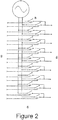
- FIG. 2 shows the details of the switch matrix 6 and its connections to power supply 7. Shown are two switches 8 for each connection 5 to the electrodes, one of the two switches connected to one side or phase of the AC power supply 7 and the other of the two switches connected to the second side or phase of the AC power supply 7.
- a multiple phase power supply be used with as many switches per connection 5 as exist phases of the power supply.
- All of the switches 8 are individually operable by their respective control signals 9.
- the switches 8 are any kind of electrically operable switch, i.e., a switch that utilizes an electrical input signal to operate the switch. Examples of suitable switches include relays and, more preferably, semiconductor switches such as triacs.
- the switches are selectively closed by a controller, thereby placing the power supply voltage between electrodes.
- the power delivered to heat the liquid between the electrodes is a function of 1) the spacing between the electrodes and 2) the number of electrode pairs to which power is applied through switches 8.
- the switch matrix 6 provides great flexibility in this regard. For example, when the minimum current is required, one of the switches 8 electrically connected to a first endmost electrode 4 (one of the two that define only one channel) is closed, thereby connecting the electrode to a first side of the power supply and one of the switches 8 electrically connected to the opposite endmost electrode (the electrode most distant from the first endmost electrode) is closed such that it is connected to a second side of the power supply.
- All of the other switches 8 remain open and therefore the electrodes 4 interposed between the endmost electrodes remain electrically unconnected. This places the maximum distance between the electrodes to which the voltage source can be connected, thereby causing the electrical conductance between the cells to be minimized and likewise the electrical current and therefore the power delivered to the liquid for heating to be likewise minimized. It is possible to increase the electrical current by connecting the power supply to an electrode via one of the switches 8 that is physically and closer to the first electrode.
- the present invention provides for adjusting the current, and power delivered for heating, according to the separation between the electrodes to which voltage is applied.
- switch positions or switch configurations there are a large number of possible combinations of switch positions or switch configurations, i.e., 2 raised to the power of the number of switches. It is also apparent that some of these switch configurations are not useful. For example, it not useful to close a switch connected to an electrode that causes it to be connected to the same side of the power supply that electrodes on both sides of it are connected to, as this performs no useful function because there is no electrical field generated between the electrodes and therefore no current will flow through the switch connected electrode. Additionally, it is not useful to simultaneously close two switches connected to the same electrode as this will simply short the power supply. Switches are also relatively expensive components, so it is desirable to minimize their number. Therefore, it is desirable to minimize the number of switches and switch combinations used.
- switch matrix 6 there is one switch per electrode, the switches connecting the electrodes to different terminals of the power supply in a round robin pattern, or if there are only two power supply terminals, in an alternating pattern.
- Comprising switch matrix 6 with one switch per electrode can normally provide an adequate number of switch configurations and corresponding current levels. However, there may be situations where the increase in the number of switch configurations is sufficiently worthwhile to justify more fully or fully populating the switch matrix 6 with more or all of the possible number of switches for making electrical connection between the electrodes and the power supply.
- Utilization of non-uniformly spaced electrodes according to the invention overcomes this difficulty.
- selection of the spacing between electrodes is such that a selection of switch matrix 6 configurations that yield more or less logarithmically uniformly spaced current steps can be achieved.
- An example of such spacings is discussed later in the description of a preferred embodiment of the invention.
- the inventors do not know of any method by which the optimum electrode spacings can be analytically calculated and are therefore unable to present such a method. Suitable electrode spacings were "discovered” using a genetic optimization algorithm that had as its objective to minimize the ratio of currents of the largest current step. Other methods for determining an adequate set of electrode spacings also exist.
- the electrically operable switches preferably comprise semiconductor switches and most preferably comprise triacs. Given their number, it is likely that the cost of the triacs will comprise a significant portion of the parts cost of the liquid heater. The cost of triacs is related to the maximum current that they can handle: higher current capacity triacs cost more. It is therefore desirable to minimize the maximum current requirements for the triacs.
- the inventors have found that just optimizing the electrode spacing for current step size does not automatically yield a set of electrode spacings that also yields the lowest maximum triac current. However, the inventors have discovered that, using the same genetic optimization algorithm, by adding the additional objective of a maximum triac current, it is possible to generate electrode spacings that simultaneously satisfy the current step size requirements and the maximum triac current requirements.
- a maximum triac current requirement (so that the lowest cost triac may be used) and current step size requirements are simultaneously satisfied by selection of the electrode spacings.
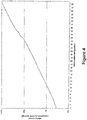
- Figure 4 shows the relative currents achieved from a selection of switch configurations with an optimized set of electrode spacings. With these spacings, the constraint of a maximum triac current has been achieved, the range of currents provided is 308 to 1, and the average current step ratio is approximately 1.10 and the maximum current step ratio is 1.22.
- the current control range and the step sizes are more than adequate to closely control the temperature of the heated liquid without causing excessive power supply load changes and corresponding light flickering.
- the electrode spacings make possible the operation of the liquid heater at a current that is quite close (5% nominally, 10% worst case) to a current set-point, the current set-point being the maximum current that the liquid heater can draw, without having to rapidly switch between quite different current levels (in order to achieve the set-point current by averaging) and thereby cause the aforementioned light flickering.
- the DER heater of this example was designed to heat water with conductivities of 200[mu]S/cm to 1500[mu]S/cm at flow rates of 0.6 gallons (2.3 liters) per minute to 2.5 gallons (9.5 liters) per minute and operate from a 220V AC power supply. It was a standard point of use water heater for domestic applications. It comprised 17 electrodes that were 0.9mm thick by 340mm long. The channel height, i.e., the height of the electrodes exposed to the liquid (which may be less than the actual physical height of the electrodes in order to accommodate mounting of them) was 8.6mm.
- the electrode array comprised sequentially numbered electrodes having the following interelectrode spacings:
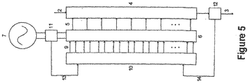
- a current measurement device 11 is made part of the liquid heater.
- AC power 7 is communicated to switch matrix 6 via current measurement device 11.
- a current signal 13, indicative of the current measured by the current measurement device 11, is communicated to the controller 10.
- the current measurement device 11 and the current signal 13 are used by the controller 10 to respond to the measured current by adjusting switch matrix 6 configuration such that the measured current does not exceed the current set-point. In this way, the maximum current drawn by the DER liquid heater can be controlled, independently of the liquid conductivity or temperature.
- a temperature-sensing element 12 is disposed at the end of the heating chamber, prior to outlet 3, and generates a temperature signal 14 indicative of the heated liquid temperature.
- the heated liquid temperature signal 14 is communicated to controller 10 which responds to it by adjusting the configuration of switch matrix 6 such that the water temperature is maintained as close as possible to a temperature set-point, but which, in any case, does not exceed it.
- the matrix switch configuration is always set such that current set- point takes priority over the temperature set-point. In other words, regardless of the demand for power to heat the liquid to the temperature set-point, the controller prevents drawing more current from the AC power supply 7 than the current set-point.
- the switch matrix comprised triacs, one per electrode, connected to the power supply in alternating fashion, i.e., adjacent electrodes were connected to opposite terminals of a two terminal power supply.
- the controller comprised a counter to control the power level, in other words, a power level counter, the value of which determined the power level to be applied to the electrodes 4 via the switch matrix 6.
- the operation of the power level counter was according to the following algorithm that was executed once every cycle of the power supply waveform:
- the counter had a range of values corresponding to power levels between zero power and a maximum power level.
- the algorithm also incorporated a mechanism to ensure that the operating range of the counter was not exceeded.
- the values of the counter are converted to switch matrix control signals 9 by any suitable means.
- the following look-up table was used: power level SW17 SW16 SW15 SW14 SW13 SW12 SW15 SW10 SW9 SW8 SW7 SW6 SW5 SW4 SW3 SW2 SW1 0 0 0 0 0 0 0 0 0 0 0 0 0 0 0 0 0 1 1 0 0 0 0 0 0 0 0 0 0 0 0 0 0 0 0 0 1 0 2 0 1 0 0 0 0 0 0 0 0 0 0 0 0 0 0 1 0 0 3 0 0 0 1 0 0 0 0 0 0 0 0 0 0 0 0 1 4 1 0 0 0 0 0 0 0 0 0 0 0 0 0 0 0 1 0 0 0 0 0 0
- the intermediate power levels correspond to the relative current levels shown in Figure 4 .
- the selection of switch matrix 6 configuration is not unique. There sometimes exist other switch matrix configurations that yield identical or similar currents. In fact, the choice of relative current for any power level is somewhat arbitrary in that, for many power levels, there exist lower or higher power levels that can be achieved with other switch combinations that are so close to the selected power level so as to be essentially equivalent.
- the choices that were made in the exemplary table were driven by the desire to involve as many electrodes as possible in heating the liquid at any given power level or to involve the greatest width of the heating zone as defined by the distance between the two electrodes to which power is applied.
- other trade-offs may also apply to the choice of power levels and switch configurations that could change the selection of entries in the look up table.
- a power level in the look-up table may correspond to more than one entry, such as in a linked list. In this case, it is possible for the controller to cycle through the various entries for a given power level so as to possibly more evenly distribute the heating within the heating chamber.
- the above look up table is meant to be purely exemplary.
- a power level value is increased or decreased according to the measured current and measured temperature such that the measured current is maintained at a level below or equal to the current set-point, and that, when possible, the measured liquid temperature is maintained at the temperature set-point and the power level value is converted into switch matrix 6 configurations so as to deliver the desired heating power to the liquid.
- the power level value may be any electronically representable value, for example, a digital number, an analog voltage or analog current, and the translation of the power level value to switch matrix configuration is by any suitable mechanism.
- the algorithm was executed once per every cycle of the AC power supply 7 and thus caused the maximum rate of change of the load to the power supply to be nominally 10% per cycle. It took 65 cycles to effect a change of current from zero current to maximum current (over 1 second for a 50Hz or 60Hz power supply). This slow rate of change essentially eliminated power supply voltage fluctuations that can lead to flickering of lights, yet, because of the small current step ratios which enable the system to find an optimum power level, it was more than fast enough to regulate the temperature of the liquid.
- the triacs were operatively closed at the zero crossing of the power supply waveform, as is known and customary, thereby creating virtually no electromagnetic or radio frequency interference, and eliminating the need for additional filtering components. Additionally, an optimal resistive load was always presented to the power supply.
- the temperature-sensing element 12 comprises a perforated thermally conductive temperature sensing plate, a semiconductor junction based temperature sensor, and a temperature signal conditioner.
- the plate is placed as close as practicable to the end of the heating chamber and perpendicular to the flow of the liquid such that the liquid leaving the heating chamber must pass through the perforations in the temperature sensing plate.
- the limit to how close the plate can be placed to the ends of the electrodes is based upon non-interference of the plate with normal heating operation of the electrodes.
- a suitable non-electrically conductive plate may be used.
- the design of the temperature sensing plate and its placement achieves. The first is that the temperature of the liquid in the heating chamber is accurately sensed, even when there is no liquid flow. The second is that, even in the presence of gas bubbles and independent of heater orientation, the temperature of the liquid that flows from the outlet 3 is accurately sensed.
- thermocouple junctions may suitably be used as the temperature sensor, a semiconductor junction, such as a diode or the base-emitter junction of a transistor is preferred for reasons of low cost, easy availability and a high degree of repeatability that eliminates the need for calibration.
- the semiconductor junction may be a separate component or incorporated as part of a larger integrated circuit that may also contain some or all of the temperature signal conditioner.
- the temperature signal conditioner converts the voltages from the temperature sensor to a temperature signal suitable for the controller. Additionally, it at least partially compensates for the thermal lag or delay seen between the temperature of the heated liquid and that sensed by the thermal sensor because of the combination of thermal resistance of the thermal plate and packaging of the thermal sensor and the thermal mass of them.
- This conditioning is well known art and typically involves creating a signal representative of the rate of change of the temperature as measured by the temperature sensor and summing this with the signal representing the temperature as measured by the temperature. This compensation helps to stabilize the operation of the temperature control loop.
- the temperature signal conditioner may also partially or wholly exist within the controller if that is more suitable. In any case, it is most desirable that the temperature signal communicated to the portion of the controller that implements the method for selecting the power level be as accurate an indication of actual liquid temperature as possible.
- the semiconductor switches 8 were connected electrically and thermally to the electrodes 4 so as to simultaneously provide connections 5 for both electrical current from the semiconductor switches 8 to the electrodes 4 and for the heat generated within the semiconductor switches 8 to the incoming liquid via the electrodes 4.
- Each connection 5 was placed at or near the end of the electrode closest to the inlet 2 where the liquid is relatively cool.
- the electrical and thermal conductivities of the electrodes are equal to or greater than those of aluminum.
- the semiconductor switches 8 were packaged in a package that has a thermally and electrically conductive surface that can be applied directly to the electrode or a feature of the electrode to make the connection 5, in this example, the JEDEC TO-220 package.
- This package provided a relatively large flat surface that has been designed to communicate heat generated by the semiconductor device packaged inside of it to a heat sink to which it is generally attached.
- the flat heat conducting surface of the TO-220 package (or any other suitable package) also is connected to a main terminal of the semiconductor switch 8, a main terminal being a terminal not dedicated to controlling the operation of the switch 8, but rather one through which the switchable current passes.
- the connection is made in any suitable manner such that the electrical and thermal conductances across the connection 5 are adequate for good performance.
- a connection that is under mechanical compression is most preferred. In the present example, the mechanical compression was effected with a spring clamp and the connections made between the TO-220 packages and tabs of the electrodes that came through the housing of the heating chamber for purpose of making the connections 5 to the switch matrix 6.
- the electrodes are mechanically robust and resistant to corrosion.
- the electrodes comprise carbon.
- the electrodes comprise a combination of graphite and polymer and/or elastomer.
- the polymer and/or elastomer comprises only a small percentage of the total volume of the electrode and is used primarily for purposes of binding the graphite.
- the graphite is most preferably oriented graphite with an orientation such that it has highest electrical and thermal conductivity within the plane of the electrode.
- This electrode composition satisfies the electrical and thermal conductivity needs and also provides and electrode that is largely immune to electrochemical corrosion.
- Such electrodes may be fabricated by any suitable method. Metallic electrodes, though not preferred because of the poor corrosion resistance, can be used.
- Electrodes are not suitable because they do not achieve the required electrical and thermal conductivities. However, this may change in the future and, as such, electrodes of such composition can be used if they provide adequate electrical and thermal conductivities and resistance to degradation in the presence of the liquid.
- the electrodes may comprise additional elements or materials so as to provide all of the properties required for good performance and lifetime.
- the electrode dimensions are unique in that there are no other electrode dimensions that simultaneously satisfy all of the requirements of a preferred embodiment of the invention.
- the electrode dimensions of the example satisfy these requirements. It is noted, however, that the velocity for the onset of turbulence is not a singular number, but a range, since turbulence itself is not strictly a binary quantity or quality. Thus, the optimum electrode dimensions fall within a narrow range determined both by the range of velocities associated with the onset of turbulence and the other parameters associated with the overall design of the liquid heater.
- An embodiment not forming part of the invention also includes two leakage current collecting electrodes, one between the liquid inlet 2 and the heating chamber, and the other between the heating chamber and liquid outlet 3. They are electrically connected to an electrically neutral voltage. These electrodes may be of similar design as the electrodes used to heat the liquid or comprise any electrical conductor that is suitably corrosion resistant. They are designed and located so as to maximize the surface area of contact between the liquid and the electrodes and preferably centered in any channel defined by the heater vessel walls associated with the inlet 2 and outlet 3.
- the length of the leakage current electrodes is at least twice and preferably 10 or more times the largest distance between the electrode and the vessel wall along a line drawn between the electrode and vessel wall perpendicular to the leakage current electrode.
- the inventors have found that provision of such leakage current electrodes can reduce the current leakage current to below 1 ⁇ A, well below a value that is considered to be hazardous to human beings.
- Other leakage current electrode configurations that achieve this are also suitable.
- No flow measurement device is mentioned as part of this invention.
- the combination of the preferred temperature sensing element 12, the optimally spaced electrodes 4 which provide a wide current control range and fine adjustability of power, the switch matrix 6 and the controller 10 are sufficient to control the liquid temperature for all flow velocities, including zero, and for all orientations of the DER liquid heater.
- the DER liquid heater of this invention is able to provide virtually instant heated liquid availability because it maintains the small reservoir of liquid within its heating chamber at or close to the temperature set-point and is able to respond very quickly to liquid flow rate changes due to the very small latent heat associated with the electrodes 4 and a rapid response by the temperature sensing element 12.
- wastage of liquid due to the delivery of unheated liquid is largely eliminated.
Landscapes
- Engineering & Computer Science (AREA)
- Physics & Mathematics (AREA)
- Thermal Sciences (AREA)
- Chemical & Material Sciences (AREA)
- Combustion & Propulsion (AREA)
- Mechanical Engineering (AREA)
- General Engineering & Computer Science (AREA)
- Plasma & Fusion (AREA)
- Control Of Resistance Heating (AREA)
- Instantaneous Water Boilers, Portable Hot-Water Supply Apparatuses, And Control Of Portable Hot-Water Supply Apparatuses (AREA)
Claims (6)
- Dispositif de chauffage de liquide, comportant :une chambre (1) ayant une embouchure (2) et un écoulement (3) etau moins trois électrodes (4) à l'intérieur de ladite chambre (1) définissant une pluralité de canaux adjacents pour le flux de liquide entre ladite embouchure (2) et ledit écoulement (3), dans lequel le flux de liquide est divisé entre les canaux, l'espacement entre les électrodes (4) étant non uniforme, le liquide étant chauffé lorsqu'il circule à travers les canaux et une tension est appliquée entre les électrodes (4), les électrodes (4) étant connectées via des connexions (5) à une matrice de commutation (6) via laquelle une puissance électrique alternative d'une source d'alimentation électrique (7) est transmise aux électrodes (4), la puissance délivrée pour chauffer le liquide entre les électrodes (4) étant généralement proportionnelle au courant fourni par la source d'alimentation électrique (7),caractérisé en ce que
la sélection de l'espacement entre les électrodes (4) est telle qu'une sélection des configurations de la matrice de commutation (6), qui délivre plus ou moins des niveaux de courant espacés uniformément de façon logarithmique, peut être effectuée, et en ce que les électrodes (4) sont plus fines que la largeur du canal le plus étroit. - Dispositif de chauffage selon la revendication 1, comportant en outre
une commande contrôlant (16) la connexion desdites électrodes (4) à une source d'alimentation électrique. - Dispositif de chauffage selon la revendication 2, comportant en outre
un capteur de température (12) qui détecte la température du liquide. - Dispositif de chauffage selon la revendication 2, comportant en outre un capteur de température (12) qui détecte la température du liquide après son passage dans les canaux.
- Dispositif de chauffage selon l'une quelconque des revendications 1 à 4,
caractérisé en ce que
la largeur de chacun des canaux est différente de la largeur de chacun des autres canaux. - Dispositif de chauffage selon l'une quelconque des revendications 1 à 5,
caractérisé en ce que
la puissance de chauffage du liquide entre les électrodes (4) est une fonction au moins de l'espacement entre les électrodes (4).
Applications Claiming Priority (5)
| Application Number | Priority Date | Filing Date | Title |
|---|---|---|---|
| US67755205P | 2005-05-04 | 2005-05-04 | |
| US70952805P | 2005-08-19 | 2005-08-19 | |
| US72647305P | 2005-10-13 | 2005-10-13 | |
| US11/352,184 US7817906B2 (en) | 2005-05-04 | 2006-02-10 | Direct electric resistance liquid heater |
| EP06752232.6A EP1878315B1 (fr) | 2005-05-04 | 2006-05-03 | Dispositif de chauffage de liquide a resistance electrique |
Related Parent Applications (2)
| Application Number | Title | Priority Date | Filing Date |
|---|---|---|---|
| EP06752232.6A Division EP1878315B1 (fr) | 2005-05-04 | 2006-05-03 | Dispositif de chauffage de liquide a resistance electrique |
| EP06752232.6A Division-Into EP1878315B1 (fr) | 2005-05-04 | 2006-05-03 | Dispositif de chauffage de liquide a resistance electrique |
Publications (3)
| Publication Number | Publication Date |
|---|---|
| EP2765363A2 EP2765363A2 (fr) | 2014-08-13 |
| EP2765363A3 EP2765363A3 (fr) | 2014-11-26 |
| EP2765363B1 true EP2765363B1 (fr) | 2017-03-01 |
Family
ID=37308710
Family Applications (2)
| Application Number | Title | Priority Date | Filing Date |
|---|---|---|---|
| EP14165076.2A Expired - Lifetime EP2765363B1 (fr) | 2005-05-04 | 2006-05-03 | Dispositif de chauffage de liquide à resistance électrique |
| EP06752232.6A Expired - Lifetime EP1878315B1 (fr) | 2005-05-04 | 2006-05-03 | Dispositif de chauffage de liquide a resistance electrique |
Family Applications After (1)
| Application Number | Title | Priority Date | Filing Date |
|---|---|---|---|
| EP06752232.6A Expired - Lifetime EP1878315B1 (fr) | 2005-05-04 | 2006-05-03 | Dispositif de chauffage de liquide a resistance electrique |
Country Status (8)
| Country | Link |
|---|---|
| US (1) | US7817906B2 (fr) |
| EP (2) | EP2765363B1 (fr) |
| KR (1) | KR101284499B1 (fr) |
| AU (1) | AU2006243758B8 (fr) |
| CA (1) | CA2606823C (fr) |
| DK (1) | DK1878315T3 (fr) |
| ES (1) | ES2491219T3 (fr) |
| WO (1) | WO2006119440A2 (fr) |
Families Citing this family (33)
| Publication number | Priority date | Publication date | Assignee | Title |
|---|---|---|---|---|
| JP5001259B2 (ja) * | 2005-04-15 | 2012-08-15 | ビールバウマー,ハンス−ペーター | 熱発生器 |
| US8861943B2 (en) * | 2005-05-04 | 2014-10-14 | Isi Technology, Llc | Liquid heater with temperature control |
| WO2009049194A1 (fr) * | 2007-10-12 | 2009-04-16 | Lexington Environmental Technologies, Inc. | Dispositif de chauffage et procédé associé pour produire de la chaleur |
| WO2009054852A1 (fr) * | 2007-10-24 | 2009-04-30 | Ivanhoe Chaput | Dispositif de chauffage |
| JP5022497B2 (ja) * | 2007-12-20 | 2012-09-12 | コーテックス テクストロン ジーエムビーエイチ アンド シーオー ケージー | 流体用ヒーター |
| US20090320805A1 (en) * | 2007-12-20 | 2009-12-31 | Kautex Textron Cvs, Ltd. | Heater for fluids |
| CA2712301C (fr) * | 2008-02-11 | 2016-08-16 | Microheat Technologies Pty Ltd | Chauffage de fluide rapide segmente |
| US8532474B2 (en) * | 2008-03-05 | 2013-09-10 | Mark E. Campbell | Molecular heater and method of heating fluids |
| TWM355377U (en) * | 2008-12-09 | 2009-04-21 | zhi-cheng Ruan | Electronic temperature sensor |
| AU2011204746B2 (en) * | 2010-01-07 | 2013-08-15 | Microheat Technologies Pty Ltd | A heat generator and method of generating heat using electrically energised fluid |
| EP2614315B1 (fr) * | 2010-09-10 | 2016-03-02 | ISI Technology, LLC | Dispositif de chauffage de liquide avec contrôle de la température |
| EP2667731B1 (fr) * | 2011-01-27 | 2015-04-01 | Universite Montpellier 2 Sciences Et Techniques | Procédé de traitement à la chaleur continu et dispositif de chauffage pour un fluide électroconducteur |
| WO2013038499A1 (fr) * | 2011-09-13 | 2013-03-21 | トヨタ自動車株式会社 | Dispositif de chauffage électrique |
| EP2582200B1 (fr) * | 2011-10-14 | 2019-01-23 | Aurora3M+ d.o.o. | Système de chauffage électrique, tête de commande et liquide de chauffage |
| US10117292B2 (en) * | 2013-04-19 | 2018-10-30 | Chromalox, Inc. | Medium voltage heater elements moisture detection circuit |
| WO2020231386A1 (fr) | 2019-05-10 | 2020-11-19 | Heatworks Technologies, Inc. | Dispositifs pour chauffer ohmiquement un fluide |
| AU2017355627B2 (en) | 2016-11-07 | 2021-11-11 | OhmIQ, Inc. | Devices for ohmically heating a fluid |
| CA2960258A1 (fr) * | 2017-03-09 | 2018-09-09 | 3278470 Nova Scotia Limited | Chauffe-eau a electrode instantanne |
| AU2018280129B2 (en) | 2017-06-06 | 2025-07-17 | OhmIQ, Inc. | Recirculating fluid heating systems |
| US20180135883A1 (en) * | 2017-07-11 | 2018-05-17 | Kenneth Stephen Bailey | Advanced water heater utilizing arc-flashpoint technology |
| US10365013B1 (en) * | 2018-04-13 | 2019-07-30 | Heatworks Technologies, Inc. | Fluid heater with finite element control |
| CN108954849B (zh) * | 2018-09-15 | 2024-03-22 | 厦门恒节康科技有限公司 | 一种电子座便器的敞开式储热水箱的控制方法及控制系统 |
| MX2021008085A (es) | 2019-01-04 | 2022-01-06 | Heatworks Tech Inc | Garrafa para dispensar liquidos frios y calientes. |
| US20220263149A1 (en) | 2019-06-28 | 2022-08-18 | Heatworks Technologies, Inc. | Battery Temperature Control System |
| WO2021102141A1 (fr) | 2019-11-20 | 2021-05-27 | Heatworks Technologies, Inc. | Dispositif de chauffage ohmique à états de fonctionnement multiples |
| US12339038B2 (en) | 2020-02-24 | 2025-06-24 | OhmIQ, Inc. | Ohmic heater with flow rate measurement |
| GB2596791B (en) * | 2020-06-30 | 2024-05-29 | Dyson Technology Ltd | Resistive liquid heater |
| GB2596793B (en) * | 2020-06-30 | 2024-10-16 | Dyson Technology Ltd | Resistive liquid heater |
| GB2596792B (en) * | 2020-06-30 | 2022-10-19 | Dyson Technology Ltd | Resistive liquid heater |
| US12209774B2 (en) | 2020-09-30 | 2025-01-28 | Bradford White Corporation | Water heater |
| BE1028883A9 (de) * | 2020-12-14 | 2022-07-25 | Miele & Cie | Heizvorrichtung zum Erhitzen von Wasser sowie wasserführendes Gerät mit einer Heizvorrichtung |
| KR20240004260A (ko) | 2021-02-24 | 2024-01-11 | 오흐믹 인코포레이티드 | 동적 유체 히터 및 세척 기기 |
| JP2025506249A (ja) | 2022-02-17 | 2025-03-07 | オームアイキュー,インコーポレイテッド | スチーム発生器 |
Citations (1)
| Publication number | Priority date | Publication date | Assignee | Title |
|---|---|---|---|---|
| DE10000101A1 (de) * | 2000-01-04 | 2001-08-16 | Robin Gollinger | Einrichtung zum Erwärmen von Flüssigkeiten |
Family Cites Families (19)
| Publication number | Priority date | Publication date | Assignee | Title |
|---|---|---|---|---|
| GB8419987D0 (en) | 1984-08-01 | 1984-09-12 | Cave N M | Heating devices |
| US4900896A (en) | 1986-02-28 | 1990-02-13 | Maus Daryl D | Continuous flow water heater with magnetically-actuated flow switch |
| EP0239928A3 (fr) | 1986-04-01 | 1988-03-02 | Przedsiebiorstwo Projektowania i Dostaw Kompletnych Obiektow Przemyslowych "Chemadex" | Appareil de chauffage électrique pour fluides |
| US5216743A (en) | 1990-05-10 | 1993-06-01 | Seitz David E | Thermo-plastic heat exchanger |
| US5091612A (en) | 1990-10-31 | 1992-02-25 | Johnson Service Company | Magnetically actuated proximity flow switch |
| US5325822A (en) | 1991-10-22 | 1994-07-05 | Fernandez Guillermo N | Electrtic, modular tankless fluids heater |
| US5408578A (en) | 1993-01-25 | 1995-04-18 | Bolivar; Luis | Tankless water heater assembly |
| US5479558A (en) | 1993-08-30 | 1995-12-26 | White, Jr.; James A. | Flow-through tankless water heater with flow switch and heater control system |
| AU7016396A (en) | 1995-10-10 | 1997-04-30 | Donald Kuhnel | Fluid heater with improved heating elements controller |
| US6080971A (en) | 1997-05-22 | 2000-06-27 | David Seitz | Fluid heater with improved heating elements controller |
| US6130990A (en) | 1998-08-25 | 2000-10-10 | Nestec S.A. | On-demand direct electrical resistance heating system and method thereof |
| US6080973A (en) | 1999-04-19 | 2000-06-27 | Sherwood-Templeton Coal Company, Inc. | Electric water heater |
| US6246831B1 (en) | 1999-06-16 | 2001-06-12 | David Seitz | Fluid heating control system |
| US6552283B2 (en) | 2001-01-24 | 2003-04-22 | Carlos Cabrera | Activation flow switch for tankless water heaters |
| US6389226B1 (en) | 2001-05-09 | 2002-05-14 | Envirotech Systems Worldwide, Inc. | Modular tankless electronic water heater |
| DE10138625A1 (de) | 2001-08-13 | 2003-03-06 | Sasserath & Co Kg H | Gerät zur elektrophysikalischen Wasserbehandlung |
| US6640048B2 (en) | 2002-03-26 | 2003-10-28 | Don Novotny | Instant water heater |
| US6701069B1 (en) | 2003-02-12 | 2004-03-02 | Cem Cezayirli | Pre-heating contiguous in-line water heater |
| US6834160B1 (en) | 2003-11-14 | 2004-12-21 | Huang Chen-Lung | Electric heater with a sensor preventing no-water heating |
-
2006
- 2006-02-10 US US11/352,184 patent/US7817906B2/en active Active
- 2006-05-03 CA CA2606823A patent/CA2606823C/fr not_active Expired - Lifetime
- 2006-05-03 AU AU2006243758A patent/AU2006243758B8/en not_active Expired
- 2006-05-03 EP EP14165076.2A patent/EP2765363B1/fr not_active Expired - Lifetime
- 2006-05-03 DK DK06752232.6T patent/DK1878315T3/da active
- 2006-05-03 WO PCT/US2006/017172 patent/WO2006119440A2/fr not_active Ceased
- 2006-05-03 KR KR1020077028191A patent/KR101284499B1/ko not_active Expired - Lifetime
- 2006-05-03 EP EP06752232.6A patent/EP1878315B1/fr not_active Expired - Lifetime
- 2006-05-03 ES ES06752232.6T patent/ES2491219T3/es not_active Expired - Lifetime
Patent Citations (1)
| Publication number | Priority date | Publication date | Assignee | Title |
|---|---|---|---|---|
| DE10000101A1 (de) * | 2000-01-04 | 2001-08-16 | Robin Gollinger | Einrichtung zum Erwärmen von Flüssigkeiten |
Also Published As
| Publication number | Publication date |
|---|---|
| ES2491219T3 (es) | 2014-09-05 |
| CA2606823C (fr) | 2014-01-14 |
| KR101284499B1 (ko) | 2013-07-16 |
| EP2765363A2 (fr) | 2014-08-13 |
| WO2006119440A3 (fr) | 2007-11-29 |
| KR20080017018A (ko) | 2008-02-25 |
| AU2006243758B8 (en) | 2011-06-02 |
| AU2006243758B2 (en) | 2011-04-28 |
| WO2006119440A2 (fr) | 2006-11-09 |
| US20060291527A1 (en) | 2006-12-28 |
| DK1878315T3 (da) | 2014-08-25 |
| CA2606823A1 (fr) | 2006-11-09 |
| EP1878315B1 (fr) | 2014-06-25 |
| US7817906B2 (en) | 2010-10-19 |
| EP1878315A2 (fr) | 2008-01-16 |
| AU2006243758A1 (en) | 2006-11-09 |
| EP2765363A3 (fr) | 2014-11-26 |
| EP1878315A4 (fr) | 2012-01-25 |
Similar Documents
| Publication | Publication Date | Title |
|---|---|---|
| EP1878315B1 (fr) | Dispositif de chauffage de liquide a resistance electrique | |
| US5438642A (en) | Instantaneous water heater | |
| CN107288304B (zh) | 一种无极温控远程控制的智能地板 | |
| US10323858B2 (en) | Liquid heater with temperature control | |
| AU2004240366A1 (en) | Device for heating a liquid for a domestic appliance, domestic appliance fitted with said device | |
| US20110008030A1 (en) | Non-metal electric heating system and method, and tankless water heater using the same | |
| US7327951B2 (en) | Instant water heater with PTC plastic conductive electrodes | |
| KR102796984B1 (ko) | 가열 디바이스 및 가열 디바이스의 동작 방법 | |
| JP5934827B2 (ja) | 流体加熱器 | |
| AU2011276962A1 (en) | A circuit arrangement for sustaining water in contact with a heating element at a set temperature or range within an instantaneous hot water heater unit | |
| KR101552643B1 (ko) | 순간 온수화를 위한 가열장치 | |
| US4953536A (en) | Water heating apparatus | |
| SK662022U1 (sk) | PTC elektrický ohrievač | |
| HK1195117B (en) | Direct electric resistance liquid heater | |
| KR20240155240A (ko) | 증기 발생기 | |
| HK1195117A (en) | Direct electric resistance liquid heater | |
| US6424801B1 (en) | Upright cylindrical water heater with top and bottom can covers | |
| TWM554159U (zh) | 石墨導體直接電阻液體加熱裝置 | |
| WO1994023549A2 (fr) | Corps de chauffe electrique | |
| HK1181107B (en) | Liquid heater with temperature control |
Legal Events
| Date | Code | Title | Description |
|---|---|---|---|
| PUAI | Public reference made under article 153(3) epc to a published international application that has entered the european phase |
Free format text: ORIGINAL CODE: 0009012 |
|
| 17P | Request for examination filed |
Effective date: 20140417 |
|
| AC | Divisional application: reference to earlier application |
Ref document number: 1878315 Country of ref document: EP Kind code of ref document: P |
|
| AK | Designated contracting states |
Kind code of ref document: A2 Designated state(s): AT BE BG CH CY CZ DE DK EE ES FI FR GB GR HU IE IS IT LI LT LU LV MC NL PL PT RO SE SI SK TR |
|
| RIN1 | Information on inventor provided before grant (corrected) |
Inventor name: BOWERS, JOHN Inventor name: BARZYK, JAMES Inventor name: CALLAHAN, JEREMIAH M. |
|
| PUAL | Search report despatched |
Free format text: ORIGINAL CODE: 0009013 |
|
| REG | Reference to a national code |
Ref country code: HK Ref legal event code: DE Ref document number: 1195117 Country of ref document: HK |
|
| AK | Designated contracting states |
Kind code of ref document: A3 Designated state(s): AT BE BG CH CY CZ DE DK EE ES FI FR GB GR HU IE IS IT LI LT LU LV MC NL PL PT RO SE SI SK TR |
|
| RIC1 | Information provided on ipc code assigned before grant |
Ipc: H05B 3/60 20060101ALI20141023BHEP Ipc: F24H 1/10 20060101AFI20141023BHEP |
|
| R17P | Request for examination filed (corrected) |
Effective date: 20150213 |
|
| RBV | Designated contracting states (corrected) |
Designated state(s): AT BE BG CH CY CZ DE DK EE ES FI FR GB GR HU IE IS IT LI LT LU LV MC NL PL PT RO SE SI SK TR |
|
| 17Q | First examination report despatched |
Effective date: 20160128 |
|
| GRAP | Despatch of communication of intention to grant a patent |
Free format text: ORIGINAL CODE: EPIDOSNIGR1 |
|
| INTG | Intention to grant announced |
Effective date: 20160926 |
|
| GRAS | Grant fee paid |
Free format text: ORIGINAL CODE: EPIDOSNIGR3 |
|
| GRAA | (expected) grant |
Free format text: ORIGINAL CODE: 0009210 |
|
| AC | Divisional application: reference to earlier application |
Ref document number: 1878315 Country of ref document: EP Kind code of ref document: P |
|
| AK | Designated contracting states |
Kind code of ref document: B1 Designated state(s): AT BE BG CH CY CZ DE DK EE ES FI FR GB GR HU IE IS IT LI LT LU LV MC NL PL PT RO SE SI SK TR |
|
| REG | Reference to a national code |
Ref country code: GB Ref legal event code: FG4D |
|
| REG | Reference to a national code |
Ref country code: CH Ref legal event code: EP Ref country code: AT Ref legal event code: REF Ref document number: 871853 Country of ref document: AT Kind code of ref document: T Effective date: 20170315 |
|
| REG | Reference to a national code |
Ref country code: IE Ref legal event code: FG4D |
|
| REG | Reference to a national code |
Ref country code: DE Ref legal event code: R096 Ref document number: 602006051876 Country of ref document: DE |
|
| REG | Reference to a national code |
Ref country code: FR Ref legal event code: PLFP Year of fee payment: 12 |
|
| PGFP | Annual fee paid to national office [announced via postgrant information from national office to epo] |
Ref country code: NL Payment date: 20170526 Year of fee payment: 12 |
|
| RAP2 | Party data changed (patent owner data changed or rights of a patent transferred) |
Owner name: HEATWORKS TECHNOLOGIES, INC. |
|
| REG | Reference to a national code |
Ref country code: NL Ref legal event code: MP Effective date: 20170301 |
|
| REG | Reference to a national code |
Ref country code: LT Ref legal event code: MG4D |
|
| REG | Reference to a national code |
Ref country code: AT Ref legal event code: MK05 Ref document number: 871853 Country of ref document: AT Kind code of ref document: T Effective date: 20170301 |
|
| PG25 | Lapsed in a contracting state [announced via postgrant information from national office to epo] |
Ref country code: LT Free format text: LAPSE BECAUSE OF FAILURE TO SUBMIT A TRANSLATION OF THE DESCRIPTION OR TO PAY THE FEE WITHIN THE PRESCRIBED TIME-LIMIT Effective date: 20170301 Ref country code: GR Free format text: LAPSE BECAUSE OF FAILURE TO SUBMIT A TRANSLATION OF THE DESCRIPTION OR TO PAY THE FEE WITHIN THE PRESCRIBED TIME-LIMIT Effective date: 20170602 Ref country code: FI Free format text: LAPSE BECAUSE OF FAILURE TO SUBMIT A TRANSLATION OF THE DESCRIPTION OR TO PAY THE FEE WITHIN THE PRESCRIBED TIME-LIMIT Effective date: 20170301 |
|
| PGFP | Annual fee paid to national office [announced via postgrant information from national office to epo] |
Ref country code: IE Payment date: 20170530 Year of fee payment: 12 Ref country code: DE Payment date: 20170530 Year of fee payment: 12 Ref country code: FR Payment date: 20170525 Year of fee payment: 12 Ref country code: GB Payment date: 20170530 Year of fee payment: 12 Ref country code: DK Payment date: 20170530 Year of fee payment: 12 Ref country code: CH Payment date: 20170527 Year of fee payment: 12 |
|
| PG25 | Lapsed in a contracting state [announced via postgrant information from national office to epo] |
Ref country code: SE Free format text: LAPSE BECAUSE OF FAILURE TO SUBMIT A TRANSLATION OF THE DESCRIPTION OR TO PAY THE FEE WITHIN THE PRESCRIBED TIME-LIMIT Effective date: 20170301 Ref country code: BG Free format text: LAPSE BECAUSE OF FAILURE TO SUBMIT A TRANSLATION OF THE DESCRIPTION OR TO PAY THE FEE WITHIN THE PRESCRIBED TIME-LIMIT Effective date: 20170601 Ref country code: AT Free format text: LAPSE BECAUSE OF FAILURE TO SUBMIT A TRANSLATION OF THE DESCRIPTION OR TO PAY THE FEE WITHIN THE PRESCRIBED TIME-LIMIT Effective date: 20170301 Ref country code: ES Free format text: LAPSE BECAUSE OF FAILURE TO SUBMIT A TRANSLATION OF THE DESCRIPTION OR TO PAY THE FEE WITHIN THE PRESCRIBED TIME-LIMIT Effective date: 20170301 Ref country code: LV Free format text: LAPSE BECAUSE OF FAILURE TO SUBMIT A TRANSLATION OF THE DESCRIPTION OR TO PAY THE FEE WITHIN THE PRESCRIBED TIME-LIMIT Effective date: 20170301 Ref country code: LU Free format text: LAPSE BECAUSE OF NON-PAYMENT OF DUE FEES Effective date: 20170531 |
|
| PGFP | Annual fee paid to national office [announced via postgrant information from national office to epo] |
Ref country code: ES Payment date: 20170601 Year of fee payment: 12 Ref country code: AT Payment date: 20170519 Year of fee payment: 12 |
|
| PG25 | Lapsed in a contracting state [announced via postgrant information from national office to epo] |
Ref country code: NL Free format text: LAPSE BECAUSE OF FAILURE TO SUBMIT A TRANSLATION OF THE DESCRIPTION OR TO PAY THE FEE WITHIN THE PRESCRIBED TIME-LIMIT Effective date: 20170301 |
|
| PG25 | Lapsed in a contracting state [announced via postgrant information from national office to epo] |
Ref country code: SK Free format text: LAPSE BECAUSE OF FAILURE TO SUBMIT A TRANSLATION OF THE DESCRIPTION OR TO PAY THE FEE WITHIN THE PRESCRIBED TIME-LIMIT Effective date: 20170301 Ref country code: EE Free format text: LAPSE BECAUSE OF FAILURE TO SUBMIT A TRANSLATION OF THE DESCRIPTION OR TO PAY THE FEE WITHIN THE PRESCRIBED TIME-LIMIT Effective date: 20170301 Ref country code: IT Free format text: LAPSE BECAUSE OF FAILURE TO SUBMIT A TRANSLATION OF THE DESCRIPTION OR TO PAY THE FEE WITHIN THE PRESCRIBED TIME-LIMIT Effective date: 20170301 Ref country code: RO Free format text: LAPSE BECAUSE OF FAILURE TO SUBMIT A TRANSLATION OF THE DESCRIPTION OR TO PAY THE FEE WITHIN THE PRESCRIBED TIME-LIMIT Effective date: 20170301 Ref country code: CZ Free format text: LAPSE BECAUSE OF FAILURE TO SUBMIT A TRANSLATION OF THE DESCRIPTION OR TO PAY THE FEE WITHIN THE PRESCRIBED TIME-LIMIT Effective date: 20170301 |
|
| PG25 | Lapsed in a contracting state [announced via postgrant information from national office to epo] |
Ref country code: PL Free format text: LAPSE BECAUSE OF FAILURE TO SUBMIT A TRANSLATION OF THE DESCRIPTION OR TO PAY THE FEE WITHIN THE PRESCRIBED TIME-LIMIT Effective date: 20170301 Ref country code: IS Free format text: LAPSE BECAUSE OF FAILURE TO SUBMIT A TRANSLATION OF THE DESCRIPTION OR TO PAY THE FEE WITHIN THE PRESCRIBED TIME-LIMIT Effective date: 20170701 Ref country code: PT Free format text: LAPSE BECAUSE OF FAILURE TO SUBMIT A TRANSLATION OF THE DESCRIPTION OR TO PAY THE FEE WITHIN THE PRESCRIBED TIME-LIMIT Effective date: 20170703 |
|
| REG | Reference to a national code |
Ref country code: DE Ref legal event code: R097 Ref document number: 602006051876 Country of ref document: DE |
|
| PLBE | No opposition filed within time limit |
Free format text: ORIGINAL CODE: 0009261 |
|
| STAA | Information on the status of an ep patent application or granted ep patent |
Free format text: STATUS: NO OPPOSITION FILED WITHIN TIME LIMIT |
|
| PG25 | Lapsed in a contracting state [announced via postgrant information from national office to epo] |
Ref country code: MC Free format text: LAPSE BECAUSE OF FAILURE TO SUBMIT A TRANSLATION OF THE DESCRIPTION OR TO PAY THE FEE WITHIN THE PRESCRIBED TIME-LIMIT Effective date: 20170301 Ref country code: DK Free format text: LAPSE BECAUSE OF FAILURE TO SUBMIT A TRANSLATION OF THE DESCRIPTION OR TO PAY THE FEE WITHIN THE PRESCRIBED TIME-LIMIT Effective date: 20170301 |
|
| 26N | No opposition filed |
Effective date: 20171204 |
|
| PG25 | Lapsed in a contracting state [announced via postgrant information from national office to epo] |
Ref country code: SI Free format text: LAPSE BECAUSE OF FAILURE TO SUBMIT A TRANSLATION OF THE DESCRIPTION OR TO PAY THE FEE WITHIN THE PRESCRIBED TIME-LIMIT Effective date: 20170301 |
|
| REG | Reference to a national code |
Ref country code: HK Ref legal event code: GR Ref document number: 1195117 Country of ref document: HK |
|
| PG25 | Lapsed in a contracting state [announced via postgrant information from national office to epo] |
Ref country code: LU Free format text: LAPSE BECAUSE OF NON-PAYMENT OF DUE FEES Effective date: 20170503 |
|
| REG | Reference to a national code |
Ref country code: BE Ref legal event code: MM Effective date: 20170531 |
|
| PG25 | Lapsed in a contracting state [announced via postgrant information from national office to epo] |
Ref country code: BE Free format text: LAPSE BECAUSE OF NON-PAYMENT OF DUE FEES Effective date: 20170531 |
|
| REG | Reference to a national code |
Ref country code: DE Ref legal event code: R119 Ref document number: 602006051876 Country of ref document: DE |
|
| REG | Reference to a national code |
Ref country code: CH Ref legal event code: PL |
|
| GBPC | Gb: european patent ceased through non-payment of renewal fee |
Effective date: 20180503 |
|
| REG | Reference to a national code |
Ref country code: IE Ref legal event code: MM4A |
|
| PG25 | Lapsed in a contracting state [announced via postgrant information from national office to epo] |
Ref country code: LI Free format text: LAPSE BECAUSE OF NON-PAYMENT OF DUE FEES Effective date: 20180531 Ref country code: CH Free format text: LAPSE BECAUSE OF NON-PAYMENT OF DUE FEES Effective date: 20180531 |
|
| PG25 | Lapsed in a contracting state [announced via postgrant information from national office to epo] |
Ref country code: GB Free format text: LAPSE BECAUSE OF NON-PAYMENT OF DUE FEES Effective date: 20180503 Ref country code: DE Free format text: LAPSE BECAUSE OF NON-PAYMENT OF DUE FEES Effective date: 20181201 Ref country code: FR Free format text: LAPSE BECAUSE OF NON-PAYMENT OF DUE FEES Effective date: 20180531 Ref country code: IE Free format text: LAPSE BECAUSE OF NON-PAYMENT OF DUE FEES Effective date: 20180503 |
|
| PG25 | Lapsed in a contracting state [announced via postgrant information from national office to epo] |
Ref country code: HU Free format text: LAPSE BECAUSE OF FAILURE TO SUBMIT A TRANSLATION OF THE DESCRIPTION OR TO PAY THE FEE WITHIN THE PRESCRIBED TIME-LIMIT; INVALID AB INITIO Effective date: 20060503 |
|
| PG25 | Lapsed in a contracting state [announced via postgrant information from national office to epo] |
Ref country code: CY Free format text: LAPSE BECAUSE OF FAILURE TO SUBMIT A TRANSLATION OF THE DESCRIPTION OR TO PAY THE FEE WITHIN THE PRESCRIBED TIME-LIMIT Effective date: 20170301 |
|
| PG25 | Lapsed in a contracting state [announced via postgrant information from national office to epo] |
Ref country code: TR Free format text: LAPSE BECAUSE OF FAILURE TO SUBMIT A TRANSLATION OF THE DESCRIPTION OR TO PAY THE FEE WITHIN THE PRESCRIBED TIME-LIMIT Effective date: 20170301 |
|
| PGFP | Annual fee paid to national office [announced via postgrant information from national office to epo] |
Ref country code: ES Payment date: 20221001 Year of fee payment: 12 |
|
| PGFP | Annual fee paid to national office [announced via postgrant information from national office to epo] |
Ref country code: ES Payment date: 20221001 Year of fee payment: 12 |