EP2765394A2 - Dispositif optique de mesure de la position - Google Patents
Dispositif optique de mesure de la position Download PDFInfo
- Publication number
- EP2765394A2 EP2765394A2 EP14152674.9A EP14152674A EP2765394A2 EP 2765394 A2 EP2765394 A2 EP 2765394A2 EP 14152674 A EP14152674 A EP 14152674A EP 2765394 A2 EP2765394 A2 EP 2765394A2
- Authority
- EP
- European Patent Office
- Prior art keywords
- scanning
- measuring device
- transmission grating
- measuring
- reflection
- Prior art date
- Legal status (The legal status is an assumption and is not a legal conclusion. Google has not performed a legal analysis and makes no representation as to the accuracy of the status listed.)
- Granted
Links
Images

Classifications
-
- G—PHYSICS
- G01—MEASURING; TESTING
- G01B—MEASURING LENGTH, THICKNESS OR SIMILAR LINEAR DIMENSIONS; MEASURING ANGLES; MEASURING AREAS; MEASURING IRREGULARITIES OF SURFACES OR CONTOURS
- G01B11/00—Measuring arrangements characterised by the use of optical techniques
- G01B11/14—Measuring arrangements characterised by the use of optical techniques for measuring distance or clearance between spaced objects or spaced apertures
-
- G—PHYSICS
- G01—MEASURING; TESTING
- G01D—MEASURING NOT SPECIALLY ADAPTED FOR A SPECIFIC VARIABLE; ARRANGEMENTS FOR MEASURING TWO OR MORE VARIABLES NOT COVERED IN A SINGLE OTHER SUBCLASS; TARIFF METERING APPARATUS; MEASURING OR TESTING NOT OTHERWISE PROVIDED FOR
- G01D5/00—Mechanical means for transferring the output of a sensing member; Means for converting the output of a sensing member to another variable where the form or nature of the sensing member does not constrain the means for converting; Transducers not specially adapted for a specific variable
- G01D5/26—Mechanical means for transferring the output of a sensing member; Means for converting the output of a sensing member to another variable where the form or nature of the sensing member does not constrain the means for converting; Transducers not specially adapted for a specific variable characterised by optical transfer means, i.e. using infrared, visible, or ultraviolet light
- G01D5/266—Mechanical means for transferring the output of a sensing member; Means for converting the output of a sensing member to another variable where the form or nature of the sensing member does not constrain the means for converting; Transducers not specially adapted for a specific variable characterised by optical transfer means, i.e. using infrared, visible, or ultraviolet light by interferometric means
-
- G—PHYSICS
- G01—MEASURING; TESTING
- G01D—MEASURING NOT SPECIALLY ADAPTED FOR A SPECIFIC VARIABLE; ARRANGEMENTS FOR MEASURING TWO OR MORE VARIABLES NOT COVERED IN A SINGLE OTHER SUBCLASS; TARIFF METERING APPARATUS; MEASURING OR TESTING NOT OTHERWISE PROVIDED FOR
- G01D5/00—Mechanical means for transferring the output of a sensing member; Means for converting the output of a sensing member to another variable where the form or nature of the sensing member does not constrain the means for converting; Transducers not specially adapted for a specific variable
- G01D5/26—Mechanical means for transferring the output of a sensing member; Means for converting the output of a sensing member to another variable where the form or nature of the sensing member does not constrain the means for converting; Transducers not specially adapted for a specific variable characterised by optical transfer means, i.e. using infrared, visible, or ultraviolet light
- G01D5/268—Mechanical means for transferring the output of a sensing member; Means for converting the output of a sensing member to another variable where the form or nature of the sensing member does not constrain the means for converting; Transducers not specially adapted for a specific variable characterised by optical transfer means, i.e. using infrared, visible, or ultraviolet light using optical fibres
-
- G—PHYSICS
- G01—MEASURING; TESTING
- G01D—MEASURING NOT SPECIALLY ADAPTED FOR A SPECIFIC VARIABLE; ARRANGEMENTS FOR MEASURING TWO OR MORE VARIABLES NOT COVERED IN A SINGLE OTHER SUBCLASS; TARIFF METERING APPARATUS; MEASURING OR TESTING NOT OTHERWISE PROVIDED FOR
- G01D5/00—Mechanical means for transferring the output of a sensing member; Means for converting the output of a sensing member to another variable where the form or nature of the sensing member does not constrain the means for converting; Transducers not specially adapted for a specific variable
- G01D5/26—Mechanical means for transferring the output of a sensing member; Means for converting the output of a sensing member to another variable where the form or nature of the sensing member does not constrain the means for converting; Transducers not specially adapted for a specific variable characterised by optical transfer means, i.e. using infrared, visible, or ultraviolet light
- G01D5/32—Mechanical means for transferring the output of a sensing member; Means for converting the output of a sensing member to another variable where the form or nature of the sensing member does not constrain the means for converting; Transducers not specially adapted for a specific variable characterised by optical transfer means, i.e. using infrared, visible, or ultraviolet light with attenuation or whole or partial obturation of beams of light
- G01D5/34—Mechanical means for transferring the output of a sensing member; Means for converting the output of a sensing member to another variable where the form or nature of the sensing member does not constrain the means for converting; Transducers not specially adapted for a specific variable characterised by optical transfer means, i.e. using infrared, visible, or ultraviolet light with attenuation or whole or partial obturation of beams of light the beams of light being detected by photocells
- G01D5/36—Forming the light into pulses
- G01D5/38—Forming the light into pulses by diffraction gratings
Definitions
- the present invention relates to an optical position measuring device according to the preamble of claim 1.
- Known optical position-measuring devices comprise a material measure and a scanning unit that is relatively movable for this purpose.
- a scanning unit In the scanning usually a light source, optoelectronic detector elements and other optical components such as lenses, gratings, etc. are arranged.
- a scanning unit with all these components may possibly build too bulky.
- an undesired influence of the active components of such a scanning unit by electromagnetic interference fields or elevated temperatures in certain applications is possible.
- the electrical power loss of the light source can lead to a thermal influence on the measurement accuracy.
- solutions for optical position-measuring devices have become known, in which only the sampled measuring standard and a relatively movable, passive optical fiber scanning head are movable at the actual measuring location to be ordered.
- the other active components relevant to the scan such as the light source and optoelectronic detector elements, are located spatially away from the measurement location and are connected to the fiber optic scanhead via optical fibers. In this way, an extremely compact system can be realized at the actual measuring location. Furthermore, disturbances to the various active components on the scan side can also be minimized.
- the position measuring device disclosed in this publication comprises, in addition to a material measure, designed as a reflection measuring graduation, a fiber optic scanning head which is displaceable relative thereto in at least one measuring direction.
- the fiber optic scanning are spatially distant further components of the position measuring device downstream, connected via a suitable optical fiber. These components include, for example, the light source required for optical scanning, a plurality of optoelectronic detector elements and optionally further active components for signal generation and signal processing.
- the all-passive fiber optic scanning head comprises, iw, a scanning plate and the end of an optical fiber for the illumination delivery and the return of the signal-generating beams.
- a wavelength-dependent coding of the scanning signals is provided.
- the scanning is illuminated broadband and formed the scanning of a plurality of unit cells, each consisting of several areas, which are transparent to different wavelength ranges of the illumination spectrum.
- the different regions per unit cell of the scanning are formed, for example, as part etalon with different transmission wavelengths. That in the DE 10 2007 024 349 A1
- the used scanning principle can not now be used in conjunction with very small graduation periods on the part of the reflection measuring graduation. This is because the part etalons can not be made arbitrarily small while maintaining their wavelength-dependent transmission.
- the present invention is based on the problem of providing an optical position measuring device with a passive fiber optic scanning head, via which a high-resolution position measurement is possible.
- the scanning plate is further designed such that at least two partial beams propagate symmetrically between the scanning plate and the reflection measuring graduation with respect to a scanning plate normal and act on the reflection measuring graduation at its Littrow angle.
- the reflection measuring graduation used in the +/- 1st diffraction order has the maximum diffraction efficiencies.
- the optical fiber is designed as a multi-mode fiber, via which both the beam used for illumination towards the fiber optic scanning head and the reunited partial beams away from the fiber optic scanning head are transferable.
- the first transmission grating and the second transmission grating are each designed as a blazed phase grating.
- first transmission grating and the second transmission grating have a periodic phase characteristic along the measuring direction.
- the first transmission grating in such a way that a collimating effect on the radiation beam incident thereon results.
- the thickness of the scanning plate and / or the lattice parameters of the transmission gratings disposed thereon are suitably selected for setting a multiple scan of the signal components contributing to the phase-shifted scanning signals.
- the thickness of the birefringent element is suitably chosen for setting a multiple sampling of the signal components contributing to the phase-shifted scanning signals.
- the splitting means comprise a plurality of diffraction gratings arranged one behind the other in the beam path.
- an antireflection layer to be arranged at the end of the optical fiber facing away from the measuring element and / or the optical fiber to have a skew cut there.
- optical position-measuring device By means of the optical position-measuring device according to the invention, it is now also possible to carry out a high-resolution position determination with a passive fiber optic scanning head, i. it is possible to scan reflection measuring graduations with very small graduation periods with the aid of the fiber-optics scanning head.
- the passive fiber optic scanning head of the optical position measuring device according to the invention also has a particularly simple structure and is very compact.
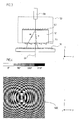
- FIGS. 1 . 2a and 2b Let a first embodiment of the position-measuring device according to the invention be explained below.
- the optical position measuring device of the illustrated embodiment comprises a linear reflection measuring graduation 10, which is arranged at least in the indicated measuring direction x relatively movable relative to a fiber optic scanning head 20.
- the reflection measuring graduation 10 may be stationary and the fiber optic scanning head 20 may be movable or the reflection measuring graduation 10 may be movable and the fiber optic scanning head 20 may be arranged stationary.
- the reflection measuring graduation 10 and the fiber optic scanning head 20 are connected to two objects (not shown) which are movable relative to one another in the measuring direction x and whose relative position is to be determined relative to one another. This may be about two mutually movable components of a machine whose relative position must be detected.
- subsequent electronics to which the position-dependent scanning signals generated by the position-measuring device are fed, a corresponding position or position control with respect to these components can then take place.
- the reflection measuring graduation 10 of the illustrated embodiment is designed as a linear reflection phase grating, which is scanned in the reflected light from the fiber optic scanning head 20.
- the reflection measuring graduation 10 consists of periodically arranged in the measuring direction x division regions with different phase-shifting effects.
- the division areas have a rectangular shape, with the Rectangle longitudinal axis along the specified y-direction extends, which is oriented in the mecanicver stressesungsebene perpendicular to the measuring direction x.
- a rotational reflection measuring graduation in the form of a radial or drum graduation can also be used in the position-measuring device according to the invention.
- the illumination of the reflection measuring graduation 10 takes place by supplying a light beam over an optical fiber 30.
- a spectrally broadband light source 40 is arranged at the end face of the optical fiber remote end 30 whose radiation via coupling means in the form of a collimator lens 41, a beam splitter 42 and a Einkoppellinse 43 is coupled into the optical fiber 30.
- a suitable light source 40 having a sufficiently broad-band emission spectrum e.g. an infrared LED emitting at a central wavelength of 850nm and having a spectral width of 60nm.
- the active area of the light source 40 is imaged via the arrangement shown in the ratio of the focal lengths of the coupling lens 43 and the collimator lens 41 in the coupling surface of the optical fiber 30.
- the imaging ratio here is to optimize the coupling of the maximum possible light output in the optical fiber 30.
- a detector device 50 is furthermore provided in addition to the light source 40, via which the generation of a plurality of phase-shifted scanning signals from the supplied, superimposed partial beams takes place.
- the detector device 50 are supplied by the reflection measuring graduation 10 back-reflected and superimposed partial beams over the optical fiber 30.
- the displacement-dependent scanning signals of a - not shown - subsequent electronics are supplied to them for the purpose of Position control or position control of mutually movable objects uses.
- the various active components of the position-measuring device according to the invention are therefore arranged spatially remote from the actual measuring location and optically coupled thereto only via the optical fiber 30. On the one hand, this minimizes the effects of interference on these components; on the other hand, the passive fiber optic scanning head 20 can be made very compact at the measurement site.
- the optical fiber 30 is preferably designed as a multi-mode fiber, via which both the illuminating beams used for illumination for reflection measuring graduation 10 and the superimposed partial beams used for detection away from the reflection measuring graduation 10 can be transmitted in the direction of the detector unit 50.
- the fiber optic scanning head 20 in the present embodiment comprises a scanning 21, which is located in front of the graduated side end of the optical fiber 30, and a refractive optical element in the form of a lens 22.
- the lens 22 is in this case between the optical fiber 40 and the scanning 21st arranged in the fiber optic scanning head 20.
- About the lens 22 incident from the optical fiber exit surface forth beam is collimated on the way towards reflection measuring standard 10 along the optical axis OA or the direction of the reflection measuring graduation 10 incident thereon partial beam bundled again into the optical fiber 30 or focused on the optical fiber entrance surface.
- a scanning plate 21 is a transparent carrier substrate made of glass, on whose the optical fiber 30 facing side (top) a first Transmission grating 23 and on the reflection of the measuring scale 10 side facing (bottom), a second transmission grating 24 is arranged.
- the beam bundle incident thereon, collimated via the lens 22, is split into at least two diffracted partial beams, which propagate further asymmetrically with respect to a scanning plate normal after the splitting in the scanning plate 21; in the FIG. 1 drawn optical axis OA represents in the present embodiment about such a scanning normal.
- the first transmission grating 23 is formed as a blazed phase grating, the maximum diffraction efficiency in the +1. and -2. Has diffraction order. These two diffraction orders thus represent the asymmetrically propagating partial beams in the scanning beam, which are used to generate the shift-dependent scanning and cover different optical path lengths between splitting and reunification.
- the split partial beams After passing through the scanning 21, the split partial beams reach the second transmission grating 24, which is arranged on the side of the scanning plate 21, which faces the reflection measuring graduation 10.
- the second transmission grating 24 effects a deflection of the partial beams incident from the first transmission grating 23 in such a way that, after passing through the second transmission grating 24, the partial beams propagate symmetrically with respect to a scanning plate normal between the scanning plate 21 and the reflection measuring graduation 10.
- the deflection of the partial beams on the second transmission grating 24 takes place in such a way that they are incident on the reflection measuring graduation 10 at the so-called Littrow angle.
- the second transmission grating 24 is likewise designed as a blazed phase grating; This phase grating is optimized in Terms of maximum diffraction efficiency in the +1. and -1. Diffraction order.
- the partial beams again pass through the second transmission grating 24 on the underside of the scanning plate 21 and again propagate asymmetrically in the scanning plate 21 with respect to a scanning plate normal until reunification at the first transmission grating 23.
- the first transmission grating 23rd at the top of the scanning 21 enter the at this transmission grating in +1. and -2.
- Diffraction order split partial beams for interfering superposition.
- the superimposed pair of partial beams then propagates finally along the optical axis OA in the direction of the lens 22 and is coupled via this into the optical fiber 30.
- a wavelength-dependent coding of the phase-shifted scanning signals is provided.
- the phase-shifted scanning signals are generated from components of the illumination spectrum with different wavelengths.
- Decisive for this is the asymmetrical beam path of the signal-generating partial beams between the splitting and reunification at the first transmission grating and the resulting different optical path lengths that cover the partial beams between splitting and reunification.
- the asymmetrical beam path in this region of the beam path thus causes a wavelength-dependent phase shift between the split partial beams.
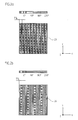
- the first transmission grating 23 has a periodic phase curve ⁇ p (x) along the measuring direction x. This periodicity of the first transmission grating 23 is evident both from the cross-sectional view of the first transmission grating 23 and from FIG schematic top view in FIG. 2a seen.
- TP G1 of the first transmission grating 23 which is designed to be quantized in four stages as shown, four different phase-shifting division areas are provided in the illustrated embodiment, the four phase-shifted scanning signals associated with the phase positions 0 °, 90 °, 180 °, 270 ° ; in the presentation of the FIG. 2a the different phase-shifting division areas are provided with different hatchings.
- the first transmission grating could also be quantized in more than four stages, for example in eight stages.
- the second transmission grating 24 on the scanning plate underside is also formed quantized in four stages, as shown in the cross-sectional view in FIG FIG. 1 and the top view in FIG. 2b can be seen.
- TP G2 of the second transmission grating 24 four different phase-shifting division regions are likewise provided, which are assigned to the four phase-shifted scanning signals with the phase positions 0 °, 90 °, 180 °, 270 °.
- the first transmission grating 23 it may be provided to optimize this for other asymmetrically propagating diffraction orders in the scanning plate 21, ie not for the -2. and + 1. diffraction order, but for other asymmetric diffraction order combinations, eg 0. and 1. diffraction order or +.1 and -3. Diffraction order etc .. Will be next to the +1. Diffraction order instead of -2. Diffraction order another, hereinafter m.
- k 2 - m ⁇ k 1 - k 1 / 2
- k 2 : k vector of the second transmission grating
- k 1 : k vector of the first transmission grating
- k 2 : k vector of the second transmission grating
- k 1 : k vector of the first transmission grating
- the generation of the scanning signals largely independent of variations in the scanning distance between the reflection measuring graduation 10 and the fiber optic scanning head 20 is. This is due to the fact that between the second transmission grating 24 and the reflection measuring graduation 10, the partial beams propagate symmetrically with respect to a scanning plate normal. Due to the illumination of the reflection measuring graduation 10 by two partial beams with symmetrical effective diffraction orders, the path difference between the interfering partial beams is independent of the scanning distance.
- the phase-shifted scanning signals are generated from different spectral components of the illumination spectrum.
- certain sizing considerations are required. For this purpose, one first requires the phase difference ⁇ p ( ⁇ 1 , ⁇ 2 ) of two signals from different wavelengths ⁇ 1 , ⁇ 2 of the illumination spectrum, expressed in signal periods.
- the light source used here is an infrared LED with a central wavelength of 850 nm and a spectral width of 60 nm. Should four phase-shifted scanning signals be obtained on the output side, Thus, the double sampling of each of the four signal components from the entire wavelength range of the light source lends itself. Thus, eight signal components with a phase shift of 90 ° each must be obtained from the available light source spectral range of 60 nm. With a correspondingly high receiver-side spectral resolution, an even higher-numbered sampling of the signal components is also conceivable. This leads to a better stability with a change of the light source spectrum, for example due to temperature influences.
- the thickness d Ap of the scanning 21 and / or the lattice parameters of the arranged thereon transmission grating must be dimensioned so that it is clear at a wavelength shift of 30 nm, a phase shift of 1 (360 °).
- quartz is used as the material for the scanning plate 21 (n ref ⁇ 1.452).
- the thickness d Ap of the scanning plate 21 and / or the lattice parameters of the transmission gratings arranged thereon are accordingly dimensioned in the position measuring device according to the invention such that according to equation (5) the corresponding phase shift results per wavelength change.
- the detector device 50 which serves to detect the wavelength-coded, phase-shifted scanning signals.
- the detector device 50 which is arranged at the end of the optical fiber 30 facing away from the measuring element, comprises a schematically indicated splitting means 51 for the wavelength-dependent separation of the superimposed partial beams, which transmit via the optical fiber 30 in the direction of the detector device 50 become.
- the splitting means 51 is formed in the present example as a dispersive element in the form of a diffraction grating.
- the light is focused onto a structured photodetector 53, which here consists of eight individual detector elements, via a lens 52 arranged downstream of the splitting means 51.
- the imaged light of a certain wavelength forms a circle in the focal plane, the diameter of which is given by the product of the fiber core diameter of the optical fiber 30 and the focal length ratio of the lens 52 and the coupling lens 43.
- the dispersion of the splitting means 51 must therefore be sufficiently large so that the circular images of the fiber end are spatially separated and thus resolved detectable. In the present embodiment, a phase shift of 30 nm / 360 ° was assumed.
- each scanning signal can in this case be scanned several times with a phase shift of 360 ° each. In this way, the complete light source spectrum can be used, while, for example, a temperature-induced wavelength shift has little effect on the amplitudes of the generated scanning signals.
- FIG. 1 Not in FIG. 1 are shown further components for signal processing, which may optionally be additionally arranged in the detector device 50. These include, for example, amplifier modules, A / D converters, etc., via which further electronic processing and processing of the scanning signals takes place before they are transmitted to a subsequent electronic unit (not shown) for further processing.
- a further advantage is a reduction of the direct light component, which passes into the detection channel by reflection of the coupled-in light at the fiber end. This can be achieved by applying an antireflection coating to the fiber end. Alternatively or additionally, it can be prevented by oblique grinding of the fiber end that the light reflected during coupling reaches the detection channel.
- the unmodulated spectrum can also be measured in the device according to the invention.
- the light reflected at the oblique fiber end can be deflected, for example, by a prism or a diffractive element between the outcoupling fiber end and the coupling lens, so that the reflected light is emitted virtually from a point offset from the fiber end.
- the information thus obtained can be used to correct for signal errors resulting from a change in the illumination spectrum.
- FIG. 3 A comparison with the first embodiment, slightly modified second embodiment of the optical position measuring device according to the invention is shown in FIG. 3 partially shown; only the components at the measurement location are shown here, ie the fiber-optics scanning head 120 and the reflection measuring graduation 110.
- the illustration of the various components at the end of the optical fiber 130 facing away from the measuring element was omitted; these are identical to the first embodiment. In the following, only the relevant differences from the first exemplary embodiment will be explained.
- the fiber optic scanning head 120 no longer contains a separate lens between the optical fiber 130 and the first transmission grating 123 on top of the scanning plate 121.
- the corresponding optical functionality of this lens is additionally integrated into the first transmission grating 123.
- the first transmission grating 123 also exerts a collimating effect on the radiation beam incident from the optical fiber 120.
- the superimposed partial beam bundles propagating in the reverse direction are coupled into the optical fiber 130 and focused for this purpose in the corresponding optical fiber entrance surface. This results in a comparison with the first embodiment even more compact fiber optic scanning head 120; Moreover, the adjustment effort with respect to a separate lens in the production of the device according to the invention is eliminated.
- FIG. 4 A plan view of the resulting phase curve of the first transmission grating 123 with the additional optical functionality is shown FIG. 4 .
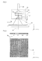
- FIGS. 5 and 6 A third embodiment of the optical position-measuring device according to the invention is in the FIGS. 5 and 6 shown. In the following, the description of the same will primarily deal with the relevant differences from the first exemplary embodiments.
- FIG. 6 schematically illustrates the phase profile of the first transmission grating.
- the coupling of light into the optical fiber 230 and the detection of the superimposed partial beams is analogous to the previously described embodiments.
- the beam emanating from the optical fiber 230 in the fiber optic scanning head 220 is collimated via a lens 222 on the way towards the reflection measuring standard 210 along the optical axis OA, as in the first exemplary embodiment.
- the collimated beam then passes through a polarizer 225, through which the beam receives a linear polarization, the polarization direction is oriented in the measuring direction x.
- the linearly polarized radiation beam impinges on the scanning plate 221, specifically on a first transmission grating 223, which is arranged on the side of the scanning plate 221 facing the optical fiber 230.
- the first transmission grating 2223 in this exemplary embodiment, in contrast to the two preceding variants, a splitting of the incident beam into sub-beam beams +1. and -1. Diffraction order causes.
- the first transmission grating 223 is designed as a phase grating and has a pitch period TP G1 which corresponds to half the pitch period TP M of the reflection measuring standard 210.
- the split partial beams then propagate through the scanning plate 221 and enter a birefringent element 226, which is arranged on the side of the scanning plate 221 facing the reflection measuring graduation 210.
- the birefringent element 226 of the scanning plate 221 the split partial beams propagate further asymmetrically. This is caused by the orientation chosen of the birefringent element 226 such that due to the linear polarization of the partial beams in the measuring direction x, the propagation of the ordinary beams in the birefringent element 226 is suppressed.
- the polarization ellipsoids of the birefringent element 226 are oriented at an angle not equal to 0 ° and not equal to 90 ° to the scanning plate normal.
- the refractive indices of the two extraordinary beams which originate in the two 1st diffraction orders of the first transmission grating 223, are different. This is due to the different relative angles of the major axes of the birefringent element 225 to the propagation directions of the two partial beams
- phase difference ⁇ p ( ⁇ 1 , ⁇ 2 ) of two signals based on different wavelengths ⁇ 1 , ⁇ 2 , expressed in signal periods is required.
- the refractive index n r depends both on the respective wavelength ⁇ 1 , ⁇ 2 and on the illumination direction ⁇ 1 or ⁇ 2 .
- n o : refractive index of the ordinary ray
- n e : refractive index of the extraordinary ray.
- ⁇ : angle between beam direction ⁇ 1 , ⁇ 2 and orientation angle ⁇ of the birefringent element
- the refractive indices n 0 , n e are to be determined from the dispersion formula of the corresponding birefringent material at the respective wavelength.
- a light source which has a center wavelength of 850nm and a spectral width of 60nm.
- a material for the birefringent element 226 calcite is provided.
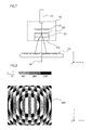
- FIGS. 7 and 8 A fourth embodiment of the optical position measuring device according to the invention described.
- the fourth embodiment is based on the above-explained third embodiment and differs from this i.w. only in that, as already provided in the second embodiment, the optical functionality of the lens 222 is now integrated into the first transmission grating 323 on the upper side of the scanning plate 321.
- the first transmission grating 323 exerts, in addition to the beam-splitting optical functions, also a collimating effect on the beam of rays incident on the optical fiber 320.
- the superimposed partial beams propagating in the reverse direction are coupled into the optical fiber 330 via this and focused for this purpose into the corresponding optical fiber entry surface.
- FIG. 8 A plan view of the then resulting phase curve of the first transmission grating 323 with the additional optical functionality shows FIG. 8 .
- a composite light source or light source unit instead of a single broadband light source, which consists of a plurality of individual light sources with different individual wavelengths.
- laser diodes, VCSELs, LEDS, OLEDs, etc. may be used here as the light source.
- dichroic mirrors or a suitable dispersive element the light from these different light sources can be combined and coupled together into the optical fiber.
Landscapes
- Physics & Mathematics (AREA)
- General Physics & Mathematics (AREA)
- Optical Transform (AREA)
- Length Measuring Devices By Optical Means (AREA)
Applications Claiming Priority (2)
| Application Number | Priority Date | Filing Date | Title |
|---|---|---|---|
| DE102013201904 | 2013-02-06 | ||
| DE102013222383.8A DE102013222383A1 (de) | 2013-02-06 | 2013-11-05 | Optische Positionsmesseinrichtung |
Publications (3)
| Publication Number | Publication Date |
|---|---|
| EP2765394A2 true EP2765394A2 (fr) | 2014-08-13 |
| EP2765394A3 EP2765394A3 (fr) | 2017-04-19 |
| EP2765394B1 EP2765394B1 (fr) | 2018-05-23 |
Family
ID=49998175
Family Applications (1)
| Application Number | Title | Priority Date | Filing Date |
|---|---|---|---|
| EP14152674.9A Active EP2765394B1 (fr) | 2013-02-06 | 2014-01-27 | Dispositif optique de mesure de la position |
Country Status (6)
| Country | Link |
|---|---|
| US (1) | US9395176B2 (fr) |
| EP (1) | EP2765394B1 (fr) |
| JP (1) | JP6332987B2 (fr) |
| CN (1) | CN103968862B (fr) |
| DE (1) | DE102013222383A1 (fr) |
| ES (1) | ES2672977T3 (fr) |
Cited By (2)
| Publication number | Priority date | Publication date | Assignee | Title |
|---|---|---|---|---|
| DE102015218539A1 (de) | 2014-10-21 | 2016-04-21 | Dr. Johannes Heidenhain Gmbh | Optische Positionsmesseinrichtung |
| EP3605026A1 (fr) * | 2018-07-31 | 2020-02-05 | Dr. Johannes Heidenhain GmbH | Dispositif optique de mesure de position |
Families Citing this family (11)
| Publication number | Priority date | Publication date | Assignee | Title |
|---|---|---|---|---|
| DE102016013880A1 (de) | 2016-01-14 | 2017-07-20 | Sew-Eurodrive Gmbh & Co Kg | System, umfassend ein erstes Teil und ein zweites Teil |
| US9970845B2 (en) * | 2016-02-10 | 2018-05-15 | Apple Inc. | Interrogating DOE integrity by reverse illumination |
| JP6400035B2 (ja) | 2016-03-14 | 2018-10-03 | キヤノン株式会社 | 位置検出装置、力覚センサ、および、装置 |
| DE102016211150A1 (de) * | 2016-06-22 | 2017-12-28 | Dr. Johannes Heidenhain Gmbh | Optische Positionsmesseinrichtung |
| CN106037657B (zh) * | 2016-06-28 | 2017-11-21 | 丹阳慧创医疗设备有限公司 | 一种时空频多重耦合的高密度近红外光谱脑功能成像方法 |
| CN106405901B (zh) * | 2016-12-16 | 2019-05-24 | 武汉邮电科学研究院 | 一种测量硅基液晶相位分辨率的装置及方法 |
| DE102017201257A1 (de) * | 2017-01-26 | 2018-07-26 | Dr. Johannes Heidenhain Gmbh | Positionsmesseinrichtung |
| US11422292B1 (en) * | 2018-06-10 | 2022-08-23 | Apple Inc. | Super-blazed diffractive optical elements with sub-wavelength structures |
| US11754767B1 (en) | 2020-03-05 | 2023-09-12 | Apple Inc. | Display with overlaid waveguide |
| WO2022197339A1 (fr) | 2021-03-17 | 2022-09-22 | Apple Inc. | Émetteurs à base de guide d'ondes à éclairage réglable |
| DE112022007293T5 (de) * | 2022-05-27 | 2025-03-20 | Hamamatsu Photonics K.K. | Optischer Detektor und spektroskopische Messvorrichtung |
Citations (1)
| Publication number | Priority date | Publication date | Assignee | Title |
|---|---|---|---|---|
| DE102007024349A1 (de) | 2007-05-24 | 2008-11-27 | Dr. Johannes Heidenhain Gmbh | Optische Positionsmesseinrichtung |
Family Cites Families (14)
| Publication number | Priority date | Publication date | Assignee | Title |
|---|---|---|---|---|
| DE69223916T2 (de) * | 1991-10-03 | 1998-05-28 | Canon K.K., Tokio/Tokyo | Optische Kodiereinrichtung |
| US5424833A (en) | 1992-09-21 | 1995-06-13 | Dr. Johannes Heidenhain Gmbh | Interferential linear and angular displacement apparatus having scanning and scale grating respectively greater than and less than the source wavelength |
| JPH06194123A (ja) * | 1992-12-24 | 1994-07-15 | Canon Inc | 変位検出装置 |
| DE29805392U1 (de) | 1998-03-25 | 1999-08-05 | Dr. Johannes Heidenhain Gmbh, 83301 Traunreut | Optoelektronische Baugruppe |
| DE10339366A1 (de) | 2003-08-27 | 2005-03-24 | Dr. Johannes Heidenhain Gmbh | Verfahren und Vorrichtung zur Regelung einer Lichtquelle eines Positionsmessgerätes |
| US20050083534A1 (en) * | 2003-08-28 | 2005-04-21 | Riza Nabeel A. | Agile high sensitivity optical sensor |
| JP4969057B2 (ja) * | 2004-12-13 | 2012-07-04 | 株式会社森精機製作所 | 変位検出装置及び変位計測装置並びに定点検出装置 |
| DE102005029917A1 (de) * | 2005-06-28 | 2007-01-04 | Dr. Johannes Heidenhain Gmbh | Positionsmesseinrichtung |
| CN101305265B (zh) * | 2005-11-09 | 2010-10-27 | 约翰尼斯海登海恩博士股份有限公司 | 位置测量系统 |
| US7502122B2 (en) * | 2006-07-31 | 2009-03-10 | Mitutoyo Corporation | Fiber-optic miniature encoder for fine pitch scales |
| DE102008020902B4 (de) * | 2008-04-18 | 2010-07-29 | Universität Stuttgart | Anordnung und Verfahren zur konfokalen, spektralen Zweistrahl-Interferometrie |
| DE102010003157B4 (de) * | 2010-03-23 | 2019-10-24 | Dr. Johannes Heidenhain Gmbh | Vorrichtung zur interferentiellen Abstandsmessung |
| JP5517753B2 (ja) * | 2010-06-03 | 2014-06-11 | キヤノン株式会社 | 干渉計測装置 |
| DE102011082156A1 (de) * | 2010-12-16 | 2012-06-21 | Dr. Johannes Heidenhain Gmbh | Optische Positionsmesseinrichtung |
-
2013
- 2013-11-05 DE DE102013222383.8A patent/DE102013222383A1/de not_active Withdrawn
-
2014
- 2014-01-15 US US14/155,447 patent/US9395176B2/en active Active
- 2014-01-27 ES ES14152674.9T patent/ES2672977T3/es active Active
- 2014-01-27 EP EP14152674.9A patent/EP2765394B1/fr active Active
- 2014-01-27 CN CN201410041202.0A patent/CN103968862B/zh not_active Expired - Fee Related
- 2014-02-04 JP JP2014019238A patent/JP6332987B2/ja not_active Expired - Fee Related
Patent Citations (1)
| Publication number | Priority date | Publication date | Assignee | Title |
|---|---|---|---|---|
| DE102007024349A1 (de) | 2007-05-24 | 2008-11-27 | Dr. Johannes Heidenhain Gmbh | Optische Positionsmesseinrichtung |
Cited By (5)
| Publication number | Priority date | Publication date | Assignee | Title |
|---|---|---|---|---|
| DE102015218539A1 (de) | 2014-10-21 | 2016-04-21 | Dr. Johannes Heidenhain Gmbh | Optische Positionsmesseinrichtung |
| US10082410B2 (en) | 2014-10-21 | 2018-09-25 | Dr. Johannes Heidenhain Gmbh | Optical position measuring device for generating wavelength-dependent scanning signals |
| DE102015218539B4 (de) | 2014-10-21 | 2022-07-14 | Dr. Johannes Heidenhain Gmbh | Optische Positionsmesseinrichtung |
| EP3605026A1 (fr) * | 2018-07-31 | 2020-02-05 | Dr. Johannes Heidenhain GmbH | Dispositif optique de mesure de position |
| US10823550B2 (en) | 2018-07-31 | 2020-11-03 | Dr. Johannes Heidenhain Gmbh | Optical position measuring device |
Also Published As
| Publication number | Publication date |
|---|---|
| DE102013222383A1 (de) | 2014-08-07 |
| CN103968862A (zh) | 2014-08-06 |
| US20140218746A1 (en) | 2014-08-07 |
| CN103968862B (zh) | 2018-03-06 |
| JP2014153360A (ja) | 2014-08-25 |
| ES2672977T3 (es) | 2018-06-19 |
| EP2765394B1 (fr) | 2018-05-23 |
| US9395176B2 (en) | 2016-07-19 |
| EP2765394A3 (fr) | 2017-04-19 |
| JP6332987B2 (ja) | 2018-05-30 |
Similar Documents
| Publication | Publication Date | Title |
|---|---|---|
| EP2765394B1 (fr) | Dispositif optique de mesure de la position | |
| DE19821616B4 (de) | Anordnung zur Bestimmung von absoluten physikalischen Zustandsgrößen, insbesondere Temperatur und Dehnung, einer optischen Faser | |
| EP1901041B1 (fr) | Dispositif de mesure de position | |
| EP2474815B1 (fr) | Dispositif optique de mesure de la position | |
| DE102007024349A1 (de) | Optische Positionsmesseinrichtung | |
| DE102015218539B4 (de) | Optische Positionsmesseinrichtung | |
| DE68909320T2 (de) | Interferometrischer Sensor und seine Anwendung in einer interferometrischen Vorrichtung. | |
| DE102010003157B4 (de) | Vorrichtung zur interferentiellen Abstandsmessung | |
| EP3447441B1 (fr) | Dispositif de mesure de distance interférométrique | |
| EP3059554B1 (fr) | Dispositif optique de mesure de position | |
| DE19930687B4 (de) | Optisches Verschiebungsmeßsystem | |
| EP2333493A2 (fr) | Dispositif de mesure de position | |
| DE69223916T2 (de) | Optische Kodiereinrichtung | |
| EP2955489B1 (fr) | Dispositif optique de mesure de position | |
| DE10308016B4 (de) | Verschiebungsmessgerät mit Interferenzgitter | |
| DE19938869B4 (de) | Optisches Verschiebungsmeßsystem | |
| DE3915143A1 (de) | Optischer geber | |
| DE102016200847A1 (de) | Optische Positionsmesseinrichtung | |
| DE3836703C2 (fr) | ||
| EP0625690A1 (fr) | Dispositif de mesure de position optoélectrique | |
| EP3477264B1 (fr) | Dispositif optique de mesure de position | |
| EP1992915B1 (fr) | Dispositif de mesure de position | |
| DE102011005937B4 (de) | Vorrichtung zur interferentiellen Abstandsmessung | |
| EP2813802B1 (fr) | Dispositif de mesure | |
| EP1231454B1 (fr) | Dispositif et méthode pour effectuer des mesures interférométriques |
Legal Events
| Date | Code | Title | Description |
|---|---|---|---|
| PUAI | Public reference made under article 153(3) epc to a published international application that has entered the european phase |
Free format text: ORIGINAL CODE: 0009012 |
|
| 17P | Request for examination filed |
Effective date: 20140127 |
|
| AK | Designated contracting states |
Kind code of ref document: A2 Designated state(s): AL AT BE BG CH CY CZ DE DK EE ES FI FR GB GR HR HU IE IS IT LI LT LU LV MC MK MT NL NO PL PT RO RS SE SI SK SM TR |
|
| AX | Request for extension of the european patent |
Extension state: BA ME |
|
| PUAL | Search report despatched |
Free format text: ORIGINAL CODE: 0009013 |
|
| AK | Designated contracting states |
Kind code of ref document: A3 Designated state(s): AL AT BE BG CH CY CZ DE DK EE ES FI FR GB GR HR HU IE IS IT LI LT LU LV MC MK MT NL NO PL PT RO RS SE SI SK SM TR |
|
| AX | Request for extension of the european patent |
Extension state: BA ME |
|
| RIC1 | Information provided on ipc code assigned before grant |
Ipc: G01D 5/38 20060101ALI20170316BHEP Ipc: G01D 5/26 20060101AFI20170316BHEP |
|
| STAA | Information on the status of an ep patent application or granted ep patent |
Free format text: STATUS: REQUEST FOR EXAMINATION WAS MADE |
|
| R17P | Request for examination filed (corrected) |
Effective date: 20170803 |
|
| RBV | Designated contracting states (corrected) |
Designated state(s): AL AT BE BG CH CY CZ DE DK EE ES FI FR GB GR HR HU IE IS IT LI LT LU LV MC MK MT NL NO PL PT RO RS SE SI SK SM TR |
|
| GRAP | Despatch of communication of intention to grant a patent |
Free format text: ORIGINAL CODE: EPIDOSNIGR1 |
|
| STAA | Information on the status of an ep patent application or granted ep patent |
Free format text: STATUS: GRANT OF PATENT IS INTENDED |
|
| INTG | Intention to grant announced |
Effective date: 20180207 |
|
| GRAS | Grant fee paid |
Free format text: ORIGINAL CODE: EPIDOSNIGR3 |
|
| GRAA | (expected) grant |
Free format text: ORIGINAL CODE: 0009210 |
|
| STAA | Information on the status of an ep patent application or granted ep patent |
Free format text: STATUS: THE PATENT HAS BEEN GRANTED |
|
| AK | Designated contracting states |
Kind code of ref document: B1 Designated state(s): AL AT BE BG CH CY CZ DE DK EE ES FI FR GB GR HR HU IE IS IT LI LT LU LV MC MK MT NL NO PL PT RO RS SE SI SK SM TR |
|
| REG | Reference to a national code |
Ref country code: GB Ref legal event code: FG4D Free format text: NOT ENGLISH |
|
| REG | Reference to a national code |
Ref country code: CH Ref legal event code: EP |
|
| REG | Reference to a national code |
Ref country code: IE Ref legal event code: FG4D Free format text: LANGUAGE OF EP DOCUMENT: GERMAN |
|
| REG | Reference to a national code |
Ref country code: AT Ref legal event code: REF Ref document number: 1001882 Country of ref document: AT Kind code of ref document: T Effective date: 20180615 |
|
| REG | Reference to a national code |
Ref country code: ES Ref legal event code: FG2A Ref document number: 2672977 Country of ref document: ES Kind code of ref document: T3 Effective date: 20180619 |
|
| REG | Reference to a national code |
Ref country code: DE Ref legal event code: R096 Ref document number: 502014008317 Country of ref document: DE |
|
| REG | Reference to a national code |
Ref country code: NL Ref legal event code: MP Effective date: 20180523 |
|
| REG | Reference to a national code |
Ref country code: LT Ref legal event code: MG4D |
|
| PG25 | Lapsed in a contracting state [announced via postgrant information from national office to epo] |
Ref country code: FI Free format text: LAPSE BECAUSE OF FAILURE TO SUBMIT A TRANSLATION OF THE DESCRIPTION OR TO PAY THE FEE WITHIN THE PRESCRIBED TIME-LIMIT Effective date: 20180523 Ref country code: BG Free format text: LAPSE BECAUSE OF FAILURE TO SUBMIT A TRANSLATION OF THE DESCRIPTION OR TO PAY THE FEE WITHIN THE PRESCRIBED TIME-LIMIT Effective date: 20180823 Ref country code: SE Free format text: LAPSE BECAUSE OF FAILURE TO SUBMIT A TRANSLATION OF THE DESCRIPTION OR TO PAY THE FEE WITHIN THE PRESCRIBED TIME-LIMIT Effective date: 20180523 Ref country code: NO Free format text: LAPSE BECAUSE OF FAILURE TO SUBMIT A TRANSLATION OF THE DESCRIPTION OR TO PAY THE FEE WITHIN THE PRESCRIBED TIME-LIMIT Effective date: 20180823 Ref country code: LT Free format text: LAPSE BECAUSE OF FAILURE TO SUBMIT A TRANSLATION OF THE DESCRIPTION OR TO PAY THE FEE WITHIN THE PRESCRIBED TIME-LIMIT Effective date: 20180523 |
|
| PG25 | Lapsed in a contracting state [announced via postgrant information from national office to epo] |
Ref country code: LV Free format text: LAPSE BECAUSE OF FAILURE TO SUBMIT A TRANSLATION OF THE DESCRIPTION OR TO PAY THE FEE WITHIN THE PRESCRIBED TIME-LIMIT Effective date: 20180523 Ref country code: NL Free format text: LAPSE BECAUSE OF FAILURE TO SUBMIT A TRANSLATION OF THE DESCRIPTION OR TO PAY THE FEE WITHIN THE PRESCRIBED TIME-LIMIT Effective date: 20180523 Ref country code: HR Free format text: LAPSE BECAUSE OF FAILURE TO SUBMIT A TRANSLATION OF THE DESCRIPTION OR TO PAY THE FEE WITHIN THE PRESCRIBED TIME-LIMIT Effective date: 20180523 Ref country code: RS Free format text: LAPSE BECAUSE OF FAILURE TO SUBMIT A TRANSLATION OF THE DESCRIPTION OR TO PAY THE FEE WITHIN THE PRESCRIBED TIME-LIMIT Effective date: 20180523 Ref country code: GR Free format text: LAPSE BECAUSE OF FAILURE TO SUBMIT A TRANSLATION OF THE DESCRIPTION OR TO PAY THE FEE WITHIN THE PRESCRIBED TIME-LIMIT Effective date: 20180824 |
|
| PG25 | Lapsed in a contracting state [announced via postgrant information from national office to epo] |
Ref country code: EE Free format text: LAPSE BECAUSE OF FAILURE TO SUBMIT A TRANSLATION OF THE DESCRIPTION OR TO PAY THE FEE WITHIN THE PRESCRIBED TIME-LIMIT Effective date: 20180523 Ref country code: DK Free format text: LAPSE BECAUSE OF FAILURE TO SUBMIT A TRANSLATION OF THE DESCRIPTION OR TO PAY THE FEE WITHIN THE PRESCRIBED TIME-LIMIT Effective date: 20180523 Ref country code: CZ Free format text: LAPSE BECAUSE OF FAILURE TO SUBMIT A TRANSLATION OF THE DESCRIPTION OR TO PAY THE FEE WITHIN THE PRESCRIBED TIME-LIMIT Effective date: 20180523 Ref country code: RO Free format text: LAPSE BECAUSE OF FAILURE TO SUBMIT A TRANSLATION OF THE DESCRIPTION OR TO PAY THE FEE WITHIN THE PRESCRIBED TIME-LIMIT Effective date: 20180523 Ref country code: SK Free format text: LAPSE BECAUSE OF FAILURE TO SUBMIT A TRANSLATION OF THE DESCRIPTION OR TO PAY THE FEE WITHIN THE PRESCRIBED TIME-LIMIT Effective date: 20180523 Ref country code: PL Free format text: LAPSE BECAUSE OF FAILURE TO SUBMIT A TRANSLATION OF THE DESCRIPTION OR TO PAY THE FEE WITHIN THE PRESCRIBED TIME-LIMIT Effective date: 20180523 |
|
| REG | Reference to a national code |
Ref country code: DE Ref legal event code: R097 Ref document number: 502014008317 Country of ref document: DE |
|
| PG25 | Lapsed in a contracting state [announced via postgrant information from national office to epo] |
Ref country code: SM Free format text: LAPSE BECAUSE OF FAILURE TO SUBMIT A TRANSLATION OF THE DESCRIPTION OR TO PAY THE FEE WITHIN THE PRESCRIBED TIME-LIMIT Effective date: 20180523 Ref country code: IT Free format text: LAPSE BECAUSE OF FAILURE TO SUBMIT A TRANSLATION OF THE DESCRIPTION OR TO PAY THE FEE WITHIN THE PRESCRIBED TIME-LIMIT Effective date: 20180523 |
|
| PLBE | No opposition filed within time limit |
Free format text: ORIGINAL CODE: 0009261 |
|
| STAA | Information on the status of an ep patent application or granted ep patent |
Free format text: STATUS: NO OPPOSITION FILED WITHIN TIME LIMIT |
|
| 26N | No opposition filed |
Effective date: 20190226 |
|
| PG25 | Lapsed in a contracting state [announced via postgrant information from national office to epo] |
Ref country code: SI Free format text: LAPSE BECAUSE OF FAILURE TO SUBMIT A TRANSLATION OF THE DESCRIPTION OR TO PAY THE FEE WITHIN THE PRESCRIBED TIME-LIMIT Effective date: 20180523 |
|
| PG25 | Lapsed in a contracting state [announced via postgrant information from national office to epo] |
Ref country code: MC Free format text: LAPSE BECAUSE OF FAILURE TO SUBMIT A TRANSLATION OF THE DESCRIPTION OR TO PAY THE FEE WITHIN THE PRESCRIBED TIME-LIMIT Effective date: 20180523 |
|
| REG | Reference to a national code |
Ref country code: CH Ref legal event code: PL |
|
| PG25 | Lapsed in a contracting state [announced via postgrant information from national office to epo] |
Ref country code: LU Free format text: LAPSE BECAUSE OF NON-PAYMENT OF DUE FEES Effective date: 20190127 |
|
| REG | Reference to a national code |
Ref country code: BE Ref legal event code: MM Effective date: 20190131 |
|
| REG | Reference to a national code |
Ref country code: IE Ref legal event code: MM4A |
|
| PG25 | Lapsed in a contracting state [announced via postgrant information from national office to epo] |
Ref country code: FR Free format text: LAPSE BECAUSE OF NON-PAYMENT OF DUE FEES Effective date: 20190131 |
|
| PG25 | Lapsed in a contracting state [announced via postgrant information from national office to epo] |
Ref country code: AL Free format text: LAPSE BECAUSE OF FAILURE TO SUBMIT A TRANSLATION OF THE DESCRIPTION OR TO PAY THE FEE WITHIN THE PRESCRIBED TIME-LIMIT Effective date: 20180523 Ref country code: BE Free format text: LAPSE BECAUSE OF NON-PAYMENT OF DUE FEES Effective date: 20190131 |
|
| PG25 | Lapsed in a contracting state [announced via postgrant information from national office to epo] |
Ref country code: LI Free format text: LAPSE BECAUSE OF NON-PAYMENT OF DUE FEES Effective date: 20190131 Ref country code: CH Free format text: LAPSE BECAUSE OF NON-PAYMENT OF DUE FEES Effective date: 20190131 |
|
| PG25 | Lapsed in a contracting state [announced via postgrant information from national office to epo] |
Ref country code: IE Free format text: LAPSE BECAUSE OF NON-PAYMENT OF DUE FEES Effective date: 20190127 |
|
| REG | Reference to a national code |
Ref country code: AT Ref legal event code: MM01 Ref document number: 1001882 Country of ref document: AT Kind code of ref document: T Effective date: 20190127 |
|
| PG25 | Lapsed in a contracting state [announced via postgrant information from national office to epo] |
Ref country code: TR Free format text: LAPSE BECAUSE OF FAILURE TO SUBMIT A TRANSLATION OF THE DESCRIPTION OR TO PAY THE FEE WITHIN THE PRESCRIBED TIME-LIMIT Effective date: 20180523 |
|
| PG25 | Lapsed in a contracting state [announced via postgrant information from national office to epo] |
Ref country code: AT Free format text: LAPSE BECAUSE OF NON-PAYMENT OF DUE FEES Effective date: 20190127 |
|
| PG25 | Lapsed in a contracting state [announced via postgrant information from national office to epo] |
Ref country code: PT Free format text: LAPSE BECAUSE OF FAILURE TO SUBMIT A TRANSLATION OF THE DESCRIPTION OR TO PAY THE FEE WITHIN THE PRESCRIBED TIME-LIMIT Effective date: 20180924 Ref country code: MT Free format text: LAPSE BECAUSE OF FAILURE TO SUBMIT A TRANSLATION OF THE DESCRIPTION OR TO PAY THE FEE WITHIN THE PRESCRIBED TIME-LIMIT Effective date: 20180523 |
|
| PG25 | Lapsed in a contracting state [announced via postgrant information from national office to epo] |
Ref country code: CY Free format text: LAPSE BECAUSE OF FAILURE TO SUBMIT A TRANSLATION OF THE DESCRIPTION OR TO PAY THE FEE WITHIN THE PRESCRIBED TIME-LIMIT Effective date: 20180523 |
|
| PG25 | Lapsed in a contracting state [announced via postgrant information from national office to epo] |
Ref country code: IS Free format text: LAPSE BECAUSE OF FAILURE TO SUBMIT A TRANSLATION OF THE DESCRIPTION OR TO PAY THE FEE WITHIN THE PRESCRIBED TIME-LIMIT Effective date: 20180923 |
|
| PG25 | Lapsed in a contracting state [announced via postgrant information from national office to epo] |
Ref country code: HU Free format text: LAPSE BECAUSE OF FAILURE TO SUBMIT A TRANSLATION OF THE DESCRIPTION OR TO PAY THE FEE WITHIN THE PRESCRIBED TIME-LIMIT; INVALID AB INITIO Effective date: 20140127 |
|
| PG25 | Lapsed in a contracting state [announced via postgrant information from national office to epo] |
Ref country code: MK Free format text: LAPSE BECAUSE OF FAILURE TO SUBMIT A TRANSLATION OF THE DESCRIPTION OR TO PAY THE FEE WITHIN THE PRESCRIBED TIME-LIMIT Effective date: 20180523 |
|
| PGFP | Annual fee paid to national office [announced via postgrant information from national office to epo] |
Ref country code: GB Payment date: 20230119 Year of fee payment: 10 |
|
| PGFP | Annual fee paid to national office [announced via postgrant information from national office to epo] |
Ref country code: ES Payment date: 20230405 Year of fee payment: 10 |
|
| GBPC | Gb: european patent ceased through non-payment of renewal fee |
Effective date: 20240127 |
|
| PG25 | Lapsed in a contracting state [announced via postgrant information from national office to epo] |
Ref country code: GB Free format text: LAPSE BECAUSE OF NON-PAYMENT OF DUE FEES Effective date: 20240127 |
|
| PG25 | Lapsed in a contracting state [announced via postgrant information from national office to epo] |
Ref country code: GB Free format text: LAPSE BECAUSE OF NON-PAYMENT OF DUE FEES Effective date: 20240127 |
|
| PG25 | Lapsed in a contracting state [announced via postgrant information from national office to epo] |
Ref country code: ES Free format text: LAPSE BECAUSE OF NON-PAYMENT OF DUE FEES Effective date: 20240128 |
|
| PGFP | Annual fee paid to national office [announced via postgrant information from national office to epo] |
Ref country code: DE Payment date: 20260121 Year of fee payment: 13 |