EP2765732A2 - Procédé et appareil de transmission de positionnement d'un signal de référence sonore de canal dans un système de communication sans fil - Google Patents
Procédé et appareil de transmission de positionnement d'un signal de référence sonore de canal dans un système de communication sans fil Download PDFInfo
- Publication number
- EP2765732A2 EP2765732A2 EP14154125.0A EP14154125A EP2765732A2 EP 2765732 A2 EP2765732 A2 EP 2765732A2 EP 14154125 A EP14154125 A EP 14154125A EP 2765732 A2 EP2765732 A2 EP 2765732A2
- Authority
- EP
- European Patent Office
- Prior art keywords
- channel
- transmission
- srs
- control channel
- carrier
- Prior art date
- Legal status (The legal status is an assumption and is not a legal conclusion. Google has not performed a legal analysis and makes no representation as to the accuracy of the status listed.)
- Granted
Links
Images






Classifications
-
- H—ELECTRICITY
- H04—ELECTRIC COMMUNICATION TECHNIQUE
- H04L—TRANSMISSION OF DIGITAL INFORMATION, e.g. TELEGRAPHIC COMMUNICATION
- H04L5/00—Arrangements affording multiple use of the transmission path
- H04L5/003—Arrangements for allocating sub-channels of the transmission path
- H04L5/0048—Allocation of pilot signals, i.e. of signals known to the receiver
- H04L5/0051—Allocation of pilot signals, i.e. of signals known to the receiver of dedicated pilots, i.e. pilots destined for a single user or terminal
-
- H—ELECTRICITY
- H04—ELECTRIC COMMUNICATION TECHNIQUE
- H04L—TRANSMISSION OF DIGITAL INFORMATION, e.g. TELEGRAPHIC COMMUNICATION
- H04L5/00—Arrangements affording multiple use of the transmission path
- H04L5/003—Arrangements for allocating sub-channels of the transmission path
- H04L5/0048—Allocation of pilot signals, i.e. of signals known to the receiver
-
- H—ELECTRICITY
- H04—ELECTRIC COMMUNICATION TECHNIQUE
- H04W—WIRELESS COMMUNICATION NETWORKS
- H04W52/00—Power management, e.g. Transmission Power Control [TPC] or power classes
- H04W52/04—Transmission power control [TPC]
- H04W52/30—Transmission power control [TPC] using constraints in the total amount of available transmission power
- H04W52/32—TPC of broadcast or control channels
- H04W52/325—Power control of control or pilot channels
-
- H—ELECTRICITY
- H04—ELECTRIC COMMUNICATION TECHNIQUE
- H04W—WIRELESS COMMUNICATION NETWORKS
- H04W72/00—Local resource management
- H04W72/20—Control channels or signalling for resource management
- H04W72/21—Control channels or signalling for resource management in the uplink direction of a wireless link, i.e. towards the network
-
- H—ELECTRICITY
- H04—ELECTRIC COMMUNICATION TECHNIQUE
- H04W—WIRELESS COMMUNICATION NETWORKS
- H04W88/00—Devices specially adapted for wireless communication networks, e.g. terminals, base stations or access point devices
- H04W88/08—Access point devices
-
- H—ELECTRICITY
- H04—ELECTRIC COMMUNICATION TECHNIQUE
- H04L—TRANSMISSION OF DIGITAL INFORMATION, e.g. TELEGRAPHIC COMMUNICATION
- H04L5/00—Arrangements affording multiple use of the transmission path
- H04L5/0091—Signalling for the administration of the divided path, e.g. signalling of configuration information
Definitions
- the present invention relates generally to methods and apparatuses for transmitting a channel sounding reference signal in a wireless communication system, and more particularly to methods and apparatuses for providing aperiodic channel Sounding Reference Signal (SRS) transmission.
- SRS Sounding Reference Signal
- mobile communication systems have developed to provide communication and mobility to the user. Based on the rapid development of technology, mobile communication systems have reached a stage where high speed data communication service can be provided as well as voice communication.
- LTE Long Term Evolution
- 3GPP 3rd Generation Partnership Project
- LTE Long Term Evolution
- LTE system corresponds to technology which implements high speed packet-based communication having a maximum transmission rate 100 Mbps faster than the currently provided data transmission rate.
- LTE system standardization has been almost completed.
- Various new technologies are applied to recent LTE communication systems while keeping pace with the completion of LTE standardization, and discussions continue for standardizing the LTE-Advanced (LTE-A) system which will significantly improving a transmission rate.
- LTE system refers to any LTE system, and thus includes both LTE and LTE-A systems.
- a Base Station may make a request for transmitting reference signals for channel measurement to User Equipment (UE) in order to measure uplink channels of a plurality of UEs.
- Available reference signal bandwidth is limited for multiplexing channel sounding reference signals, and accordingly, the reference signal cannot be transmitted at a part of the frequency band due to resolution of the reference signal bandwidth in system having a particular bandwidth.
- the BS prevents data from being transmitted on the data channels of all UEs when the channel sounding reference signal is transmitted.
- a communication system which guarantees reference signals for more UEs and a higher transmission rate is needed to solve the above problem. More specifically, a transmission technique which neither reduces the transmission rate of the UE nor interrupts the conventional channel sounding reference signal transmission and data channel transmission is required. Furthermore, a method for indicating the transmission technique to the UE is required as well.
- the present invention provides methods and apparatuses that at least solve the above described problems and provide the advantages discussed below.
- the BS when there is a lack of conventional channel sounding reference signal regions due to an increase in a number of UEs, the BS can increase channel sounding reference signal regions while not reducing data channel capacity.
- data channel capacity and orthogonality of the UEs within a cell are always maintained regardless of the existence of, and transmissions by, data channels of other UEs within the cell.
- no substantive changes to the conventional system are required since the inventive solution does not need additional information on the control channel.
- a method for User Equipment (UE) in a wireless communication system to transmit a channel Sounding Reference Signal (SRS) including: receiving a control channel for uplink data channel transmission from a Base Station (BS); determining whether the control channel includes information for aperiodic channel SRS transmission; and when it is determined that the control channel includes information for aperiodic channel SRS transmission: transmitting uplink data through a first carrier; and transmitting the channel SRS through a second carrier; wherein the first carrier and the second carrier are transmitted simultaneously to the BS.
- BS Base Station
- a User Equipment (UE) for transmitting a channel Sounding Reference Signal (SRS) in a wireless communication system including: a transceiver configured to transmit a signal to a Base Station (BS) and to receive a signal from a BS; and a controller configured to control reception of a control channel for uplink data channel transmission from a BS, to determine whether the received control channel includes information for aperiodic channel SRS transmission, and, when the received control channel includes information for aperiodic channel SRS transmission, to control transmission of uplink data through a first carrier and a channel SRS through a second carrier, wherein the first carrier and the second carrier are transmitted simultaneously to the BS.
- BS Base Station
- SRS Sounding Reference Signal
- a method for a Base Station (BS) to control transmission of a channel Sounding Reference Signal (SRS) from User Equipment (UE) in a wireless communication system including: generating a control channel for uplink data channel transmission of a UE; transmitting the generated control channel to the UE; when the control channel includes information for aperiodic channel SRS transmission of the UE, receiving uplink data through a first carrier and a channel SRS through a second carrier, the first carrier and the second carrier being transmitted simultaneously by the UE; and measuring a channel state by using the received channel SRS.
- BS Base Station
- SRS Sounding Reference Signal
- a Base Station (BS) for controlling transmission of a channel Sounding Reference Signal (SRS) from User Equipment (UE) in a wireless communication system including: a transceiver configured to transmit a signal to a UE and to receive a signal from a UE; and a controller configured to control generation of a control channel for uplink data channel transmission of a UE, transmission of the generated control channel to the UE, when the transmitted control channel includes information for aperiodic channel SRS transmission of the UE, reception from the UE of uplink data through a first carrier and the channel SRS through a second carrier, and measurement of a channel state by using the received channel SRS, wherein the first carrier and the second carrier are transmitted simultaneously by the UE.
- SRS Sounding Reference Signal
- the present invention is for a communication system in which a BS transmits a downlink signal to a UE and the UE transmits an uplink signal to the BS.
- the downlink signal includes a data channel, a control channel transmitting a control signal, and a Reference Signal (RS) for channel measurement and channel feedback included in a report transmitted to the UE.
- RS Reference Signal
- a UE receives a configuration of channel sounding reference signal transmission from a BS by higher layer signaling and performs transmission through an uplink scheduling control channel by using two carriers.
- One carrier is used for transmitting a data channel and the other carrier is used for transmission for channel measurement.
- time symbols transmitting reference signals of the respective carriers may be equally configured.
- the two carriers are allocated different cyclic shift resources which do not include "0".
- the transmission power used for a reference signal for data channel demodulation on one carrier and the transmission power used for a reference signal for the channel measurement on the other carrier are the same when the transmission power per time is sufficient. However, when the transmission power per time is not sufficient, power is first allocated to the data demodulation reference signal transmitted on the first carrier and then power is allocated to the channel measurement reference signal transmitted on the second carrier.
- a reference signal on the data channel is transmitted in one carrier by using two or more antennas in a multi-antenna transmission scheme
- the reference signal is transmitted using antenna precoding as instructed through a control channel while the reference signal for the channel measurement is transmitted using the same number of antennas as the number of data channels.
- the transmission may be made using unitary precoding instead of antenna precoding on the control channel.
- Unitary precoding refers to a method of pre-processing a transmission signal by using a unitary matrix.
- the UE may transmit the channel sounding reference signal by hopping between slots of one carrier.
- the UE transmits a channel sounding reference signal on an edge of an uplink band through one PRB (i.e., a pair of slots having one resource block).
- the transmitted PRB is hopped during transmission according to the location of the control channel, and hopping between slots is also supported.
- embodiments of the present invention remove the limit on bandwidth for multiplexing between the conventional channel SRS and a channel SRS of another UE.
- the UE receives a configuration of channel sounding reference signal transmission from the BS by higher layer signaling.
- the UE transmits an uplink response channel for the corresponding resource in one band and transmits the channel sounding reference signal for the corresponding resource in another band.
- the UE receives a configuration of channel sounding reference signal transmission from the BS by higher layer signaling and performs transmission to one band by using one carrier through an uplink control channel using scheduling transmitted by the BS.
- a scheduled data symbol is transmitted at a time when a data symbol is transmitted and a channel sounding reference signal is simultaneously transmitted at a time when a reference signal of a data channel is transmitted.
- the data reference signal and the channel sounding reference signal are located on successive frequencies. When the frequencies of the signals are successively located, a reference signal sequence according to each bandwidth should be used, and such a characteristic is maintained even when there is transmission hopping between slots.
- a reference signal for measuring a downlink channel may include a Cell-specific RS (CRS), a Channel Status Information RS (CSI-RS), and the like
- CSI-RS Channel Status Information RS
- a reference signal for measuring an uplink channel may include an SRS.
- SRS Sounding Reference Signal
- CSI-RS Channel Status Information RS
- SRS Sounding Reference Signal
- the BS transmits data information and control information to the UE through a Physical Downlink Shared CHannel (PDSCH) and a DownLink Control CHannel (DLCCH), respectively.
- PDSCH Physical Downlink Shared CHannel
- DLCCH DownLink Control CHannel
- the uplink includes a data channel, a control channel, and a reference signal which the UE transmits to the BS, where the data channel is transmitted through a Physical Uplink Shared CHannel (PUSCH) and the control channel is transmitted through a Physical Uplink Control CHannel (PUCCH).
- PUSCH Physical Uplink Shared CHannel
- PUCCH Physical Uplink Control CHannel
- the BS may have a plurality of Reference Signals (RSs), such as a Common Reference Signal (CRS), a Channel State Information RS (CSI-RS), and a demodulation reference signal of a specific UE (i.e., a DeModulation Reference Signal or DMRS).
- RSs Reference Signals
- CRS Common Reference Signal
- CSI-RS Channel State Information RS
- DMRS DeModulation Reference Signal
- the CRS is transmitted over all downlink bandwidths and is used when all UEs within a cell demodulate signals and measure channels.
- the BS transmits the DMRS only to regions scheduled for the UE-specific RS and transmits the CSI-RS on time and frequency axes to acquire channel information for the DMRS.
- the UE transmits the data channel (PUSCH) and the control channel (PUCCH) by using the DMRS and may also transmit a Sounding Reference Signal (SRS) for measuring an uplink channel.
- the SRS is transmitted as the last symbol of a subframe and cannot be transmitted simultaneously with the PUSCH and the PUCCH.
- the PUSCH may be transmitted over the full bandwidth.
- FIG. 1 illustrates an uplink subframe.
- the UE uses an uplink subframe 110 as a basic transmission time unit and one uplink subframe 110 consists of two slots.
- the subframe consists of a total of N symb UL symbols, and the UE transmits the control channel, the data channel, the reference signal and the like using symbols.
- Control channels (PUCCH) 120 and 140 are transmitted at the edges of the uplink subframe on the frequency axis, and one PUCCH is alternately transmitted in slots at both the uplink edges.
- a data channel (PUSCH) 130 may be transmitted over one full uplink band or over two successive bands at maximum.
- Each of the control channel and the data channel allocate the RS (DMRS) to a part of the symbols in an allocation region as illustrated in FIG. 1 , so that the BS can demodulate the signal transmitted by the UE.
- the SRS is transmitted at the last symbol of the subframe 110 as indicated by a reference numeral 150. At this time, data is not transmitted at the last symbol where the SRS is transmitted.
- FIG. 2 illustrates a downlink subframe
- a scheduling unit of the BS is a downlink subframe 210, and one subframe 210 consists of two slots 220 corresponding to a total of N symb DL symbols to transmit a control channel, a data channel, a reference signal and the like.
- N symb DL symbols are used for transmitting a control channel 230 at the beginning of the subframe and the remaining symbols N symb DL - M symb DL are used for transmitting the data channel 240.
- Each of the RBs consists of a total of N sc RB subcarriers or Resource Elements (REs) and a unit including two slots on the time axis and one RB is referred to as a PRB pair.
- REs Resource Elements
- the uplink of FIG. 1 and the downlink of FIG. 2 use the same transmission unit.
- a CRS 250, a CSI-RS, and a DMRS 270 are transmitted through a PRB pair.
- the BS transmits the CRS or the CSI-RS to allow the UE to perform the channel measurement.
- the BS can determine a downlink channel state between the BS and the UE.
- uplink channel measurement is performed when the BS instructs the UE to transmit the SRS.
- the BS can determine the uplink channel state by receiving the SRS transmitted by the UE.
- a Frequency Division Duplex (FDD) system has different frequency bands used for the uplink and the downlink, even though the UE measures the downlink channel and transmits a result thereof to the BS, SRS transmission is required to perform uplink channel measurement.
- FDD Frequency Division Duplex
- TDD Time Division Duplex
- SRS uplink transmission requires the consideration of several matters for multiplexing with another channel.
- a subframe where the UE does not transmit the SRS corresponds to a subframe where another UE transmits the SRS
- data channels of all UEs do not transmit the last symbol in the corresponding subframe to prevent a conflict of the SRSs. This is determined by providing SRS configuration information configured for each BS.
- the SRS In transmission of the SRS and the control channel (PUCCH), when one UE is scheduled to simultaneously transmit the PUCCH and the SRS, the SRS is not transmitted since information of the PUCCH is more important.
- the BS configures the UE to use a scheme in which the last symbol is not transmitted among the PUCCH transmission method of the UE, all UEs do not use the last symbol for both the PUCCH and the PUSCH, so that the SRS can be transmitted via the last symbol.
- the SRS is transmitted to the same SRS symbol by another UE, orthogonality should be guaranteed to make the BS distinguish between the respective SRSs, and accordingly, the setting of the SRS transmission bandwidth varies depending on each UE.
- the bandwidth where the SRSs are transmitted is set to be smaller than the full uplink bandwidth.
- the SRSs cannot use the full uplink bandwidth, which corresponds to an additional disadvantage.
- the uplink bandwidth consists of 50 frequency resources
- the SRS transmission bandwidth may be set to have 4 frequency bands for multiplexing between different UEs, and thus, a total of 12 SRS transmission bandwidths are created.
- the 12 transmission areas correspond to a total of 48 frequency resources, and accordingly, 2 frequency resources of the 50 frequency resources are not used.
- the BS has a limit on SRS capacity.
- the capacity of the whole cell deteriorates.
- due to an influence of the SRS bandwidth in other words, since the SRS bandwidth cannot be changed, all the channels of the full uplink bandwidth cannot be measured.
- FIG. 3 illustrates SRS transmission in the wireless communication system from a viewpoint of the resources.
- the SRS largely has two transmission modes.
- One transmission mode corresponds to periodic transmission and the other transmission mode corresponds to aperiodic transmission.
- UEs within all cells transmit SRSs at predetermined resource times and SRS bands allocated to the UEs, which corresponds to type 0 transmission.
- the BS makes a setting such that the UE transmits the SRS once by using particular information of the downlink control channel, which corresponds to type 1 transmission.
- the BS when the BS transmits configuration information of type 0 by higher layer signaling, the UE continuously performs transmission until the BS reconfigures the configuration information of type 0.
- the BS transmits configuration information of the aperiodic transmission. However, in actual transmission, the BS inserts transmission information into the downlink control channel and transmits the downlink control channel to the UE, so as to instruct the UE to transmit the SRS.
- FIG. 3 illustrates temporally successive subframes transmitted in a downlink band 330 and temporally successive subframes transmitted in an uplink band 350.
- One radio frame 310 consists of a plurality of successive subframes as indicated by a reference numeral 320.
- the UE transmits the type 0 SRS based on SRS transmission bands 370 and 380 through the corresponding transmission subframes. Since a Physical Broadcast CHannel (PBCH), a Primary Synchronization Signal (PSS), and a Secondary Synchronization Signal (SSS) illustrated in FIG. 3 correspond to already known techniques, descriptions thereof will be omitted.
- PBCH Physical Broadcast CHannel
- PSS Primary Synchronization Signal
- SSS Secondary Synchronization Signal
- the BS gives an SRS transmission command to the UE by using downlink scheduling information or uplink scheduling information included in the downlink control channel 340.
- the UE may identify whether the SRS transmission command is included.
- the UE When the UE receives the SRS transmission command of type 1 in the downlink scheduling information included in the downlink control channel at an nth subframe, the UE waits for a subframe where the SRS transmission of type 1 is possible after an n+4 subframe among the uplink subframes and then performs transmission. However, when there is the SRS transmission command of type 1 in the uplink scheduling information included in the downlink control channel, since the n+4 uplink subframe is configured to enable the SRS transmission of type 1, the SRS transmission is performed at the corresponding subframe.
- the UE When transmission commands of type 0 and type 1 simultaneously exist, the UE follows the command of type 1.
- the SRS should be transmitted only at a particular subframe on the time axis, data channel regions are reduced by the SRS transmission, and the SRS transmission bandwidth cannot be dynamically changed.
- the UE may measure a channel by transmitting the UE-specific reference signal, such as the DMRS, which causes a disadvantage because a particular period and a particular bandwidth should be configured in advance, like in type 0 (but, there is an effect of increasing capacity for sounding).
- the UE-specific reference signal such as the DMRS
- a method of scheduling the SRS for the sounding in the same way as the data channel may be used.
- the scheduling of the SRS is controlled in the same way as the scheduling of the data channel, i.e., by using the downlink control channel.
- capacity of the control channel used for the actual data channel increases as the DMRS transmission for the sounding increases and actual efficiency deteriorates.
- the embodiments of the present invention described below provide a DMRS transmission method based on SRS transmission of type 1 without waste or an increase of the control channel.
- the BS includes configurations of two types of type 1.
- One type corresponds to type 1 transmission using the SRS and is hereinafter referred to as type 1a.
- the other type corresponds to SRS transmission based on (using) the DMRS and is hereinafter referred to as type 1b.
- the embodiments of the present invention provide a method in which the UE transmits the RS, that is, performs SRS transmission of type 1a and type 1b based on a dynamically instructed command, without an increase or a waste of the control channel capacity.
- the provided method has the characteristic that the RSs for the data channel and the sounding are simultaneously transmitted using different carriers on the uplink frequency band.
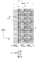
- FIG. 4 illustrates a method of transmitting an RS for measuring a channel according to a first embodiment provided by the present invention.
- the first embodiment provides a method of controlling RS transmission for measuring a channel by using information on a control channel for transmitting an uplink data channel.
- two carriers are scheduled on one uplink band.
- One carrier (hereinafter referred to as the first carrier) of the two carriers is used for transmitting uplink data and the other carrier (hereinafter referred to as the second carrier) is used for transmitting the DMRS for the sounding.
- the two carriers are simultaneously transmitted and such a simultaneous transmission corresponds to the type 1b transmission.
- the conventional uplink data channel is scheduled on the UE through a control channel 440 of a downlink band 430.
- Information on the control channel 440 includes resource allocation information of carriers which can be used in the uplink.
- the UE may transmit the data channels to scheduled frequency resource regions by determining whether the data channels are transmitted using one carrier 471 or using two carriers 472 and 474.
- the channel SRS based on the DMRS is transmitted.
- control channels scheduled like the data channels are required to schedule the channel SRSs, thereby reducing control channel capacity.
- the first embodiment provided by the present invention suggests a method of dynamically instructing the UE to use a predetermined carrier for the data transmission or only for the transmission of the RS for the sounding in the (downlink) control channel which can instruct the data transmission using two carriers.
- the first embodiment of the present invention does not reduce the capacity of the data channels and also does not reduce the data channel bandwidth since even though one of the two carriers is not used for the data channel, the bandwidth of the remaining carrier can be increased through scheduling.
- the BS may still use the method of indicating conventional type 0 and type 1a transmission according to the first embodiment of the present invention and also indicate type 1b transmission.
- the bandwidth for the sounding can be dynamically controlled, so that the required channels can be more accurately recognized.
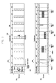
- FIG. 5 illustrates a method of configuring an uplink control channel for transmitting a reference signal for measuring a channel according to the first embodiment of the present invention.
- FIG. 5 shows a control channel for uplink data channel scheduling.
- the UE may recognize a plurality of control channel formats.
- the plurality of control channel formats there are two control channel formats for the uplink data channel transmission and the two control channel formats correspond to format #0/1A510 and format #4 520.
- format #0/1A 510 is a format which does not support MIMO
- format #4 520 is a format which does support MIMO.
- the two control channels include resource allocation information of the data channel and information on a transmission format of a transmitted transport block.
- format #4 520 scheduling information on a maximum of two transport blocks and MIMO precoding/precoder information are added for MIMO transmission.
- code resources used for the DMRS transmitted together with the data channel are indicated by Cyclic Shift (CS) indicators 532 and 542.
- the corresponding indicators inform of code resource information used for the DMRS.
- the BS may distinguish the channels of the respective UEs by using the code resources guaranteeing orthogonality through the code resource information.
- the type 0 transmission corresponds to the periodic transmission, so that the UE starts transmission when receiving the configuration information of type 0 from a higher layer without direct instruction from the control channel.
- the SRS transmission which can be indicated by the control channel corresponds to type 1a transmission.
- a 1-bit indicator 534 is used in format #0/1A
- a 2-bit indicator 544 is used in format #4 520.
- the BS instructs the UE to transmit the SRS.
- format #0/1A 510 using the 1 bit the SRS transmission of type 1a configured according to an indicator's command is performed.
- the BS may provide instructions for a total of four configurations for the transmission of type 1a and the respective configurations may have different transmission bandwidths and resources. Accordingly, based on an interpretation of the corresponding indicator 544, the type 1a transmission may be selectively performed.
- a first method of indicating the type 1b transmission by using the conventional control channel format interprets the control channel by using configuration information of type 1b.
- the UE When the UE is configured to enable the type 1b SRS transmission, the UE recognizes control channel resource allocations 530 and 540 as resource allocations using two carriers according to the existence or nonexistence of multi-cluster indications by multi-cluster indicators 536 and 546. In this circumstance, when SRS transmission 534 or 544 is triggered, the type 1b transmission is determined.
- the type 1a transmission is performed when the SRS transmission 534 or 544 is triggered when the transmission does not correspond to multi-cluster transmission.
- Format #0/1A 510 will be used as an example.
- the UE distinguishes resource allocation methods according to an indicator of a multi-cluster flag 536 of the control channel, the UE recognizes type 1b transmission when the multi-cluster flag is "1", indicating the use of two carriers, and SRS transmission 534 "1".
- the UE recognizes type 1a transmission when the multi-cluster flag is "0" and the SRS transmission 534 is "1".
- the resource allocation information 530 and 540 indicates a PRB region for two successive carriers.
- a method of identifying a carrier having a lower frequency or a carrier having a higher frequency to be used for the type 1b transmission or of informing, using higher layer signaling, which carrier is used for the type 1b transmission may be used.
- an indicator 544 for triggering the SRS transmission is configured by 2 bits
- the type 1b transmission is not performed if the 2 bits of the SRS transmission indicator 544 are "00”
- a low cluster is used for the SRS transmission and a high cluster is used for the data transmission if the 2 bits are "01”
- the low cluster is used for the data transmission and the high cluster is used for the SRS transmission if the 2 bits are "10”
- neither cluster is used or both clusters are used for the SRS transmission if the 2 bits are "11”.
- the multi-cluster flag is "0"
- the 2 bits of the SRS transmission 544 are used for the conventional type 1 a transmission.
- the type 1b transmission is performed only when the multi-cluster flag is "1" and the 2 bits of the SRS transmission indicator 544 are "11", and the remaining bit fields are used for the conventional type 1a transmission.
- information on which cluster is used for the SRS transmission follows the predefined rule or the higher layer signaling as described above.
- a second method of indicating type 1b transmission to the UE by using the conventional control channel format uses an additional indicator within the control channel.
- format #0/1A 510 since the downlink control channel and the uplink control channel use the same format, when the uplink uses regions which are used by the downlink, it does not cause capacity limitation. Furthermore, in format #4 520 corresponding to the format only for the uplink, the UE maintains the control channel reception capability like before, even though information on the control channel increases since the format is the format used for uplink MIMO transmission.
- One method using additional flag 550 adds one bit, while another method for using additional flag 550 adds 2 bits.
- the type 1a transmission is indicated if the additional 2-bit flag 550 is "00", the low cluster is used for the SRS transmission and the high cluster is used for the data transmission if the 2-bit flag 550 is "01”, the low cluster is used for the data transmission and the high cluster is used for the SRS transmission (or vice versa) if the 2-bit flag 550 is "10”, and neither cluster is used or both clusters are used for the SRS transmission if the 2-bit flag 550 is "11".
- the control channel scheduling the uplink data channel may indicate channel resource information of the DMRS used for the data channel through Cyclic Shift (CS) 532 or 542.
- the indicated value corresponds to a cyclic shift value used for a sequence of the DMSR. Since sequences using different cyclic shift values do not cause interference even though they are simultaneously transmitted and received, channel estimation and measurement are possible.
- the DMRS used for the transmission exists over two different clusters but the cyclic shift values actually used are the same.
- SPS Semi-Persistence Scheduling
- a value of the Cyclic Shift (CS) 532 or 542 is used only for the actual data channel and a value different from the value of CS 532 or 542 is used for the DMRS for the channel measurement, where the different value is not 0.
- the value may be configured by an offset of the value indicated by CS 532 or 542 through higher layer signaling or may indicate the actual cyclic shift value.
- the same number of DMRSs for the channel measurement as a number of DMRSs used for the data transmission is also transmitted through the same resource.
- a used cyclic shift value is indicated by higher layer signaling or an offset value of the indicated value is indicated by a higher layer, so that a conflict between different UEs can be prevented.
- the BS transmits precoder/precoding information 548 used for transmitting a plurality of DMRSs to the UE through the control channel 520.
- the UE pre-processes data symbols and then transmits the corresponding data channel.
- the same number of DMRSs used for the type 1b transmission as a number of DMRSs used for the data transmission is transmitted through the same resource, but a unitary precoder, not the indicated precoder, may be used.
- the BS measures the precoded channel.
- the BS measures a change channel by the precoder instead of an actual channel of the UE. Accordingly, the measurement of the channel has no meaning and is different from estimated channel information using the conventional SRS, so that the measurement is not reflected in the scheduling.
- the precoding information of the control channel is used for the data channel but is not used for the type 1b transmission. Further, in a case of transmission power, since the data channel and the SRS are time division multiplexed, all transmission power of the UE could be used for the SRS transmission.
- the RS for the channel measurement and the data channel are frequency division multiplexed. Accordingly, the transmission power of the UE is shared temporally between the DMRS used for the data channel and the DMRS used for the channel measurement.
- the transmission power of the UE is shared temporally between the DMRS used for the data channel and the DMRS used for the channel measurement.
- the present invention provides the following method as a method of controlling power for transmitting the channel SRS.
- power is first allocated for the DMRS used for the data channel and then power is allocated for the DMRS used for the channel measurement (and reduced as necessary).
- the same power as the power for the DMRS for the data channel is applied to the data symbol.
- the BS according to the first embodiment of the present invention transmits configuration information of type 1b SRS transmission to the UE enabling the type 1b SRS transmission to perform aperiodic uplink channel measurement by higher layer signaling. Further, the BS makes simultaneous transmission possible by frequency division multiplexing the data channel and the channel SRS.
- the first embodiment of the present invention does not influence and/or otherwise interfere with the conventional SRS transmission resources and does not reduce the SRS resources or the data channel capacity generated by the SRS transmission.
- the BS may measure the channel of the uplink bandwidth where the conventional SRS transmission cannot be performed and dynamically determine the band for the channel measurement.
- additional resources are not required to indicate the type of transmission and the BS may determine whether to perform transmission by using the control channel of the UE without higher layer signaling as necessary.
- FIG. 6 illustrates a method of transmitting an RS for measuring a channel according to a second embodiment provided by the present invention.
- a technology provided by the second embodiment of the present invention corresponds to a type 1b transmission method using location information of the control channel.
- a radio frame 610 consists of successive subframes 620.
- a location of type 1b transmission is determined by a logical location of the control channel which the BS transmits to the UE and a length of the bandwidth of the type 1b transmission is determined by a control channel amount of the control channel.
- the BS transmits the control channel to the UE by using a logical Control Channel Element (CCE) and may configure the control channel by using 1, 2, 4, 8, 16, or 32 successive CCEs according to a channel state of the UE.
- CCE logical Control Channel Element
- Transmitting the control channel to the UE by using a plurality of CCEs means that the channel state of the UE is not good, and accordingly, more resources are used to transmit the control channel at a lower transmission rate.
- the BS allocates different CCE regions to respective subframes by using a predetermined transmission pattern in order to prevent a conflict of the control channel region between the UEs. Accordingly, from the viewpoint of one UE, the UE searches for control channels allocated to itself in CCEs of different regions for respective subframes and recognizes by itself how many CCEs are used for the transmission.
- the UE derives a position of the resource for the type 1b transmission of the UE by using a lowest CCE of the control channel recognized by the UE and a transmission bandwidth of type 1b SRS transmission is transmitted in inverse proportion to a number of successively used CCEs.
- a large number of used CCEs means that the channel state of the UE is not good, and accordingly, the UE uses more power.
- the UE uses a large bandwidth for the type 1b transmission, more power is consumed and thus power per unit frequency is reduced, so that the BS has difficulty in performing the channel measurement.
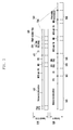
- FIG. 7 illustrates a relation between reference signal transmission for the channel measurement and control channel resource allocation according to the second embodiment provided by the present invention.
- reference numeral 710 indicates locations of CCEs and refers to transmission of the control channel using L successive CCEs based on a predetermined UE. After the UE recognizes the control channel, the UE configures a location indicating a transmission start point of the type 1b transmission and a bandwidth as described above as indicated by reference numeral 770 and performs the type 1b transmission on the uplink bandwidth as indicated by reference numeral 750.
- the second embodiment provided by the present invention has an advantage of triggering the type 1b transmission regardless of a type of the control channel. According to the provided second embodiment, the full uplink bandwidth may be uniformly used for the channel measurement due to a characteristic of different (random) start positions of the control channel for respective UEs.
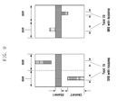
- FIG. 8 illustrates a method of transmitting an RS for measuring a channel according to a third embodiment of the present invention.
- the third embodiment provides a method of transmitting the data channel and the sounding RS through one carrier on the band contiguous with the uplink data channel by using uplink control information.
- the method of the third embodiment shown in FIG. 8 only increases a bandwidth of DMRS transmission in a signal transmitting one data channel cluster.
- the data channel uses the bandwidth scheduled by the control channel without any change.
- the bandwidth indicated by the data channel may be increased n times in a direction of a higher frequency index.
- the bandwidth does not necessarily have to be increased in the direction of the higher frequency index, and the bandwidth may be increased n times in a direction of a lower frequency index or the transmission bandwidth may be preset by higher layer signaling for the UE.
- FIG. 9 illustrates a method of transmitting an RS that supports hopping between slots in a method of transmitting an RS for measuring a channel according to a fourth embodiment of the present invention.
- the SRS transmission of type 0 and type 1a can be performed only once for a whole subframe duration.
- the SRS transmission using the DMRS can be performed using two slots existing in the subframe, two transmissions can be made.
- the DMRS does not have interference between UEs if the UEs use different cyclic shifts, so that the BS can receive the corresponding transmission even though the DMRS transmission of the UE hops between slots.
- the BS may measure the uplink band twice by only one channel SRS transmission instruction, and transmission efficiency may double in comparison with the type 0 and type 1a SRS transmissions.
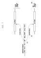
- FIG. 10 is a flowchart illustrating a method of operation for a BS to perform multi-cluster transmission on the channel SRS based on the aperiodic DMRS and the data channel in accordance with an embodiment of the present invention.
- the BS sets or establishes a type 1b transmission configuration corresponding to aperiodic channel SRS transmission for a UE, in accordance with an embodiment of the present invention.
- the BS transmits the type 1b configuration to the UE through higher layer signaling in step 1020.
- the BS indicates, through the control channel, that the UE is to perform type 1b transmission in accordance with embodiments of the present invention.
- the BS receives a channel SRS from the UE by using previously scheduled type 1b transmission information.
- the BS measures channel characteristics of the measured channel.
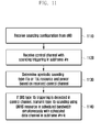
- FIG. 11 is a flowchart illustrating a method of operation for a UE to perform multi-cluster transmission on the channel SRS based on aperiodic DMRS and data channel, in accordance with an embodiment of the present invention.
- the UE receives configuration information for the channel SRS transmission from the BS in step 1110. Subsequently, the UE receives the control channel including scheduling information in which the SRS transmission is triggered at subframe #n in step 1120. In step 1130, the UE analyzes information on an aperiodic SRS type, resources, and power based on the received control channel.
- step 1140 when the UE detects the triggering of type 1b SRS transmission in the control channel, the UE transmits a type 1b SRS by using the DMRS resource at subframe #n+k.
- a channel and a data channel for the SRS are included in the detected control channel explicitly or implicitly.
- FIG. 12 is a block diagram illustrating an internal structure of a BS device for interference cancellation transmission in accordance with an embodiment of the present invention.
- a BS controller 1210 configures control channel information for simultaneously scheduling a sounding cluster and a data transmission cluster in the multi-cluster transmission in accordance with an embodiment of the present invention through a control channel information generator 1260 and transmits the configured control channel information to the UE. Further, the BS controller 1210 configures and transmits system information for type 1b SRS transmission to the UE. In addition, the BS controller 1210 selectively uses a channel estimator according to the channel measurement method which the BS provides to the UE, that is, type 0 transmission, type 1a transmission, and type 1b transmission.
- the BS controller 1210 When the type 0 transmission and the type 1a transmission are indicated to the UE, the BS controller 1210 performs the channel measurement by using an SRS channel estimator 1240. When the type 1b transmission is indicated to the UE, the BS controller 1210 selects channel information generated by a DMRS channel estimator 1250 through a selector 1220, transmits the selected channel information to a scheduler 1230, and uses the channel information for scheduling of the uplink data channel of the UE.
- the BS controller 1210 generates a control channel for uplink data channel transmission of the UE and transmits the generated control channel to the UE. Further, when the control channel includes information for aperiodic channel SRS transmission of the UE, the BS controller 1210 receives uplink data from the UE through a first carrier and the channel SRS through a second carrier, and controls to measure a channel state by using the received channel SRS.
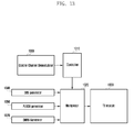
- FIG. 13 is a block diagram illustrating an internal structure of a UE device which transmits a channel SRS in accordance with an embodiment of the present invention.
- a UE controller 1310 recognizes control channel information of a control channel received from the BS through a control channel demodulator 1360.
- the UE configures a signal for transmitting an RS to measure an uplink channel by using the recognized control channel.
- the UE controller 1310 When the BS instructs the UE to transmit a channel SRS of type 1a, the UE controller 1310 generates a signal through an SRS generator 1340. In this circumstance, when there is data to be transmitted, the data and the data channel are time division multiplexed by a multiplexor 1320, and then transmitted to the BS by a transmission (TX) module 1330.
- TX transmission
- the UE controller 1310 When the BS instructs the UE to transmit the channel SRS of type 1b, the UE controller 1310 generates a data channel by using a data channel generator (PUSCH generator) 1350 and a DMRS generator 1370, controls the multiplexor 1320 to frequency division multiplex DMRSs for the data channel and the channel measurement by using resource allocation information indicated by the BS, and controls the TX module 1330 to transmit the DMRSs to the BS.
- PUSCH generator data channel generator
- DMRS generator 1370 controls the multiplexor 1320 to frequency division multiplex DMRSs for the data channel and the channel measurement by using resource allocation information indicated by the BS, and controls the TX module 1330 to transmit the DMRSs to the BS.
- the UE controller 1310 receives a control channel for uplink data channel transmission from the BS and determines whether the received control channel includes information for aperiodic channel SRS transmission.
- the control channel includes aperiodic channel SRS transmission information
- the UE controller 1310 controls the UE such that uplink data is transmitted through a first carrier and the channel SRS is transmitted through a second carrier.
- the UE controller 1310 determines whether to perform the aperiodic channel SRS transmission based on the multi-cluster flag indicating a number of uplink carriers and the SRS transmission indicator indicating SRS transmission trigger included in the control channel.
- Precoding information included in the control channel is used only for uplink data transmission and is not used for channel SRS transmission.
- the UE controller 1310 compares a sum of the power used for transmission of the RS for data channel demodulation and the power used for the channel SRS transmission with maximum transmission power of the UE. When the maximum transmission power is larger than the sum, the UE controller 1310 makes a setting such that the same power is used for both the transmission of the RS for the data channel demodulation and the transmission of the channel SRS. When the maximum transmission power is smaller than the sum, the UE first allocates power to the transmission of the RS of the data channel demodulation and then allocates power as required for the channel SRS transmission.
- the data channel and orthogonality are always maintained regardless of the existence of, and/or transmission on, the data channel of another UE within the same cell, and thus the data channel capacity of the other UEs in the cell can be maintained. Furthermore, embodiments of the present invention can be implemented on conventional systems without any substantial change since no additional information is needed on the control channel.
Landscapes
- Engineering & Computer Science (AREA)
- Signal Processing (AREA)
- Computer Networks & Wireless Communication (AREA)
- Mobile Radio Communication Systems (AREA)
Applications Claiming Priority (1)
| Application Number | Priority Date | Filing Date | Title |
|---|---|---|---|
| KR1020130013399A KR102004544B1 (ko) | 2013-02-06 | 2013-02-06 | 무선 통신 시스템에서 채널측정 기준신호 전송 방법 및 장치 |
Publications (3)
| Publication Number | Publication Date |
|---|---|
| EP2765732A2 true EP2765732A2 (fr) | 2014-08-13 |
| EP2765732A3 EP2765732A3 (fr) | 2014-12-24 |
| EP2765732B1 EP2765732B1 (fr) | 2019-09-04 |
Family
ID=50072916
Family Applications (1)
| Application Number | Title | Priority Date | Filing Date |
|---|---|---|---|
| EP14154125.0A Active EP2765732B1 (fr) | 2013-02-06 | 2014-02-06 | Transmission efficace de signaux de référence dans des systèmes de communication sans fil |
Country Status (4)
| Country | Link |
|---|---|
| US (1) | US9871629B2 (fr) |
| EP (1) | EP2765732B1 (fr) |
| KR (1) | KR102004544B1 (fr) |
| ES (1) | ES2752062T3 (fr) |
Cited By (4)
| Publication number | Priority date | Publication date | Assignee | Title |
|---|---|---|---|---|
| CN106998248A (zh) * | 2016-01-26 | 2017-08-01 | 中兴通讯股份有限公司 | 一种信号发送方法和用户设备 |
| WO2017193398A1 (fr) * | 2016-05-13 | 2017-11-16 | 华为技术有限公司 | Procédé et dispositif de commande de puissance |
| EP3343810A4 (fr) * | 2015-09-25 | 2018-09-19 | Huawei Technologies Co., Ltd. | Procédé de transmission de données, appareil de transmission de données, station de base et équipement utilisateur |
| EP3373688B1 (fr) * | 2015-11-27 | 2022-04-06 | Huawei Technologies Co., Ltd. | Procédé et dispositif de transmission de données |
Families Citing this family (15)
| Publication number | Priority date | Publication date | Assignee | Title |
|---|---|---|---|---|
| US9866290B2 (en) * | 2015-02-17 | 2018-01-09 | Newracom, Inc. | Apparatus and methods for multi-user simultaneous transmission |
| WO2016200093A1 (fr) * | 2015-06-07 | 2016-12-15 | 엘지전자 주식회사 | Procédé de réception ou de transmission d'un signal de référence de sondage pour une localisation dans un système de communication sans fil et appareil correspondant |
| US11646840B2 (en) * | 2016-05-13 | 2023-05-09 | Sony Corporation | Communications device, infrastructure equipment, wireless communications network and methods |
| WO2017209555A1 (fr) * | 2016-06-03 | 2017-12-07 | 엘지전자(주) | Procédé de transmission d'un canal de commande de liaison montante dans un système de communication sans fil, et dispositif associé |
| US10595315B2 (en) * | 2016-07-19 | 2020-03-17 | Qualcomm Incorporated | Enabling multi-cluster transmissions |
| CN107819557B (zh) * | 2016-09-13 | 2020-11-27 | 中国移动通信有限公司研究院 | 传输处理方法、网络侧设备及移动通信终端 |
| WO2018052351A1 (fr) * | 2016-09-19 | 2018-03-22 | Telefonaktiebolaget Lm Ericsson (Publ) | Premier dispositif de communication et procédés exécutés par celui-ci pour transmettre des signaux radio à l'aide d'une formation de faisceau à un deuxième dispositif de communication |
| WO2018056789A1 (fr) | 2016-09-26 | 2018-03-29 | 엘지전자(주) | Procédé de transmission/réception de liaison montante dans un système de communication sans fil, et dispositif associé |
| CN110419239B (zh) * | 2017-03-20 | 2024-05-07 | Oppo广东移动通信有限公司 | 无线通信方法和设备 |
| JP6918939B2 (ja) * | 2017-06-15 | 2021-08-11 | 株式会社Nttドコモ | ユーザ端末及び無線通信方法 |
| WO2019031951A1 (fr) * | 2017-08-11 | 2019-02-14 | 엘지전자 주식회사 | Procédé et dispositif de transmission ou de réception de signal sans fil dans un système de communication sans fil |
| EP3711266B1 (fr) | 2017-11-17 | 2022-06-15 | Telefonaktiebolaget LM Ericsson (Publ) | Systèmes et procédés relatifs à une émission de srs sélective en fréquence et à un précodage de pusch |
| CN114731257B (zh) * | 2020-01-10 | 2024-06-11 | 华为技术有限公司 | 上行信道解调方法和上行信道解调装置 |
| EP4264893B1 (fr) * | 2020-12-18 | 2025-10-08 | Telefonaktiebolaget LM Ericsson (publ) | Commande d'émission de signaux de référence |
| CN114666027B (zh) * | 2022-05-17 | 2022-08-19 | 深圳小米通讯技术有限公司 | 消息传输方法、装置、电子设备及可读存储介质 |
Family Cites Families (17)
| Publication number | Priority date | Publication date | Assignee | Title |
|---|---|---|---|---|
| EP2103017B1 (fr) * | 2007-03-29 | 2014-01-08 | LG Electronics Inc. | Procédé d'envoi d'un signal de référence dans un système de communication sans fil |
| KR20090015778A (ko) * | 2007-08-08 | 2009-02-12 | 엘지전자 주식회사 | 스케줄링 요청 신호 전송 방법 |
| CN201780605U (zh) * | 2009-04-22 | 2011-03-30 | 万信电子科技有限公司 | 服装试穿系统 |
| JP2011035785A (ja) * | 2009-08-04 | 2011-02-17 | Sharp Corp | 無線通信システム、移動局装置および基地局装置 |
| JP5538930B2 (ja) * | 2010-02-04 | 2014-07-02 | シャープ株式会社 | 移動局装置、基地局装置、無線通信システムおよび無線通信方法 |
| JP4913222B2 (ja) * | 2010-02-12 | 2012-04-11 | シャープ株式会社 | 無線通信システム、移動局装置、無線通信方法および集積回路 |
| JP4913221B2 (ja) * | 2010-02-12 | 2012-04-11 | シャープ株式会社 | 移動局装置、通信方法、集積回路、無線通信システムおよび制御プログラム |
| JP5132723B2 (ja) * | 2010-02-15 | 2013-01-30 | 株式会社エヌ・ティ・ティ・ドコモ | 参照信号送信方法、移動局装置及び基地局装置 |
| EP2552044A4 (fr) | 2010-03-22 | 2014-12-31 | Lg Electronics Inc | Procédé et équipement d'utilisateur pour la transmission d'informations de contrôle sur la liaison montante |
| CN101827444B (zh) * | 2010-03-31 | 2015-03-25 | 中兴通讯股份有限公司 | 一种测量参考信号的信令配置系统及方法 |
| CN102934382B (zh) * | 2010-06-04 | 2016-08-10 | Lg电子株式会社 | 控制探测参考信号发送的上行发送功率的方法和用户设备 |
| KR101719002B1 (ko) * | 2010-06-07 | 2017-03-23 | 엘지전자 주식회사 | 무선 통신 시스템에서 비주기적 사운딩 참조 신호 전송 방법 및 장치 |
| US9131457B2 (en) * | 2010-08-12 | 2015-09-08 | Samsung Electronics Co., Ltd. | Apparatus and method for transmission of uplink sounding reference signals in a wireless network |
| US9258092B2 (en) * | 2010-09-17 | 2016-02-09 | Blackberry Limited | Sounding reference signal transmission in carrier aggregation |
| JP4938123B1 (ja) * | 2010-10-04 | 2012-05-23 | 株式会社エヌ・ティ・ティ・ドコモ | 無線基地局装置、移動端末装置、無線通信方法及び無線通信システム |
| US9001780B2 (en) * | 2012-01-27 | 2015-04-07 | Qualcomm Incorporated | Physical layer issues related to multi-TA group support |
| US9210664B2 (en) * | 2012-04-17 | 2015-12-08 | Ofinno Technologies. LLC | Preamble transmission in a wireless device |
-
2013
- 2013-02-06 KR KR1020130013399A patent/KR102004544B1/ko active Active
-
2014
- 2014-02-06 ES ES14154125T patent/ES2752062T3/es active Active
- 2014-02-06 EP EP14154125.0A patent/EP2765732B1/fr active Active
- 2014-02-06 US US14/174,425 patent/US9871629B2/en active Active
Non-Patent Citations (1)
| Title |
|---|
| None |
Cited By (13)
| Publication number | Priority date | Publication date | Assignee | Title |
|---|---|---|---|---|
| EP3343810A4 (fr) * | 2015-09-25 | 2018-09-19 | Huawei Technologies Co., Ltd. | Procédé de transmission de données, appareil de transmission de données, station de base et équipement utilisateur |
| US10834715B2 (en) | 2015-09-25 | 2020-11-10 | Huawei Technologies Co., Ltd. | Performing selective scheduling on uplink frequencies using sounding reference signals (SRS) |
| EP3373688B1 (fr) * | 2015-11-27 | 2022-04-06 | Huawei Technologies Co., Ltd. | Procédé et dispositif de transmission de données |
| CN106998248B (zh) * | 2016-01-26 | 2020-09-15 | 中兴通讯股份有限公司 | 一种信号发送方法和用户设备 |
| CN106998248A (zh) * | 2016-01-26 | 2017-08-01 | 中兴通讯股份有限公司 | 一种信号发送方法和用户设备 |
| CN109640385A (zh) * | 2016-05-13 | 2019-04-16 | 华为技术有限公司 | 功率控制方法和装置 |
| CN109640385B (zh) * | 2016-05-13 | 2020-03-20 | 华为技术有限公司 | 功率控制方法和装置 |
| US10631249B2 (en) | 2016-05-13 | 2020-04-21 | Huawei Technologies Co., Ltd. | Power control method and apparatus |
| US10506520B2 (en) | 2016-05-13 | 2019-12-10 | Huawei Technologies Co., Ltd. | Power control method and apparatus |
| RU2701380C1 (ru) * | 2016-05-13 | 2019-09-26 | Хуавей Текнолоджиз Ко., Лтд. | Способ и устройство для управления мощностью |
| US11026179B2 (en) | 2016-05-13 | 2021-06-01 | Huawei Technologies Co., Ltd. | Power control method and apparatus |
| WO2017193398A1 (fr) * | 2016-05-13 | 2017-11-16 | 华为技术有限公司 | Procédé et dispositif de commande de puissance |
| US11419057B2 (en) | 2016-05-13 | 2022-08-16 | Huawei Technologies Co., Ltd. | Power control method and apparatus |
Also Published As
| Publication number | Publication date |
|---|---|
| KR20140100278A (ko) | 2014-08-14 |
| US20140219199A1 (en) | 2014-08-07 |
| ES2752062T3 (es) | 2020-04-02 |
| EP2765732A3 (fr) | 2014-12-24 |
| EP2765732B1 (fr) | 2019-09-04 |
| KR102004544B1 (ko) | 2019-07-26 |
| US9871629B2 (en) | 2018-01-16 |
Similar Documents
| Publication | Publication Date | Title |
|---|---|---|
| EP2765732B1 (fr) | Transmission efficace de signaux de référence dans des systèmes de communication sans fil | |
| EP2520118B1 (fr) | Mécanisme de sondage et configuration sous agrégation de porteuse | |
| RU2551899C2 (ru) | Устройство и способ для индентификации ресурсов формата 3 pucch | |
| CN106233658B (zh) | 在无线通信系统中发送探测参考信号的方法和终端 | |
| KR101923454B1 (ko) | 기계타입통신을 지원하는 무선 접속 시스템에서 사운딩 참조 신호 전송 방법 및 장치 | |
| US8817719B2 (en) | Methods and arrangements for dynamically triggering the transmission of sounding reference signal in a telecommunication system | |
| EP2293461B1 (fr) | Procédé de transmission et de réception d'un signal de référence de sondage de liaison montante, station de base, et terminal mobile | |
| CN105191185B (zh) | 用于自适应配置的时分双工通信系统的探测参考信号的传输 | |
| US9385849B2 (en) | Method and apparatus for transmitting and receiving a signal in a wireless communication system that supports plural component carriers | |
| US8837394B2 (en) | Sounding mechanism under carrier aggregation | |
| US10455565B2 (en) | Method and MTC device for receiving downlink control channel | |
| CN101867403B (zh) | 一种测量参考信号的多天线发送方法、终端 | |
| US9479304B2 (en) | Method for transceiving reference signal in wireless access system and terminal therefor | |
| EP2584731A2 (fr) | Procédé et appareil pour la transmission et la réception des informations de commande dans un système de communication sans fil | |
| CN102694637B (zh) | 时分双工系统下测量参考信号的发送方法及装置 | |
| CN102412880A (zh) | 多天线端口场景下的资源获取方法、配置方法及其设备 | |
| KR20170003597A (ko) | 비면허 대역을 지원하는 무선 접속 시스템에서 전송기회구간에 대한 채널상태정보를 보고하는 방법 및 이를 지원하는 장치 | |
| KR20170051410A (ko) | 비면허대역을 지원하는 무선접속시스템에서 채널상태측정 및 보고 방법 | |
| WO2018063084A1 (fr) | Commande de signalisation apériodique de srs pour systèmes sans fil | |
| AU2017334941B2 (en) | Reference signal design | |
| KR20170084111A (ko) | 비면허 대역을 지원하는 무선 접속 시스템에서 백오프 수행 방법 및 이를 지원하는 장치 | |
| EP3619897B1 (fr) | Transmission non continuée de signaux de référence de sondage en liaison montante | |
| JP7811662B2 (ja) | 異なるリソース密度を伴う基準信号 |
Legal Events
| Date | Code | Title | Description |
|---|---|---|---|
| PUAI | Public reference made under article 153(3) epc to a published international application that has entered the european phase |
Free format text: ORIGINAL CODE: 0009012 |
|
| 17P | Request for examination filed |
Effective date: 20140206 |
|
| AK | Designated contracting states |
Kind code of ref document: A2 Designated state(s): AL AT BE BG CH CY CZ DE DK EE ES FI FR GB GR HR HU IE IS IT LI LT LU LV MC MK MT NL NO PL PT RO RS SE SI SK SM TR |
|
| AX | Request for extension of the european patent |
Extension state: BA ME |
|
| PUAL | Search report despatched |
Free format text: ORIGINAL CODE: 0009013 |
|
| AK | Designated contracting states |
Kind code of ref document: A3 Designated state(s): AL AT BE BG CH CY CZ DE DK EE ES FI FR GB GR HR HU IE IS IT LI LT LU LV MC MK MT NL NO PL PT RO RS SE SI SK SM TR |
|
| AX | Request for extension of the european patent |
Extension state: BA ME |
|
| RIC1 | Information provided on ipc code assigned before grant |
Ipc: H04L 5/00 20060101AFI20141114BHEP |
|
| R17P | Request for examination filed (corrected) |
Effective date: 20150624 |
|
| RBV | Designated contracting states (corrected) |
Designated state(s): AL AT BE BG CH CY CZ DE DK EE ES FI FR GB GR HR HU IE IS IT LI LT LU LV MC MK MT NL NO PL PT RO RS SE SI SK SM TR |
|
| STAA | Information on the status of an ep patent application or granted ep patent |
Free format text: STATUS: EXAMINATION IS IN PROGRESS |
|
| 17Q | First examination report despatched |
Effective date: 20181114 |
|
| GRAJ | Information related to disapproval of communication of intention to grant by the applicant or resumption of examination proceedings by the epo deleted |
Free format text: ORIGINAL CODE: EPIDOSDIGR1 |
|
| GRAP | Despatch of communication of intention to grant a patent |
Free format text: ORIGINAL CODE: EPIDOSNIGR1 |
|
| GRAP | Despatch of communication of intention to grant a patent |
Free format text: ORIGINAL CODE: EPIDOSNIGR1 |
|
| STAA | Information on the status of an ep patent application or granted ep patent |
Free format text: STATUS: GRANT OF PATENT IS INTENDED |
|
| RAP1 | Party data changed (applicant data changed or rights of an application transferred) |
Owner name: NOKIA TECHNOLOGIES OY |
|
| INTG | Intention to grant announced |
Effective date: 20190515 |
|
| GRAS | Grant fee paid |
Free format text: ORIGINAL CODE: EPIDOSNIGR3 |
|
| GRAA | (expected) grant |
Free format text: ORIGINAL CODE: 0009210 |
|
| STAA | Information on the status of an ep patent application or granted ep patent |
Free format text: STATUS: THE PATENT HAS BEEN GRANTED |
|
| AK | Designated contracting states |
Kind code of ref document: B1 Designated state(s): AL AT BE BG CH CY CZ DE DK EE ES FI FR GB GR HR HU IE IS IT LI LT LU LV MC MK MT NL NO PL PT RO RS SE SI SK SM TR |
|
| RAP1 | Party data changed (applicant data changed or rights of an application transferred) |
Owner name: NOKIA TECHNOLOGIES OY |
|
| REG | Reference to a national code |
Ref country code: GB Ref legal event code: FG4D |
|
| REG | Reference to a national code |
Ref country code: CH Ref legal event code: EP |
|
| REG | Reference to a national code |
Ref country code: AT Ref legal event code: REF Ref document number: 1176875 Country of ref document: AT Kind code of ref document: T Effective date: 20190915 |
|
| REG | Reference to a national code |
Ref country code: DE Ref legal event code: R096 Ref document number: 602014052820 Country of ref document: DE |
|
| REG | Reference to a national code |
Ref country code: IE Ref legal event code: FG4D |
|
| REG | Reference to a national code |
Ref country code: NL Ref legal event code: FP |
|
| REG | Reference to a national code |
Ref country code: LT Ref legal event code: MG4D |
|
| PG25 | Lapsed in a contracting state [announced via postgrant information from national office to epo] |
Ref country code: BG Free format text: LAPSE BECAUSE OF FAILURE TO SUBMIT A TRANSLATION OF THE DESCRIPTION OR TO PAY THE FEE WITHIN THE PRESCRIBED TIME-LIMIT Effective date: 20191204 Ref country code: HR Free format text: LAPSE BECAUSE OF FAILURE TO SUBMIT A TRANSLATION OF THE DESCRIPTION OR TO PAY THE FEE WITHIN THE PRESCRIBED TIME-LIMIT Effective date: 20190904 Ref country code: LT Free format text: LAPSE BECAUSE OF FAILURE TO SUBMIT A TRANSLATION OF THE DESCRIPTION OR TO PAY THE FEE WITHIN THE PRESCRIBED TIME-LIMIT Effective date: 20190904 Ref country code: NO Free format text: LAPSE BECAUSE OF FAILURE TO SUBMIT A TRANSLATION OF THE DESCRIPTION OR TO PAY THE FEE WITHIN THE PRESCRIBED TIME-LIMIT Effective date: 20191204 Ref country code: FI Free format text: LAPSE BECAUSE OF FAILURE TO SUBMIT A TRANSLATION OF THE DESCRIPTION OR TO PAY THE FEE WITHIN THE PRESCRIBED TIME-LIMIT Effective date: 20190904 Ref country code: SE Free format text: LAPSE BECAUSE OF FAILURE TO SUBMIT A TRANSLATION OF THE DESCRIPTION OR TO PAY THE FEE WITHIN THE PRESCRIBED TIME-LIMIT Effective date: 20190904 |
|
| PG25 | Lapsed in a contracting state [announced via postgrant information from national office to epo] |
Ref country code: GR Free format text: LAPSE BECAUSE OF FAILURE TO SUBMIT A TRANSLATION OF THE DESCRIPTION OR TO PAY THE FEE WITHIN THE PRESCRIBED TIME-LIMIT Effective date: 20191205 Ref country code: RS Free format text: LAPSE BECAUSE OF FAILURE TO SUBMIT A TRANSLATION OF THE DESCRIPTION OR TO PAY THE FEE WITHIN THE PRESCRIBED TIME-LIMIT Effective date: 20190904 Ref country code: LV Free format text: LAPSE BECAUSE OF FAILURE TO SUBMIT A TRANSLATION OF THE DESCRIPTION OR TO PAY THE FEE WITHIN THE PRESCRIBED TIME-LIMIT Effective date: 20190904 Ref country code: AL Free format text: LAPSE BECAUSE OF FAILURE TO SUBMIT A TRANSLATION OF THE DESCRIPTION OR TO PAY THE FEE WITHIN THE PRESCRIBED TIME-LIMIT Effective date: 20190904 |
|
| REG | Reference to a national code |
Ref country code: AT Ref legal event code: MK05 Ref document number: 1176875 Country of ref document: AT Kind code of ref document: T Effective date: 20190904 |
|
| REG | Reference to a national code |
Ref country code: ES Ref legal event code: FG2A Ref document number: 2752062 Country of ref document: ES Kind code of ref document: T3 Effective date: 20200402 |
|
| PG25 | Lapsed in a contracting state [announced via postgrant information from national office to epo] |
Ref country code: RO Free format text: LAPSE BECAUSE OF FAILURE TO SUBMIT A TRANSLATION OF THE DESCRIPTION OR TO PAY THE FEE WITHIN THE PRESCRIBED TIME-LIMIT Effective date: 20190904 Ref country code: EE Free format text: LAPSE BECAUSE OF FAILURE TO SUBMIT A TRANSLATION OF THE DESCRIPTION OR TO PAY THE FEE WITHIN THE PRESCRIBED TIME-LIMIT Effective date: 20190904 Ref country code: AT Free format text: LAPSE BECAUSE OF FAILURE TO SUBMIT A TRANSLATION OF THE DESCRIPTION OR TO PAY THE FEE WITHIN THE PRESCRIBED TIME-LIMIT Effective date: 20190904 Ref country code: PT Free format text: LAPSE BECAUSE OF FAILURE TO SUBMIT A TRANSLATION OF THE DESCRIPTION OR TO PAY THE FEE WITHIN THE PRESCRIBED TIME-LIMIT Effective date: 20200106 Ref country code: PL Free format text: LAPSE BECAUSE OF FAILURE TO SUBMIT A TRANSLATION OF THE DESCRIPTION OR TO PAY THE FEE WITHIN THE PRESCRIBED TIME-LIMIT Effective date: 20190904 |
|
| PG25 | Lapsed in a contracting state [announced via postgrant information from national office to epo] |
Ref country code: CZ Free format text: LAPSE BECAUSE OF FAILURE TO SUBMIT A TRANSLATION OF THE DESCRIPTION OR TO PAY THE FEE WITHIN THE PRESCRIBED TIME-LIMIT Effective date: 20190904 Ref country code: SK Free format text: LAPSE BECAUSE OF FAILURE TO SUBMIT A TRANSLATION OF THE DESCRIPTION OR TO PAY THE FEE WITHIN THE PRESCRIBED TIME-LIMIT Effective date: 20190904 Ref country code: IS Free format text: LAPSE BECAUSE OF FAILURE TO SUBMIT A TRANSLATION OF THE DESCRIPTION OR TO PAY THE FEE WITHIN THE PRESCRIBED TIME-LIMIT Effective date: 20200224 Ref country code: SM Free format text: LAPSE BECAUSE OF FAILURE TO SUBMIT A TRANSLATION OF THE DESCRIPTION OR TO PAY THE FEE WITHIN THE PRESCRIBED TIME-LIMIT Effective date: 20190904 |
|
| REG | Reference to a national code |
Ref country code: DE Ref legal event code: R097 Ref document number: 602014052820 Country of ref document: DE |
|
| PLBE | No opposition filed within time limit |
Free format text: ORIGINAL CODE: 0009261 |
|
| STAA | Information on the status of an ep patent application or granted ep patent |
Free format text: STATUS: NO OPPOSITION FILED WITHIN TIME LIMIT |
|
| PG2D | Information on lapse in contracting state deleted |
Ref country code: IS |
|
| PG25 | Lapsed in a contracting state [announced via postgrant information from national office to epo] |
Ref country code: DK Free format text: LAPSE BECAUSE OF FAILURE TO SUBMIT A TRANSLATION OF THE DESCRIPTION OR TO PAY THE FEE WITHIN THE PRESCRIBED TIME-LIMIT Effective date: 20190904 Ref country code: IS Free format text: LAPSE BECAUSE OF FAILURE TO SUBMIT A TRANSLATION OF THE DESCRIPTION OR TO PAY THE FEE WITHIN THE PRESCRIBED TIME-LIMIT Effective date: 20200105 |
|
| 26N | No opposition filed |
Effective date: 20200605 |
|
| PG25 | Lapsed in a contracting state [announced via postgrant information from national office to epo] |
Ref country code: SI Free format text: LAPSE BECAUSE OF FAILURE TO SUBMIT A TRANSLATION OF THE DESCRIPTION OR TO PAY THE FEE WITHIN THE PRESCRIBED TIME-LIMIT Effective date: 20190904 |
|
| REG | Reference to a national code |
Ref country code: CH Ref legal event code: PL |
|
| REG | Reference to a national code |
Ref country code: BE Ref legal event code: MM Effective date: 20200229 |
|
| PG25 | Lapsed in a contracting state [announced via postgrant information from national office to epo] |
Ref country code: LU Free format text: LAPSE BECAUSE OF NON-PAYMENT OF DUE FEES Effective date: 20200206 Ref country code: MC Free format text: LAPSE BECAUSE OF FAILURE TO SUBMIT A TRANSLATION OF THE DESCRIPTION OR TO PAY THE FEE WITHIN THE PRESCRIBED TIME-LIMIT Effective date: 20190904 |
|
| PG25 | Lapsed in a contracting state [announced via postgrant information from national office to epo] |
Ref country code: LI Free format text: LAPSE BECAUSE OF NON-PAYMENT OF DUE FEES Effective date: 20200229 Ref country code: CH Free format text: LAPSE BECAUSE OF NON-PAYMENT OF DUE FEES Effective date: 20200229 |
|
| PG25 | Lapsed in a contracting state [announced via postgrant information from national office to epo] |
Ref country code: BE Free format text: LAPSE BECAUSE OF NON-PAYMENT OF DUE FEES Effective date: 20200229 |
|
| PG25 | Lapsed in a contracting state [announced via postgrant information from national office to epo] |
Ref country code: MT Free format text: LAPSE BECAUSE OF FAILURE TO SUBMIT A TRANSLATION OF THE DESCRIPTION OR TO PAY THE FEE WITHIN THE PRESCRIBED TIME-LIMIT Effective date: 20190904 Ref country code: CY Free format text: LAPSE BECAUSE OF FAILURE TO SUBMIT A TRANSLATION OF THE DESCRIPTION OR TO PAY THE FEE WITHIN THE PRESCRIBED TIME-LIMIT Effective date: 20190904 |
|
| PG25 | Lapsed in a contracting state [announced via postgrant information from national office to epo] |
Ref country code: MK Free format text: LAPSE BECAUSE OF FAILURE TO SUBMIT A TRANSLATION OF THE DESCRIPTION OR TO PAY THE FEE WITHIN THE PRESCRIBED TIME-LIMIT Effective date: 20190904 |
|
| PGFP | Annual fee paid to national office [announced via postgrant information from national office to epo] |
Ref country code: FR Payment date: 20251231 Year of fee payment: 13 |
|
| PGFP | Annual fee paid to national office [announced via postgrant information from national office to epo] |
Ref country code: NL Payment date: 20260106 Year of fee payment: 13 |
|
| PGFP | Annual fee paid to national office [announced via postgrant information from national office to epo] |
Ref country code: GB Payment date: 20260106 Year of fee payment: 13 |
|
| PGFP | Annual fee paid to national office [announced via postgrant information from national office to epo] |
Ref country code: ES Payment date: 20260305 Year of fee payment: 13 |
|
| PGFP | Annual fee paid to national office [announced via postgrant information from national office to epo] |
Ref country code: IE Payment date: 20260102 Year of fee payment: 13 Ref country code: DE Payment date: 20251230 Year of fee payment: 13 |
|
| PGFP | Annual fee paid to national office [announced via postgrant information from national office to epo] |
Ref country code: IT Payment date: 20260122 Year of fee payment: 13 |
|
| PGFP | Annual fee paid to national office [announced via postgrant information from national office to epo] |
Ref country code: TR Payment date: 20260203 Year of fee payment: 13 |