EP2765896B1 - Lave-vaisselle pourvu d'au moins une source de lumière commandée en fonction de la position d'un panier de réception mobile - Google Patents
Lave-vaisselle pourvu d'au moins une source de lumière commandée en fonction de la position d'un panier de réception mobile Download PDFInfo
- Publication number
- EP2765896B1 EP2765896B1 EP12780129.8A EP12780129A EP2765896B1 EP 2765896 B1 EP2765896 B1 EP 2765896B1 EP 12780129 A EP12780129 A EP 12780129A EP 2765896 B1 EP2765896 B1 EP 2765896B1
- Authority
- EP
- European Patent Office
- Prior art keywords
- door
- light sources
- light source
- dishwasher
- dishwasher according
- Prior art date
- Legal status (The legal status is an assumption and is not a legal conclusion. Google has not performed a legal analysis and makes no representation as to the accuracy of the status listed.)
- Active
Links
Images



Classifications
-
- A—HUMAN NECESSITIES
- A47—FURNITURE; DOMESTIC ARTICLES OR APPLIANCES; COFFEE MILLS; SPICE MILLS; SUCTION CLEANERS IN GENERAL
- A47L—DOMESTIC WASHING OR CLEANING; SUCTION CLEANERS IN GENERAL
- A47L15/00—Washing or rinsing machines for crockery or tableware
- A47L15/42—Details
- A47L15/4293—Arrangements for programme selection, e.g. control panels; Indication of the selected programme, programme progress or other parameters of the programme, e.g. by using display panels
-
- A—HUMAN NECESSITIES
- A47—FURNITURE; DOMESTIC ARTICLES OR APPLIANCES; COFFEE MILLS; SPICE MILLS; SUCTION CLEANERS IN GENERAL
- A47L—DOMESTIC WASHING OR CLEANING; SUCTION CLEANERS IN GENERAL
- A47L15/00—Washing or rinsing machines for crockery or tableware
- A47L15/0018—Controlling processes, i.e. processes to control the operation of the machine characterised by the purpose or target of the control
- A47L15/0049—Detection or prevention of malfunction, including accident prevention
-
- A—HUMAN NECESSITIES
- A47—FURNITURE; DOMESTIC ARTICLES OR APPLIANCES; COFFEE MILLS; SPICE MILLS; SUCTION CLEANERS IN GENERAL
- A47L—DOMESTIC WASHING OR CLEANING; SUCTION CLEANERS IN GENERAL
- A47L15/00—Washing or rinsing machines for crockery or tableware
- A47L15/42—Details
- A47L15/4251—Details of the casing
- A47L15/4257—Details of the loading door
-
- A—HUMAN NECESSITIES
- A47—FURNITURE; DOMESTIC ARTICLES OR APPLIANCES; COFFEE MILLS; SPICE MILLS; SUCTION CLEANERS IN GENERAL
- A47L—DOMESTIC WASHING OR CLEANING; SUCTION CLEANERS IN GENERAL
- A47L15/00—Washing or rinsing machines for crockery or tableware
- A47L15/42—Details
- A47L15/50—Racks ; Baskets
-
- A—HUMAN NECESSITIES
- A47—FURNITURE; DOMESTIC ARTICLES OR APPLIANCES; COFFEE MILLS; SPICE MILLS; SUCTION CLEANERS IN GENERAL
- A47L—DOMESTIC WASHING OR CLEANING; SUCTION CLEANERS IN GENERAL
- A47L15/00—Washing or rinsing machines for crockery or tableware
- A47L15/42—Details
- A47L15/50—Racks ; Baskets
- A47L15/507—Arrangements for extracting racks, e.g. roller supports
-
- A—HUMAN NECESSITIES
- A47—FURNITURE; DOMESTIC ARTICLES OR APPLIANCES; COFFEE MILLS; SPICE MILLS; SUCTION CLEANERS IN GENERAL
- A47L—DOMESTIC WASHING OR CLEANING; SUCTION CLEANERS IN GENERAL
- A47L2401/00—Automatic detection in controlling methods of washing or rinsing machines for crockery or tableware, e.g. information provided by sensors entered into controlling devices
- A47L2401/34—Other automatic detections
-
- A—HUMAN NECESSITIES
- A47—FURNITURE; DOMESTIC ARTICLES OR APPLIANCES; COFFEE MILLS; SPICE MILLS; SUCTION CLEANERS IN GENERAL
- A47L—DOMESTIC WASHING OR CLEANING; SUCTION CLEANERS IN GENERAL
- A47L2501/00—Output in controlling method of washing or rinsing machines for crockery or tableware, i.e. quantities or components controlled, or actions performed by the controlling device executing the controlling method
- A47L2501/26—Indication or alarm to the controlling device or to the user
Definitions
- the invention relates to a dishwasher, in particular domestic dishwasher, with a one, in particular front, loading port having rinse tank, the loading opening occlusive door and at least one out of the washing and in this movable into receiving basket for items to be washed.
- Dishwashers often have visual displays which are intended to facilitate operation, for example by prompting them to perform certain operations, for example to replenish salt in a regeneration salt container.
- visual displays may e.g. be provided on a door front panel, on the upper edge of the door, on the inner wall of the door and / or in the washing.
- the US 2010/0126526 A1 only concerns a safety precaution against the putting into service of a dishwasher when a child is trapped in their rinsing container. If a "rack sensing component 130", ie dish basket detection component, detects that a dish rack such as lower basket 110 of the dishwasher is not completely in the washing compartment in its washing position or "washing location 104" but has been moved out of it, it generates a signal the processing unit 126 of a control device 122, which then prevents the washing operation of the dishwasher.
- a "user interface 124" associated with the processing unit provides an indication that the crockery basket is not in its washing position or is rendered inoperative.
- the US 5,257,171 refers only to an electric control apparatus 20 (see FIG. 2 ), which controls the various washing steps of a dishwasher and the user displays this washing operation of the dishwasher via an indicator lamp "indication lamp”.
- the object of the invention is to propose a dishwasher of the aforementioned type, which is improved with regard to the operation of at least one receiving basket for items to be washed.
- Dishwasher in particular domestic dishwasher, with a one, in particular front loading, having a loading container, the loading opening occlusive door and at least one out of the washing out and in this movable receiving basket for items to be washed
- said Dishwasher a, in particular non-contact, means for detecting at least one movement position of the receiving basket and a control device which controls at least one arranged in and / or on the dishwasher light source in response to the at least one movement position of the receiving basket, and wherein an elongated light source or more Light sources along a provided for the respective receiving basket, in particular for a lower basket, in the washing and / or on the inner wall surface of the door Füh are provided.
- Such an embodiment opens up completely new possibilities for optically based user support and user guidance, in particular user animation.
- the user can be made aware, for example, by lighting up a light source, that the receiving basket was not moved completely into the washing container, for example, after being loaded with items to be washed. In this way, it can be prevented that the door bounces against the receiving basket when closing and thereby wicks items from its holder and is damaged.
- a similar situation is also given when extending the receiving basket when it is driven at too high a speed in its outer end position. Because even this could be washed dishes.
- the proposed embodiment offers the possibility of optically simulating the progress of the extension and retraction of the receiving basket and display.
- the control device is expediently designed such that at least one parameter of the at least one light source can be controlled by the control device, in particular its illuminance, color, lighting mode, switching on and / or off time, and / or timing can be varied.
- a change in the respective spatial position of the respective receiving basket can be signaled or displayed dynamically by a change in at least one parameter of the one or more light sources.
- a parameter of a light source which can be controlled as a function of the respective movement position of the receiving basket is thus, for example, its operating state, ie the light source can simply be switched on or lit up in order to make the user aware of a certain movement position of the receiving cage.
- an indication of the respective movement position of the receiving basket can take place in that the illuminance or the color of a light source is changed.
- a color change the use of color filters is conceivable or light sources are provided which have illumination means, such as LEDs of different colors, whereby a specific illumination means or - to generate a mixed color - a plurality of illumination means are activated.
- a non-contact device for the position detection of the respective receiving basket, a complex adaptation of the respective receiving basket is not required, so that receiving baskets can be maintained unchanged with previous design and storage.
- the non-contact device for position detection can, for example, work inductively or capacitively and use corresponding sensors.
- a Hall sensor is used, wherein the receiving basket at least one cooperating with said sensor magnet is mounted.
- the at least one light source is expediently arranged outside the respective receiving basket in and / or on the dishwasher and can be varied as a function of the at least one movement position of the receiving basket.
- the respective light source is provided in the washing container, preferably in and / or at its bottom and / or its side walls, and / or provided on the inner wall surface of the door guideway, wherein the inner surface of the door faces in its final closed position the treatment interior of the washing compartment.
- the control device in the case of a plurality of light sources, is configured such that it controls an increasing number of light sources as the travel path of the receiving basket increases.
- the light sources can be controlled by the control device so that increases the number of illuminated light sources in the extension of the receiving basket and reduced in the retraction direction.
- the row formed by the light sources or a light strip thus extends in the extension direction and shortens in the retraction direction.
- the length of the light strip or the light source row remains the same during the retraction or extension movement of the receiving basket, but that the light strip or the light source row changes or changes its color as a function of the progress of the retraction or withdrawal movement of the receiving basket luminous, for example, colored portion of the light strip according to the Move the basket up or down.
- an elongated light source such as an actively illuminated light strip may be provided, which is formed for example by one or more LED or OLED lighting elements.
- the guideways are usually formed by telescopic extensions, so that the receiving basket can be sufficiently far out of the washing out.
- receiving a telescopic extension is not required because the receiving basket can be supported on the door or on an inner side forming the inner door wall.
- the receiving basket is provided in this case usually with underside rollers or sliding elements, which cooperate with in the direction of movement of the receiving basket extending running surfaces on the (in the Endschbachritt ein the door facing the interior of the washing) door inner wall. Also within the washing tub running surfaces are present, which are present for example at the bottom of the washing.
- a row of light sources or a light band is then preferably positioned directly on the tread.
- the light sources are preferably recessed, for example, in recesses, arranged so that the rollers or sliding elements can move largely disability-free along the tread.
- a further advantageous measure to detect the progress of the extension and retraction movement of the receiving basket based on the light strip is that the control device is designed so that it controls the arranged in a row, a plurality of light sources so that the change of a parameter of Transmitted light sources in the direction of movement of the receiving basket. It is advantageous if the control of the multiple light sources takes place such that the parameter with a the speed of movement of the receiving basket corresponding speed propagates.
- a light source on the inside of the treatment chamber facing a side wall and / or bottom wall of the washing and / or on the in the final closing position of the door to the treatment room of the washing container facing inside of the inner door wall be applied spreading.
- a breakthrough or a recess receiving the light source can also be present in said walls.
- a preferred variant provides for the case of an arrangement of one or more light sources on the door, that at least a portion of the door inner wall, preferably the entire door inner wall, is translucent, that is, consists of one or more light-transmitting materials.
- One or more light sources are then arranged in one or more of the light-transmissive portion or of the total translucent door inner wall covered recesses or openings of the door.
- One or more light sources can thus be expediently arranged in one or more recesses or openings behind a light-permeable cover element, such as a glass and / or plastic material, which forms a partial surface area of the otherwise made of an opaque material such as metal, especially stainless steel door inner wall.
- a light-permeable cover element such as a glass and / or plastic material, which forms a partial surface area of the otherwise made of an opaque material such as metal, especially stainless steel door inner wall.
- a completely translucent designed door inner wall light sources inside the door below the inner door wall, which faces the treatment room of the washing container in the final closing position of the door, be arranged without causing gaps between the light source and the inner door wall, which hold the danger in itself that during operation of the dishwasher rinse enters the door.
- the subarea or door inner wall is provided on the outside or inside with a coating which has a lower light transmittance than that of the subarea or door inner wall forming material.
- An over the or the light sources The area located on the other hand remains uncoated, so that a window is formed through which the light from the light sources can pass outwards.
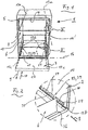
- Dishwasher 1 shown in its entirety comprises a washing container 2 which preferably has a front loading opening 4 which can be closed by a door 3. Furthermore, the dishwasher 1 comprises a plurality of baskets for items such as crockery and cutlery, wherein in the figures dishwashing machines 1 with two receptacles, namely an upper receptacle 5 and a lower receptacle 6, are shown by way of example.
- the receiving baskets 5, 6 are held displaceably in a substantially horizontally extending movement direction 8 and can be moved out of the rinsing container 2 in an extension direction 9 and into the rinsing container 2 in a retraction direction 10.
- the receiving baskets 5, 6 are guided on guideways, which extend in the direction of movement 8.
- the upper receiving basket 5 is guided on two lateral, on the side walls 14, 14 'of the washing container 2 arranged guideways 13 a, which in the Fig. 1 . 4 and 5 are indicated by dashed lines.
- the two guide tracks 13a one of which is arranged on the one side wall 14 and the other on the opposite side wall 14 'of the washing container 2, for example, by telescopic extensions (not shown) formed so that the upper receiving basket 5 almost completely from the washing 2 moved out, in particular, is mobile.
- each existing guide rail 13b continues in a on the inner wall surface, ie inside 17 of the door 3, which is assigned to the treatment room of the washing in the final closing position of the door, extending in the direction of movement 8 guide track 13c .
- the guideways 13b and 13c are in Fig. 4 and 5 also shown by dashed lines. They run along the two lateral edge zones of the door approximately parallel to their longitudinal sides, which are in the approximately horizontal opening end position of the door in the depth direction of the dishwasher extend.
- the dishwasher 1 further comprises a, in particular non-contact, means 18 for detecting at least one, preferably a plurality of movement positions of the receiving baskets 5, 6, which in Fig. 3 by way of example for the case of a lower receiving basket 6 is shown.
- a device 18 of the type mentioned a variety of design options available.
- it may be an inductively or capacitively operating device.
- a device 19 is provided which operates on the basis of the Hall effect. It accordingly comprises a Hall sensor 19, which is mounted on the inside of a side wall 14, 14 'or is embedded in a recess 20 of a side wall.
- the device 18 comprises at least one magnet, but preferably a plurality of magnets 23 distributed over the depth of the receiving baskets 5, 6.
- the magnets 23 are laterally fixed to the receiving baskets 5, 6, for example on a basket wire 24 extending in the direction of movement 8, so that they reach the effective range of the Hall sensor 19 during basket movement. It is also conceivable that only one magnet 23 on the receiving baskets 5, 6 but several along a guideway 13 distributed Hall sensors 19 or more Hall sensors and a plurality of magnets 23 are present.
- the Hall sensor or sensors 19 are connected via a signal line 25 to a control device 26, with which a parameter of at least one arranged outside the receiving baskets 5, 6 in and / or on the dishwasher light source 27 is variable depending on the respective movement position of a receiving basket ,
- a control device 26 with which a parameter of at least one arranged outside the receiving baskets 5, 6 in and / or on the dishwasher light source 27 is variable depending on the respective movement position of a receiving basket ,
- the light sources it should generally be said that they are illustrated very simply in the drawings and that they are to be understood as meaning lighting elements which may comprise one or more illumination means such as LEDs and optionally further components such as housings and optical elements.
- a plurality of light sources 27 are connected via one or more control lines 21 (in FIG Fig. 3 For reasons of simplification, only a single control line is shown) connected to the control device 26.
- Control devices that can be used for the tax task in question are well known, so that explanations on the design at this point unnecessary.
- a control device usually present in dishwashers, with which the program sequences etc. are controlled, ie controlled, can be used for the stated purpose, if appropriate after appropriate adaptation.
- light sources 27 can be controlled so that a parameter of the light sources changes depending on the movement position of a receiving basket, for example, the operating state (on, off), the illuminance, and / or the light color.
- the above-described danger that dishware dissolves in a too violent attack of a receiving basket to its final position and thereby possibly damaged, can be at least reduced.
- Another way of identifying the VerfahrSches amitkorbes is that in addition to or in addition to the illuminance, the color of the light sources is changed. This can be accomplished, for example, by a light source comprising a plurality of light sources, such as LEDs of different colors, wherein different light colors can be generated by activating one or more light sources, for example by means of a color mixture.
- the number of light sources 27 controlled by the control device can be varied or changed.
- a further advantageous embodiment provides that a plurality of light sources 27, for example, as in Fig. 4 shown in the form of transversely to the direction of movement 8 extending bands 44 may be formed in a direction of movement 8 extending row 29 are arranged. If the distances 30 ( Fig. 2 ) are relatively small between the light sources 27 or no distances between them are present, arises in the direction of movement 8 extending light or light band 33.
- the rows 29 and light bands 33 are at the treatment room the wash compartment facing side walls 14, 14 'of the washing compartment 2 or on the inside of the door completely closed door facing the treatment room 17 of the door 3 on the inside overlapping door inner wall 34 is arranged.
- a row 29 of light sources 27 and / or a light band 33 can, for example, be controlled by the control device 26 in such a way that the number of illuminated light sources 27 in the extension direction 9 of the receiving baskets 5, 6 increases and is reduced in the retraction direction 10.
- a user then also identifies the respective travel state of a receiving basket 5, 6 and in particular also the end position in the fully extended or fully retracted position on the basis of the length of the illuminated light or light band 33 or on the length of a row 29 of light sources. It is expedient if a luminous or light band 33 or a row of light sources has a length 31 (FIG. Fig. 5 ), which corresponds to the maximum possible travel distance of the receiving basket 5, 6.
- a light strip 33 is, in order to emphasize the movement planes of the receiving baskets 5, 6, arranged in the immediate vicinity of a guide track 13 on a side wall 14, 14 'or on the inside 17 of the door 3. In the case of the lowerrackorbes 6 this is not performed on a telescopic extension, but there are rollers 35 or similar guide elements on the receiving basket 6, which cooperate with a arranged on the inside 17 of the door 3 and the bottom 36 of the washing compartment 2 tread 37.
- Fig. 3 is such a tread 37, which is formed by a side strip of the bottom 36 of the washing container 2 shown.
- a tread 37 for example, the in Fig. 3 Running surface shown, may be provided with one or more light sources 27, which are arranged in the form of a extending in the direction of movement 8 series 29 or a light or light band 33.
- a light source 27 may in principle be placed on the surface of a side wall 14 or on the surface of the door inner wall 34, projecting from this raised (not shown).
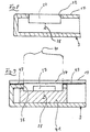
- a light source 27 is in a recess or aperture 32 of the respective wall, such as in FIG Fig. 3 and Fig. 8 shown, so that it is largely flush with the surface of the wall.
- the light sources 27 can be arranged in a recess 38 of the door 3 and optionally be held by a carrier 41, wherein the recess 38 is covered by the door inner wall 34 formed from one or more light-transmitting materials ( Fig. 9 ).
- the light sources 27 thus sit inside the door behind the translucent door inner wall 34.
- a portion 39 of the door inner wall 34 is translucent ( Fig. 10 ).
- the door inner wall 34 has two, in the direction of movement 8 of the respective receiving basket 5, 6 (which runs approximately parallel to the depth extent of the washing compartment), projecting raised edge webs 45, which by a also designed connecting web 46 are connected to each other near the upper edge of the door 3.
- a light strip 33 is arranged, wherein the light bands 33 and the edge webs 45 carrying them are each flanked on the outside by a guide track 13c, which is designed as a running surface 37
- Luminous bands 33 also extend in the direction of movement 8, wherein the light bands 33 are embedded in the inside 17 of the door 13 or, as in Fig. 9 and Fig. 10 shown are arranged.
- the light bands 33 extend within the running surfaces 37, with which the lower receiving basket 6, for example via rollers 35 cooperates.
- lighting or light bands or rows of several light sources or lighting sources are provided both in the region of the bottom 36 of the washing container 2 and in the region of the inside 17 of the door inner wall 34, in particular in the region of the two guide tracks 13b and 13c of the lower receiving basket, such as 6, are provided which roll its rollers 35 out of or out of the washing container when being moved out.
- the total possible total travel path of the lower receiving basket can be made visually recognizable to the respective user.
- the light sources can expediently be provided either on top of the floor 36 and / or on top of the inside 17 of the door inner wall 34, or in recesses or openings of the bottom 36 and / or the door inner wall 34.
- the recesses or openings may expediently be provided on each side with a translucent cover.
- This translucent cover is preferably mounted substantially flush with respect to the respective recess or the respective opening surrounding opaque areas of the floor and / or the door inner wall.
- the one or more light sources can also be arranged below the bottom of the washing container and / or below the door inner wall (in the closing end position of the door) facing the interior of the washing container, if the entire inner wall of the washing container bottom and / or the entire inner door wall in each case in particular consist of a translucent Material exists or exists.
- LEDs or OLEDs but also other lighting or lighting means can be used as light sources for the above-described, different design variants, as long as at least one parameter of the respective lighting or lighting means such as its on and / or off, luminous intensity, Control brightness, color, timing, ... etc. by means of a conventional control device, that can influence and change.
Landscapes
- Washing And Drying Of Tableware (AREA)
Claims (16)
- Lave-vaisselle (1), notamment lave-vaisselle ménager comprenant une cuve de lavage (2) comportant une ouverture de chargement (4), notamment du côté avant, une porte (3) fermant l'ouverture de chargement (4) et au moins un panier de réception (5, 6) de vaisselle déplaçable hors de ou vers l'intérieur de la cuve de lavage (2),
dans lequel le lave-vaisselle (1) comprend un dispositif (18), fonctionnant notamment sans contact, pour détecter au moins une position de déplacement du panier de réception (5, 6) et un moyen de commande (26) qui commande au moins une source lumineuse (27) disposée dans et/ou sur le lave-vaisselle (1) en fonction de la au moins une position de déplacement du panier de réception (5, 6),
caractérisé en ce qu'une source lumineuse allongée (33) ou plusieurs sources lumineuses (27) sont disposées le long d'une voie de guidage (13a, 13b, 13c) prévue pour le panier de réception respectif (5, 6), notamment pour un panier de réception inférieur (6), dans la cuve de lavage (2) et/ou sur la surface de paroi intérieure (17) de la porte (2). - Lave-vaisselle selon la revendication 1, caractérisé en ce que la au moins une source lumineuse (27) est disposée à l'extérieur du panier de réception respectif (5, 6), notamment dans la cuve de lavage (2), de préférence dans et/ou sur le fond (36) et/ou les parois latérales (14, 14') de celle-ci, et/ou plus précisément dans et/ou sur la surface de paroi intérieure (17) de la porte (3) qui fait face dans sa position finale de fermeture à l'espace intérieur de traitement de la cuve de lavage (2).
- Lave-vaisselle selon l'une quelconque des revendications précédentes, caractérisé en ce que le moyen de commande (26) est conçu de façon à pouvoir commander et à faire varier au moins un paramètre de la au moins une source de lumière (27), notamment son intensité d'éclairement, sa couleur, son mode d'éclairement, son moment d'allumage et/ou d'extinction, et/ou son cycle.
- Lave-vaisselle selon l'une quelconque des revendications précédentes, caractérisé en ce que la voie de guidage (13c) comprend une surface de roulement (37) sur laquelle le panier de réception (6) est en appui coulissant.
- Lave-vaisselle selon l'une quelconque des revendications précédentes, caractérisé en ce que plusieurs sources lumineuses (27) sont présentes, et en ce que le moyen de commande (26) est conçu de telle sorte qu'il active, en fonction de la course de déplacement du panier de réception (5, 6) un nombre différent de sources lumineuses (27), notamment un nombre de sources lumineuses (27) croissant en fonction d'une augmentation de la course de déplacement du panier de réception (5, 6).
- Lave-vaisselle selon la revendication 5, caractérisé en ce que le moyen de commande (26) active les plusieurs sources lumineuses (27) de telle sorte que le nombre de sources lumineuses (27) allumées augmente dans la direction de sortie (9) du panier de réception (5, 6) et diminue dans la direction d'introduction (10).
- Lave-vaisselle selon la revendication 5 ou 6, caractérisé en ce que les plusieurs sources lumineuses (27) sont disposées dans une rangée (29) s'étendant dans la direction de déplacement (8) du panier de réception (5, 6) dans et/ou sur la surface de paroi intérieure (17) de la porte (3) et/ou d'une paroi, notamment du fond (36) et/ou de(des) paroi(s) latérale(s) (14, 14') de la cuve de lavage.
- Lave-vaisselle selon la revendication 7, caractérisé en ce que la rangée (29) des plusieurs sources lumineuses (27) est disposée à proximité immédiate de ou directement le long d'une voie de guidage (13a, 13b, 13c) le long de laquelle le panier de réception (5, 6) est guidé pour être introduit et sorti.
- Lave-vaisselle selon la revendication 8, caractérisé en ce que la voie de guidage (13c) comprend une surface de roulement (37) sur laquelle le panier de réception (6) est en appui coulissant, et selon lequel la rangée (29) de plusieurs sources lumineuses (27) est disposée à proximité immédiate de ou directement sur la surface de roulement (37).
- Lave-vaisselle selon l'une quelconque des revendications précédentes, caractérisé en ce qu'une source lumineuse (33) allongée ou une rangée (29) de plusieurs sources lumineuses (27) a une longueur (31) correspondant à la course de déplacement maximale du panier de réception respectif (5, 6).
- Lave-vaisselle selon l'une quelconque des revendications précédentes, caractérisé en ce que le moyen de commande (26) est conçu pour commander une source lumineuse allongée (33) ou des sources lumineuses (27) disposées dans une rangée (29) de telle sorte que la modification d'un paramètre de la source lumineuse allongée (33) ou des sources lumineuses (27) disposées en une rangée (29) progresse dans la direction de déplacement (8) du panier de réception (5, 6).
- Lave-vaisselle selon la revendication 11, caractérisé par un pilotage de la source lumineuse allongée (33) ou des sources lumineuses (27) disposées dans une rangée (29) conçu de telle façon que le paramètre progresse à une vitesse correspondant à la vitesse de déplacement du panier de réception (5, 6).
- Lave-vaisselle selon l'une quelconque des revendications précédentes, caractérisé en ce que la au moins une source lumineuse (27) est disposée sur le côté intérieur d'une paroi latérale (14, 14') et/ou du fond (5) de la cuve de lavage (2) et/ou sur le côté intérieur d'une paroi intérieure (34) de la porte (3) faisant face à l'espace intérieur de la cuve de lavage (2) dans la position de fermeture de la porte (3).
- Lave-vaisselle selon l'une quelconque des revendications précédentes, caractérisé en ce que la au moins une source lumineuse (27) est disposée dans un percement (20) d'une paroi latérale (14, 14'), du fond (36) de la cuve de lavage (2) et/ou dans un percement (32) de la paroi intérieure (34) de la porte (3).
- Lave-vaisselle selon l'une quelconque des revendications précédentes, caractérisé en ce qu'une cavité (38) recevant la au moins une source lumineuse (27) est présente dans la porte (3), laquelle cavité est recouverte par la paroi intérieure de porte (34) conçue de façon transparente ou par une zone partielle (39) de la paroi intérieure de porte (34) conçue de façon transparente.
- Lave-vaisselle selon la revendication 15, caractérisé en ce que la paroi intérieure de porte (34) ou la zone partielle (39) est pourvue d'un revêtement (43) qui présente une transparence plus faible que le matériau formant la paroi intérieure de porte (34) ou la zone partielle (39), en laissant libre une fenêtre (40) disposée au-dessus de la source lumineuse (27).
Priority Applications (3)
| Application Number | Priority Date | Filing Date | Title |
|---|---|---|---|
| PL12780129T PL2765896T3 (pl) | 2011-10-13 | 2012-10-11 | Zmywarka do naczyń z co najmniej jednym źródłem światła sterowanym w zależności od pozycji ruchowych kosza odbiorczego |
| PL17193663T PL3292807T3 (pl) | 2011-10-13 | 2012-10-11 | Zmywarka do naczyń z co najmniej jednym źródłem światła sterowanym w zależności od pozycji ruchowych kosza przyjmującego |
| EP17193663.6A EP3292807B1 (fr) | 2011-10-13 | 2012-10-11 | Lave-vaiselle avec au moins une source lumineuse controllée dépendente de la poistion de mouvement d'un panier à couvert |
Applications Claiming Priority (2)
| Application Number | Priority Date | Filing Date | Title |
|---|---|---|---|
| DE102011084460.0A DE102011084460A1 (de) | 2011-10-13 | 2011-10-13 | Geschirrspülmaschine mit zumindest einer in Abhängigkeit von Verfahrpositionen eines Aufnahmekorbs gesteuerten Lichtquelle |
| PCT/EP2012/070158 WO2013053823A1 (fr) | 2011-10-13 | 2012-10-11 | Lave-vaisselle pourvu d'au moins une source de lumière commandée en fonction de la position d'un panier de réception mobile. |
Related Child Applications (2)
| Application Number | Title | Priority Date | Filing Date |
|---|---|---|---|
| EP17193663.6A Division EP3292807B1 (fr) | 2011-10-13 | 2012-10-11 | Lave-vaiselle avec au moins une source lumineuse controllée dépendente de la poistion de mouvement d'un panier à couvert |
| EP17193663.6A Division-Into EP3292807B1 (fr) | 2011-10-13 | 2012-10-11 | Lave-vaiselle avec au moins une source lumineuse controllée dépendente de la poistion de mouvement d'un panier à couvert |
Publications (2)
| Publication Number | Publication Date |
|---|---|
| EP2765896A1 EP2765896A1 (fr) | 2014-08-20 |
| EP2765896B1 true EP2765896B1 (fr) | 2017-12-27 |
Family
ID=47115806
Family Applications (2)
| Application Number | Title | Priority Date | Filing Date |
|---|---|---|---|
| EP12780129.8A Active EP2765896B1 (fr) | 2011-10-13 | 2012-10-11 | Lave-vaisselle pourvu d'au moins une source de lumière commandée en fonction de la position d'un panier de réception mobile |
| EP17193663.6A Active EP3292807B1 (fr) | 2011-10-13 | 2012-10-11 | Lave-vaiselle avec au moins une source lumineuse controllée dépendente de la poistion de mouvement d'un panier à couvert |
Family Applications After (1)
| Application Number | Title | Priority Date | Filing Date |
|---|---|---|---|
| EP17193663.6A Active EP3292807B1 (fr) | 2011-10-13 | 2012-10-11 | Lave-vaiselle avec au moins une source lumineuse controllée dépendente de la poistion de mouvement d'un panier à couvert |
Country Status (6)
| Country | Link |
|---|---|
| US (1) | US9610000B2 (fr) |
| EP (2) | EP2765896B1 (fr) |
| CN (1) | CN103906457B (fr) |
| DE (1) | DE102011084460A1 (fr) |
| PL (2) | PL3292807T3 (fr) |
| WO (1) | WO2013053823A1 (fr) |
Families Citing this family (14)
| Publication number | Priority date | Publication date | Assignee | Title |
|---|---|---|---|---|
| DE102013207359B4 (de) * | 2013-04-23 | 2017-04-27 | BSH Hausgeräte GmbH | Geschirrspülmaschine mit wenigstens einer Funktionskomponente zugeordneten optischen Anzeige |
| USD784633S1 (en) | 2014-01-27 | 2017-04-18 | Whirlpool Corporation | Light for dishwasher |
| US9445706B2 (en) | 2014-01-27 | 2016-09-20 | Whirlpool Corporation | Dishwasher |
| DE102014213418A1 (de) | 2014-07-10 | 2016-01-14 | BSH Hausgeräte GmbH | Haushaltsgerät mit einer nach vorne ausfahrbaren Einrichtung zur Guthalterung |
| EP3346896A1 (fr) * | 2015-09-08 | 2018-07-18 | Jet Aviation AG | Système de lave-vaisselle |
| US10022035B2 (en) | 2016-12-08 | 2018-07-17 | Whirlpool Corporation | Dishwasher illuminating system |
| DE102017204624A1 (de) * | 2017-03-20 | 2018-09-20 | BSH Hausgeräte GmbH | Geschirrspülmaschine mit zumindest einer Wasserzuführung |
| CN109303538B (zh) * | 2017-07-27 | 2022-02-18 | 青岛海尔洗碗机有限公司 | 一种洗碗机 |
| CN108567395B (zh) * | 2018-06-20 | 2023-09-15 | 佛山市顺德区美的洗涤电器制造有限公司 | 洗碗机及洗碗机碗篮的控制装置、系统、方法 |
| CN111820835A (zh) * | 2019-04-15 | 2020-10-27 | 佛山市顺德区美的洗涤电器制造有限公司 | 洗碗机 |
| DE102019114740A1 (de) * | 2019-06-03 | 2020-12-03 | Miele & Cie. Kg | Wasserführendes Haushaltsgerät und Verfahren zum Betreiben des wasserführenden Haushaltsgeräts |
| US11058281B2 (en) | 2019-06-20 | 2021-07-13 | Midea Group Co., Ltd. | Dishwasher including rack position sensor to control capture of rack images by a camera |
| CN113892881A (zh) * | 2021-10-21 | 2022-01-07 | 珠海格力电器股份有限公司 | 一种洗碗机的灯光反馈温度方法及洗碗机 |
| US12539015B2 (en) | 2023-09-05 | 2026-02-03 | Midea Group Co., Ltd. | Dishwasher with personalized utensil detection and scanning aids therefor |
Family Cites Families (12)
| Publication number | Priority date | Publication date | Assignee | Title |
|---|---|---|---|---|
| JP2996751B2 (ja) * | 1991-02-15 | 2000-01-11 | ホシザキ電機株式会社 | 食器洗浄装置 |
| JPH1119019A (ja) * | 1997-07-03 | 1999-01-26 | Sanyo Electric Co Ltd | 自動食器洗浄機 |
| DE10042428A1 (de) * | 2000-10-10 | 2002-03-14 | Werner Christian Wehr | Auffahrstopsignalsteuerung |
| DE10048088A1 (de) * | 2000-09-28 | 2002-04-11 | Miele & Cie | Verfahren zur Erkennung der Beladung einer programmgesteuerten Geschirrspülmaschine mit Spülgut und Geschirrspülmaschine zur Durchführung des Verfahrens |
| DE10256168A1 (de) | 2002-12-02 | 2004-06-09 | BSH Bosch und Siemens Hausgeräte GmbH | Geschirrspülmaschine |
| DE10310330A1 (de) * | 2003-03-10 | 2004-09-23 | BSH Bosch und Siemens Hausgeräte GmbH | Kältegerät mit Innenbeleuchtung |
| KR101310264B1 (ko) | 2006-09-21 | 2013-09-23 | 엘지전자 주식회사 | 식기세척기의 랙 |
| EP1925250A1 (fr) * | 2006-11-23 | 2008-05-28 | Electrolux Home Products N.V. | Lave-vaisselle avec dispositif d'alarme |
| US20100126526A1 (en) * | 2008-11-21 | 2010-05-27 | Electrolux Home Products, Inc | Safety arrangement for a dishwasher |
| MX2009014046A (es) * | 2009-12-18 | 2011-06-21 | Mabe Sa De Cv | Sistema de iluminacion para cavidades. |
| DE102010015849C5 (de) * | 2010-03-08 | 2017-10-19 | Miele & Cie. Kg | Geschirrspüler |
| DE102010003687A1 (de) | 2010-04-07 | 2011-10-13 | BSH Bosch und Siemens Hausgeräte GmbH | Geschirrspülmaschine mit einer optischen Anzeigeeinrichtung |
-
2011
- 2011-10-13 DE DE102011084460.0A patent/DE102011084460A1/de not_active Ceased
-
2012
- 2012-10-11 EP EP12780129.8A patent/EP2765896B1/fr active Active
- 2012-10-11 EP EP17193663.6A patent/EP3292807B1/fr active Active
- 2012-10-11 PL PL17193663T patent/PL3292807T3/pl unknown
- 2012-10-11 US US14/351,147 patent/US9610000B2/en active Active
- 2012-10-11 PL PL12780129T patent/PL2765896T3/pl unknown
- 2012-10-11 CN CN201280050108.0A patent/CN103906457B/zh active Active
- 2012-10-11 WO PCT/EP2012/070158 patent/WO2013053823A1/fr not_active Ceased
Also Published As
| Publication number | Publication date |
|---|---|
| PL2765896T3 (pl) | 2018-06-29 |
| CN103906457A (zh) | 2014-07-02 |
| WO2013053823A1 (fr) | 2013-04-18 |
| EP2765896A1 (fr) | 2014-08-20 |
| US9610000B2 (en) | 2017-04-04 |
| PL3292807T3 (pl) | 2020-03-31 |
| CN103906457B (zh) | 2016-08-17 |
| EP3292807A1 (fr) | 2018-03-14 |
| EP3292807B1 (fr) | 2019-07-17 |
| US20140230865A1 (en) | 2014-08-21 |
| DE102011084460A1 (de) | 2015-08-27 |
Similar Documents
| Publication | Publication Date | Title |
|---|---|---|
| EP2765896B1 (fr) | Lave-vaisselle pourvu d'au moins une source de lumière commandée en fonction de la position d'un panier de réception mobile | |
| EP2596737B1 (fr) | Lave-vaisselle, en particulier lave-vaisselle ménager avec au moins un système lumineux passif émettant de la lumière à l'intérieur | |
| EP2401950B1 (fr) | Dispositif d'éclairage pour un lave-vaisselle | |
| EP2364635B1 (fr) | Lave-vaisselle avec des moyens d' éclairage | |
| EP1974650B1 (fr) | Dispositif d'appareil ménager | |
| DE102005047915A1 (de) | Haushaltsgerät, insbesondere Einbau-Haushaltsgerät mit einer steuerbaren Betriebsanzeige | |
| DE102007017273A1 (de) | Flachbandkabelbeleuchtung für ein wasserführendes Haushaltsgerät | |
| EP2394557B1 (fr) | Lave-vaisselle doté d'un système d'éclairage | |
| DE102019114740A1 (de) | Wasserführendes Haushaltsgerät und Verfahren zum Betreiben des wasserführenden Haushaltsgeräts | |
| DE102019214059A1 (de) | Wasserführendes Haushaltsgroßgerät | |
| EP2552292B1 (fr) | Lave-vaisselle | |
| DE102011075095B4 (de) | Geschirrspülmaschine mit mindestens zwei Leuchtstreifen an mindestens einer Seitenkante des Möbelblattes ihrer Tür | |
| DE102011122897A1 (de) | Geschirrspülmaschine mit wenigstens einem am Spülbehälter beweglich gelagerten Bauteil wenigstens aufweisend einen Lichtleiter | |
| DE102013208374A1 (de) | Reinigungsvorrichtung mit beleuchtetem Türgriff | |
| EP3241478B1 (fr) | Lave-vaiselle avec au moins un indicateur optique assigné à un composant fonctionel | |
| DE102011078765A1 (de) | Geschirrspülmaschine mit zumindest einem lichtdurchlässigen Teilbereich auf ihrer Türinnenwandung | |
| DE102012221919A1 (de) | Haushaltsgerät mit einem beleuchtbaren Behandlungsraum | |
| DE102012209545A1 (de) | Geschirrspülmaschine | |
| EP3153087B1 (fr) | Lave-vaisselle | |
| DE102014213418A1 (de) | Haushaltsgerät mit einer nach vorne ausfahrbaren Einrichtung zur Guthalterung | |
| DE102014220245B4 (de) | Geschirrspülmaschine mit einer Beleuchtung | |
| DE102010000150B3 (de) | Ein- oder unterbaufähiges Haushaltgerät | |
| DE102014100629A1 (de) | Geschirrspülmaschine | |
| DE102020100015A1 (de) | Geschirrspülmaschine, insbesondere Haushaltsgeschirrspülmaschine | |
| EP4023136B1 (fr) | Appareil de dosage comprenant un dispositif lumineux |
Legal Events
| Date | Code | Title | Description |
|---|---|---|---|
| PUAI | Public reference made under article 153(3) epc to a published international application that has entered the european phase |
Free format text: ORIGINAL CODE: 0009012 |
|
| 17P | Request for examination filed |
Effective date: 20140513 |
|
| AK | Designated contracting states |
Kind code of ref document: A1 Designated state(s): AL AT BE BG CH CY CZ DE DK EE ES FI FR GB GR HR HU IE IS IT LI LT LU LV MC MK MT NL NO PL PT RO RS SE SI SK SM TR |
|
| DAX | Request for extension of the european patent (deleted) | ||
| RAP1 | Party data changed (applicant data changed or rights of an application transferred) |
Owner name: BSH HAUSGERAETE GMBH |
|
| 17Q | First examination report despatched |
Effective date: 20161208 |
|
| REG | Reference to a national code |
Ref country code: DE Ref legal event code: R079 Ref document number: 502012011916 Country of ref document: DE Free format text: PREVIOUS MAIN CLASS: A47L0015420000 Ipc: A47L0015000000 |
|
| GRAP | Despatch of communication of intention to grant a patent |
Free format text: ORIGINAL CODE: EPIDOSNIGR1 |
|
| RIC1 | Information provided on ipc code assigned before grant |
Ipc: A47L 15/50 20060101ALI20170629BHEP Ipc: A47L 15/00 20060101AFI20170629BHEP Ipc: A47L 15/42 20060101ALI20170629BHEP |
|
| INTG | Intention to grant announced |
Effective date: 20170801 |
|
| RIN1 | Information on inventor provided before grant (corrected) |
Inventor name: STELZER, CARSTEN Inventor name: SACHON, ROBERT Inventor name: ROSENBAUER, MICHAEL GEORG Inventor name: REHM, KARLHEINZ |
|
| GRAS | Grant fee paid |
Free format text: ORIGINAL CODE: EPIDOSNIGR3 |
|
| GRAA | (expected) grant |
Free format text: ORIGINAL CODE: 0009210 |
|
| AK | Designated contracting states |
Kind code of ref document: B1 Designated state(s): AL AT BE BG CH CY CZ DE DK EE ES FI FR GB GR HR HU IE IS IT LI LT LU LV MC MK MT NL NO PL PT RO RS SE SI SK SM TR |
|
| REG | Reference to a national code |
Ref country code: GB Ref legal event code: FG4D Free format text: NOT ENGLISH |
|
| REG | Reference to a national code |
Ref country code: CH Ref legal event code: EP |
|
| REG | Reference to a national code |
Ref country code: AT Ref legal event code: REF Ref document number: 957581 Country of ref document: AT Kind code of ref document: T Effective date: 20180115 |
|
| REG | Reference to a national code |
Ref country code: IE Ref legal event code: FG4D Free format text: LANGUAGE OF EP DOCUMENT: GERMAN |
|
| REG | Reference to a national code |
Ref country code: DE Ref legal event code: R096 Ref document number: 502012011916 Country of ref document: DE |
|
| PG25 | Lapsed in a contracting state [announced via postgrant information from national office to epo] |
Ref country code: NO Free format text: LAPSE BECAUSE OF FAILURE TO SUBMIT A TRANSLATION OF THE DESCRIPTION OR TO PAY THE FEE WITHIN THE PRESCRIBED TIME-LIMIT Effective date: 20180327 Ref country code: LT Free format text: LAPSE BECAUSE OF FAILURE TO SUBMIT A TRANSLATION OF THE DESCRIPTION OR TO PAY THE FEE WITHIN THE PRESCRIBED TIME-LIMIT Effective date: 20171227 Ref country code: FI Free format text: LAPSE BECAUSE OF FAILURE TO SUBMIT A TRANSLATION OF THE DESCRIPTION OR TO PAY THE FEE WITHIN THE PRESCRIBED TIME-LIMIT Effective date: 20171227 |
|
| REG | Reference to a national code |
Ref country code: NL Ref legal event code: MP Effective date: 20171227 |
|
| REG | Reference to a national code |
Ref country code: LT Ref legal event code: MG4D |
|
| PG25 | Lapsed in a contracting state [announced via postgrant information from national office to epo] |
Ref country code: BG Free format text: LAPSE BECAUSE OF FAILURE TO SUBMIT A TRANSLATION OF THE DESCRIPTION OR TO PAY THE FEE WITHIN THE PRESCRIBED TIME-LIMIT Effective date: 20180327 Ref country code: LV Free format text: LAPSE BECAUSE OF FAILURE TO SUBMIT A TRANSLATION OF THE DESCRIPTION OR TO PAY THE FEE WITHIN THE PRESCRIBED TIME-LIMIT Effective date: 20171227 Ref country code: GR Free format text: LAPSE BECAUSE OF FAILURE TO SUBMIT A TRANSLATION OF THE DESCRIPTION OR TO PAY THE FEE WITHIN THE PRESCRIBED TIME-LIMIT Effective date: 20180328 Ref country code: HR Free format text: LAPSE BECAUSE OF FAILURE TO SUBMIT A TRANSLATION OF THE DESCRIPTION OR TO PAY THE FEE WITHIN THE PRESCRIBED TIME-LIMIT Effective date: 20171227 Ref country code: RS Free format text: LAPSE BECAUSE OF FAILURE TO SUBMIT A TRANSLATION OF THE DESCRIPTION OR TO PAY THE FEE WITHIN THE PRESCRIBED TIME-LIMIT Effective date: 20171227 |
|
| PG25 | Lapsed in a contracting state [announced via postgrant information from national office to epo] |
Ref country code: NL Free format text: LAPSE BECAUSE OF FAILURE TO SUBMIT A TRANSLATION OF THE DESCRIPTION OR TO PAY THE FEE WITHIN THE PRESCRIBED TIME-LIMIT Effective date: 20171227 |
|
| PG25 | Lapsed in a contracting state [announced via postgrant information from national office to epo] |
Ref country code: ES Free format text: LAPSE BECAUSE OF FAILURE TO SUBMIT A TRANSLATION OF THE DESCRIPTION OR TO PAY THE FEE WITHIN THE PRESCRIBED TIME-LIMIT Effective date: 20171227 Ref country code: SK Free format text: LAPSE BECAUSE OF FAILURE TO SUBMIT A TRANSLATION OF THE DESCRIPTION OR TO PAY THE FEE WITHIN THE PRESCRIBED TIME-LIMIT Effective date: 20171227 Ref country code: CZ Free format text: LAPSE BECAUSE OF FAILURE TO SUBMIT A TRANSLATION OF THE DESCRIPTION OR TO PAY THE FEE WITHIN THE PRESCRIBED TIME-LIMIT Effective date: 20171227 Ref country code: EE Free format text: LAPSE BECAUSE OF FAILURE TO SUBMIT A TRANSLATION OF THE DESCRIPTION OR TO PAY THE FEE WITHIN THE PRESCRIBED TIME-LIMIT Effective date: 20171227 Ref country code: CY Free format text: LAPSE BECAUSE OF FAILURE TO SUBMIT A TRANSLATION OF THE DESCRIPTION OR TO PAY THE FEE WITHIN THE PRESCRIBED TIME-LIMIT Effective date: 20171227 |
|
| PG25 | Lapsed in a contracting state [announced via postgrant information from national office to epo] |
Ref country code: IS Free format text: LAPSE BECAUSE OF FAILURE TO SUBMIT A TRANSLATION OF THE DESCRIPTION OR TO PAY THE FEE WITHIN THE PRESCRIBED TIME-LIMIT Effective date: 20180427 Ref country code: RO Free format text: LAPSE BECAUSE OF FAILURE TO SUBMIT A TRANSLATION OF THE DESCRIPTION OR TO PAY THE FEE WITHIN THE PRESCRIBED TIME-LIMIT Effective date: 20171227 Ref country code: SM Free format text: LAPSE BECAUSE OF FAILURE TO SUBMIT A TRANSLATION OF THE DESCRIPTION OR TO PAY THE FEE WITHIN THE PRESCRIBED TIME-LIMIT Effective date: 20171227 Ref country code: IT Free format text: LAPSE BECAUSE OF FAILURE TO SUBMIT A TRANSLATION OF THE DESCRIPTION OR TO PAY THE FEE WITHIN THE PRESCRIBED TIME-LIMIT Effective date: 20171227 |
|
| PG25 | Lapsed in a contracting state [announced via postgrant information from national office to epo] |
Ref country code: MT Free format text: LAPSE BECAUSE OF FAILURE TO SUBMIT A TRANSLATION OF THE DESCRIPTION OR TO PAY THE FEE WITHIN THE PRESCRIBED TIME-LIMIT Effective date: 20171227 |
|
| REG | Reference to a national code |
Ref country code: DE Ref legal event code: R097 Ref document number: 502012011916 Country of ref document: DE |
|
| PLBE | No opposition filed within time limit |
Free format text: ORIGINAL CODE: 0009261 |
|
| STAA | Information on the status of an ep patent application or granted ep patent |
Free format text: STATUS: NO OPPOSITION FILED WITHIN TIME LIMIT |
|
| PG25 | Lapsed in a contracting state [announced via postgrant information from national office to epo] |
Ref country code: DK Free format text: LAPSE BECAUSE OF FAILURE TO SUBMIT A TRANSLATION OF THE DESCRIPTION OR TO PAY THE FEE WITHIN THE PRESCRIBED TIME-LIMIT Effective date: 20171227 |
|
| 26N | No opposition filed |
Effective date: 20180928 |
|
| PG25 | Lapsed in a contracting state [announced via postgrant information from national office to epo] |
Ref country code: SI Free format text: LAPSE BECAUSE OF FAILURE TO SUBMIT A TRANSLATION OF THE DESCRIPTION OR TO PAY THE FEE WITHIN THE PRESCRIBED TIME-LIMIT Effective date: 20171227 |
|
| REG | Reference to a national code |
Ref country code: CH Ref legal event code: PL |
|
| GBPC | Gb: european patent ceased through non-payment of renewal fee |
Effective date: 20181011 |
|
| REG | Reference to a national code |
Ref country code: BE Ref legal event code: MM Effective date: 20181031 |
|
| PG25 | Lapsed in a contracting state [announced via postgrant information from national office to epo] |
Ref country code: MC Free format text: LAPSE BECAUSE OF FAILURE TO SUBMIT A TRANSLATION OF THE DESCRIPTION OR TO PAY THE FEE WITHIN THE PRESCRIBED TIME-LIMIT Effective date: 20171227 Ref country code: LU Free format text: LAPSE BECAUSE OF NON-PAYMENT OF DUE FEES Effective date: 20181011 |
|
| REG | Reference to a national code |
Ref country code: IE Ref legal event code: MM4A |
|
| PG25 | Lapsed in a contracting state [announced via postgrant information from national office to epo] |
Ref country code: BE Free format text: LAPSE BECAUSE OF NON-PAYMENT OF DUE FEES Effective date: 20181031 Ref country code: FR Free format text: LAPSE BECAUSE OF NON-PAYMENT OF DUE FEES Effective date: 20181031 Ref country code: LI Free format text: LAPSE BECAUSE OF NON-PAYMENT OF DUE FEES Effective date: 20181031 Ref country code: CH Free format text: LAPSE BECAUSE OF NON-PAYMENT OF DUE FEES Effective date: 20181031 |
|
| PG25 | Lapsed in a contracting state [announced via postgrant information from national office to epo] |
Ref country code: IE Free format text: LAPSE BECAUSE OF NON-PAYMENT OF DUE FEES Effective date: 20181011 Ref country code: GB Free format text: LAPSE BECAUSE OF NON-PAYMENT OF DUE FEES Effective date: 20181011 |
|
| REG | Reference to a national code |
Ref country code: AT Ref legal event code: MM01 Ref document number: 957581 Country of ref document: AT Kind code of ref document: T Effective date: 20181011 |
|
| PG25 | Lapsed in a contracting state [announced via postgrant information from national office to epo] |
Ref country code: AT Free format text: LAPSE BECAUSE OF NON-PAYMENT OF DUE FEES Effective date: 20181011 |
|
| PG25 | Lapsed in a contracting state [announced via postgrant information from national office to epo] |
Ref country code: PT Free format text: LAPSE BECAUSE OF FAILURE TO SUBMIT A TRANSLATION OF THE DESCRIPTION OR TO PAY THE FEE WITHIN THE PRESCRIBED TIME-LIMIT Effective date: 20171227 |
|
| PG25 | Lapsed in a contracting state [announced via postgrant information from national office to epo] |
Ref country code: MK Free format text: LAPSE BECAUSE OF NON-PAYMENT OF DUE FEES Effective date: 20171227 Ref country code: HU Free format text: LAPSE BECAUSE OF FAILURE TO SUBMIT A TRANSLATION OF THE DESCRIPTION OR TO PAY THE FEE WITHIN THE PRESCRIBED TIME-LIMIT; INVALID AB INITIO Effective date: 20121011 Ref country code: SE Free format text: LAPSE BECAUSE OF FAILURE TO SUBMIT A TRANSLATION OF THE DESCRIPTION OR TO PAY THE FEE WITHIN THE PRESCRIBED TIME-LIMIT Effective date: 20171227 |
|
| PG25 | Lapsed in a contracting state [announced via postgrant information from national office to epo] |
Ref country code: AL Free format text: LAPSE BECAUSE OF FAILURE TO SUBMIT A TRANSLATION OF THE DESCRIPTION OR TO PAY THE FEE WITHIN THE PRESCRIBED TIME-LIMIT Effective date: 20171227 |
|
| PGFP | Annual fee paid to national office [announced via postgrant information from national office to epo] |
Ref country code: PL Payment date: 20250930 Year of fee payment: 14 |
|
| PGFP | Annual fee paid to national office [announced via postgrant information from national office to epo] |
Ref country code: DE Payment date: 20251031 Year of fee payment: 14 |
|
| PGFP | Annual fee paid to national office [announced via postgrant information from national office to epo] |
Ref country code: TR Payment date: 20251002 Year of fee payment: 14 |