EP2765954B1 - Polymere herzklappe - Google Patents
Polymere herzklappe Download PDFInfo
- Publication number
- EP2765954B1 EP2765954B1 EP12840473.8A EP12840473A EP2765954B1 EP 2765954 B1 EP2765954 B1 EP 2765954B1 EP 12840473 A EP12840473 A EP 12840473A EP 2765954 B1 EP2765954 B1 EP 2765954B1
- Authority
- EP
- European Patent Office
- Prior art keywords
- leaflets
- valve
- portions
- operative
- stent
- Prior art date
- Legal status (The legal status is an assumption and is not a legal conclusion. Google has not performed a legal analysis and makes no representation as to the accuracy of the status listed.)
- Active
Links
Images







Classifications
-
- A—HUMAN NECESSITIES
- A61—MEDICAL OR VETERINARY SCIENCE; HYGIENE
- A61F—FILTERS IMPLANTABLE INTO BLOOD VESSELS; PROSTHESES; DEVICES PROVIDING PATENCY TO, OR PREVENTING COLLAPSING OF, TUBULAR STRUCTURES OF THE BODY, e.g. STENTS; ORTHOPAEDIC, NURSING OR CONTRACEPTIVE DEVICES; FOMENTATION; TREATMENT OR PROTECTION OF EYES OR EARS; BANDAGES, DRESSINGS OR ABSORBENT PADS; FIRST-AID KITS
- A61F2/00—Filters implantable into blood vessels; Prostheses, i.e. artificial substitutes or replacements for parts of the body; Appliances for connecting them with the body; Devices providing patency to, or preventing collapsing of, tubular structures of the body, e.g. stents
- A61F2/02—Prostheses implantable into the body
- A61F2/24—Heart valves ; Vascular valves, e.g. venous valves; Heart implants, e.g. passive devices for improving the function of the native valve or the heart muscle; Transmyocardial revascularisation [TMR] devices; Valves implantable in the body
- A61F2/2412—Heart valves ; Vascular valves, e.g. venous valves; Heart implants, e.g. passive devices for improving the function of the native valve or the heart muscle; Transmyocardial revascularisation [TMR] devices; Valves implantable in the body with soft flexible valve members, e.g. tissue valves shaped like natural valves
- A61F2/2418—Scaffolds therefor, e.g. support stents
-
- A—HUMAN NECESSITIES
- A61—MEDICAL OR VETERINARY SCIENCE; HYGIENE
- A61F—FILTERS IMPLANTABLE INTO BLOOD VESSELS; PROSTHESES; DEVICES PROVIDING PATENCY TO, OR PREVENTING COLLAPSING OF, TUBULAR STRUCTURES OF THE BODY, e.g. STENTS; ORTHOPAEDIC, NURSING OR CONTRACEPTIVE DEVICES; FOMENTATION; TREATMENT OR PROTECTION OF EYES OR EARS; BANDAGES, DRESSINGS OR ABSORBENT PADS; FIRST-AID KITS
- A61F2/00—Filters implantable into blood vessels; Prostheses, i.e. artificial substitutes or replacements for parts of the body; Appliances for connecting them with the body; Devices providing patency to, or preventing collapsing of, tubular structures of the body, e.g. stents
- A61F2/02—Prostheses implantable into the body
- A61F2/24—Heart valves ; Vascular valves, e.g. venous valves; Heart implants, e.g. passive devices for improving the function of the native valve or the heart muscle; Transmyocardial revascularisation [TMR] devices; Valves implantable in the body
- A61F2/2412—Heart valves ; Vascular valves, e.g. venous valves; Heart implants, e.g. passive devices for improving the function of the native valve or the heart muscle; Transmyocardial revascularisation [TMR] devices; Valves implantable in the body with soft flexible valve members, e.g. tissue valves shaped like natural valves
-
- A—HUMAN NECESSITIES
- A61—MEDICAL OR VETERINARY SCIENCE; HYGIENE
- A61F—FILTERS IMPLANTABLE INTO BLOOD VESSELS; PROSTHESES; DEVICES PROVIDING PATENCY TO, OR PREVENTING COLLAPSING OF, TUBULAR STRUCTURES OF THE BODY, e.g. STENTS; ORTHOPAEDIC, NURSING OR CONTRACEPTIVE DEVICES; FOMENTATION; TREATMENT OR PROTECTION OF EYES OR EARS; BANDAGES, DRESSINGS OR ABSORBENT PADS; FIRST-AID KITS
- A61F2/00—Filters implantable into blood vessels; Prostheses, i.e. artificial substitutes or replacements for parts of the body; Appliances for connecting them with the body; Devices providing patency to, or preventing collapsing of, tubular structures of the body, e.g. stents
- A61F2/02—Prostheses implantable into the body
- A61F2/24—Heart valves ; Vascular valves, e.g. venous valves; Heart implants, e.g. passive devices for improving the function of the native valve or the heart muscle; Transmyocardial revascularisation [TMR] devices; Valves implantable in the body
- A61F2/2412—Heart valves ; Vascular valves, e.g. venous valves; Heart implants, e.g. passive devices for improving the function of the native valve or the heart muscle; Transmyocardial revascularisation [TMR] devices; Valves implantable in the body with soft flexible valve members, e.g. tissue valves shaped like natural valves
- A61F2/2415—Manufacturing methods
-
- A—HUMAN NECESSITIES
- A61—MEDICAL OR VETERINARY SCIENCE; HYGIENE
- A61F—FILTERS IMPLANTABLE INTO BLOOD VESSELS; PROSTHESES; DEVICES PROVIDING PATENCY TO, OR PREVENTING COLLAPSING OF, TUBULAR STRUCTURES OF THE BODY, e.g. STENTS; ORTHOPAEDIC, NURSING OR CONTRACEPTIVE DEVICES; FOMENTATION; TREATMENT OR PROTECTION OF EYES OR EARS; BANDAGES, DRESSINGS OR ABSORBENT PADS; FIRST-AID KITS
- A61F2250/00—Special features of prostheses classified in groups A61F2/00 - A61F2/26 or A61F2/82 or A61F9/00 or A61F11/00 or subgroups thereof
- A61F2250/0014—Special features of prostheses classified in groups A61F2/00 - A61F2/26 or A61F2/82 or A61F9/00 or A61F11/00 or subgroups thereof having different values of a given property or geometrical feature, e.g. mechanical property or material property, at different locations within the same prosthesis
- A61F2250/0036—Special features of prostheses classified in groups A61F2/00 - A61F2/26 or A61F2/82 or A61F9/00 or A61F11/00 or subgroups thereof having different values of a given property or geometrical feature, e.g. mechanical property or material property, at different locations within the same prosthesis differing in thickness
Definitions
- the present invention generally relates to implantable prosthetic devices, and more particularly, the present invention relates to an implantable prosthetic heart valve and a method for manufacturing thereof.
- VHD valvular heart disease
- PHY tissue prosthetic heart valves
- the replacement heart valve may be an artificial device or an animal tissue valve (e.g., bovine pericardium or porcine aortic valve).
- aortic valves For example, one type of heart valve which has been the subject of replacement valves are aortic valves.
- artificial (mechanical) heart valves are not as prevalently used as animal tissue valves.
- One reason is artificial valves such as polymer PHVs are unsatisfactorily susceptible to damage caused by stresses from flexing and operation during use, i.e., material fatigue. Since 1960, various devices and techniques have been used for replacement valves and delivery or implantation of the valve.
- a prior art trileaflet heart valve 10 includes three leaflets 14, 16, 18, and a stent structure 20 having three posts 22.
- the stent structure 20 supports a multilayer composite polymeric membrane that is a flat sheet membrane sewn into the shape of three leaflets 14, 16, 18, each having a uniform thickness.
- the one-piece multilayer composite polymeric membrane of the leaflets 14, 16, 18 is composed of a porous polymeric structure (e.g. a knit, weave, braid) sandwiched between two outer polymer layers.
- a porous polymeric structure e.g. a knit, weave, braid
- the polymer in the prior art was a thermoplastic elastomer with low tensile strength and was prone to significant creep.
- the embedded mesh was designed to add strength.
- animal testing the polymer creep exposed the underlying mesh to blood and caused an adverse reaction.
- the above heart valve requires a multilayer composite approach that is undesirably complex to manufacture and expensive. It also does not allow for fine tuning of the leaflet thickness to improve flexibility and durability.
- a disadvantage of using animal tissue in replacement heart valves is that chemically fixed animal tissue valves require animal tissue sourcing, handling, processing, sterilization and packaging.
- a three-leaflet polymeric heart valve wherein the leaflets have different thicknesses along a cross section defined by the intersection of a plane perpendicular to the blood flow axis is disclosed in US 2006/0241744 .
- Further examples of heart valves are available from documents WO 01/05334 , US 2003/0097175 , WO 02/100301 , WO 98/32400 and US 93/18721 .
- a valve for use in heart valve replacement that eliminates the need for animal tissue sourcing, handling, processing, sterilization and packaging, and thereby eliminates any risks to patients involved in implanting xenografts. Further, it would be desirable to provide a replacement valve of increased durability which is not dependent on the health and age of the patient. It would further be advantageous to provide a polymeric heart valve, which can decrease the costs for heart valve replacement. Also, a need exists in the art for a prosthetic valve, and for example, specifically a trileaflet valve, which has improved durability and is less susceptible to fatigue stress. Also, a need exists for the reduction or elimination for the need for anticoagulant drug therapy in prosthetic heart valve recipients. Further, it would be desirable for a prosthetic valve to include a polymer PHVs which combines improved durability with low thrombogenicity.
- a polymeric heart valve and a method for the manufacturing thereof, according to the invention, are defined in claims 1 and 15.
- a polymeric heart valve and in particular a trileaflet heart valve includes a stent having a base and a plurality of outwardly extending posts from the base and equidistant from each other; and a plurality of leaflets each connected to a corresponding one of the posts at one end, and each of the leaflets connected to the base.
- Each of the leaflets has having an operative end opposite the end connected to the post, and the operative ends of the leaflets are biased in a closed position such that the operative ends abut each other.
- the operative ends are configured to rhythmically open and close in relation to each other, and the leaflets include multiple cross sectional thicknesses at different portions of the leaflets for optimized flexibility and durability.
- the heart valve 100 includes three leaflets 104, 106, 108.
- the heart valve further includes a stent 110 having a circular base 112 and three posts 114 extending outwardly from the base 112.
- the posts 114 are each offset from vertical by 1mm making an inlet orifice of the valve 19 mm ID, and an outlet orifice 21mm of the valve. This increases the effective orifice area and reduces the stresses in the leaflets.
- a bottom ridge 113 of the base extends circumferentially around the base 112 forming the hemispherical bottom ridge 113.
- the posts 114 are positioned in spaced relation to each other to provide a wide stent orifice. The post positioning in the present invention improves hemodynamics as a result of the widened orifice of the stent.
- the heart valve 100 is designed to mimic the native aortic valve in form and function.
- the posts 114 include a substantially rectangular top portion 115 which has rounded edges.
- the heart valve stent 110 has rounded edges for improved hemodynamics, which includes the area at the top of the posts, and the upper edge along the perimeter of the stent.
- the heart valve 100 leaflets 104, 106, 108 and the stent 110 are injection molded as a single part.
- the leaflets are composed of a singular material, and not constructed from a composite of materials.
- valves are molded from custom designed molds using a vacuum oven and hot-press for injection molding.
- Computer aided design (CAD) software may be used to create solid models of valve prototypes and valve molds.
- a left heart simulator (LHS) can be used for accurate hydrodynamic assessment of the heart valve for meeting FDA standards.
- An accelerated life cycle tester can be used for durability assessment of the heart valves, such as from Vivitro Labs. Such a machine can simulate 5 years of use in 4 months at 20 Hz.
- a digital particle image velocimetry (DPIV) system can be used for the validation of numerical blood analog flow results from the LHS.
- Full prototype platelet activation can be measured in a small volume flow loop (left ventricular assist) device.
- the valve 100 diameter is variable based upon patient valve dimensions.
- the valve 100 may be manufactured in several sizes for a specific patient fit. It is understood that the valve 100 can be manufactured to fit in all nominal human aortic valve positions, in the range of approximately 15-27mm tissue annulus diameter (TAD). Further, the valve 100 diameter and all other dimensions are proportionally variable based upon patient aortic root dimensions. Thus, all the dimensions of the valve of the present disclosure, may proportionally vary when a different valve size is needed and manufactured, e.g., the leaflets thickness tapering dimensions (which results in cross sectional dimensions shown in FIGS. 6 , 6A, 6B, 6C ), will proportionally vary according to the size of the valve, as well as the length and width dimensions of the leaflets and other parts and sections of the valve.
- TAD tissue annulus diameter
- valve stent 110 may have a metal reinforcing frame 200 embedded for added stiffness where needed.
- Acceptable types of metal for reinforcing the stent may include, for example, stainless steel.
- the reinforcing frame 200 can be fabricated from a biologically compatible material or composite that provides the rigidity of e.g. stainless steel.
- the material of the valve is a polymer that has not been previously applied to prosthetic heart valves.
- the polymer may enhance durability and hemocompatibility over chemically fixed animal tissue and competitive polymers.
- the polymer useful in the manufacture of the valve of the invention is a formulation provided by Innovia ® , LLC Miami, FL that is a thermally cross-linkable formulation of their thermoplastic elastomer- poly(styrene-isobutylene-styrene) or SIBS.
- SIBS has physical properties that overlap polyurethane and silicone rubber. SIBS has been shown to be hydrolytically, enzymatically, and oxidatively stable in vivo.
- the infusible and insoluble cross-linkable thermoset formulation is called xSIBS.
- xSIBS has enhanced durability over SIBS because the cross-linking of the polymer chains adds strength and reduces or eliminates creep (time dependent change in strain under a constant load below the yield stress). Altering the ratio of SIBS constituents, styrene and isobutylene, will alter the hardness or softness of the material. In one aspect , xSIBS may include about 22% styrene. Other polymers may also be applicable in the heart valve of the present invention.
- the valve leaflets 104, 106, 108 are designed with a customized variable thickness (discussed in greater detail below) for the reduction of high stress concentrations, and with maximized flexibility. Regions of expected high stress are thickened, that is they have a larger cross section or thickness measurement. Regions of expected lower stress are thinned, that is they have a smaller cross section or thickness. Thereby, the leaflets achieve an optimized stress distribution.
- the result of the customized variable thicknesses of the leaflets is improved hemodynamics and high durability.
- the enhanced hemodynamics of the valve 100 result in a lower thrombogenic potential.
- Embodiments of the valve according to the present invention are shown in FIGS. 4 , and 8 .
- an operative end 120 of one of the leaflets is depicted wherein the multiple thicknesses of portions of the leaflet are shown.
- the operative end 120 includes an edge with a cross sectional area that provides thickness measurements for the related portion of the leaflet.
- the operative end 120 generally corresponds to the operative end of leaflet 106 as can be seen in comparison to the valve is FIG. 4 .
- the portions 122, 134 of the end 120 are at the upper most and lower most portions of the end 120.
- the thicknesses of portions of the leaflet are as follows below.
- the thicknesses of the portions 122, 134 are in the range of .1mm to .35mm, and may be about .25mm.
- the thicknesses of portions 122, 134 may be from .2 to .25mm with a plus or minus variation of .1mm.
- a reference point 132 (representing a longitudinal axis passing through the center of the valve 100) is about 9.5 mm from the upper end 122 of the operative end 120, and the reference point 132 is about 13mm from the lower edge 134 of the operative end 120. From top to bottom, portion 124 of the operative edge is about .18mm thick; portion 126 is about .20mm thick; portion 128 is about .25mm thick; and portion 130 is about .18mm thick.
- the thicknesses of the operative end 120 regarding portions 126, 128, 130 may be varied in thickness by plus or minus .1mm from the above thicknesses.
- the leaflets 104, 106, 108 are curved.
- Leaflets 104, 108 are concave in the same direction so as to fit together as shown in FIG. 4 .
- Leaflet 106 is concave in a complimentary direction to leaflet 104.
- the leaflets may have a flat profile.
- a flat profile provides a larger coaptation surface for improved mating of surfaces, which may reduce regurgitation.
- the operative end 120 of one of the leaflets is depicted wherein another aspect of the multiple thicknesses of portions of the leaflet is shown.
- the portions 122, 134 of the end 120 are at the upper most and lower most portions of the end 120.
- the thicknesses of the portions 122, 134 may be about .15mm.
- a post point 132 (representing the post 114 placement in FIG. 6 ) is about 9mm from the upper end 122 of the operative end 120, and the post point 132 is about 12mm from the lower edge 134 of the operative end 120. From top to bottom, portion 124 of the operative edge is about .08mm thick; portion 126 is about .10mm thick; portion 128 is about .15mm thick; and portion 130 is about .08mm thick.
- the operative end 120 of one of the leaflets is depicted wherein another aspect of the multiple thicknesses of portions of the leaflet is shown.
- the portions 122, 134 of the end 120 are at the upper most and lower most portions of the end 120.
- the thicknesses of the portions 122, 134 may be about .35mm.
- a post point 132 (representing the post 114 placement in FIG. 6 ) is about 9mm from the upper end 122 of the operative end 120, and the post point 132 is about 12mm from the lower edge 134 of the operative end 120. From top to bottom, portion 124 of the operative edge is about .28mm thick; portion 126 is about .30mm thick; portion 128 is about .35mm thick; and portion 130 is about .28mm thick.
- the operative end 120 of one of the leaflets is depicted wherein another aspect of the multiple thicknesses of portions of the leaflet is shown.
- the portions 122, 134 of the end 120 are at the upper most and lower most portions of the end 120.
- the thicknesses of the portions 122, 134 may be about .2mm.
- a post point 132 (representing the post 114 placement in FIG. 6 ) is about 9mm from the upper end 122 of the operative end 120, and the post point 132 is about 12mm from the lower edge 134 of the operative end 120. From top to bottom, portion 124 of the operative edge is about .20mm thick; portion 126 is about .25mm thick; portion 128 is about .30mm thick; and portion 130 is about .20mm thick.
- FIG. 7A shows leaflets 104, 108, with leaflet 104 having a 60 degree angle 115 from a midline of the leaflets to an edge of the leaflet 104.
- FIG. 7B shows an aspect of a stent 110 with illustrative dimensions.
- a dimension 154 from top of the stent 110 to the top of the post 114 is about 10mm.
- Dimension 152 is from a vertical outer wall of the post 114 to a reference line inside the valve 100 depicted by reference geometry 156.
- Dimension 164 is about 16mm and extends between the post dimensions, including dimension 152, following the reference geometry 156.
- Radius 160 shows an approximately 5mm radial dimension from a post to the top of the stent 110 along a valley portion 158 between two posts 114.
- an alternative aspect of a stent 110A portion of a valve according to the invention includes posts 114 being offset from a vertical axis 174, such that the posts extend outwardly from the vertical axis 174 and at an obtuse angle in relation to the base of the stent 110A.
- Vertical axis 172 passes through the center of the stent, and is shown for reference.
- the heart valve of the present disclosure can be surgically implanted in the patient via open heart surgery.
- the valve may replace a valve in the patient using a catheter delivery system, such as transcatheter valve implantation.
- a catheter delivery system is disclosed in PCT Application number PCT/US2009/035121, international filing date of February 25, 2009 , publication number WO/2009/111241 .
- the heart valve 100 may also be used in a valve in an artificial heart, as well as for traditional open-heart valve implantation of a heart valve replacement in a patient.
- the heart valve 100 may also be used in an artificial heart, or in other pulsatile mechanical circulatory support devices (e.g., a left ventricular assist device).
- the present invention provides optimized leaflet thickness (geometry), and improved valve stent geometry.
- the combination of the leaflet geometry, stent geometry, and polymer characteristics provides greater valve stent flexibility, and leaflet durability, resulting in improved leaflet thrombogenicity.
- a design methodology includes a design, evaluation, and optimization method, which may be called Device Thrombogenicity Emulator (DTE).
- DTE includes using a combination of state-of-the-art numerical and experimental methods to virtually assess hemodynamics, and then experimentally verify those results with bench top platelet activation studies.
- An example of an optimizing methodology applicable to the present invention is described in a paper entitled, " Device Thrombogenicity Emulator (DTE) - Design Optimization Methodology for Cardiovascular Devices: A study in two bileaflet MHV designs"; by Xenos et al.; published in the Journal of Biomechanics, 2010 .
- DTE Device Thrombogenicity Emulator
- the DTE method employs two-phase (fluid and particles) computational fluid dynamics in which is simulated blood flow with the addition of thousands of platelet sized particles. Then, the DTE method calculates the stress accumulation on the particles as they pass through the device and extracts dynamic stress history waveforms from selected "hot-spot" regions of high shear stress suspected to cause platelet activation. The dynamic stress history waveforms can be emulated in a Hemodynamic Shearing Device (HSD). A chromogenic assay may be used to measure thrombin generation, which is a key marker of the platelet activation state.
- HSD Hemodynamic Shearing Device
- finite element analysis may be used to perform fluid-structure interaction studies to generate information about the structural stress developed in relation to blood flow. All of this information is fed into the design process and can be repeated iteratively until the design is optimized. All numerical work may be three-dimensional using the latest material models, including performing uniaxial tensile testing of xSIBS for input into numerical material models.
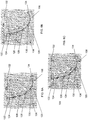
- FIGs. 9 and 11 show the prior art valve stent with uniform thickness leaflets. Optimized variable thickness leaflets according to the invention are shown in FIG 10 .
- FIGs. 9 and 10 are shown the results of simulations which were conducted with identical material models and mesh densities in order to ascertain the effects of the changes in leaflet geometry.
- FIG 10 shows reduced stress concentrations and magnitudes.
- FIG 11 the material model was changed to reflect the prior art composite leaflet design, while in FIG 10 the material model reflected the new xSIBS.
- the comparison of FIGs. 10 and 11 shows the combined effects of material and geometry changes. The result is that the modified leaflet geometry made from xSIBS produced lower stresses.
- FIGs. 9 and 10 are shown the results of simulations which were conducted with identical material models and mesh densities in order to ascertain the effects of the changes in leaflet geometry.
- FIG 10 shows reduced stress concentrations and magnitudes.
- FIG 11 the material model was changed to reflect the prior art composite leaflet design, while in FIG 10 the material model reflected the
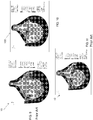
- FIGs. 16, 17 show the effects of a flexible stent on the stress distribution in the leaflets using the prior art stent geometry with both uniform thickness composite leaflets in FIG. 16 with a prior art composite material, compared to customized thickness leaflets with corresponding material models of the present invention of FIG. 17 , with xSIBS material.
- a flexible stent made of xSIBS produced low stresses.
- Valves shown in FIGs. 18 and 19 depict a comparison of stent design changes.
- the stent shown in FIG. 18 incorporates some of the features of the present disclosure, and new stent geometries are shown in stent of FIG. 19 .
- Both the valves shown in FIGS. 18 and 19 have customized thickness leaflets and the xSIBS material model.
- the new stent design (geometries) shown in FIG. 19 produced lower stresses in the leaflets.
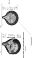
- FIGs. 20 and 21 show a comparison of stent design changes wherein the stent shown in FIG. 20 .
- Both the stents shown in FIGS. 20 and 21 include customized thickness leaflet and the xSIBS material according to the present invention.
- the leaflets of the valves are in semi-open valve positions.
- the stent design according to the present invention produced lower stresses in the leaflets. All numerical results in FIGS. 9-21 are shown with identical stress scales.
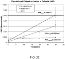
- Platelet thrombin generation rates were measured using a platelet activation state (PAS) assay. Results were compared measurements conducted with 21 mm Carpentier-Edwards Perimount Magna tissue valves mounted in the pulsatile LVAD and to a negative control, in which the LVAD was run without valves.
- PAS platelet activation state
- Platelet activation of the valves was measured using 120 ml of blood.
- a Berlin pulsatile left ventricular assist device (LVAD) was used to recirculate 250 ml of solution containing freshly isolated human platelets at a concentration of 20,000/ ⁇ l in platelet buffer.
- the system held two identical valves mounted inside custom designed valve holders oriented in opposite directions. The inflow and outflow ports were connected with a compliance reservoir.
- the pump rate was set to 90 BPM with a stroke volume of 65 ml, corresponding to a cardiac output (CO) of 5.85 1/min.
- the systole/diastole ratio was set to 0.375.
- the recirculation test was run for 30 min with samples taken in duplicate every 10 min.
- PAR platelet activation rates
Landscapes
- Health & Medical Sciences (AREA)
- Engineering & Computer Science (AREA)
- Biomedical Technology (AREA)
- Cardiology (AREA)
- Oral & Maxillofacial Surgery (AREA)
- Transplantation (AREA)
- Heart & Thoracic Surgery (AREA)
- Vascular Medicine (AREA)
- Life Sciences & Earth Sciences (AREA)
- Animal Behavior & Ethology (AREA)
- General Health & Medical Sciences (AREA)
- Public Health (AREA)
- Veterinary Medicine (AREA)
- Manufacturing & Machinery (AREA)
- Prostheses (AREA)
Claims (15)
- Eine polymere Herzklappe, die Folgendes umfasst:einen Stent (110) mit einer Basis und einer Vielzahl sich von der Basis (112) auswärts erstreckender Pfeiler (114), die im Wesentlichen äquidistant zueinander sind; undeine Vielzahl von Klappensegeln (104, 106, 108), die jeweils an einem Ende mit einem entsprechenden Pfeiler verbunden sind, wobei jedes der Klappensegel mit der Basis verbunden ist, wobei jedes der Klappensegel entlang der Mittellinie im Zentrum derselben, gegenüber dem mit dem Pfeiler verbundenen Ende, ein operatives Ende (120) hat, wobei die operativen Enden der Klappensegel in eine geschlossene Position vorgespannt sind, so dass sie aneinander anstoßen, wobei die operativen Enden ausgebildet sind, um sich im Verhältnis zueinander rhythmisch zu öffnen und zu schließen,wobei das operative Ende (120) jedes der Klappensegel im Querschnitt eine Kante mit einer Querschnittsfläche einschließt, die mehrere Dicken entlang der Kante für die dazugehörigen Abschnitte des Klappensegels hat,wobei das operative Ende (120) jedes der Klappensegel einen obersten Abschnitt (122), einen untersten Abschnitt (134) undvier Abschnitte (124, 126, 128, 130) zwischen dem obersten (122) und dem untersten Abschnitt (134) umfasst, die mehrere Querschnittsdicken an verschiedenen Abschnitten der Klappensegel einschließen,wobei die Klappensegel (104, 106, 108) eine kundenspezifisch angepasste variable Dicke zur Minderung der Konzentration hoher Belastungen haben, so dass die Bereiche erwarteter hoher Belastung verdickt sind und die Bereiche erwarteter niedrigerer Belastung ausgedünnt sind.
- Die Klappe gemäß Anspruch 1, die drei der Pfeiler umfasst.
- Die Klappe gemäß Anspruch 1, wobei die Pfeiler (114) jeweils ungefähr 8 mm bis 10,5 mm vom operativen Ende jedes der Klappensegel (104, 106, 108) entfernt positioniert sind.
- Die Klappe gemäß Anspruch 1, wobei die Pfeiler (114) sich in einem Winkel von einer durch die Basis bestimmten horizontalen Ebene erstrecken, der größer ist als 90°, und die Pfeiler sich in einem stumpfen Winkel mit Bezug auf die Basis des Stents (110) erstrecken.
- Die Klappe gemäß Anspruch 1, wobei die Klappe (100) eine Herzklappe mit drei Klappensegeln ist.
- Die Klappe gemäß Anspruch 1, wobei die Klappe (100) xSIBS-Material umfasst.
- Die Klappe gemäß Anspruch 1, wobei die Pfeiler (114) im Wesentlichen gerundete Kanten eines im Allgemeinen rechteckigen oberen Abschnitts haben.
- Die Klappe gemäß Anspruch 1, wobei die Basis des Stents (110) einen halbkugelförmigen Grat (113) einschließt, der sich um einen Umfang der Basis (112) herum erstreckt.
- Die Klappe gemäß Anspruch 1, wobei die mehreren Dicken der Klappensegel (104, 106, 108) Dicken im Bereich von ungefähr 0,25 mm bis ungefähr 0,18 mm einschließen.
- Die Klappe gemäß Anspruch 1, wobei die mehreren Dicken entlang einer Kante des operativen Endes (20) der Klappensegel (104, 106, 108) Dicken im Bereich von ungefähr 0,25 mm bis ungefähr 0,18 mm einschließen.
- Die Klappe gemäß Anspruch 1, wobei die obersten (122) und untersten Abschnitte (134) des operativen Endes (120) der Klappensegel (104, 106, 108) eine Dicke von ungefähr 0,25 mm haben.
- Die Klappe gemäß Anspruch 1, wobei ein mittlerer Abschnitt (128) des operativen Endes der Klappensegel (104, 106, 108) eine Dicke von ungefähr 0,25 mm hat.
- Die Klappe gemäß Anspruch 1, wobei die obersten (122) und untersten (134) Abschnitte des operativen Endes (120) der Klappensegel (104, 106, 108) eine Dicke von ungefähr 0,25 mm haben, ein mittlerer Abschnitt (128) des operativen Endes der Klappensegel eine Dicke von ungefähr 0,25 mm hat und inkrementale Abstandsabschnitte (124, 126, 130) zwischen den obersten und untersten Abschnitten und dem mittleren Abschnitt (128) Dicken von ungefähr 0,18 mm und 0,20 mm haben.
- Die Klappe gemäß Anspruch 1, wobei der Stent einen Metallverstärkungsrahmen (200) einschließt, der in den Stent (110) eingebettet ist.
- Ein Verfahren zur Herstellung einer polymeren Herzklappe (100) durch Spritzgießen in einer Form, wobei das Verfahren das Konstruieren einer kundenspezifischen Form durch Folgendes umfasst:das Konfigurieren eines Stents mit einer Basis und einer Vielzahl sich von der Basis auswärts erstreckender Pfeiler (114) ;das Konfigurieren einer Vielzahl von Klappensegeln (104, 106, 108), die jeweils an einem Ende mit einem entsprechenden Pfeiler verbunden sind, wobei jedes der Klappensegel mit der Basis verbunden ist;das Formen jedes der Klappensegel, die ein operatives Ende gegenüber dem Ende (120) entlang einer Mittellinie im Zentrum der Klappensegel haben, gegenüber dem mit dem Pfeiler verbundenen Ende, wobei die operativen Enden der Klappensegel in eine geschlossene Position vorgespannt sind, so dass sie aneinander anstoßen, wobei das operative Ende (120) jedes der Klappensegel im Querschnitt eine Kante mit einer Querschnittsfläche einschließt, die mehrere Dicken entlang der Kante für die dazugehörigen Abschnitte des Klappensegels hat, wobei das operative Ende (120) jedes der Klappensegel einen obersten Abschnitt (122), einen untersten Abschnitt (134) und vier Abschnitte (124, 126, 128, 130) zwischen dem obersten (122) und dem untersten Abschnitt (134) umfasst, die mehrere Dicken von Querschnittsdicken an verschiedenen Abschnitten der Klappensegel einschließen, wobei die Klappensegel (104, 106, 108) eine kundenspezifisch angepasste variable Dicke zur Minderung der Konzentration hoher Belastungen haben, so dass die Bereiche erwarteter hoher Belastung verdickt sind und die Bereiche erwarteter niedrigerer Belastung ausgedünnt sind;das Konfigurieren der operativen Enden, um ausgebildet zu sein, um sich im Verhältnis zueinander rhythmisch zu öffnen und zu schließen; unddas Erwärmen einer Form, die aus den oben genannten Schritten resultiert.
Applications Claiming Priority (2)
| Application Number | Priority Date | Filing Date | Title |
|---|---|---|---|
| US201161546832P | 2011-10-13 | 2011-10-13 | |
| PCT/US2012/059845 WO2013055977A1 (en) | 2011-10-13 | 2012-10-12 | Polymeric heart valve |
Publications (3)
| Publication Number | Publication Date |
|---|---|
| EP2765954A1 EP2765954A1 (de) | 2014-08-20 |
| EP2765954A4 EP2765954A4 (de) | 2015-04-01 |
| EP2765954B1 true EP2765954B1 (de) | 2021-12-22 |
Family
ID=48082461
Family Applications (1)
| Application Number | Title | Priority Date | Filing Date |
|---|---|---|---|
| EP12840473.8A Active EP2765954B1 (de) | 2011-10-13 | 2012-10-12 | Polymere herzklappe |
Country Status (3)
| Country | Link |
|---|---|
| US (2) | US9655720B2 (de) |
| EP (1) | EP2765954B1 (de) |
| WO (1) | WO2013055977A1 (de) |
Cited By (15)
| Publication number | Priority date | Publication date | Assignee | Title |
|---|---|---|---|---|
| US11311376B2 (en) | 2019-06-20 | 2022-04-26 | Neovase Tiara Inc. | Low profile prosthetic mitral valve |
| US11357622B2 (en) | 2016-01-29 | 2022-06-14 | Neovase Tiara Inc. | Prosthetic valve for avoiding obstruction of outflow |
| US11389294B2 (en) | 2012-05-30 | 2022-07-19 | Neovasc Tiara Inc. | Methods and apparatus for loading a prosthesis onto a delivery system |
| US11389291B2 (en) | 2013-04-04 | 2022-07-19 | Neovase Tiara Inc. | Methods and apparatus for delivering a prosthetic valve to a beating heart |
| US11413139B2 (en) | 2011-11-23 | 2022-08-16 | Neovasc Tiara Inc. | Sequentially deployed transcatheter mitral valve prosthesis |
| US11419720B2 (en) | 2010-05-05 | 2022-08-23 | Neovasc Tiara Inc. | Transcatheter mitral valve prosthesis |
| US11464631B2 (en) | 2016-11-21 | 2022-10-11 | Neovasc Tiara Inc. | Methods and systems for rapid retraction of a transcatheter heart valve delivery system |
| US11491006B2 (en) | 2019-04-10 | 2022-11-08 | Neovasc Tiara Inc. | Prosthetic valve with natural blood flow |
| US11497602B2 (en) | 2012-02-14 | 2022-11-15 | Neovasc Tiara Inc. | Methods and apparatus for engaging a valve prosthesis with tissue |
| US11602429B2 (en) | 2019-04-01 | 2023-03-14 | Neovasc Tiara Inc. | Controllably deployable prosthetic valve |
| US11737872B2 (en) | 2018-11-08 | 2023-08-29 | Neovasc Tiara Inc. | Ventricular deployment of a transcatheter mitral valve prosthesis |
| US11779742B2 (en) | 2019-05-20 | 2023-10-10 | Neovasc Tiara Inc. | Introducer with hemostasis mechanism |
| US11793640B2 (en) | 2017-08-25 | 2023-10-24 | Neovasc Tiara Inc. | Sequentially deployed transcatheter mitral valve prosthesis |
| US11998447B2 (en) | 2019-03-08 | 2024-06-04 | Neovasc Tiara Inc. | Retrievable prosthesis delivery system |
| US12109111B2 (en) | 2015-12-15 | 2024-10-08 | Neovasc Tiara Inc. | Transseptal delivery system |
Families Citing this family (46)
| Publication number | Priority date | Publication date | Assignee | Title |
|---|---|---|---|---|
| JP5638003B2 (ja) | 2009-01-12 | 2014-12-10 | ユニバーシティ オブ マサチューセッツ ローウェル | ポリイソブチレン系ポリウレタン |
| WO2013055977A1 (en) | 2011-10-13 | 2013-04-18 | The Research Foundation Of State University Of New York | Polymeric heart valve |
| US9926399B2 (en) | 2012-11-21 | 2018-03-27 | University Of Massachusetts | High strength polyisobutylene polyurethanes |
| GB201403454D0 (en) * | 2014-02-27 | 2014-04-16 | Cambridge Entpr Ltd | Heart valve |
| US10507101B2 (en) | 2014-10-13 | 2019-12-17 | W. L. Gore & Associates, Inc. | Valved conduit |
| WO2017158148A1 (en) | 2016-03-17 | 2017-09-21 | Centro Cardiologico Monzino | Polymers and uses thereof in manufacturing of 'living' heart valves |
| WO2018165273A1 (en) | 2017-03-07 | 2018-09-13 | Cardiac Pacemakers, Inc. | Hydroboration/oxidation of allyl-terminated polyisobutylene |
| US11523940B2 (en) | 2017-03-17 | 2022-12-13 | W. L. Gore & Associates, Inc. | Delivery aids for glaucoma shunts |
| US10835638B2 (en) | 2017-08-17 | 2020-11-17 | Cardiac Pacemakers, Inc. | Photocrosslinked polymers for enhanced durability |
| CA3078607C (en) | 2017-10-31 | 2022-07-26 | W.L. Gore & Associates, Inc. | Valved conduit |
| US11472911B2 (en) | 2018-01-17 | 2022-10-18 | Cardiac Pacemakers, Inc. | End-capped polyisobutylene polyurethane |
| WO2019195860A2 (en) | 2018-04-04 | 2019-10-10 | Vdyne, Llc | Devices and methods for anchoring transcatheter heart valve |
| PL238746B1 (pl) | 2018-07-24 | 2021-09-27 | American Heart Of Poland Spolka Akcyjna | Sposób formowania prefabrykatów wykorzystywanych w produkcji systemów przezcewnikowej implantacji zastawki aortalnej oraz prefabrykat zastawki aortalnej |
| US12239573B2 (en) | 2018-08-29 | 2025-03-04 | W. L. Gore & Associates, Inc. | Drug therapy delivery systems and methods |
| US11071627B2 (en) | 2018-10-18 | 2021-07-27 | Vdyne, Inc. | Orthogonally delivered transcatheter heart valve frame for valve in valve prosthesis |
| US12186187B2 (en) | 2018-09-20 | 2025-01-07 | Vdyne, Inc. | Transcatheter deliverable prosthetic heart valves and methods of delivery |
| US10595994B1 (en) | 2018-09-20 | 2020-03-24 | Vdyne, Llc | Side-delivered transcatheter heart valve replacement |
| US10321995B1 (en) | 2018-09-20 | 2019-06-18 | Vdyne, Llc | Orthogonally delivered transcatheter heart valve replacement |
| US11278437B2 (en) | 2018-12-08 | 2022-03-22 | Vdyne, Inc. | Compression capable annular frames for side delivery of transcatheter heart valve replacement |
| US11344413B2 (en) | 2018-09-20 | 2022-05-31 | Vdyne, Inc. | Transcatheter deliverable prosthetic heart valves and methods of delivery |
| US11109969B2 (en) | 2018-10-22 | 2021-09-07 | Vdyne, Inc. | Guidewire delivery of transcatheter heart valve |
| USD977642S1 (en) | 2018-10-29 | 2023-02-07 | W. L. Gore & Associates, Inc. | Pulmonary valve conduit |
| US11678983B2 (en) | 2018-12-12 | 2023-06-20 | W. L. Gore & Associates, Inc. | Implantable component with socket |
| US11253359B2 (en) | 2018-12-20 | 2022-02-22 | Vdyne, Inc. | Proximal tab for side-delivered transcatheter heart valves and methods of delivery |
| US10653522B1 (en) | 2018-12-20 | 2020-05-19 | Vdyne, Inc. | Proximal tab for side-delivered transcatheter heart valve prosthesis |
| WO2020146842A1 (en) | 2019-01-10 | 2020-07-16 | Vdyne, Llc | Anchor hook for side-delivery transcatheter heart valve prosthesis |
| US11273032B2 (en) | 2019-01-26 | 2022-03-15 | Vdyne, Inc. | Collapsible inner flow control component for side-deliverable transcatheter heart valve prosthesis |
| US11185409B2 (en) | 2019-01-26 | 2021-11-30 | Vdyne, Inc. | Collapsible inner flow control component for side-delivered transcatheter heart valve prosthesis |
| GB201902717D0 (en) | 2019-02-28 | 2019-04-17 | Univ Bristol | Heart valve |
| EP4729034A2 (de) | 2019-03-05 | 2026-04-22 | VDyne, Inc. | Trikuspidalregurgitationssteuerungsvorrichtungen für orthogonale transkatheterherzklappenprothese |
| US11173027B2 (en) | 2019-03-14 | 2021-11-16 | Vdyne, Inc. | Side-deliverable transcatheter prosthetic valves and methods for delivering and anchoring the same |
| US11076956B2 (en) | 2019-03-14 | 2021-08-03 | Vdyne, Inc. | Proximal, distal, and anterior anchoring tabs for side-delivered transcatheter mitral valve prosthesis |
| US10631983B1 (en) | 2019-03-14 | 2020-04-28 | Vdyne, Inc. | Distal subannular anchoring tab for side-delivered transcatheter valve prosthesis |
| US10758346B1 (en) | 2019-03-14 | 2020-09-01 | Vdyne, Inc. | A2 clip for side-delivered transcatheter mitral valve prosthesis |
| AU2020267390B2 (en) | 2019-05-04 | 2025-12-04 | Vdyne, Inc. | Cinch device and method for deployment of a side-delivered prosthetic heart valve in a native annulus |
| WO2021035032A1 (en) | 2019-08-20 | 2021-02-25 | Vdyne, Inc. | Delivery and retrieval devices and methods for side-deliverable transcatheter prosthetic valves |
| EP4684767A3 (de) | 2019-08-26 | 2026-04-08 | VDyne, Inc. | Seitlich freisetzbare transkatheter-prothesenventile |
| WO2021090348A1 (en) * | 2019-11-07 | 2021-05-14 | Madanat Sahar | A material dispensing device |
| US11234813B2 (en) | 2020-01-17 | 2022-02-01 | Vdyne, Inc. | Ventricular stability elements for side-deliverable prosthetic heart valves and methods of delivery |
| US12527691B2 (en) | 2021-11-05 | 2026-01-20 | W. L. Gore & Associates, Inc. | Fluid drainage devices, systems, and methods |
| US20240108462A1 (en) * | 2022-10-04 | 2024-04-04 | Medtronic Vascular, Inc. | Valve prosthesis having robust prosthetic valve and method |
| EP4601585A1 (de) | 2022-10-14 | 2025-08-20 | Vdyne, Inc. | Vorrichtungen und verfahren zur freisetzung einer herzklappenprothese mit supraannularer stütze |
| CN116509602B (zh) * | 2023-05-31 | 2024-02-06 | 苏州心岭迈德医疗科技有限公司 | 高分子心脏瓣膜及其制备方法 |
| CN116849873A (zh) * | 2023-07-17 | 2023-10-10 | 苏州心岭迈德医疗科技有限公司 | 人工高分子心脏瓣膜 |
| CN116687625B (zh) * | 2023-08-08 | 2023-11-03 | 上海心纪元医疗科技有限公司 | 一种高分子瓣用支架及其制作方法 |
| GB202400525D0 (en) | 2024-01-15 | 2024-02-28 | Cambridge Entpr Ltd | Apparatus |
Family Cites Families (21)
| Publication number | Priority date | Publication date | Assignee | Title |
|---|---|---|---|---|
| US4222126A (en) * | 1978-12-14 | 1980-09-16 | The United States Of America As Represented By The Secretary Of The Department Of Health, Education & Welfare | Unitized three leaflet heart valve |
| SU1144216A1 (ru) * | 1982-06-30 | 1987-10-07 | Институт Механики Полимеров Ан Латвсср | Протез клапана сердца |
| GB9206449D0 (en) | 1992-03-25 | 1992-05-06 | Univ Leeds | Artificial heart valve |
| GB9312666D0 (en) * | 1993-06-18 | 1993-08-04 | Vesely Ivan | Bioprostetic heart valve |
| GB9701479D0 (en) | 1997-01-24 | 1997-03-12 | Aortech Europ Ltd | Heart valve |
| US6666885B2 (en) * | 1999-04-16 | 2003-12-23 | Carbomedics Inc. | Heart valve leaflet |
| US6174331B1 (en) | 1999-07-19 | 2001-01-16 | Sulzer Carbomedics Inc. | Heart valve leaflet with reinforced free margin |
| US20030097175A1 (en) * | 1999-12-08 | 2003-05-22 | O'connor Bernard | Heart valve prosthesis and method of manufacture |
| GB0114345D0 (en) * | 2001-06-13 | 2001-08-08 | Aortech Europ Ltd | Heart valve prosthesis and method of manufacture |
| JP2004510471A (ja) * | 2000-09-21 | 2004-04-08 | セント・ジュード・メディカル・インコーポレーテッド | 強化されたポリマーリーフレットを有する弁プロテーゼ |
| US6953332B1 (en) * | 2000-11-28 | 2005-10-11 | St. Jude Medical, Inc. | Mandrel for use in forming valved prostheses having polymer leaflets by dip coating |
| US6726715B2 (en) * | 2001-10-23 | 2004-04-27 | Childrens Medical Center Corporation | Fiber-reinforced heart valve prosthesis |
| US20030114924A1 (en) | 2001-12-18 | 2003-06-19 | Riyad Moe | Polymer heart valve |
| ATE401843T1 (de) * | 2003-03-20 | 2008-08-15 | Aortech Internat Plc | Ventil |
| US20070118210A1 (en) | 2005-11-18 | 2007-05-24 | Leonard Pinchuk | Trileaflet Heart Valve |
| US8834912B2 (en) * | 2005-12-30 | 2014-09-16 | Boston Scientific Scimed, Inc. | Medical devices having multiple charged layers |
| EP2247264A4 (de) | 2008-02-29 | 2011-08-31 | Florida Int Univ Board Trustees | Mithilfe eines katheters einsetzbare künstliche herzklappenprothese mit mehreren klappensegeln sowie intravaskuläres einsatzsystem für eine mithilfe eines katheters einsetzbare künstliche herzklappenprothese |
| US10512537B2 (en) * | 2010-04-16 | 2019-12-24 | Abiomed, Inc. | Flow optimized polymeric heart valve |
| US8641757B2 (en) * | 2010-09-10 | 2014-02-04 | Edwards Lifesciences Corporation | Systems for rapidly deploying surgical heart valves |
| WO2013055977A1 (en) | 2011-10-13 | 2013-04-18 | The Research Foundation Of State University Of New York | Polymeric heart valve |
| WO2013112298A1 (en) | 2012-01-27 | 2013-08-01 | Wake Forest University | Electroluminescent devices and applications thereof |
-
2012
- 2012-10-12 WO PCT/US2012/059845 patent/WO2013055977A1/en not_active Ceased
- 2012-10-12 US US14/351,455 patent/US9655720B2/en active Active
- 2012-10-12 EP EP12840473.8A patent/EP2765954B1/de active Active
-
2017
- 2017-04-20 US US15/492,227 patent/US10772722B2/en active Active
Cited By (23)
| Publication number | Priority date | Publication date | Assignee | Title |
|---|---|---|---|---|
| US12611303B2 (en) | 2010-05-05 | 2026-04-28 | Neovasc Tiara Inc. | Transcatheter mitral valve prosthesis |
| US11419720B2 (en) | 2010-05-05 | 2022-08-23 | Neovasc Tiara Inc. | Transcatheter mitral valve prosthesis |
| US12053369B2 (en) | 2011-11-23 | 2024-08-06 | Neovasc Tiara Inc. | Sequentially deployed transcatheter mitral valve prosthesis |
| US11413139B2 (en) | 2011-11-23 | 2022-08-16 | Neovasc Tiara Inc. | Sequentially deployed transcatheter mitral valve prosthesis |
| US11497602B2 (en) | 2012-02-14 | 2022-11-15 | Neovasc Tiara Inc. | Methods and apparatus for engaging a valve prosthesis with tissue |
| US12138159B2 (en) | 2012-02-14 | 2024-11-12 | Neovasc Tiara Inc. | Methods and apparatus for engaging a valve prosthesis with tissue |
| US11617650B2 (en) | 2012-05-30 | 2023-04-04 | Neovasc Tiara Inc. | Methods and apparatus for loading a prosthesis onto a delivery system |
| US11389294B2 (en) | 2012-05-30 | 2022-07-19 | Neovasc Tiara Inc. | Methods and apparatus for loading a prosthesis onto a delivery system |
| US11389291B2 (en) | 2013-04-04 | 2022-07-19 | Neovase Tiara Inc. | Methods and apparatus for delivering a prosthetic valve to a beating heart |
| US12109111B2 (en) | 2015-12-15 | 2024-10-08 | Neovasc Tiara Inc. | Transseptal delivery system |
| US11357622B2 (en) | 2016-01-29 | 2022-06-14 | Neovase Tiara Inc. | Prosthetic valve for avoiding obstruction of outflow |
| US12193932B2 (en) | 2016-01-29 | 2025-01-14 | Neovasc Tiara Inc. | Prosthetic valve for avoiding obstruction of outflow |
| US11464631B2 (en) | 2016-11-21 | 2022-10-11 | Neovasc Tiara Inc. | Methods and systems for rapid retraction of a transcatheter heart valve delivery system |
| US12201524B2 (en) | 2016-11-21 | 2025-01-21 | Neovasc Tiara Inc. | Methods and systems for rapid retraction of a transcatheter heart valve delivery system |
| US11793640B2 (en) | 2017-08-25 | 2023-10-24 | Neovasc Tiara Inc. | Sequentially deployed transcatheter mitral valve prosthesis |
| US11737872B2 (en) | 2018-11-08 | 2023-08-29 | Neovasc Tiara Inc. | Ventricular deployment of a transcatheter mitral valve prosthesis |
| US11998447B2 (en) | 2019-03-08 | 2024-06-04 | Neovasc Tiara Inc. | Retrievable prosthesis delivery system |
| US11602429B2 (en) | 2019-04-01 | 2023-03-14 | Neovasc Tiara Inc. | Controllably deployable prosthetic valve |
| US12036117B2 (en) | 2019-04-10 | 2024-07-16 | Neovasc Tiara Inc. | Prosthetic valve with natural blood flow |
| US11491006B2 (en) | 2019-04-10 | 2022-11-08 | Neovasc Tiara Inc. | Prosthetic valve with natural blood flow |
| US11779742B2 (en) | 2019-05-20 | 2023-10-10 | Neovasc Tiara Inc. | Introducer with hemostasis mechanism |
| US11931254B2 (en) | 2019-06-20 | 2024-03-19 | Neovasc Tiara Inc. | Low profile prosthetic mitral valve |
| US11311376B2 (en) | 2019-06-20 | 2022-04-26 | Neovase Tiara Inc. | Low profile prosthetic mitral valve |
Also Published As
| Publication number | Publication date |
|---|---|
| US20170245989A1 (en) | 2017-08-31 |
| US10772722B2 (en) | 2020-09-15 |
| EP2765954A4 (de) | 2015-04-01 |
| WO2013055977A1 (en) | 2013-04-18 |
| US9655720B2 (en) | 2017-05-23 |
| EP2765954A1 (de) | 2014-08-20 |
| US20140303724A1 (en) | 2014-10-09 |
Similar Documents
| Publication | Publication Date | Title |
|---|---|---|
| US10772722B2 (en) | Polymeric heart valve | |
| Labrosse et al. | Geometric modeling of functional trileaflet aortic valves: development and clinical applications | |
| Rahmani et al. | Manufacturing and hydrodynamic assessment of a novel aortic valve made of a new nanocomposite polymer | |
| US20090112309A1 (en) | Collapsible Heart Valve with Polymer Leaflets | |
| US7455689B2 (en) | Four-leaflet stented mitral heart valve | |
| US11464639B2 (en) | Methods for creating sinus-matched aortic valves | |
| JP4319906B2 (ja) | 心臓弁補綴具の製造方法 | |
| De Gaetano et al. | A newly developed tri-leaflet polymeric heart valve prosthesis | |
| WO2021211062A1 (en) | A method for manufacturing personalized naturally designed mitral prosthesis | |
| Feng et al. | An in vitro feasibility study of the influence of configurations and leaflet thickness on the hydrodynamics of deformed transcatheter aortic valve | |
| Black et al. | Mechanical and other problems of artificial valves | |
| Zhu et al. | Numerical and in-vitro experimental assessment of the performance of a novel designed expanded-polytetrafluoroethylene stentless bi-leaflet valve for aortic valve replacement | |
| US12202202B2 (en) | Method for manufacturing personalized naturally designed mitral prosthesis | |
| Fríes et al. | Structural study of a polymeric aortic valve prosthesis. Analysis for a hyperelastic material | |
| Wu et al. | A review of polymeric heart valves leaflet geometric configuration and structural optimization | |
| JP2023554551A (ja) | 心臓弁プロテーゼ用型の製造方法 | |
| CN113924064B (zh) | 一种天然设计的二尖瓣假体 | |
| Gallocher | Durability assessment of polymer trileaflet heart valves | |
| Beith et al. | Strain energy minimization technique to design a surgical heart valve using a novel polymer | |
| Huang | Micromechanical simulations of heart valve tissues | |
| Jeevan et al. | Structural Analysis to Evaluate the Design of a Synthetic Mitral Valve Prosthesis | |
| Walker et al. | Development and in vitro assessment of a new two-leaflet replacement heart valve designed using computer-generated bubble surfaces | |
| Zhu et al. | An axis-specific mitral annuloplasty ring eliminates mitral regurgitation allowing mitral annular motion in an ovine model | |
| Chew et al. | Non-linear finite element modelling of porcine bioprosthetic valves | |
| Rassoli | A study of chemically treated pericardia to manufacture the leaflets of percutaneous heart valves: biomechanical analyses and modelisation |
Legal Events
| Date | Code | Title | Description |
|---|---|---|---|
| PUAI | Public reference made under article 153(3) epc to a published international application that has entered the european phase |
Free format text: ORIGINAL CODE: 0009012 |
|
| 17P | Request for examination filed |
Effective date: 20140507 |
|
| AK | Designated contracting states |
Kind code of ref document: A1 Designated state(s): AL AT BE BG CH CY CZ DE DK EE ES FI FR GB GR HR HU IE IS IT LI LT LU LV MC MK MT NL NO PL PT RO RS SE SI SK SM TR |
|
| AX | Request for extension of the european patent |
Extension state: BA ME |
|
| A4 | Supplementary search report drawn up and despatched |
Effective date: 20150227 |
|
| RIC1 | Information provided on ipc code assigned before grant |
Ipc: A61F 2/24 20060101AFI20150223BHEP |
|
| STAA | Information on the status of an ep patent application or granted ep patent |
Free format text: STATUS: EXAMINATION IS IN PROGRESS |
|
| 17Q | First examination report despatched |
Effective date: 20180525 |
|
| GRAP | Despatch of communication of intention to grant a patent |
Free format text: ORIGINAL CODE: EPIDOSNIGR1 |
|
| STAA | Information on the status of an ep patent application or granted ep patent |
Free format text: STATUS: GRANT OF PATENT IS INTENDED |
|
| INTG | Intention to grant announced |
Effective date: 20210702 |
|
| GRAS | Grant fee paid |
Free format text: ORIGINAL CODE: EPIDOSNIGR3 |
|
| GRAA | (expected) grant |
Free format text: ORIGINAL CODE: 0009210 |
|
| STAA | Information on the status of an ep patent application or granted ep patent |
Free format text: STATUS: THE PATENT HAS BEEN GRANTED |
|
| RAP1 | Party data changed (applicant data changed or rights of an application transferred) |
Owner name: ARIZONA BOARD OF REGENTS ON BEHALF OF THE UNIVERSITY OF ARIZONA Owner name: THE RESEARCH FOUNDATION OF STATE UNIVERSITY OF NEW YORK |
|
| AK | Designated contracting states |
Kind code of ref document: B1 Designated state(s): AL AT BE BG CH CY CZ DE DK EE ES FI FR GB GR HR HU IE IS IT LI LT LU LV MC MK MT NL NO PL PT RO RS SE SI SK SM TR |
|
| REG | Reference to a national code |
Ref country code: GB Ref legal event code: FG4D |
|
| REG | Reference to a national code |
Ref country code: CH Ref legal event code: EP |
|
| REG | Reference to a national code |
Ref country code: DE Ref legal event code: R096 Ref document number: 602012077418 Country of ref document: DE |
|
| REG | Reference to a national code |
Ref country code: AT Ref legal event code: REF Ref document number: 1456592 Country of ref document: AT Kind code of ref document: T Effective date: 20220115 |
|
| REG | Reference to a national code |
Ref country code: IE Ref legal event code: FG4D |
|
| REG | Reference to a national code |
Ref country code: LT Ref legal event code: MG9D |
|
| PG25 | Lapsed in a contracting state [announced via postgrant information from national office to epo] |
Ref country code: RS Free format text: LAPSE BECAUSE OF FAILURE TO SUBMIT A TRANSLATION OF THE DESCRIPTION OR TO PAY THE FEE WITHIN THE PRESCRIBED TIME-LIMIT Effective date: 20211222 Ref country code: LT Free format text: LAPSE BECAUSE OF FAILURE TO SUBMIT A TRANSLATION OF THE DESCRIPTION OR TO PAY THE FEE WITHIN THE PRESCRIBED TIME-LIMIT Effective date: 20211222 Ref country code: FI Free format text: LAPSE BECAUSE OF FAILURE TO SUBMIT A TRANSLATION OF THE DESCRIPTION OR TO PAY THE FEE WITHIN THE PRESCRIBED TIME-LIMIT Effective date: 20211222 Ref country code: BG Free format text: LAPSE BECAUSE OF FAILURE TO SUBMIT A TRANSLATION OF THE DESCRIPTION OR TO PAY THE FEE WITHIN THE PRESCRIBED TIME-LIMIT Effective date: 20220322 |
|
| REG | Reference to a national code |
Ref country code: NL Ref legal event code: MP Effective date: 20211222 |
|
| REG | Reference to a national code |
Ref country code: AT Ref legal event code: MK05 Ref document number: 1456592 Country of ref document: AT Kind code of ref document: T Effective date: 20211222 |
|
| PG25 | Lapsed in a contracting state [announced via postgrant information from national office to epo] |
Ref country code: SE Free format text: LAPSE BECAUSE OF FAILURE TO SUBMIT A TRANSLATION OF THE DESCRIPTION OR TO PAY THE FEE WITHIN THE PRESCRIBED TIME-LIMIT Effective date: 20211222 Ref country code: NO Free format text: LAPSE BECAUSE OF FAILURE TO SUBMIT A TRANSLATION OF THE DESCRIPTION OR TO PAY THE FEE WITHIN THE PRESCRIBED TIME-LIMIT Effective date: 20220322 Ref country code: LV Free format text: LAPSE BECAUSE OF FAILURE TO SUBMIT A TRANSLATION OF THE DESCRIPTION OR TO PAY THE FEE WITHIN THE PRESCRIBED TIME-LIMIT Effective date: 20211222 Ref country code: HR Free format text: LAPSE BECAUSE OF FAILURE TO SUBMIT A TRANSLATION OF THE DESCRIPTION OR TO PAY THE FEE WITHIN THE PRESCRIBED TIME-LIMIT Effective date: 20211222 Ref country code: GR Free format text: LAPSE BECAUSE OF FAILURE TO SUBMIT A TRANSLATION OF THE DESCRIPTION OR TO PAY THE FEE WITHIN THE PRESCRIBED TIME-LIMIT Effective date: 20220323 |
|
| PG25 | Lapsed in a contracting state [announced via postgrant information from national office to epo] |
Ref country code: NL Free format text: LAPSE BECAUSE OF FAILURE TO SUBMIT A TRANSLATION OF THE DESCRIPTION OR TO PAY THE FEE WITHIN THE PRESCRIBED TIME-LIMIT Effective date: 20211222 |
|
| PG25 | Lapsed in a contracting state [announced via postgrant information from national office to epo] |
Ref country code: SM Free format text: LAPSE BECAUSE OF FAILURE TO SUBMIT A TRANSLATION OF THE DESCRIPTION OR TO PAY THE FEE WITHIN THE PRESCRIBED TIME-LIMIT Effective date: 20211222 Ref country code: SK Free format text: LAPSE BECAUSE OF FAILURE TO SUBMIT A TRANSLATION OF THE DESCRIPTION OR TO PAY THE FEE WITHIN THE PRESCRIBED TIME-LIMIT Effective date: 20211222 Ref country code: RO Free format text: LAPSE BECAUSE OF FAILURE TO SUBMIT A TRANSLATION OF THE DESCRIPTION OR TO PAY THE FEE WITHIN THE PRESCRIBED TIME-LIMIT Effective date: 20211222 Ref country code: PT Free format text: LAPSE BECAUSE OF FAILURE TO SUBMIT A TRANSLATION OF THE DESCRIPTION OR TO PAY THE FEE WITHIN THE PRESCRIBED TIME-LIMIT Effective date: 20220422 Ref country code: ES Free format text: LAPSE BECAUSE OF FAILURE TO SUBMIT A TRANSLATION OF THE DESCRIPTION OR TO PAY THE FEE WITHIN THE PRESCRIBED TIME-LIMIT Effective date: 20211222 Ref country code: EE Free format text: LAPSE BECAUSE OF FAILURE TO SUBMIT A TRANSLATION OF THE DESCRIPTION OR TO PAY THE FEE WITHIN THE PRESCRIBED TIME-LIMIT Effective date: 20211222 Ref country code: CZ Free format text: LAPSE BECAUSE OF FAILURE TO SUBMIT A TRANSLATION OF THE DESCRIPTION OR TO PAY THE FEE WITHIN THE PRESCRIBED TIME-LIMIT Effective date: 20211222 |
|
| PG25 | Lapsed in a contracting state [announced via postgrant information from national office to epo] |
Ref country code: PL Free format text: LAPSE BECAUSE OF FAILURE TO SUBMIT A TRANSLATION OF THE DESCRIPTION OR TO PAY THE FEE WITHIN THE PRESCRIBED TIME-LIMIT Effective date: 20211222 Ref country code: AT Free format text: LAPSE BECAUSE OF FAILURE TO SUBMIT A TRANSLATION OF THE DESCRIPTION OR TO PAY THE FEE WITHIN THE PRESCRIBED TIME-LIMIT Effective date: 20211222 |
|
| REG | Reference to a national code |
Ref country code: DE Ref legal event code: R097 Ref document number: 602012077418 Country of ref document: DE |
|
| PG25 | Lapsed in a contracting state [announced via postgrant information from national office to epo] |
Ref country code: IS Free format text: LAPSE BECAUSE OF FAILURE TO SUBMIT A TRANSLATION OF THE DESCRIPTION OR TO PAY THE FEE WITHIN THE PRESCRIBED TIME-LIMIT Effective date: 20220422 |
|
| PLBE | No opposition filed within time limit |
Free format text: ORIGINAL CODE: 0009261 |
|
| STAA | Information on the status of an ep patent application or granted ep patent |
Free format text: STATUS: NO OPPOSITION FILED WITHIN TIME LIMIT |
|
| PG25 | Lapsed in a contracting state [announced via postgrant information from national office to epo] |
Ref country code: DK Free format text: LAPSE BECAUSE OF FAILURE TO SUBMIT A TRANSLATION OF THE DESCRIPTION OR TO PAY THE FEE WITHIN THE PRESCRIBED TIME-LIMIT Effective date: 20211222 Ref country code: AL Free format text: LAPSE BECAUSE OF FAILURE TO SUBMIT A TRANSLATION OF THE DESCRIPTION OR TO PAY THE FEE WITHIN THE PRESCRIBED TIME-LIMIT Effective date: 20211222 |
|
| 26N | No opposition filed |
Effective date: 20220923 |
|
| PG25 | Lapsed in a contracting state [announced via postgrant information from national office to epo] |
Ref country code: SI Free format text: LAPSE BECAUSE OF FAILURE TO SUBMIT A TRANSLATION OF THE DESCRIPTION OR TO PAY THE FEE WITHIN THE PRESCRIBED TIME-LIMIT Effective date: 20211222 |
|
| PG25 | Lapsed in a contracting state [announced via postgrant information from national office to epo] |
Ref country code: MC Free format text: LAPSE BECAUSE OF FAILURE TO SUBMIT A TRANSLATION OF THE DESCRIPTION OR TO PAY THE FEE WITHIN THE PRESCRIBED TIME-LIMIT Effective date: 20211222 Ref country code: IT Free format text: LAPSE BECAUSE OF FAILURE TO SUBMIT A TRANSLATION OF THE DESCRIPTION OR TO PAY THE FEE WITHIN THE PRESCRIBED TIME-LIMIT Effective date: 20211222 |
|
| REG | Reference to a national code |
Ref country code: CH Ref legal event code: PL |
|
| REG | Reference to a national code |
Ref country code: BE Ref legal event code: MM Effective date: 20221031 |
|
| PG25 | Lapsed in a contracting state [announced via postgrant information from national office to epo] |
Ref country code: LU Free format text: LAPSE BECAUSE OF NON-PAYMENT OF DUE FEES Effective date: 20221012 |
|
| P01 | Opt-out of the competence of the unified patent court (upc) registered |
Effective date: 20230527 |
|
| PG25 | Lapsed in a contracting state [announced via postgrant information from national office to epo] |
Ref country code: LI Free format text: LAPSE BECAUSE OF NON-PAYMENT OF DUE FEES Effective date: 20221031 Ref country code: CH Free format text: LAPSE BECAUSE OF NON-PAYMENT OF DUE FEES Effective date: 20221031 |
|
| PG25 | Lapsed in a contracting state [announced via postgrant information from national office to epo] |
Ref country code: BE Free format text: LAPSE BECAUSE OF NON-PAYMENT OF DUE FEES Effective date: 20221031 |
|
| PG25 | Lapsed in a contracting state [announced via postgrant information from national office to epo] |
Ref country code: IE Free format text: LAPSE BECAUSE OF NON-PAYMENT OF DUE FEES Effective date: 20221012 |
|
| PG25 | Lapsed in a contracting state [announced via postgrant information from national office to epo] |
Ref country code: HU Free format text: LAPSE BECAUSE OF FAILURE TO SUBMIT A TRANSLATION OF THE DESCRIPTION OR TO PAY THE FEE WITHIN THE PRESCRIBED TIME-LIMIT; INVALID AB INITIO Effective date: 20121012 |
|
| PG25 | Lapsed in a contracting state [announced via postgrant information from national office to epo] |
Ref country code: CY Free format text: LAPSE BECAUSE OF FAILURE TO SUBMIT A TRANSLATION OF THE DESCRIPTION OR TO PAY THE FEE WITHIN THE PRESCRIBED TIME-LIMIT Effective date: 20211222 |
|
| PG25 | Lapsed in a contracting state [announced via postgrant information from national office to epo] |
Ref country code: MK Free format text: LAPSE BECAUSE OF FAILURE TO SUBMIT A TRANSLATION OF THE DESCRIPTION OR TO PAY THE FEE WITHIN THE PRESCRIBED TIME-LIMIT Effective date: 20211222 |
|
| PG25 | Lapsed in a contracting state [announced via postgrant information from national office to epo] |
Ref country code: TR Free format text: LAPSE BECAUSE OF FAILURE TO SUBMIT A TRANSLATION OF THE DESCRIPTION OR TO PAY THE FEE WITHIN THE PRESCRIBED TIME-LIMIT Effective date: 20211222 |
|
| PG25 | Lapsed in a contracting state [announced via postgrant information from national office to epo] |
Ref country code: MT Free format text: LAPSE BECAUSE OF FAILURE TO SUBMIT A TRANSLATION OF THE DESCRIPTION OR TO PAY THE FEE WITHIN THE PRESCRIBED TIME-LIMIT Effective date: 20211222 |
|
| PGFP | Annual fee paid to national office [announced via postgrant information from national office to epo] |
Ref country code: DE Payment date: 20251029 Year of fee payment: 14 |
|
| PGFP | Annual fee paid to national office [announced via postgrant information from national office to epo] |
Ref country code: GB Payment date: 20251027 Year of fee payment: 14 |
|
| PGFP | Annual fee paid to national office [announced via postgrant information from national office to epo] |
Ref country code: FR Payment date: 20251027 Year of fee payment: 14 |