EP2765960B1 - Aufblasbares und einstellbares magenband zur behandlung von adipositas - Google Patents
Aufblasbares und einstellbares magenband zur behandlung von adipositas Download PDFInfo
- Publication number
- EP2765960B1 EP2765960B1 EP12770171.2A EP12770171A EP2765960B1 EP 2765960 B1 EP2765960 B1 EP 2765960B1 EP 12770171 A EP12770171 A EP 12770171A EP 2765960 B1 EP2765960 B1 EP 2765960B1
- Authority
- EP
- European Patent Office
- Prior art keywords
- band
- hollow
- tube
- wall
- ring
- Prior art date
- Legal status (The legal status is an assumption and is not a legal conclusion. Google has not performed a legal analysis and makes no representation as to the accuracy of the status listed.)
- Active
Links
Images




Classifications
-
- A—HUMAN NECESSITIES
- A61—MEDICAL OR VETERINARY SCIENCE; HYGIENE
- A61F—FILTERS IMPLANTABLE INTO BLOOD VESSELS; PROSTHESES; DEVICES PROVIDING PATENCY TO, OR PREVENTING COLLAPSING OF, TUBULAR STRUCTURES OF THE BODY, e.g. STENTS; ORTHOPAEDIC, NURSING OR CONTRACEPTIVE DEVICES; FOMENTATION; TREATMENT OR PROTECTION OF EYES OR EARS; BANDAGES, DRESSINGS OR ABSORBENT PADS; FIRST-AID KITS
- A61F5/00—Orthopaedic methods or devices for non-surgical treatment of bones or joints; Nursing devices ; Anti-rape devices
- A61F5/0003—Apparatus for the treatment of obesity; Anti-eating devices
- A61F5/0013—Implantable devices or invasive measures
- A61F5/005—Gastric bands
-
- A—HUMAN NECESSITIES
- A61—MEDICAL OR VETERINARY SCIENCE; HYGIENE
- A61F—FILTERS IMPLANTABLE INTO BLOOD VESSELS; PROSTHESES; DEVICES PROVIDING PATENCY TO, OR PREVENTING COLLAPSING OF, TUBULAR STRUCTURES OF THE BODY, e.g. STENTS; ORTHOPAEDIC, NURSING OR CONTRACEPTIVE DEVICES; FOMENTATION; TREATMENT OR PROTECTION OF EYES OR EARS; BANDAGES, DRESSINGS OR ABSORBENT PADS; FIRST-AID KITS
- A61F5/00—Orthopaedic methods or devices for non-surgical treatment of bones or joints; Nursing devices ; Anti-rape devices
- A61F5/0003—Apparatus for the treatment of obesity; Anti-eating devices
- A61F5/0013—Implantable devices or invasive measures
- A61F5/003—Implantable devices or invasive measures inflatable
-
- A—HUMAN NECESSITIES
- A61—MEDICAL OR VETERINARY SCIENCE; HYGIENE
- A61F—FILTERS IMPLANTABLE INTO BLOOD VESSELS; PROSTHESES; DEVICES PROVIDING PATENCY TO, OR PREVENTING COLLAPSING OF, TUBULAR STRUCTURES OF THE BODY, e.g. STENTS; ORTHOPAEDIC, NURSING OR CONTRACEPTIVE DEVICES; FOMENTATION; TREATMENT OR PROTECTION OF EYES OR EARS; BANDAGES, DRESSINGS OR ABSORBENT PADS; FIRST-AID KITS
- A61F5/00—Orthopaedic methods or devices for non-surgical treatment of bones or joints; Nursing devices ; Anti-rape devices
- A61F5/0003—Apparatus for the treatment of obesity; Anti-eating devices
- A61F5/0013—Implantable devices or invasive measures
- A61F5/005—Gastric bands
- A61F5/0053—Gastric bands remotely adjustable
- A61F5/0056—Gastric bands remotely adjustable using injection ports
-
- A—HUMAN NECESSITIES
- A61—MEDICAL OR VETERINARY SCIENCE; HYGIENE
- A61F—FILTERS IMPLANTABLE INTO BLOOD VESSELS; PROSTHESES; DEVICES PROVIDING PATENCY TO, OR PREVENTING COLLAPSING OF, TUBULAR STRUCTURES OF THE BODY, e.g. STENTS; ORTHOPAEDIC, NURSING OR CONTRACEPTIVE DEVICES; FOMENTATION; TREATMENT OR PROTECTION OF EYES OR EARS; BANDAGES, DRESSINGS OR ABSORBENT PADS; FIRST-AID KITS
- A61F5/00—Orthopaedic methods or devices for non-surgical treatment of bones or joints; Nursing devices ; Anti-rape devices
- A61F5/0003—Apparatus for the treatment of obesity; Anti-eating devices
- A61F5/0013—Implantable devices or invasive measures
- A61F5/005—Gastric bands
- A61F5/0066—Closing devices for gastric bands
-
- B—PERFORMING OPERATIONS; TRANSPORTING
- B29—WORKING OF PLASTICS; WORKING OF SUBSTANCES IN A PLASTIC STATE IN GENERAL
- B29C—SHAPING OR JOINING OF PLASTICS; SHAPING OF MATERIAL IN A PLASTIC STATE, NOT OTHERWISE PROVIDED FOR; AFTER-TREATMENT OF THE SHAPED PRODUCTS, e.g. REPAIRING
- B29C45/00—Injection moulding, i.e. forcing the required volume of moulding material through a nozzle into a closed mould; Apparatus therefor
- B29C45/16—Making multilayered or multicoloured articles
Definitions
- the technical field of the invention is that of surgical implants intended to be placed around a segment of the digestive tract to narrow it, for example between the abdominal part of the esophagus and the stomach.
- the strangulation thus obtained creates, upstream of the stomach, a pocket of retention of the bolus of much smaller volume than the stomach, so that the signals inducing satiety are emitted early in the patient.
- Such implants are therefore used for the treatment of obesity.
- these implants may be of the type comprising an elongate and inflatable hollow body by means of a suitable fluid, for example physiological saline.
- a suitable fluid for example physiological saline.
- This hollow body is placed in the open position by the surgeon around a segment of the digestive tract located e.g. between the abdominal part of the esophagus and the stomach. The surgeon then connects the two ends of the implant to each other to lock the ring thus formed to a size corresponding to a basal level of constriction of the stomach.
- the surgeon can then adjust as much as necessary, the level of constriction, and thus weaning of the patient, by inflation / deflation of the implanted closed ring, from outside the patient's body by means of a syringe and an implantable septum chamber connected to the ring by a catheter, this adjustment being made during a simple hospitalization.
- French patent FR2887436-B1 discloses an inflatable gastric band comprising an elongated tubular body of flexible material, elastically deformable, the body defining an inflatable chamber and having a back and a working face.
- This belt also comprises connecting means arranged in relation to two ends of the tubular body and for closing the gastric belt in the form of a ring, the working face being disposed inside the ring.
- This belt finally comprises an inflation catheter for connection to inflating means and sealingly connected to the inflatable chamber via an inflation port in the back of the elongated tubular body.
- the inner face of the back of the tubular body has eight protuberances intended to provide support to the inner wall of the chamber in the vicinity of the inflation orifice formed in the back of the tubular body.
- the gastric belt according to the French patent FR2887436-B1 is perfectible with regard to all or some of the technical problems (a) to (i) mentioned above, in particular with regard to (a) the ease of placement of the implant around the stomach by the surgeon and more particularly, for introducing the catheter into the loops to form the ring around the stomach by looping.
- French patent FR2903297 discloses an inflatable gastric band-band according to the preamble of appended claim 1, more specifically a gastric band 1 comprising a tubular body 2 defining a sealed and inflatable chamber 3 having in elevation seen from above, a general C shape, as shown on the figure 1 attached which represents a section along the median longitudinal plane of the gastric belt according to the French patent FR2903297 , at rest and in the deflated state, the tubular body 2 has a generally flat shape and a rectangular cross section.
- the gastric band also comprises an inflation catheter 14 connecting an inflation orifice 16 arranged in the back 4 of the tubular body 2, inflation means.
- One end of the catheter 14 is intended to be passed through two arches 20,21 disposed on the back 4 of the tubular body 2 - on its curved free end portion - to form a ring by looping around the stomach.
- the end portion 18p of the catheter 16 comprises two non-return type locking means 22 in the form of a tree designed to cooperate with the hoops 20,21 to lock the ring in the closed position.
- the end portion 18p of the catheter 16 which comprises these non-return springs 22 is bent on an angular sector ⁇ of 45 to 75 ° of the same radius of curvature and in the extension of the arc formed by the tubular body on a tubular sector ⁇ between 160 and 230 ° C.
- This gastric belt according to the French patent FR2903297-B1 is also perfectible with regard to all the technical problems a to i mentioned above, especially with regard to the ease of installation around the stomach by the surgeon, especially for threading the proximal free end of the catheter in the passers-on provided on the distal end portion of the hollow body for forming a ring by looping.
- Requirement WO03 / 059215A1 discloses a preformed "C" shaped gastroplasty ring made of elastomeric material and connected to an inflation catheter. This relatively rigid O-ring is intended to be closed around the patient's stomach.
- the ring comprises an inflatable annular compression chamber and delimited by a "U" (external) dorsal reinforcement on which are molded so-called “lateral” walls (internal part) to form an assembly presented as “monobloc", but which does not is not really, because it consists of several overmolded pieces (discontinuity of materials).
- the backing is made of a material with a hardness greater than that of the inner part of the ring.
- the single-bolt closure means consist of a female means formed by a ring integral with the end of the ring and by a male means formed by a tip secured to the other end of the ring. This ring and this tip are not, at rest, in the extension of the ring preformed "C".
- This ring has the disadvantage of being not really monobloc, difficult to manufacture, and to have only one locking latch, which increases the risk of untimely opening and associated complications.
- This ring has, in addition, a significant thickness and a certain rigidity due to its manufacturing process by preforming. Its placement around the stomach is a delicate and risky operation because it requires the passage of the entire ring under (behind) the stomach with the risk of damage to the spleen and / or the portal vein. near the stomach.
- the rigid closure end of this ring is protruding in the locked position and further comprises rigid tongues, so that the risk of injury to the peripheral organs of the patient's stomach are real.
- the present invention aims to improve surgical implants of the type of those described in patents FR2887436-B1 , FR2903297-B1 and WO 03/059215 A1 , with regard to the technical problems mentioned above.
- the inflatable and adjustable gastric band-ring according to the invention aims as much as possible to ensure the comfort and safety of the patient, in particular by facilitating the surgeon's work for the rapid and reliable insertion of the ring around a patient. given segment of the digestive tract.
- the closed ring, thus put in place, must be stable as to its positioning, non-aggressive and effective.
- the ring band according to the invention must have a reinforcement of the dorsal outer wall so that the inflation is best performed centripetally.
- the deflation does not cause occlusion of the opening of the inflation port of the outer wall by the inner wall, due to a phenomenon of depression during deflation.
- the proximal end of the flexible tube is its free end closest to the outside of the body of the patient in which the implant is placed, that is to say the free end intended to be connected by means of inflation / deflation.
- the distal end of the flexible tube is the end opposite its proximal end, this distal end is connected to the proximal end of the hollow band of the band-ring according to the invention.
- the proximal end of this hollow band is therefore the end of the hollow band closest to the flexible tube.
- the distal end of the hollow band is its free end opposite its proximal end.
- hardness D1 denotes the Shore A hardness of the constituent material (s) of the band-ring and in particular of the hollow flexible band.
- the term flexible band designates a substantially thin device when in the rest position, that is to say not inflated.
- Monoblock means a product made in one piece, preferably obtained using a sequential multi-injection mold guaranteeing the melting of the molded materials constituting the product, preferably silicones, and the continuity of said materials. .
- a monobloc product is obtained without overmoulding, that is to say with a continuum of molded material.
- the fact that the hollow flexible band has a rectilinear part in its distal region has the advantage of facilitating the installation of the band-ring and particularly its closure. Threading the proximal end of the flexible tube through the passage or passers of the rectilinear portion of the outer wall of the hollow strip can be done in a single gesture, in one go when they are in the same axis. Indeed, if the distal portion of the hollow flexible band was curved, to close the band-ring, the surgeon performing the operation (under laparoscopy) should pass the end proximal of the tube in the first passing along an axis and then recover the proximal end of the tube to pass in the second passing along another axis.
- the fact that the rectilinear part in the distal portion of the flexible band hollow on its outer wall carries, in a preferred embodiment, at least two loops, also provides additional safety for the patient.
- the ring band closed with a single passer could open, which presents a risk for the patient and requires additional surgery.
- the band-ring closed with a single passer is twisted and may be upside down around the stomach, the outer wall is then in direct contact with the stomach. The flexible band-ring could then damage the stomach with passers-by or notches or cause erosion or migration into the stomach, which is dangerous.
- the length of the rectilinear portion of the distal portion of the flexible hollow band, at rest, that is to say not inflated is between 10 and 40%, more preferably between 17 and 35%, more preferably still between 21 and 33% of the total length of the hollow flexible band.
- the length of the rectilinear portion is 4.5 cm and the length of the flexible band is 18.5 cm.
- the length of the rectilinear portion therefore represents 24.3% of the length of the hollow flexible strip.
- the length of the band is measured from the distal end to the proximal end of the hollow flexible band.
- the distance between the two loops (taken between the proximal portion of the passer closest to the proximal end of the band and the distal portion of the passer closest to the distal end of the band) carried by the straight portion the distal portion of the hollow flexible band, at rest, that is to say not inflated, is between 10 and 40%, more preferably between 17 and 35%, more preferably between 21 and 33% of the length total of the hollow flexible band.
- the distance between the two loops is between 16 and 34mm ⁇ 1 mm and the length of the flexible band is between 108 and 122 mm ⁇ 1 mm. The distance between the two loops therefore represents between 12 and 32% of the length of the hollow flexible band
- the axis of this substantially rectilinear portion extending to the distal free end of the hollow flexible band is secant to the distal end region of the tube.
- the proximal end zone of the hollow strip is substantially rectilinear.
- the radius of curvature R of this circle is included in the following intervals given in mm and in increasing order of preference [10-21]; [13-20]; [14-19]; [15-18]; [17-18].
- the hollow flexible band of the band-ring has a length / width ratio of between 4.5 and 5.9.
- the width of the hollow flexible band of the band-ring is about 22 mm ⁇ 1 mm and the length of the hollow flexible band of the band-ring is between 108 mm and 122 mm ⁇ 1 mm, a ratio length / width between 4, 65 and 5.85.
- the hollow flexible band is monobloc and is made from at least two materials M1, M2, the material M1 constituting at least partly the outer wall and the material M2 at least partly constituting the outer wall.
- M1, M2 are chosen from silicone elastomers, differing at least in their respective hardnesses D1, D2 with D1> D2, and more particularly in increasing order of preference, D1> 1.1 (D2); D1> 1.2 (D2); 2 (D2)> D1> 1.3 (D2).
- the hollow flexible band as described above consisting of two materials M1 and M2 and having on its outer wall in its distal straight portion at least two loops is monobloc.
- the gastric band band once implanted be visible to the surgeon by means of usual medical imaging device such as X-rays.
- the ring-band according to the invention is in radio-opaque part.
- the longitudinal edges of the outer wall are protruding, and more preferably still at least partly radiopaque, especially X-rays.
- the distal end zone of the tube comprises at least two serrations arranged in series 10 1 & 10 2 and in the form of dovetails whose bases 1b and 10b are of different widths, the width 1 the notch 10 2 closest to the distal end being less than or equal to the width l 2 of the other notch 10 1 ( Figure 5 )
- the distal rectilinear part of the hollow flexible band makes it possible to guide the surgeon during the closure of the gastric band and thus facilitate this closure.
- the pass-through or loops being on the outer wall of the hollow flexible band, the closure of the ring is done when the notches of the tube are passed beyond their respective corresponding pass (s) .
- the tube covers the part (rectilinear at rest and curvilinear when the ring band is in place around the stomach) distal to the hollow flexible band. This has the additional advantage of limiting the risk of perforation or damage to peripheral organs to the stomach during the installation and closure of the ring.
- the inflation tube of the devices of the prior art is usually placed substantially perpendicular to the distal portion of the ring or at least non-tangential to the latter.
- the tube will thus go along the outer wall of the rectilinear part of the hollow flexible strip until it locks in the closed position, for example the dovetail notches having been passed. through the passers-by.
- the band-ring when the band-ring is closed, in the inflated position or not, the respective proximal and distal ends of the hollow flexible band come into contact with each other.
- the band-ring when the band-ring is placed around the stomach, it is in contact only with the inner wall of the hollow flexible band, without any protuberance. The device once form is thus atraumatic for the stomach and the surrounding organs.
- the inflation opening of the hollow flexible band is formed in its outer wall at the proximal end zone thereof.
- this outer wall advantageously has, on its inner face, recesses, preferably grooves, more preferably still parallel longitudinal grooves and / or parallel transverse grooves, at least a portion of these recesses being arranged on both sides. other of the inflation opening, said recesses being intended to prevent occlusion of the inflation opening by the inner wall of the hollow flexible strip opposite this opening, in particular during deflation.
- At least one of the longitudinal edges of the hollow flexible band is blunted or rounded.
- the width of the inner wall of the hollow flexible strip according to the invention in the inflated position or not, does not exceed the width of the outer wall of the hollow flexible strip, that is to say that it does not protrude on either side of it.
- the band-ring is obtained by molding using a mold whose characteristics define said band-ring.
- the ring-band according to the invention is obtained by sequential multi-injection within the same mold.
- the invention also relates to the mold itself and the process for obtaining the ring-band by molding using said mold, the molding being preferably monoblock by sequential multi-injection within the same mold.
- the invention relates to the use, in a ring-band of the type of the one according to the invention, of recesses preferably of grooves, more preferably of parallel longitudinal grooves of which at least a part is disposed on either side of the inflation opening; these recesses being formed in the inner face of the outer wall also comprising the inflation opening, to prevent occlusion of the inflation opening by the inner wall of the hollow flexible strip opposite this opening, in particular during deflation.
- the present invention constitutes a significant advance in the field of gastric implants for the treatment of obesity.
- the most important achievements are in the area of surgical assistance, which enhances the safety and comfort of industrial manufacturing by the economical and efficient production of a single-piece molded assembly comprising at least two or even at least three materials, eg using multi-injection molds.
- the gastric band-band according to the invention is designated by the general reference 1 in the appended figures.
- This ring band 1 inflatable and adjustable around a segment of the digestive tract to narrow it by constriction comprises a hollow flexible band 2 made of an elastic material, for example a silicone elastomer.
- This hollow strip 2 is elongated and has a substantially rectangular shape in right cross section.
- This hollow flexible band 2 comprises a substantially rectilinear proximal end portion 13 p and then a curved portion 14 extending through a substantially rectilinear distal end portion 9 d and carrying closure means 11.
- the proximal end portion 13 p of the hollow flexible band 2 is connected to a flexible inflating tube 5 and more precisely to the distal end portion 16 of straight end 6 of said flexible tube 5 equipped with closure means 10, complementary to the closure means 11 of the hollow flexible band 2 worn, preferably on the outer wall of the distal straight portion of the hollow strip.
- the inflatable flexible tube 5 has a proximal end 7 p free intended to be connected to inflating means 8 including themselves an inflation module 80 shown on the figure 8 and equipped with a septum and allowing the injection of liquid of inflating or aspirating inflation fluid using a syringe.
- This hollow strip 2 is in the general shape of a hook with a curved preformed portion 14, for example substantially circular, characterized by an angular sector S defined from the center of the circular portion between the proximal end 13 p and the distal end 9 d of the band 2 between 320 and 310 °.
- its angular sector S 1 which extends between the intersection of the axis VII-VII with the hollow strip 2 at the end of the zone 13 of proximal end 13 p and the beginning of the distal free end portion 9 d of this band 2 is between 180 and 270 °.
- the axis of the distal free end portion 9 d straight of the hollow flexible band 2 is secant to the distal end portion 6d rectilinear 6d flexible tube 5, so as to facilitate the winding of the hollow band 2 around the stomach by the surgeon.
- the inner face of the outer wall 18 has parallel longitudinal grooves 25 and two parallel transverse grooves 26 located at the ends of this inner face. Furthermore, an inflation opening 4 connecting the flexible tube 5 to the inside of the hollow flexible band 2, is formed in the outer wall 18 in the vicinity of the proximal end 13 p .
- the transverse groove 26 provided at this end is disposed on either side of the opening 4, as are the end portions close to the longitudinal grooves 25.
- the closure means 11 disposed on the outer wall 18 of the hollow flexible strip 2 are in this preferred embodiment of the loops 11 1 , 11 2 .
- These passers are preferably at least two in number. It may of course be other means adapted to ensure a good closure of the gastric band.
- passers-by in order to promote this passage of the flexible tube and reduce, as much as possible, the efforts required for this surgical procedure, passers-by have, on their internal face, a series of streaks that come reduce the contact surface of the flexible tube with the corresponding passer, so as to reduce frictional forces. These ridges extend parallel to the longitudinal axis of the hollow flexible band 2 and in the insertion direction of the flexible tube 5.
- the flexible band hollow and the passers-by that it carries are monobloc, that is to say that they form only one.
- the distance between the loops (taken between the proximal end of the proximal passer 11 1 closest to the proximal end of the band 13 p and the distal end of the distal pass 11 2 closest to the distal end 9 d of the band) carried by the straight portion of the distal portion of the hollow flexible band is about 38 mm. This represents about 21% of the total length of the inner wall of the hollow band taken between the proximal end 13 p and the distal end 9 d .
- the hollow flexible strip 2 also comprises two parallel radiopaque longitudinal strips 21, in the vicinity of the longitudinal edges 22 of the outer wall 18. As shown in FIG. figure 5 a radiopaque band 24 is also provided on the proximal transverse edge of the hollow flexible band 2.
- the hollow flexible strip 2 has the characteristic of having an outer wall 18 made of an elastomeric material, for example biocompatible silicone - M1 hardness D1, while the inner wall 17 is made of an elastomeric material -for example biocompatible silicone- M2 of hardness D2 less than D1.
- D1 is for example equal to 0.5 x D2.
- the outer wall 18 thus reinforced ensures better control of the stomach restriction during inflation of the hollow flexible band 2 placed in a stable manner around the stomach.
- the hollow flexible band 2 is produced by molding in one piece with the two constituent materials M1 and M2, M1 for the outer wall 18 comprising, in the distal rectilinear part of the hollow flexible band, at least two loops, and M2 for the internal wall 17 but there may also be a third material M3 corresponding to the parallel radiopaque longitudinal strips 21 and to the radiopaque transverse band 24.
- the distal end 6 d of the flexible tube 5 is connected to the flexible band 2 hollow through the opening 4 of inflation formed in the outer wall 18.
- the flexible tube 5 is equipped, in its portion 16 of distal end 6 d rectilinear closure means loop closure, by noose, which are complementary to those 11 1 , 11 2 of the straight portion 15 of the distal end 9 d of the hollow flexible band 2.
- the closing means 10 1 , 10 2 are dovetail-shaped notches whose bases 10 1b and 10 2b are of different widths l 1 , l 2 .
- the width I 1 of the notch 10 1 closest to the distal end 6 d being less than the width l 2 of the other notch 10 2.
- these widths l 1 , l 2 may be equal.
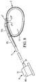
- the bases 10 1b and 10 2b of the dovetails 10 1 and 10 2 are in an anti-return abutment against the hoops 11 1 , 11 2 , so as to lock the hollow flexible band 2 in ring form in the closed position, as shown in FIG. figure 8 .
- the proximal free end 7 p of the flexible tube 5 can be advantageously closed by a stopper, of conical shape, which avoids the introduction of material into the catheter channel and facilitates the introduction of the catheter through the loops January 11 11 2 when closing the hollow flexible band 2 to form the ring. After formation of the ring, the surgeon removes the cap and connects the flexible tube to the inflation means 8.
- the inflation means 8 is a first inflation means 8:
- the inflation means 8 are constituted as shown in FIG. figure 8 an implantable catheter chamber 80 provided with a septum 81 through which a needle can be planted to puncture and inject inflation fluid.
- the implant according to the invention can be implemented by laparoscopic way.
- optical locating means are provided on the hollow flexible band 2 and / or on the flexible tube 5.
- the ring band 1 according to the mention comprises a radiopaque insert 40 housed in the hollow flexible strip 2, said insert 40 preferably comprising an extension 41 of at least one of the walls 17-18-19 90-130 of the flexible band 2 hollow, is more preferably still, an extension 41 of the distal end wall 42 of the hollow band 2.
- the ring band 1 is obtained from an intermediate molding 1 ', which is demolded by an opening 91 provided instead of the distal end wall 42 of the flexible strip 2 hollow said distal end wall 42 being fixed to the intermediate molding 1 'after demolding and the distal end wall 42 preferably forming one end of a radiopaque insert 40 housed in the hollow flexible strip 2.
- the radiopaque insert 40 consists of a base 42 having an extension 41, as shown in FIGS. Figures 11A-11B-12A-12B .
- the base 42 of the insert 40 may be, for example, made of silicone elastomer, while the extension 41 extending from this base 42 and forming the radiopaque portion itself is, for its part, made to from a silicone elastomer loaded with a radiopaque material, for example barium sulfate.
- the extension 41 is, for example, constituted by two parallel rods 43 integral with the base 42 at one of their ends and connected to one another at the free end 44 of the extension 41.
- a spacer 45 connects to one another the rods 43 of the extension 41.
- This radio-opaque insert 40 shown in FIGS. Figures 11A-11B can be introduced inside the hollow flexible band 2 of the ring band 1, by a release opening 91 provided on an intermediate molded part 1 ', precursor of the ring band 1 finished.
- the extension 42 is independent of the hollow strip 2, while the base 42 of the insert 40 forms a stopper closing the opening 91, for forming the distal end wall 90 of the hollow flexible band 2.
- Fixing the base 42 (or plug) to the hollow flexible band can be done by any suitable means for example gluing, welding ....
- the extension 43 advantageously has a length less than that of the chamber 30 of the flexible strip 2 hollow, so as not to obstruct the opening 4 of inflation.
- the extension 43 of the insert 40 is immersed in the fluid filling the chamber 30 of the flexible strip 2 hollow.
Landscapes
- Health & Medical Sciences (AREA)
- Engineering & Computer Science (AREA)
- Biomedical Technology (AREA)
- Heart & Thoracic Surgery (AREA)
- Child & Adolescent Psychology (AREA)
- Obesity (AREA)
- Nursing (AREA)
- Orthopedic Medicine & Surgery (AREA)
- Veterinary Medicine (AREA)
- Public Health (AREA)
- Vascular Medicine (AREA)
- Life Sciences & Earth Sciences (AREA)
- Animal Behavior & Ethology (AREA)
- General Health & Medical Sciences (AREA)
- Mechanical Engineering (AREA)
- Manufacturing & Machinery (AREA)
- Surgical Instruments (AREA)
- Prostheses (AREA)
Claims (12)
- Aufblasbares, anpassbares Magen-Ringband (1), welches dazu vorgesehen ist, um einen Abschnitt des Verdauungstraks herum platziert zu werden, um ihn verengen, wobei das Ringband umfasst:- ein flexibles, hohles, elastisches Band (2), umfassend eine innere Wand (17) und eine äußere Wand (18), welche eine dichte aufblasbare Kammer (30) definieren, welche eine Öffnung (4) zum Aufblasen aufweist;- eine flexible Aufblasröhre, deren distales Ende (6d) an der Öffnung (4) zum Aufblasen des Bands (2) angeschlossen ist, und deren proximales Ende (7p) dazu vorgesehen ist, mit Aufblasmitteln (8) verbunden zu werden;- wobei die Röhre (5) und das Band (2) in ihren jeweiligen Zonen (6) und (9) der distalen Enden mit komplementären Schließmitteln (10) und (11) ausgestattet sind, welche in der Lage sind, miteinander zusammenzuwirken, um das Festsetzen eines Rings (12) in geschlossener Position sicherzustellen, welcher durch eine Annäherung des distalen Endes (9d) und des proximalen Endes (13p) des Bands (2) nach dem Schlingenprinzip gebildet ist, insbesondere um den zu verengenden Abschnitt des Verdauungstrakts herum;dadurch gekennzeichnet, dass
wobei die Schließmittel (10) der Röhre (5) wenigstens einen Einschnitt aufweisen und die Schließmittel (11) des Bands (2) wenigstens eine Schlaufe aufweisen, vorzugsweise wenigstens zwei Schlaufen, derart, dass das proximale Ende (7p) der Röhre (5) dazu vorgesehen ist, durch die wenigstens eine Schlaufe (11) des Bands (2) bis zu einer festgesetzten Schließposition einzugreifen, sobald der wenigstens eine Einschnitt (10) über die wenigstens eine Schlaufe (11) hinaus geführt wird;- das flexible, hohle Band (2) in Ruhe, ohne Eingriff der Röhre (5) und des Bands (2) miteinander zum Bilden des Rings (12) einen vorgeformten Kurvenabschnitt (14) aufweist, welcher sich ausgehend von seiner Zone (13) des proximalen Endes erstreckt und in einem im Wesentlichen geradlinigen Abschnitt (15) bis zu dem freien distalen Ende (9d) des Bands (2) weiter verläuft, wobei der im Wesentlichen geradlinige Abschnitt (15) eine Länge aufweist, welche zwischen 10 und 40%, vorzugsweise zwischen 17 und 35%, weiter vorzugsweise zwischen 17 und 35%, weiter vorzugsweise zwischen 21 und 33% einer Gesamtlänge des flexiblen, hohlen Bands beträgt, um den Eingriff des proximalen Endes (7p) der Röhre (5) durch die wenigstens eine Schlaufe (11) des Bands (2) hindurch zu erleichtern, und- die wenigstens eine Schlaufe an der äußeren Wand (18) des im Wesentlichen geradlinigen Abschnitts (15) des flexiblen, hohlen Bands (2) angeordnet ist. - Ringband (1) nach Anspruch 1, dadurch gekennzeichnet, dass die Achse des im Wesentlichen geradlinigen Abschnitts (15) des Bands (2) die Zone (6) des distalen Endes der Röhre (5) schneidet.
- Ringband (1) nach Anspruch 1 oder 2, dadurch gekennzeichnet, dass die Zone (6) des distalen Endes der Röhre (5) in Ruhe und ohne Eingriff der Röhre (5) und des Bands (2) miteinander zum Bilden des Rings (12) einen im Wesentlichen geradlinigen Abschnitt (16) bildet.
- Ringband nach Anspruch 3, dadurch gekennzeichnet, dass der Winkel A, welchen der im Wesentlichen geradlinige distale Abschnitt (15) des Bands (2) und der im Wesentlichen geradlinige distale Abschnitt (16) der Röhre (15) bilden, wie folgt in ° definiert ist, nach aufsteigender Reihenfolge der Bevorzugung:- A ≤ 60- A ≤ 50- 20 ≤ A ≤50- 40 ≤ A ≤90- A=45
- Ringband (1) nach wenigstens einem der vorhergehenden Ansprüche, dadurch gekennzeichnet, dass die Zone (13) des proximalen Endes des Bands (2) im Wesentlichen geradlinig ist.
- Ringband (1) nach wenigstens einem der vorhergehenden Ansprüche, dadurch gekennzeichnet, dass das hohle Band einstückig ist, und dass es ausgehend von wenigstens zwei Materialien M1, M2 gebildet ist, welche vorzugsweise aus Silikon-Elastomeren ausgewählt sind, welche sich wenigstens durch jeweilige Härte D1, D2 unterscheiden, wobei D1 > D2, wobei das Material M1 wenigstens teilweise die äußere Wand (18) bildet und das Material M2 wenigstens teilweise die innere Wand (17) bildet.
- Ringband (1) nach wenigstens einem der vorhergehenden Ansprüche, dadurch gekennzeichnet, dass die äußere Wand (18) des flexiblen, hohlen Bands (2) longitudinale Grate (22) umfasst, und dass wenigstens die longitudinalen Grate (22) der äußeren Wand (18) hervorstehend sind und vorzugsweise wenigstens teilweise strahlenundurchlässig sind, nämlich für Röntgen-Strahlen, wobei die longitudinalen Grate (22) vorzugsweise jeweils ein strahlenundurchlässiges Band (21) umfassen.
- Ringband (1) nach wenigstens einem der vorhergehenden Ansprüche, dadurch gekennzeichnet, dass die Öffnung (4) zum Aufblasen in der äußeren Wand der Zone (13p) des proximalen Endes des Bands (2) aufgenommen ist, und dass diese äußere Wand an ihrer inneren Fläche Aussparungen, vorzugsweise Rillen, weiter vorzugsweise longitudinale parallele Rillen, aufweist, von welchen wenigstens ein Teil beiderseits der Öffnung (4) zum Aufblasen angeordnet ist, wobei diese Aussparungen dazu vorgesehen sind, ein Verschließen der Öffnung (4) zum Aufblasen durch die innere Wand des hohlen Bands (2) bezüglich dieser Öffnung (4) zu verhindern, insbesondere während des Ablassens.
- Ringband (1) nach wenigstens einem der vorhergehenden Ansprüche, dadurch gekennzeichnet, dass es einen strahlenundurchlässigen Einsatz (40) umfasst, welcher in dem hohlen Band (2) aufgenommen ist, wobei der Einsatz (40) vorzugsweise einen Fortsatz (41) von wenigstens einer der Wände (17, 18, 19, 90, 130) des hohlen Bands (2) umfasst, und weiter vorzugsweise einen Fortsatz (41) der distalen Endwand (90) des hohlen Bands (2).
- Ringband (1) nach einem der Ansprüche 1 bis 9, dadurch gekennzeichnet, dass es durch aufeinander folgendes mehrfaches Spritzgießen in einer gleichen Form hergestellt ist.
- Verfahren zum Herstellen des Ringbands nach wenigstens einem der vorhergehenden Ansprüche, dadurch gekennzeichnet, dass es im Wesentlichen aus einem Erhalten eines Gusses besteht, vorzugsweise einstückig, durch aufeinander folgendes mehrfaches Spritzgießen in einer gleichen Form.
- Ausrüstung zum Herstellen einer Verengung eines Abschnitts des Verdauungstrakts, vorzugsweise des Magens, auf chirurgischem Weg, umfassend:- ein Ringband (1) nach wenigstens einem der Ansprüche 1 bis 10;- und ein Modul zum Aufblasen, welches mit einem Septum ausgestattet und dazu vorgesehen ist, an ein proximales Ende (7p) der hohlen Röhre (5) angeschlossen zu werden, um das in situ Eingeben oder Entnehmen eines Aufblasfluids zu erlauben, für das Aufblasen oder Ablassen des hohlen Bands (2).
Applications Claiming Priority (2)
| Application Number | Priority Date | Filing Date | Title |
|---|---|---|---|
| FR1159237A FR2981265B1 (fr) | 2011-10-12 | 2011-10-12 | Bande-anneau gastrique gonflable et ajustable pour le traitement de l'obesite |
| PCT/EP2012/070350 WO2013053929A1 (fr) | 2011-10-12 | 2012-10-12 | Bande-anneau gastrique gonflable et ajustable pour le traitement de l'obesite |
Publications (2)
| Publication Number | Publication Date |
|---|---|
| EP2765960A1 EP2765960A1 (de) | 2014-08-20 |
| EP2765960B1 true EP2765960B1 (de) | 2016-04-06 |
Family
ID=47008642
Family Applications (1)
| Application Number | Title | Priority Date | Filing Date |
|---|---|---|---|
| EP12770171.2A Active EP2765960B1 (de) | 2011-10-12 | 2012-10-12 | Aufblasbares und einstellbares magenband zur behandlung von adipositas |
Country Status (10)
| Country | Link |
|---|---|
| US (1) | US9636246B2 (de) |
| EP (1) | EP2765960B1 (de) |
| CN (1) | CN104039276B (de) |
| AU (1) | AU2012322904B2 (de) |
| BR (1) | BR112014008724B1 (de) |
| ES (1) | ES2578781T3 (de) |
| FR (1) | FR2981265B1 (de) |
| MX (1) | MX354976B (de) |
| RU (1) | RU2607162C2 (de) |
| WO (1) | WO2013053929A1 (de) |
Families Citing this family (5)
| Publication number | Priority date | Publication date | Assignee | Title |
|---|---|---|---|---|
| ITRM20130460A1 (it) | 2013-08-05 | 2015-02-06 | Urbano Barbabella | Dispositivo per il bypass gastrico esplorabile |
| FR3011734B1 (fr) | 2013-10-16 | 2015-12-18 | Medical Innovation Dev | Bande gastrique de calibration |
| US10226254B2 (en) | 2014-10-21 | 2019-03-12 | Covidien Lp | Adapter, extension, and connector assemblies for surgical devices |
| US11642235B2 (en) * | 2017-10-04 | 2023-05-09 | Armistice Capital Master Fund Ltd. | Gastric vest for restriction of the stomach to treat obesity |
| FR3074039B1 (fr) * | 2017-11-28 | 2022-05-27 | Uromems | Manchette occlusive et systeme occlusif implantable comprenant une telle manchette |
Family Cites Families (13)
| Publication number | Priority date | Publication date | Assignee | Title |
|---|---|---|---|---|
| DE19751733A1 (de) * | 1997-06-09 | 1998-12-10 | Arnold Dipl Ing Dr Med Pier | Laparoskopisch einsetzbares Magenband |
| FR2834631B1 (fr) * | 2002-01-15 | 2004-10-22 | Cie Euro Etude Rech Paroscopie | Anneau de gastroplastie en materiau elastomere a durete variable |
| BR0306183A (pt) * | 2002-08-28 | 2004-10-19 | Inamed Medical Products Corp | Dispositivo de enfaixamento gástrico resistente à fadiga |
| FR2865129B1 (fr) * | 2004-01-16 | 2006-05-19 | Medical Innovation Dev | Ceinture gastrique |
| AU2005208721B2 (en) * | 2004-01-23 | 2010-09-23 | Boston Scientific Scimed, Inc. | Releasably-securable one-piece adjustable gastric band |
| FR2887436B1 (fr) * | 2005-06-27 | 2007-10-05 | Medical Innovation Dev Soc Par | Ceinture gastrique |
| US7615001B2 (en) * | 2005-07-15 | 2009-11-10 | Ethicon Endo-Surgery, Inc. | Precurved gastric band |
| US8182411B2 (en) * | 2005-07-15 | 2012-05-22 | Ethicon Endo-Surgery, Inc. | Gastric band with mating end profiles |
| US7416528B2 (en) * | 2005-07-15 | 2008-08-26 | Ethicon Endo-Surgery, Inc. | Latching device for gastric band |
| US7766815B2 (en) * | 2005-07-28 | 2010-08-03 | Ethicon Endo-Surgery, Inc. | Electroactive polymer actuated gastric band |
| FR2903298B3 (fr) * | 2006-07-05 | 2008-08-29 | Pierre Andre Denis | Ceinture gastrique preformee en "c" |
| FR2903297B1 (fr) * | 2006-07-05 | 2009-02-27 | Pierre Andre Denis | Ceinture gastrique preformee en "c" |
| FR2944431A1 (fr) * | 2009-04-21 | 2010-10-22 | Cie Euro Etude Rech Paroscopie | Anneau gastrique nervure |
-
2011
- 2011-10-12 FR FR1159237A patent/FR2981265B1/fr active Active
-
2012
- 2012-10-12 AU AU2012322904A patent/AU2012322904B2/en not_active Ceased
- 2012-10-12 WO PCT/EP2012/070350 patent/WO2013053929A1/fr not_active Ceased
- 2012-10-12 CN CN201280061020.9A patent/CN104039276B/zh active Active
- 2012-10-12 RU RU2014118610A patent/RU2607162C2/ru active
- 2012-10-12 BR BR112014008724-5A patent/BR112014008724B1/pt active IP Right Grant
- 2012-10-12 ES ES12770171.2T patent/ES2578781T3/es active Active
- 2012-10-12 EP EP12770171.2A patent/EP2765960B1/de active Active
- 2012-10-12 US US14/350,931 patent/US9636246B2/en active Active
- 2012-10-12 MX MX2014004468A patent/MX354976B/es active IP Right Grant
Also Published As
| Publication number | Publication date |
|---|---|
| BR112014008724A2 (pt) | 2017-04-18 |
| EP2765960A1 (de) | 2014-08-20 |
| FR2981265A1 (fr) | 2013-04-19 |
| WO2013053929A1 (fr) | 2013-04-18 |
| US9636246B2 (en) | 2017-05-02 |
| RU2607162C2 (ru) | 2017-01-10 |
| FR2981265B1 (fr) | 2015-01-16 |
| US20140257033A1 (en) | 2014-09-11 |
| BR112014008724B1 (pt) | 2021-06-08 |
| CN104039276B (zh) | 2016-04-20 |
| MX354976B (es) | 2018-03-20 |
| ES2578781T3 (es) | 2016-08-01 |
| MX2014004468A (es) | 2015-06-02 |
| CN104039276A (zh) | 2014-09-10 |
| RU2014118610A (ru) | 2015-11-20 |
| AU2012322904A1 (en) | 2014-05-01 |
| AU2012322904B2 (en) | 2016-10-06 |
Similar Documents
| Publication | Publication Date | Title |
|---|---|---|
| EP1399101B1 (de) | Magenband | |
| EP2765960B1 (de) | Aufblasbares und einstellbares magenband zur behandlung von adipositas | |
| EP1263359B1 (de) | Intragastrale vorrichtung zur behandlung der morbiden fettsucht | |
| EP1251808B1 (de) | Einhand-manipulierbarer ring zur magenverengung | |
| EP1708656B1 (de) | Magenband | |
| EP0661952B1 (de) | Dehnvorrichtung für orale rekonstruktion | |
| EP1303237A1 (de) | Einstellbares magenband | |
| FR2921822A1 (fr) | Anneau gastrique anti glissement | |
| EP1108400A1 (de) | Abnehmbare Befestigungsvorrichtung für eine Prothese bestimmt für ein Körpergefäss | |
| EP1804898A1 (de) | Implantierbarer medizinischer situs | |
| EP2273955B1 (de) | Magenband mit einem einteiligen gürtel | |
| EP3772346B1 (de) | Schädeldeckenfixierer | |
| FR2988287A1 (fr) | Anneau vasculaire ajustable, moyen pour traiter le syndrome sfs et necessaire implantable comprenant un tel anneau, moule et procede d'obtention d'un tel anneau | |
| EP2034931A2 (de) | C-förmiges magenband | |
| WO2009136124A2 (fr) | Anneau chirurgical a patte de prehension | |
| FR2903297A1 (fr) | Ceinture gastrique preformee en "c" | |
| WO2015055941A1 (fr) | Bande gastrique de calibration | |
| FR2929841A1 (fr) | Anneau chirurgical implantable a boyau monobloc |
Legal Events
| Date | Code | Title | Description |
|---|---|---|---|
| PUAI | Public reference made under article 153(3) epc to a published international application that has entered the european phase |
Free format text: ORIGINAL CODE: 0009012 |
|
| 17P | Request for examination filed |
Effective date: 20140509 |
|
| AK | Designated contracting states |
Kind code of ref document: A1 Designated state(s): AL AT BE BG CH CY CZ DE DK EE ES FI FR GB GR HR HU IE IS IT LI LT LU LV MC MK MT NL NO PL PT RO RS SE SI SK SM TR |
|
| RIN1 | Information on inventor provided before grant (corrected) |
Inventor name: FRERING, VINCENT |
|
| DAX | Request for extension of the european patent (deleted) | ||
| GRAP | Despatch of communication of intention to grant a patent |
Free format text: ORIGINAL CODE: EPIDOSNIGR1 |
|
| INTG | Intention to grant announced |
Effective date: 20151027 |
|
| GRAS | Grant fee paid |
Free format text: ORIGINAL CODE: EPIDOSNIGR3 |
|
| GRAA | (expected) grant |
Free format text: ORIGINAL CODE: 0009210 |
|
| AK | Designated contracting states |
Kind code of ref document: B1 Designated state(s): AL AT BE BG CH CY CZ DE DK EE ES FI FR GB GR HR HU IE IS IT LI LT LU LV MC MK MT NL NO PL PT RO RS SE SI SK SM TR |
|
| REG | Reference to a national code |
Ref country code: GB Ref legal event code: FG4D Free format text: NOT ENGLISH |
|
| REG | Reference to a national code |
Ref country code: AT Ref legal event code: REF Ref document number: 786907 Country of ref document: AT Kind code of ref document: T Effective date: 20160415 Ref country code: CH Ref legal event code: EP |
|
| REG | Reference to a national code |
Ref country code: IE Ref legal event code: FG4D Free format text: LANGUAGE OF EP DOCUMENT: FRENCH |
|
| REG | Reference to a national code |
Ref country code: DE Ref legal event code: R096 Ref document number: 602012016711 Country of ref document: DE |
|
| REG | Reference to a national code |
Ref country code: ES Ref legal event code: FG2A Ref document number: 2578781 Country of ref document: ES Kind code of ref document: T3 Effective date: 20160801 |
|
| REG | Reference to a national code |
Ref country code: LT Ref legal event code: MG4D Ref country code: NL Ref legal event code: MP Effective date: 20160406 |
|
| REG | Reference to a national code |
Ref country code: AT Ref legal event code: MK05 Ref document number: 786907 Country of ref document: AT Kind code of ref document: T Effective date: 20160406 |
|
| PG25 | Lapsed in a contracting state [announced via postgrant information from national office to epo] |
Ref country code: NL Free format text: LAPSE BECAUSE OF FAILURE TO SUBMIT A TRANSLATION OF THE DESCRIPTION OR TO PAY THE FEE WITHIN THE PRESCRIBED TIME-LIMIT Effective date: 20160406 |
|
| REG | Reference to a national code |
Ref country code: FR Ref legal event code: PLFP Year of fee payment: 5 |
|
| PG25 | Lapsed in a contracting state [announced via postgrant information from national office to epo] |
Ref country code: IS Free format text: LAPSE BECAUSE OF FAILURE TO SUBMIT A TRANSLATION OF THE DESCRIPTION OR TO PAY THE FEE WITHIN THE PRESCRIBED TIME-LIMIT Effective date: 20160806 Ref country code: FI Free format text: LAPSE BECAUSE OF FAILURE TO SUBMIT A TRANSLATION OF THE DESCRIPTION OR TO PAY THE FEE WITHIN THE PRESCRIBED TIME-LIMIT Effective date: 20160406 Ref country code: LT Free format text: LAPSE BECAUSE OF FAILURE TO SUBMIT A TRANSLATION OF THE DESCRIPTION OR TO PAY THE FEE WITHIN THE PRESCRIBED TIME-LIMIT Effective date: 20160406 Ref country code: PL Free format text: LAPSE BECAUSE OF FAILURE TO SUBMIT A TRANSLATION OF THE DESCRIPTION OR TO PAY THE FEE WITHIN THE PRESCRIBED TIME-LIMIT Effective date: 20160406 Ref country code: NO Free format text: LAPSE BECAUSE OF FAILURE TO SUBMIT A TRANSLATION OF THE DESCRIPTION OR TO PAY THE FEE WITHIN THE PRESCRIBED TIME-LIMIT Effective date: 20160706 |
|
| PG25 | Lapsed in a contracting state [announced via postgrant information from national office to epo] |
Ref country code: AT Free format text: LAPSE BECAUSE OF FAILURE TO SUBMIT A TRANSLATION OF THE DESCRIPTION OR TO PAY THE FEE WITHIN THE PRESCRIBED TIME-LIMIT Effective date: 20160406 Ref country code: LV Free format text: LAPSE BECAUSE OF FAILURE TO SUBMIT A TRANSLATION OF THE DESCRIPTION OR TO PAY THE FEE WITHIN THE PRESCRIBED TIME-LIMIT Effective date: 20160406 Ref country code: SE Free format text: LAPSE BECAUSE OF FAILURE TO SUBMIT A TRANSLATION OF THE DESCRIPTION OR TO PAY THE FEE WITHIN THE PRESCRIBED TIME-LIMIT Effective date: 20160406 Ref country code: RS Free format text: LAPSE BECAUSE OF FAILURE TO SUBMIT A TRANSLATION OF THE DESCRIPTION OR TO PAY THE FEE WITHIN THE PRESCRIBED TIME-LIMIT Effective date: 20160406 Ref country code: HR Free format text: LAPSE BECAUSE OF FAILURE TO SUBMIT A TRANSLATION OF THE DESCRIPTION OR TO PAY THE FEE WITHIN THE PRESCRIBED TIME-LIMIT Effective date: 20160406 Ref country code: GR Free format text: LAPSE BECAUSE OF FAILURE TO SUBMIT A TRANSLATION OF THE DESCRIPTION OR TO PAY THE FEE WITHIN THE PRESCRIBED TIME-LIMIT Effective date: 20160707 Ref country code: PT Free format text: LAPSE BECAUSE OF FAILURE TO SUBMIT A TRANSLATION OF THE DESCRIPTION OR TO PAY THE FEE WITHIN THE PRESCRIBED TIME-LIMIT Effective date: 20160808 |
|
| REG | Reference to a national code |
Ref country code: DE Ref legal event code: R097 Ref document number: 602012016711 Country of ref document: DE |
|
| PG25 | Lapsed in a contracting state [announced via postgrant information from national office to epo] |
Ref country code: EE Free format text: LAPSE BECAUSE OF FAILURE TO SUBMIT A TRANSLATION OF THE DESCRIPTION OR TO PAY THE FEE WITHIN THE PRESCRIBED TIME-LIMIT Effective date: 20160406 Ref country code: SK Free format text: LAPSE BECAUSE OF FAILURE TO SUBMIT A TRANSLATION OF THE DESCRIPTION OR TO PAY THE FEE WITHIN THE PRESCRIBED TIME-LIMIT Effective date: 20160406 Ref country code: CZ Free format text: LAPSE BECAUSE OF FAILURE TO SUBMIT A TRANSLATION OF THE DESCRIPTION OR TO PAY THE FEE WITHIN THE PRESCRIBED TIME-LIMIT Effective date: 20160406 Ref country code: DK Free format text: LAPSE BECAUSE OF FAILURE TO SUBMIT A TRANSLATION OF THE DESCRIPTION OR TO PAY THE FEE WITHIN THE PRESCRIBED TIME-LIMIT Effective date: 20160406 Ref country code: RO Free format text: LAPSE BECAUSE OF FAILURE TO SUBMIT A TRANSLATION OF THE DESCRIPTION OR TO PAY THE FEE WITHIN THE PRESCRIBED TIME-LIMIT Effective date: 20160406 |
|
| PLBE | No opposition filed within time limit |
Free format text: ORIGINAL CODE: 0009261 |
|
| STAA | Information on the status of an ep patent application or granted ep patent |
Free format text: STATUS: NO OPPOSITION FILED WITHIN TIME LIMIT |
|
| PG25 | Lapsed in a contracting state [announced via postgrant information from national office to epo] |
Ref country code: SM Free format text: LAPSE BECAUSE OF FAILURE TO SUBMIT A TRANSLATION OF THE DESCRIPTION OR TO PAY THE FEE WITHIN THE PRESCRIBED TIME-LIMIT Effective date: 20160406 Ref country code: BE Free format text: LAPSE BECAUSE OF NON-PAYMENT OF DUE FEES Effective date: 20161031 |
|
| 26N | No opposition filed |
Effective date: 20170110 |
|
| PG25 | Lapsed in a contracting state [announced via postgrant information from national office to epo] |
Ref country code: SI Free format text: LAPSE BECAUSE OF FAILURE TO SUBMIT A TRANSLATION OF THE DESCRIPTION OR TO PAY THE FEE WITHIN THE PRESCRIBED TIME-LIMIT Effective date: 20160406 |
|
| REG | Reference to a national code |
Ref country code: CH Ref legal event code: PL |
|
| REG | Reference to a national code |
Ref country code: IE Ref legal event code: MM4A |
|
| PG25 | Lapsed in a contracting state [announced via postgrant information from national office to epo] |
Ref country code: CH Free format text: LAPSE BECAUSE OF NON-PAYMENT OF DUE FEES Effective date: 20161031 Ref country code: LI Free format text: LAPSE BECAUSE OF NON-PAYMENT OF DUE FEES Effective date: 20161031 |
|
| PG25 | Lapsed in a contracting state [announced via postgrant information from national office to epo] |
Ref country code: LU Free format text: LAPSE BECAUSE OF NON-PAYMENT OF DUE FEES Effective date: 20161012 |
|
| REG | Reference to a national code |
Ref country code: FR Ref legal event code: PLFP Year of fee payment: 6 |
|
| PG25 | Lapsed in a contracting state [announced via postgrant information from national office to epo] |
Ref country code: IE Free format text: LAPSE BECAUSE OF NON-PAYMENT OF DUE FEES Effective date: 20161012 |
|
| REG | Reference to a national code |
Ref country code: BE Ref legal event code: MM Effective date: 20161031 |
|
| PG25 | Lapsed in a contracting state [announced via postgrant information from national office to epo] |
Ref country code: HU Free format text: LAPSE BECAUSE OF FAILURE TO SUBMIT A TRANSLATION OF THE DESCRIPTION OR TO PAY THE FEE WITHIN THE PRESCRIBED TIME-LIMIT; INVALID AB INITIO Effective date: 20121012 |
|
| PG25 | Lapsed in a contracting state [announced via postgrant information from national office to epo] |
Ref country code: MC Free format text: LAPSE BECAUSE OF FAILURE TO SUBMIT A TRANSLATION OF THE DESCRIPTION OR TO PAY THE FEE WITHIN THE PRESCRIBED TIME-LIMIT Effective date: 20160406 Ref country code: MT Free format text: LAPSE BECAUSE OF FAILURE TO SUBMIT A TRANSLATION OF THE DESCRIPTION OR TO PAY THE FEE WITHIN THE PRESCRIBED TIME-LIMIT Effective date: 20160406 Ref country code: MK Free format text: LAPSE BECAUSE OF FAILURE TO SUBMIT A TRANSLATION OF THE DESCRIPTION OR TO PAY THE FEE WITHIN THE PRESCRIBED TIME-LIMIT Effective date: 20160406 Ref country code: CY Free format text: LAPSE BECAUSE OF FAILURE TO SUBMIT A TRANSLATION OF THE DESCRIPTION OR TO PAY THE FEE WITHIN THE PRESCRIBED TIME-LIMIT Effective date: 20160406 |
|
| PG25 | Lapsed in a contracting state [announced via postgrant information from national office to epo] |
Ref country code: BG Free format text: LAPSE BECAUSE OF FAILURE TO SUBMIT A TRANSLATION OF THE DESCRIPTION OR TO PAY THE FEE WITHIN THE PRESCRIBED TIME-LIMIT Effective date: 20160406 |
|
| REG | Reference to a national code |
Ref country code: FR Ref legal event code: PLFP Year of fee payment: 7 |
|
| PG25 | Lapsed in a contracting state [announced via postgrant information from national office to epo] |
Ref country code: AL Free format text: LAPSE BECAUSE OF FAILURE TO SUBMIT A TRANSLATION OF THE DESCRIPTION OR TO PAY THE FEE WITHIN THE PRESCRIBED TIME-LIMIT Effective date: 20160406 Ref country code: TR Free format text: LAPSE BECAUSE OF FAILURE TO SUBMIT A TRANSLATION OF THE DESCRIPTION OR TO PAY THE FEE WITHIN THE PRESCRIBED TIME-LIMIT Effective date: 20160406 |
|
| PGFP | Annual fee paid to national office [announced via postgrant information from national office to epo] |
Ref country code: ES Payment date: 20191119 Year of fee payment: 8 |
|
| REG | Reference to a national code |
Ref country code: ES Ref legal event code: FD2A Effective date: 20220121 |
|
| PG25 | Lapsed in a contracting state [announced via postgrant information from national office to epo] |
Ref country code: ES Free format text: LAPSE BECAUSE OF NON-PAYMENT OF DUE FEES Effective date: 20201013 |
|
| PGFP | Annual fee paid to national office [announced via postgrant information from national office to epo] |
Ref country code: FR Payment date: 20250922 Year of fee payment: 14 |
|
| PGFP | Annual fee paid to national office [announced via postgrant information from national office to epo] |
Ref country code: DE Payment date: 20251015 Year of fee payment: 14 |
|
| PGFP | Annual fee paid to national office [announced via postgrant information from national office to epo] |
Ref country code: GB Payment date: 20251023 Year of fee payment: 14 |
|
| PGFP | Annual fee paid to national office [announced via postgrant information from national office to epo] |
Ref country code: IT Payment date: 20251008 Year of fee payment: 14 |