EP2766232B1 - Sollwertanpassung für eine nutzbremsung - Google Patents
Sollwertanpassung für eine nutzbremsung Download PDFInfo
- Publication number
- EP2766232B1 EP2766232B1 EP12781381.4A EP12781381A EP2766232B1 EP 2766232 B1 EP2766232 B1 EP 2766232B1 EP 12781381 A EP12781381 A EP 12781381A EP 2766232 B1 EP2766232 B1 EP 2766232B1
- Authority
- EP
- European Patent Office
- Prior art keywords
- braking
- setpoint
- braking means
- regenerative
- value
- Prior art date
- Legal status (The legal status is an assumption and is not a legal conclusion. Google has not performed a legal analysis and makes no representation as to the accuracy of the status listed.)
- Not-in-force
Links
- 230000001172 regenerating effect Effects 0.000 title claims description 39
- 238000001914 filtration Methods 0.000 claims description 22
- 238000000034 method Methods 0.000 claims description 13
- 230000002123 temporal effect Effects 0.000 claims description 9
- 230000007257 malfunction Effects 0.000 claims description 5
- 238000004590 computer program Methods 0.000 claims description 2
- 230000006978 adaptation Effects 0.000 description 14
- 230000000295 complement effect Effects 0.000 description 11
- 230000009849 deactivation Effects 0.000 description 7
- 230000006870 function Effects 0.000 description 7
- 230000007704 transition Effects 0.000 description 5
- 238000001514 detection method Methods 0.000 description 4
- 230000007423 decrease Effects 0.000 description 3
- 230000001133 acceleration Effects 0.000 description 2
- 238000010586 diagram Methods 0.000 description 2
- 238000005070 sampling Methods 0.000 description 2
- 206010063493 Premature ageing Diseases 0.000 description 1
- 208000032038 Premature aging Diseases 0.000 description 1
- 238000013459 approach Methods 0.000 description 1
- 230000033228 biological regulation Effects 0.000 description 1
- 238000004364 calculation method Methods 0.000 description 1
- 238000013507 mapping Methods 0.000 description 1
- 238000005259 measurement Methods 0.000 description 1
- 238000012544 monitoring process Methods 0.000 description 1
- 230000008447 perception Effects 0.000 description 1
- 238000011084 recovery Methods 0.000 description 1
- 239000007787 solid Substances 0.000 description 1
- 230000009897 systematic effect Effects 0.000 description 1
- 238000011144 upstream manufacturing Methods 0.000 description 1
Images


Classifications
-
- B—PERFORMING OPERATIONS; TRANSPORTING
- B60—VEHICLES IN GENERAL
- B60W—CONJOINT CONTROL OF VEHICLE SUB-UNITS OF DIFFERENT TYPE OR DIFFERENT FUNCTION; CONTROL SYSTEMS SPECIALLY ADAPTED FOR HYBRID VEHICLES; ROAD VEHICLE DRIVE CONTROL SYSTEMS FOR PURPOSES NOT RELATED TO THE CONTROL OF A PARTICULAR SUB-UNIT
- B60W20/00—Control systems specially adapted for hybrid vehicles
- B60W20/10—Controlling the power contribution of each of the prime movers to meet required power demand
-
- B—PERFORMING OPERATIONS; TRANSPORTING
- B60—VEHICLES IN GENERAL
- B60L—PROPULSION OF ELECTRICALLY-PROPELLED VEHICLES; SUPPLYING ELECTRIC POWER FOR AUXILIARY EQUIPMENT OF ELECTRICALLY-PROPELLED VEHICLES; ELECTRODYNAMIC BRAKE SYSTEMS FOR VEHICLES IN GENERAL; MAGNETIC SUSPENSION OR LEVITATION FOR VEHICLES; MONITORING OPERATING VARIABLES OF ELECTRICALLY-PROPELLED VEHICLES; ELECTRIC SAFETY DEVICES FOR ELECTRICALLY-PROPELLED VEHICLES
- B60L7/00—Electrodynamic brake systems for vehicles in general
- B60L7/10—Dynamic electric regenerative braking
- B60L7/18—Controlling the braking effect
-
- B—PERFORMING OPERATIONS; TRANSPORTING
- B60—VEHICLES IN GENERAL
- B60L—PROPULSION OF ELECTRICALLY-PROPELLED VEHICLES; SUPPLYING ELECTRIC POWER FOR AUXILIARY EQUIPMENT OF ELECTRICALLY-PROPELLED VEHICLES; ELECTRODYNAMIC BRAKE SYSTEMS FOR VEHICLES IN GENERAL; MAGNETIC SUSPENSION OR LEVITATION FOR VEHICLES; MONITORING OPERATING VARIABLES OF ELECTRICALLY-PROPELLED VEHICLES; ELECTRIC SAFETY DEVICES FOR ELECTRICALLY-PROPELLED VEHICLES
- B60L7/00—Electrodynamic brake systems for vehicles in general
- B60L7/24—Electrodynamic brake systems for vehicles in general with additional mechanical or electromagnetic braking
- B60L7/26—Controlling the braking effect
-
- B—PERFORMING OPERATIONS; TRANSPORTING
- B60—VEHICLES IN GENERAL
- B60T—VEHICLE BRAKE CONTROL SYSTEMS OR PARTS THEREOF; BRAKE CONTROL SYSTEMS OR PARTS THEREOF, IN GENERAL; ARRANGEMENT OF BRAKING ELEMENTS ON VEHICLES IN GENERAL; PORTABLE DEVICES FOR PREVENTING UNWANTED MOVEMENT OF VEHICLES; VEHICLE MODIFICATIONS TO FACILITATE COOLING OF BRAKES
- B60T1/00—Arrangements of braking elements, i.e. of those parts where braking effect occurs specially for vehicles
- B60T1/02—Arrangements of braking elements, i.e. of those parts where braking effect occurs specially for vehicles acting by retarding wheels
- B60T1/10—Arrangements of braking elements, i.e. of those parts where braking effect occurs specially for vehicles acting by retarding wheels by utilising wheel movement for accumulating energy, e.g. driving air compressors
-
- B—PERFORMING OPERATIONS; TRANSPORTING
- B60—VEHICLES IN GENERAL
- B60T—VEHICLE BRAKE CONTROL SYSTEMS OR PARTS THEREOF; BRAKE CONTROL SYSTEMS OR PARTS THEREOF, IN GENERAL; ARRANGEMENT OF BRAKING ELEMENTS ON VEHICLES IN GENERAL; PORTABLE DEVICES FOR PREVENTING UNWANTED MOVEMENT OF VEHICLES; VEHICLE MODIFICATIONS TO FACILITATE COOLING OF BRAKES
- B60T13/00—Transmitting braking action from initiating means to ultimate brake actuator with power assistance or drive; Brake systems incorporating such transmitting means, e.g. air-pressure brake systems
- B60T13/10—Transmitting braking action from initiating means to ultimate brake actuator with power assistance or drive; Brake systems incorporating such transmitting means, e.g. air-pressure brake systems with fluid assistance, drive, or release
- B60T13/58—Combined or convertible systems
- B60T13/585—Combined or convertible systems comprising friction brakes and retarders
- B60T13/586—Combined or convertible systems comprising friction brakes and retarders the retarders being of the electric type
-
- B—PERFORMING OPERATIONS; TRANSPORTING
- B60—VEHICLES IN GENERAL
- B60W—CONJOINT CONTROL OF VEHICLE SUB-UNITS OF DIFFERENT TYPE OR DIFFERENT FUNCTION; CONTROL SYSTEMS SPECIALLY ADAPTED FOR HYBRID VEHICLES; ROAD VEHICLE DRIVE CONTROL SYSTEMS FOR PURPOSES NOT RELATED TO THE CONTROL OF A PARTICULAR SUB-UNIT
- B60W10/00—Conjoint control of vehicle sub-units of different type or different function
- B60W10/04—Conjoint control of vehicle sub-units of different type or different function including control of propulsion units
- B60W10/08—Conjoint control of vehicle sub-units of different type or different function including control of propulsion units including control of electric propulsion units, e.g. motors or generators
-
- B—PERFORMING OPERATIONS; TRANSPORTING
- B60—VEHICLES IN GENERAL
- B60W—CONJOINT CONTROL OF VEHICLE SUB-UNITS OF DIFFERENT TYPE OR DIFFERENT FUNCTION; CONTROL SYSTEMS SPECIALLY ADAPTED FOR HYBRID VEHICLES; ROAD VEHICLE DRIVE CONTROL SYSTEMS FOR PURPOSES NOT RELATED TO THE CONTROL OF A PARTICULAR SUB-UNIT
- B60W10/00—Conjoint control of vehicle sub-units of different type or different function
- B60W10/18—Conjoint control of vehicle sub-units of different type or different function including control of braking systems
- B60W10/184—Conjoint control of vehicle sub-units of different type or different function including control of braking systems with wheel brakes
-
- B—PERFORMING OPERATIONS; TRANSPORTING
- B60—VEHICLES IN GENERAL
- B60W—CONJOINT CONTROL OF VEHICLE SUB-UNITS OF DIFFERENT TYPE OR DIFFERENT FUNCTION; CONTROL SYSTEMS SPECIALLY ADAPTED FOR HYBRID VEHICLES; ROAD VEHICLE DRIVE CONTROL SYSTEMS FOR PURPOSES NOT RELATED TO THE CONTROL OF A PARTICULAR SUB-UNIT
- B60W30/00—Purposes of road vehicle drive control systems not related to the control of a particular sub-unit, e.g. of systems using conjoint control of vehicle sub-units
- B60W30/18—Propelling the vehicle
- B60W30/18009—Propelling the vehicle related to particular drive situations
- B60W30/18109—Braking
- B60W30/18127—Regenerative braking
-
- B—PERFORMING OPERATIONS; TRANSPORTING
- B60—VEHICLES IN GENERAL
- B60L—PROPULSION OF ELECTRICALLY-PROPELLED VEHICLES; SUPPLYING ELECTRIC POWER FOR AUXILIARY EQUIPMENT OF ELECTRICALLY-PROPELLED VEHICLES; ELECTRODYNAMIC BRAKE SYSTEMS FOR VEHICLES IN GENERAL; MAGNETIC SUSPENSION OR LEVITATION FOR VEHICLES; MONITORING OPERATING VARIABLES OF ELECTRICALLY-PROPELLED VEHICLES; ELECTRIC SAFETY DEVICES FOR ELECTRICALLY-PROPELLED VEHICLES
- B60L2240/00—Control parameters of input or output; Target parameters
- B60L2240/10—Vehicle control parameters
- B60L2240/12—Speed
-
- B—PERFORMING OPERATIONS; TRANSPORTING
- B60—VEHICLES IN GENERAL
- B60T—VEHICLE BRAKE CONTROL SYSTEMS OR PARTS THEREOF; BRAKE CONTROL SYSTEMS OR PARTS THEREOF, IN GENERAL; ARRANGEMENT OF BRAKING ELEMENTS ON VEHICLES IN GENERAL; PORTABLE DEVICES FOR PREVENTING UNWANTED MOVEMENT OF VEHICLES; VEHICLE MODIFICATIONS TO FACILITATE COOLING OF BRAKES
- B60T2270/00—Further aspects of brake control systems not otherwise provided for
- B60T2270/60—Regenerative braking
- B60T2270/604—Merging friction therewith; Adjusting their repartition
-
- B—PERFORMING OPERATIONS; TRANSPORTING
- B60—VEHICLES IN GENERAL
- B60W—CONJOINT CONTROL OF VEHICLE SUB-UNITS OF DIFFERENT TYPE OR DIFFERENT FUNCTION; CONTROL SYSTEMS SPECIALLY ADAPTED FOR HYBRID VEHICLES; ROAD VEHICLE DRIVE CONTROL SYSTEMS FOR PURPOSES NOT RELATED TO THE CONTROL OF A PARTICULAR SUB-UNIT
- B60W2720/00—Output or target parameters relating to overall vehicle dynamics
- B60W2720/10—Longitudinal speed
- B60W2720/106—Longitudinal acceleration
-
- B—PERFORMING OPERATIONS; TRANSPORTING
- B60—VEHICLES IN GENERAL
- B60Y—INDEXING SCHEME RELATING TO ASPECTS CROSS-CUTTING VEHICLE TECHNOLOGY
- B60Y2300/00—Purposes or special features of road vehicle drive control systems
- B60Y2300/89—Repartition of braking force, e.g. friction braking versus regenerative braking
Definitions
- the present invention relates to the braking control for a vehicle equipped with a regenerative braking means, for example an electric braking means, and a friction-type complementary braking means, for example a hydraulic braking means, in particular on a vehicle with electric drive.
- a regenerative braking means for example an electric braking means
- a friction-type complementary braking means for example a hydraulic braking means
- a distribution system has been designed to distribute an overall brake command between an electric brake control for an electrical braking means and a complementary braking command for a complementary braking means. This distribution system is arranged to provide certain transitions to an all-electric braking or purely by friction.
- the electric braking is deactivated.
- the braking when the vehicle is traveling at relatively low speeds, the braking is completely hydraulic. It is therefore expected to gradually disable the electric braking, depending on the speed of the vehicle.
- the figure 1 illustrates this transition in a situation where the driver applies a constant brake control so that the speed decreases over time.
- the moment t1 corresponds to a speed of 14 km / h
- the instant t2 corresponds to a vehicle speed of 7 km / h.
- the solid curve corresponds to the electric braking setpoint
- the dashed curve corresponds to the hydraulic braking setpoint.
- these two thresholds at 14 and 7 km / h correspond to a transition to hydraulic braking as the vehicle decelerates.
- an electrical braking means may have a response time of the order of 100 milliseconds, while the response time of a hydraulic braking means and the means may be rather of the order of 200 milliseconds.
- the dash-dot curve corresponds to the effective deceleration of the vehicle. As can be seen, for speeds slightly below 14 km / h, there is a short decrease in effective braking, and this while the user has a constant support on the brake pedal
- This deceleration hole can be disturbing for the user who may have to brake more to compensate. This phenomenon is disturbing for the user especially since it will not happen at other speeds for example at 50 km / h.
- Document D1 discloses a vehicle and a method of controlling regenerative braking, which has the aforementioned drawbacks.
- a braking adaptation method for a vehicle equipped with a regenerative braking means for example an electric braking means, and a complementary braking means, for example a hydraulic braking means.
- This method comprises the generation of a braking setpoint adapted to these braking means, by temporal filtering of a braking setpoint intended for one of these braking means, in particular on the regenerative braking setpoint for the regenerative braking means.
- the temporal filtering may for example consist in applying to the braking setpoint a linear filter of order 1 in e - t ⁇ , a Bessel filter, or other, or to apply a systematic delay to the temporal samples of the braking setpoint.
- Linear or non-linear filtering can be provided.
- the time constant or delay introduced may advantageously be carefully chosen, in order to eliminate periods of over-braking or under-braking during transitions of the distribution of a global braking command between the regenerative braking means and the means additional braking.
- the delay may for example be chosen equal to a difference between an estimate of the response time of the complementary braking means and an estimate of the response time of the regenerative braking means.
- the adapted braking setpoint may be a function of the direction of variation of the braking setpoint intended for the regenerative braking means or of the braking setpoint intended for the complementary braking means.
- a step of determining a direction of variation of this braking set point can be provided.
- the adapted filtering setpoint may be unfiltered when an increase in absolute value of the braking setpoint intended for the regenerative braking means is detected. This avoids delaying the application of electrical braking and thus limiting energy recovery. In addition, it avoids the possible temporary solicitations of the hydraulic braking means, and thus the premature aging of the hydraulic actuator.
- the appropriate braking setpoint value may be a time filtered value.
- this threshold is chosen negative with a value close to 0. Indeed, if the electric braking setpoint varies relatively little, then there may still be a slight noise. Providing a slightly negative threshold makes it possible to generate stably filtered values, in order to avoid any filtering / non-filtering successions related to this noise.
- the invention is in no way limited by the choice of unfiltered values when the electric braking setpoint increases in absolute value.
- the appropriate braking setpoint it is possible, for example, to select filtered values independently of variations in the electrical braking setpoint at the output of the distribution device.
- the filtering can make it possible to avoid an overbraking peak.
- the distribution device can be arranged in such a way as to limit the value of the electric braking setpoint, or even to completely deactivate the regenerative braking as a function of the signal values of security.
- the distribution system can receive signals from a supervisor capable of detecting a failure of a sensor of the electric actuator and / or other. Depending on the value of this signal, the electric braking can be completely deactivated.
- the dispatch system may include a stability indicator module for generating a stability indicator value. This value corresponds to the electric braking considered acceptable by the vehicle. According to the values of the stability indicator and the signal from the supervisor, the electric braking setpoint value can be limited in absolute value, or even reduced to 0.
- the adapted braking setpoint is also a function of at least one safety signal, for example at least one signal coming from at least one sensor and / or a signal indicating stability. .
- at least one safety signal for example at least one signal coming from at least one sensor and / or a signal indicating stability.
- the signal filtered by the signal or signals able to limit all or part of the electrical braking setpoint in the distribution system, that is to say for example the signal indicating stability and / or signal from the supervisor.
- the filtering module can be compatible with the distribution systems already developed.
- the limitations related to security can be further performed upstream of the filtering module, in the distribution system, to avoid eliminating these limitations when the filtering is bypassed for example.
- This program can be implemented in a processor embedded in a motor vehicle, for example a microcontroller, a DSP (the "Digital Signal Processor”), or other.
- a braking adaptation device for a vehicle equipped with a regenerative braking means and a additional braking means.
- This device is designed to generate a braking setpoint adapted to these braking means, by temporal filtering of a braking setpoint intended for one of these braking means, in particular the regenerative braking setpoint intended for the braking means. regenerative.
- a motor vehicle for example an electric or hybrid car comprising the distribution system and / or the adaptation device described above.
- a distribution device 19 is installed in an electric vehicle (not shown), with a decoupled brake pedal.
- This vehicle thus comprises a regenerative braking means (not shown), namely an electric actuator, and a complementary braking means, here a hydraulic actuator.
- This device 19 may for example include or be integrated in one or more processors.
- This device 19 receives as input a signal C G of global braking setpoint corresponding to a pedal support and performed by the driver.
- a calculation module 15 makes it possible to determine a first value of electric braking VS e 0 by saturation of the received signal C G.
- the system 19 furthermore receives as input a speed value of the vehicle V.
- a module 14 makes it possible to determine a possible regenerative braking deactivation signal as a function of the speed of the vehicle. In particular, when the speed of the vehicle is less than 7 km / h, the signal from the module 14 can completely disable the electric braking.
- the dispatching system further receives a stability indicator value from a not shown stability indicator module. Indeed an electric braking involves only two wheels while the hydraulic braking takes place on the four wheels of the vehicle. There is therefore a risk of electric braking too abrupt.
- the unpublished patent application FR 1058539 describes an architecture of a braking system with a monitoring of the condition of the wheels by means of sensors. The measurements made by this or these sensors make it possible to develop a Stability_Indicator stability indicator taken into account when distributing the pedal brake command between the electric braking command and the complementary braking command.
- This stability indicator module is arranged to determine a stability indicator updated in real time as a function of values received from sensors able to evaluate the speed, the longitudinal acceleration, the lateral acceleration and the slip rate of the wheels of the vehicle.
- the stability indicator can also be a function of information on an anti-lock brake control system (called ABS regulation for Antiblockiersystem), or a system for anti-slip wheels. When the vehicle approaches instability, for example during an ABS control on the engine brake, such a signal limits the regenerative braking so as to bring the wheels in their stability range.
- Stability_Indicator stability indicator corresponds to the electrical braking considered acceptable. These values are between 0, which corresponds to the case where the braking must be completely hydraulic and a maximum value.
- the distribution system also receives several signals from sensors (not shown), supervisors (not shown), etc.
- a module 10 receives signals from sensors able to measure certain parameters of the electric actuator. This module 10 thus makes it possible to generate a signal for deactivating the electric braking in the event of detection of malfunctioning of the regenerative braking means.
- the motor signal deactivation module 11 receives signals from sensors able to measure parameter values characterizing the state of the motor. Again, this module 11 provides a possible deactivation signal, in case of detection of malfunction.
- the module 12 receives signals from sensors and is able to generate a deactivation signal.
- a module 13 generates a signal Elec_Brake_Limitation, by making a maximum of the signals coming from the modules 10, 11, 12.
- the module 16 also generates a signal VS e 1 by also performing a maximum among the signals from the respective modules 14, 15, the Elec_Brake_Limitation malfunction signal and the Stability_Indicator signal.
- the signal VS e 1 from module 16 corresponds to a first electric braking setpoint value.
- Module 17 receives this first value VS e 1 as well as the value C G corresponding to the driver's pedal support and a signal VS e app of electric braking torque actually applied in response to the instruction VS e 1 .
- the module 17 compares these different values and determines an electric braking setpoint C e and a hydraulic braking setpoint C h .
- the hydraulic braking setpoint C h may be chosen equal to the difference between the global braking setpoint C G and the torque actually applied. VS e app .
- the unpublished request FR 1153410 describes more detailed examples of distribution devices.
- this hydraulic actuator (not shown) receiving as input this hydraulic braking set C h has a response time of the order of 200 milliseconds, while the electric actuator has a shorter response time, order 100 milliseconds.
- An adaptation device 18 makes it possible to filter the signal C e from the electrical braking setpoint, so that the electric and hydraulic actuators perform the corresponding instructions with relatively close response times. This adaptation device 18 makes it possible to obtain a suitable electric braking command signal. VS e . f . 2 .
- the Figure 2B shows more precisely this adaptation device 18.
- the electrical braking setpoint signal C e from the distribution device is received by a filtering module 22 able to apply to this signal a linear filtering of the first order, e - t ⁇ , with a time constant ⁇ .
- the value ⁇ is chosen equal to a value ⁇ 0 , for example equal to 100 milliseconds, or else zero depending on the value of a difference between a filtered value VS e . f . 1 and a value derived from the distribution device C e at a given sampling instant. This error difference is interpreted as reflecting the direction of variation of the electric braking setpoint. If this difference, determined by a module 20, is greater than a threshold value E then the delay ⁇ is chosen equal to the value ⁇ 0 (see FIG. figure 3 ). In the opposite case the time ⁇ is chosen equal to zero, that is to say that the module 22 then induces no delay.
- the filter module also receives the signal Stabillity_Indicator, as well as the signal Elec_Brake_Limitation.
- a module 23 makes it possible to choose the maximum (that is to say the minimum in absolute value) between the filtered value VS e . f . 1 , the signal Stability_Indicator and the signal Elec_Brake_Limitation. In other words, no delay is Induced in case of priority cut, related to a malfunction or a risk of instability.
- the adaptation device further comprises a module 24 controlled by a filter deactivation signal Desact_f ⁇ lt.
- This signal may for example have a Boolean value.
- the appropriate setpoint VS e . f . 2 is chosen equal to the regenerative braking setpoint value C e at the input of the adaptation device or to the value at the output of the module 23.
- the filter module 22 continues to operate normally, regardless of the value of the signal Desact_f ⁇ lt. In other words, it is possible to bypass brake module 22 as well as module 23.
Landscapes
- Engineering & Computer Science (AREA)
- Transportation (AREA)
- Mechanical Engineering (AREA)
- Chemical & Material Sciences (AREA)
- Combustion & Propulsion (AREA)
- Power Engineering (AREA)
- Automation & Control Theory (AREA)
- Physics & Mathematics (AREA)
- Electromagnetism (AREA)
- Regulating Braking Force (AREA)
- Electric Propulsion And Braking For Vehicles (AREA)
Claims (10)
- Verfahren zur Anpassung einer Bremsung für ein Fahrzeug, das mit einer Nutzbremseinrichtung und einer ergänzenden Bremseinrichtung ausgestattet ist, umfassend das Erzeugen eines Rekuperationsbremssollwerts

- Verfahren nach Anspruch 1, wobei die zeitliche Filterung auf einen Nutzbremssollwert (Ce) angewandt wird, der für die Nutzbremseinrichtung bestimmt ist.
- Verfahren nach einem der Ansprüche 1 bis 2, wobei der angepasste Bremssollwert

- Verfahren nach Anspruch 3, umfassend einen Schritt des Ermittelns der Änderungsrichtung des Bremssollwerts, der für die Nutzbremseinrichtung bestimmt ist, durch Vergleichen eines Sollwerts (Ce), der dazu bestimmt ist, zu einem bestimmten Zeitpunkt zu einem gefilterten Sollwert

- Verfahren nach einem der Ansprüche 3 oder 4, wobei im Falle einer Feststellung eines Absolutwertanstiegs der Nutzfilterungssollwerte der angepasste Bremssollwert
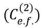
- Verfahren nach einem der Ansprüche 1 bis 5, wobei der angepasste Bremssollwert

- Computerprogramm, das Anweisungen aufweist, um das Verfahren nach einem der Ansprüche 1 bis 6 auszuführen.
- Vorrichtung zur Anpassung einer Bremsung (18) für ein Fahrzeug, das mit einer Nutzbremseinrichtung und einer ergänzenden Bremseinrichtung ausgestattet ist, wobei die Vorrichtung angeordnet ist, einen Bremssollwert

- System zur Bremsaufteilung für ein Fahrzeug, das mit einer Nutzbremseinrichtung und einer ergänzenden Bremseinrichtung ausgestattet ist, umfassend
eine Vorrichtung zur Aufteilung (19) eines Bremsbefehls (CG) zwischen einem Nutzbremssollwert (Ce), der für die Nutzbremseinrichtung bestimmt ist, und einem Nutzwert einer ergänzenden Bremsung (Ch), der für die ergänzende Bremseinrichtung bestimmt ist, und
eine Vorrichtung zur Anpassung (18) des Nutzbremssollwerts nach Anspruch 8. - Kraftfahrzeug, das mit einer Nutzbremseinrichtung, einer ergänzenden Bremseinrichtung und einem System zur Bremsaufteilung nach Anspruch 9 ausgestattet ist.
Applications Claiming Priority (2)
| Application Number | Priority Date | Filing Date | Title |
|---|---|---|---|
| FR1159106A FR2981033B1 (fr) | 2011-10-10 | 2011-10-10 | Adaptation d'une consigne de freinage regeneratif |
| PCT/FR2012/052292 WO2013054034A2 (fr) | 2011-10-10 | 2012-10-09 | Adaptation d'une consigne de freinage regeneratif |
Publications (2)
| Publication Number | Publication Date |
|---|---|
| EP2766232A2 EP2766232A2 (de) | 2014-08-20 |
| EP2766232B1 true EP2766232B1 (de) | 2018-05-16 |
Family
ID=47143162
Family Applications (1)
| Application Number | Title | Priority Date | Filing Date |
|---|---|---|---|
| EP12781381.4A Not-in-force EP2766232B1 (de) | 2011-10-10 | 2012-10-09 | Sollwertanpassung für eine nutzbremsung |
Country Status (5)
| Country | Link |
|---|---|
| US (1) | US9421870B2 (de) |
| EP (1) | EP2766232B1 (de) |
| CN (1) | CN103974862B (de) |
| FR (1) | FR2981033B1 (de) |
| WO (1) | WO2013054034A2 (de) |
Families Citing this family (2)
| Publication number | Priority date | Publication date | Assignee | Title |
|---|---|---|---|---|
| DE102013205314B4 (de) * | 2013-03-26 | 2016-09-29 | Continental Automotive Gmbh | Verfahren zum Betreiben einer Rekuperationsbremseinrichtung eines Kraftfahrzeugs und Rekuperationsbremseinrichtung für ein Kraftfahrzeug |
| DE102014203751A1 (de) * | 2014-02-28 | 2015-09-03 | Siemens Aktiengesellschaft | Fahrzeug, insbesondere Schienenfahrzeug, mit Bremsvermögensberechnungsmöglichkeit und Verfahren zu dessen Betrieb |
Family Cites Families (15)
| Publication number | Priority date | Publication date | Assignee | Title |
|---|---|---|---|---|
| FR1058539A (fr) | 1952-06-19 | 1954-03-17 | Csf | Perfectionnements aux dispositifs de duplexage |
| FR1153410A (fr) | 1953-12-04 | 1958-03-10 | Matière de liaison pour matériaux de construction et son mode de fabrication | |
| US6445982B1 (en) * | 2001-03-26 | 2002-09-03 | Visteon Global Technologies, Inc. | Regenerative deceleration for a hybrid drive system |
| JP4058932B2 (ja) * | 2001-10-25 | 2008-03-12 | トヨタ自動車株式会社 | 車輌用制動制御装置 |
| JP4147976B2 (ja) * | 2002-09-13 | 2008-09-10 | 日産自動車株式会社 | 複合ブレーキの協調制御装置 |
| US8066339B2 (en) * | 2004-03-09 | 2011-11-29 | Ford Global Technologies, Llc | Vehicle and method for controlling regenerative braking |
| WO2005110827A1 (de) * | 2004-05-03 | 2005-11-24 | Continental Teves Ag & Co. Ohg | Verfahren für die steuerung eines bremssystems eines kraftfahrzeuges |
| US20050269875A1 (en) * | 2004-06-08 | 2005-12-08 | Kazuya Maki | Vehicle brake device |
| EP2084043B1 (de) * | 2006-11-29 | 2015-01-14 | Continental Teves AG & Co. oHG | Vorrichtung zur bestimmung eines fahrzustandes und verfahren zum fahrzustandabhängigen betrieb einer kombinierten fahrzeugbremsanlage |
| DE102006058565A1 (de) * | 2006-12-12 | 2008-06-19 | Siemens Ag | Ausgeglichene Keilregelung |
| FR2917694B1 (fr) * | 2007-06-21 | 2009-08-21 | Renault Sas | Procede de controle du freinage recuperatif pour vehicule hybride et/ou a quatre roues motrices et arrangement pour vehicule mettant en oeuvre le procede |
| US8135526B2 (en) | 2007-11-03 | 2012-03-13 | GM Global Technology Operations LLC | Method for controlling regenerative braking and friction braking |
| JP5184406B2 (ja) * | 2009-03-11 | 2013-04-17 | 富士重工業株式会社 | 電気自動車の制御装置 |
| DE102010040657A1 (de) * | 2010-09-13 | 2012-03-15 | Robert Bosch Gmbh | Bremssystem für ein Fahrzeug |
| US9493148B2 (en) * | 2011-04-13 | 2016-11-15 | Ford Global Technologies, Llc | Torque modulation in a hybrid vehicle downshift during regenerative braking |
-
2011
- 2011-10-10 FR FR1159106A patent/FR2981033B1/fr not_active Expired - Fee Related
-
2012
- 2012-10-09 US US14/350,701 patent/US9421870B2/en not_active Expired - Fee Related
- 2012-10-09 CN CN201280060554.XA patent/CN103974862B/zh not_active Expired - Fee Related
- 2012-10-09 WO PCT/FR2012/052292 patent/WO2013054034A2/fr not_active Ceased
- 2012-10-09 EP EP12781381.4A patent/EP2766232B1/de not_active Not-in-force
Non-Patent Citations (1)
| Title |
|---|
| None * |
Also Published As
| Publication number | Publication date |
|---|---|
| FR2981033A1 (fr) | 2013-04-12 |
| WO2013054034A3 (fr) | 2013-10-24 |
| CN103974862B (zh) | 2016-10-12 |
| WO2013054034A2 (fr) | 2013-04-18 |
| US20140257663A1 (en) | 2014-09-11 |
| US9421870B2 (en) | 2016-08-23 |
| EP2766232A2 (de) | 2014-08-20 |
| CN103974862A (zh) | 2014-08-06 |
| FR2981033B1 (fr) | 2014-04-04 |
Similar Documents
| Publication | Publication Date | Title |
|---|---|---|
| EP2139740B1 (de) | Unterstützungssystem zum befahren von steigungen für automobile | |
| EP3030449B1 (de) | Regelung der regenerativen bremsung in einem elektro- oder hybridfahrzeug | |
| FR2964625A1 (fr) | Systemes et procedes pour un freinage dynamiquement stable | |
| EP1732794B1 (de) | Abwärtsfahrhilfeverfahren und entsprechende vorrichtung | |
| WO2012110736A2 (fr) | Systeme et procede de freinage d'un vehicule a traction electrique ou hybride | |
| EP3030447B1 (de) | Regelung der regenerativen bremsung in einem elektro- oder hybridfahrzeug | |
| EP2870051A1 (de) | Verfahren zur zentrierung des lenkrads einer servolenkung eines kraftfahrzeugs | |
| EP2307253B1 (de) | Vorrichtung zur bestimmung der querbeschleunigung eines motorfahrzeugs und entsprechendes verfahren | |
| EP2900541B1 (de) | Servolenkungsverwaltung für ein kraftfahrzeug | |
| FR2946602A1 (fr) | Procede de commande d'un systeme de freinage. | |
| WO2013054034A2 (fr) | Adaptation d'une consigne de freinage regeneratif | |
| WO2013083525A1 (fr) | Controle du freinage | |
| EP2776270B1 (de) | Anpassung eines simulierten motorbremsbefehls | |
| FR2896467A1 (fr) | Procede d'estimation de la vitesse longitudinale d'un vehicule automobile | |
| EP2082939A2 (de) | Verfahren und System zur Abschätzung der Haftung in einem Kraftfahrzeug | |
| FR2977538A1 (fr) | Simulation de freinage moteur | |
| EP3730385A1 (de) | Verfahren und vorrichtung zur erkennung und minderung von geschwindigkeitsabweichungen eines kraftfahrzeugs, die in ein einparkhilfssystem integriert ist | |
| WO2010125290A1 (fr) | Procede d'aide au controle de la trajectoire d'un vehicule automobile | |
| FR2939389A3 (fr) | Procede de regulation de la vitesse d'un vehicule automobile entraine par la gravitation dans une pente | |
| FR3040159A1 (fr) | Procede de controle d'un groupe motopropulseur electrique ou hybride | |
| FR2934544A3 (fr) | Procede de freinage agissant sur les roues d'un vehicule automobile | |
| FR2934543A3 (fr) | Procede de freinage agissant sur les roues d'un vehicule automobile |
Legal Events
| Date | Code | Title | Description |
|---|---|---|---|
| PUAI | Public reference made under article 153(3) epc to a published international application that has entered the european phase |
Free format text: ORIGINAL CODE: 0009012 |
|
| 17P | Request for examination filed |
Effective date: 20140327 |
|
| AK | Designated contracting states |
Kind code of ref document: A2 Designated state(s): AL AT BE BG CH CY CZ DE DK EE ES FI FR GB GR HR HU IE IS IT LI LT LU LV MC MK MT NL NO PL PT RO RS SE SI SK SM TR |
|
| DAX | Request for extension of the european patent (deleted) | ||
| GRAP | Despatch of communication of intention to grant a patent |
Free format text: ORIGINAL CODE: EPIDOSNIGR1 |
|
| STAA | Information on the status of an ep patent application or granted ep patent |
Free format text: STATUS: GRANT OF PATENT IS INTENDED |
|
| INTG | Intention to grant announced |
Effective date: 20171211 |
|
| GRAS | Grant fee paid |
Free format text: ORIGINAL CODE: EPIDOSNIGR3 |
|
| GRAA | (expected) grant |
Free format text: ORIGINAL CODE: 0009210 |
|
| STAA | Information on the status of an ep patent application or granted ep patent |
Free format text: STATUS: THE PATENT HAS BEEN GRANTED |
|
| AK | Designated contracting states |
Kind code of ref document: B1 Designated state(s): AL AT BE BG CH CY CZ DE DK EE ES FI FR GB GR HR HU IE IS IT LI LT LU LV MC MK MT NL NO PL PT RO RS SE SI SK SM TR |
|
| REG | Reference to a national code |
Ref country code: GB Ref legal event code: FG4D Free format text: NOT ENGLISH |
|
| REG | Reference to a national code |
Ref country code: CH Ref legal event code: EP |
|
| REG | Reference to a national code |
Ref country code: IE Ref legal event code: FG4D Free format text: LANGUAGE OF EP DOCUMENT: FRENCH |
|
| REG | Reference to a national code |
Ref country code: DE Ref legal event code: R096 Ref document number: 602012046421 Country of ref document: DE |
|
| REG | Reference to a national code |
Ref country code: AT Ref legal event code: REF Ref document number: 999256 Country of ref document: AT Kind code of ref document: T Effective date: 20180615 |
|
| REG | Reference to a national code |
Ref country code: NL Ref legal event code: MP Effective date: 20180516 |
|
| REG | Reference to a national code |
Ref country code: LT Ref legal event code: MG4D |
|
| REG | Reference to a national code |
Ref country code: FR Ref legal event code: PLFP Year of fee payment: 7 |
|
| PG25 | Lapsed in a contracting state [announced via postgrant information from national office to epo] |
Ref country code: NO Free format text: LAPSE BECAUSE OF FAILURE TO SUBMIT A TRANSLATION OF THE DESCRIPTION OR TO PAY THE FEE WITHIN THE PRESCRIBED TIME-LIMIT Effective date: 20180816 Ref country code: FI Free format text: LAPSE BECAUSE OF FAILURE TO SUBMIT A TRANSLATION OF THE DESCRIPTION OR TO PAY THE FEE WITHIN THE PRESCRIBED TIME-LIMIT Effective date: 20180516 Ref country code: BG Free format text: LAPSE BECAUSE OF FAILURE TO SUBMIT A TRANSLATION OF THE DESCRIPTION OR TO PAY THE FEE WITHIN THE PRESCRIBED TIME-LIMIT Effective date: 20180816 Ref country code: SE Free format text: LAPSE BECAUSE OF FAILURE TO SUBMIT A TRANSLATION OF THE DESCRIPTION OR TO PAY THE FEE WITHIN THE PRESCRIBED TIME-LIMIT Effective date: 20180516 Ref country code: ES Free format text: LAPSE BECAUSE OF FAILURE TO SUBMIT A TRANSLATION OF THE DESCRIPTION OR TO PAY THE FEE WITHIN THE PRESCRIBED TIME-LIMIT Effective date: 20180516 Ref country code: LT Free format text: LAPSE BECAUSE OF FAILURE TO SUBMIT A TRANSLATION OF THE DESCRIPTION OR TO PAY THE FEE WITHIN THE PRESCRIBED TIME-LIMIT Effective date: 20180516 |
|
| PG25 | Lapsed in a contracting state [announced via postgrant information from national office to epo] |
Ref country code: LV Free format text: LAPSE BECAUSE OF FAILURE TO SUBMIT A TRANSLATION OF THE DESCRIPTION OR TO PAY THE FEE WITHIN THE PRESCRIBED TIME-LIMIT Effective date: 20180516 Ref country code: HR Free format text: LAPSE BECAUSE OF FAILURE TO SUBMIT A TRANSLATION OF THE DESCRIPTION OR TO PAY THE FEE WITHIN THE PRESCRIBED TIME-LIMIT Effective date: 20180516 Ref country code: NL Free format text: LAPSE BECAUSE OF FAILURE TO SUBMIT A TRANSLATION OF THE DESCRIPTION OR TO PAY THE FEE WITHIN THE PRESCRIBED TIME-LIMIT Effective date: 20180516 Ref country code: GR Free format text: LAPSE BECAUSE OF FAILURE TO SUBMIT A TRANSLATION OF THE DESCRIPTION OR TO PAY THE FEE WITHIN THE PRESCRIBED TIME-LIMIT Effective date: 20180817 Ref country code: RS Free format text: LAPSE BECAUSE OF FAILURE TO SUBMIT A TRANSLATION OF THE DESCRIPTION OR TO PAY THE FEE WITHIN THE PRESCRIBED TIME-LIMIT Effective date: 20180516 |
|
| REG | Reference to a national code |
Ref country code: AT Ref legal event code: MK05 Ref document number: 999256 Country of ref document: AT Kind code of ref document: T Effective date: 20180516 |
|
| PG25 | Lapsed in a contracting state [announced via postgrant information from national office to epo] |
Ref country code: PL Free format text: LAPSE BECAUSE OF FAILURE TO SUBMIT A TRANSLATION OF THE DESCRIPTION OR TO PAY THE FEE WITHIN THE PRESCRIBED TIME-LIMIT Effective date: 20180516 Ref country code: DK Free format text: LAPSE BECAUSE OF FAILURE TO SUBMIT A TRANSLATION OF THE DESCRIPTION OR TO PAY THE FEE WITHIN THE PRESCRIBED TIME-LIMIT Effective date: 20180516 Ref country code: EE Free format text: LAPSE BECAUSE OF FAILURE TO SUBMIT A TRANSLATION OF THE DESCRIPTION OR TO PAY THE FEE WITHIN THE PRESCRIBED TIME-LIMIT Effective date: 20180516 Ref country code: AT Free format text: LAPSE BECAUSE OF FAILURE TO SUBMIT A TRANSLATION OF THE DESCRIPTION OR TO PAY THE FEE WITHIN THE PRESCRIBED TIME-LIMIT Effective date: 20180516 Ref country code: RO Free format text: LAPSE BECAUSE OF FAILURE TO SUBMIT A TRANSLATION OF THE DESCRIPTION OR TO PAY THE FEE WITHIN THE PRESCRIBED TIME-LIMIT Effective date: 20180516 Ref country code: CZ Free format text: LAPSE BECAUSE OF FAILURE TO SUBMIT A TRANSLATION OF THE DESCRIPTION OR TO PAY THE FEE WITHIN THE PRESCRIBED TIME-LIMIT Effective date: 20180516 Ref country code: SK Free format text: LAPSE BECAUSE OF FAILURE TO SUBMIT A TRANSLATION OF THE DESCRIPTION OR TO PAY THE FEE WITHIN THE PRESCRIBED TIME-LIMIT Effective date: 20180516 |
|
| REG | Reference to a national code |
Ref country code: DE Ref legal event code: R097 Ref document number: 602012046421 Country of ref document: DE |
|
| PG25 | Lapsed in a contracting state [announced via postgrant information from national office to epo] |
Ref country code: SM Free format text: LAPSE BECAUSE OF FAILURE TO SUBMIT A TRANSLATION OF THE DESCRIPTION OR TO PAY THE FEE WITHIN THE PRESCRIBED TIME-LIMIT Effective date: 20180516 Ref country code: IT Free format text: LAPSE BECAUSE OF FAILURE TO SUBMIT A TRANSLATION OF THE DESCRIPTION OR TO PAY THE FEE WITHIN THE PRESCRIBED TIME-LIMIT Effective date: 20180516 |
|
| PLBE | No opposition filed within time limit |
Free format text: ORIGINAL CODE: 0009261 |
|
| STAA | Information on the status of an ep patent application or granted ep patent |
Free format text: STATUS: NO OPPOSITION FILED WITHIN TIME LIMIT |
|
| 26N | No opposition filed |
Effective date: 20190219 |
|
| PG25 | Lapsed in a contracting state [announced via postgrant information from national office to epo] |
Ref country code: SI Free format text: LAPSE BECAUSE OF FAILURE TO SUBMIT A TRANSLATION OF THE DESCRIPTION OR TO PAY THE FEE WITHIN THE PRESCRIBED TIME-LIMIT Effective date: 20180516 |
|
| REG | Reference to a national code |
Ref country code: CH Ref legal event code: PL |
|
| REG | Reference to a national code |
Ref country code: BE Ref legal event code: MM Effective date: 20181031 |
|
| PG25 | Lapsed in a contracting state [announced via postgrant information from national office to epo] |
Ref country code: MC Free format text: LAPSE BECAUSE OF FAILURE TO SUBMIT A TRANSLATION OF THE DESCRIPTION OR TO PAY THE FEE WITHIN THE PRESCRIBED TIME-LIMIT Effective date: 20180516 Ref country code: LU Free format text: LAPSE BECAUSE OF NON-PAYMENT OF DUE FEES Effective date: 20181009 |
|
| REG | Reference to a national code |
Ref country code: IE Ref legal event code: MM4A |
|
| PG25 | Lapsed in a contracting state [announced via postgrant information from national office to epo] |
Ref country code: BE Free format text: LAPSE BECAUSE OF NON-PAYMENT OF DUE FEES Effective date: 20181031 Ref country code: CH Free format text: LAPSE BECAUSE OF NON-PAYMENT OF DUE FEES Effective date: 20181031 Ref country code: LI Free format text: LAPSE BECAUSE OF NON-PAYMENT OF DUE FEES Effective date: 20181031 |
|
| PG25 | Lapsed in a contracting state [announced via postgrant information from national office to epo] |
Ref country code: IE Free format text: LAPSE BECAUSE OF NON-PAYMENT OF DUE FEES Effective date: 20181009 |
|
| PG25 | Lapsed in a contracting state [announced via postgrant information from national office to epo] |
Ref country code: AL Free format text: LAPSE BECAUSE OF FAILURE TO SUBMIT A TRANSLATION OF THE DESCRIPTION OR TO PAY THE FEE WITHIN THE PRESCRIBED TIME-LIMIT Effective date: 20180516 |
|
| PG25 | Lapsed in a contracting state [announced via postgrant information from national office to epo] |
Ref country code: MT Free format text: LAPSE BECAUSE OF FAILURE TO SUBMIT A TRANSLATION OF THE DESCRIPTION OR TO PAY THE FEE WITHIN THE PRESCRIBED TIME-LIMIT Effective date: 20180516 |
|
| PG25 | Lapsed in a contracting state [announced via postgrant information from national office to epo] |
Ref country code: TR Free format text: LAPSE BECAUSE OF FAILURE TO SUBMIT A TRANSLATION OF THE DESCRIPTION OR TO PAY THE FEE WITHIN THE PRESCRIBED TIME-LIMIT Effective date: 20180516 |
|
| PG25 | Lapsed in a contracting state [announced via postgrant information from national office to epo] |
Ref country code: PT Free format text: LAPSE BECAUSE OF FAILURE TO SUBMIT A TRANSLATION OF THE DESCRIPTION OR TO PAY THE FEE WITHIN THE PRESCRIBED TIME-LIMIT Effective date: 20180516 |
|
| PG25 | Lapsed in a contracting state [announced via postgrant information from national office to epo] |
Ref country code: MK Free format text: LAPSE BECAUSE OF NON-PAYMENT OF DUE FEES Effective date: 20180516 Ref country code: CY Free format text: LAPSE BECAUSE OF FAILURE TO SUBMIT A TRANSLATION OF THE DESCRIPTION OR TO PAY THE FEE WITHIN THE PRESCRIBED TIME-LIMIT Effective date: 20180516 Ref country code: HU Free format text: LAPSE BECAUSE OF FAILURE TO SUBMIT A TRANSLATION OF THE DESCRIPTION OR TO PAY THE FEE WITHIN THE PRESCRIBED TIME-LIMIT; INVALID AB INITIO Effective date: 20121009 |
|
| PG25 | Lapsed in a contracting state [announced via postgrant information from national office to epo] |
Ref country code: IS Free format text: LAPSE BECAUSE OF FAILURE TO SUBMIT A TRANSLATION OF THE DESCRIPTION OR TO PAY THE FEE WITHIN THE PRESCRIBED TIME-LIMIT Effective date: 20180916 |
|
| PGFP | Annual fee paid to national office [announced via postgrant information from national office to epo] |
Ref country code: FR Payment date: 20221031 Year of fee payment: 11 |
|
| PGFP | Annual fee paid to national office [announced via postgrant information from national office to epo] |
Ref country code: GB Payment date: 20221020 Year of fee payment: 11 Ref country code: DE Payment date: 20221019 Year of fee payment: 11 |
|
| P01 | Opt-out of the competence of the unified patent court (upc) registered |
Effective date: 20230608 |
|
| REG | Reference to a national code |
Ref country code: DE Ref legal event code: R119 Ref document number: 602012046421 Country of ref document: DE |
|
| GBPC | Gb: european patent ceased through non-payment of renewal fee |
Effective date: 20231009 |
|
| PG25 | Lapsed in a contracting state [announced via postgrant information from national office to epo] |
Ref country code: GB Free format text: LAPSE BECAUSE OF NON-PAYMENT OF DUE FEES Effective date: 20231009 |
|
| PG25 | Lapsed in a contracting state [announced via postgrant information from national office to epo] |
Ref country code: GB Free format text: LAPSE BECAUSE OF NON-PAYMENT OF DUE FEES Effective date: 20231009 Ref country code: FR Free format text: LAPSE BECAUSE OF NON-PAYMENT OF DUE FEES Effective date: 20231031 Ref country code: DE Free format text: LAPSE BECAUSE OF NON-PAYMENT OF DUE FEES Effective date: 20240501 |