EP2767355A1 - Noyau segmenté et procédé de moulage d'une roue - Google Patents
Noyau segmenté et procédé de moulage d'une roue Download PDFInfo
- Publication number
- EP2767355A1 EP2767355A1 EP13155624.3A EP13155624A EP2767355A1 EP 2767355 A1 EP2767355 A1 EP 2767355A1 EP 13155624 A EP13155624 A EP 13155624A EP 2767355 A1 EP2767355 A1 EP 2767355A1
- Authority
- EP
- European Patent Office
- Prior art keywords
- core
- segments
- impeller
- moulding
- segmented
- Prior art date
- Legal status (The legal status is an assumption and is not a legal conclusion. Google has not performed a legal analysis and makes no representation as to the accuracy of the status listed.)
- Granted
Links
Images


Classifications
-
- B—PERFORMING OPERATIONS; TRANSPORTING
- B22—CASTING; POWDER METALLURGY
- B22C—FOUNDRY MOULDING
- B22C9/00—Moulds or cores; Moulding processes
- B22C9/10—Cores; Manufacture or installation of cores
- B22C9/103—Multipart cores
-
- B—PERFORMING OPERATIONS; TRANSPORTING
- B22—CASTING; POWDER METALLURGY
- B22F—WORKING METALLIC POWDER; MANUFACTURE OF ARTICLES FROM METALLIC POWDER; MAKING METALLIC POWDER; APPARATUS OR DEVICES SPECIALLY ADAPTED FOR METALLIC POWDER
- B22F3/00—Manufacture of workpieces or articles from metallic powder characterised by the manner of compacting or sintering; Apparatus specially adapted therefor ; Presses and furnaces
- B22F3/22—Manufacture of workpieces or articles from metallic powder characterised by the manner of compacting or sintering; Apparatus specially adapted therefor ; Presses and furnaces for producing castings from a slip
- B22F3/225—Manufacture of workpieces or articles from metallic powder characterised by the manner of compacting or sintering; Apparatus specially adapted therefor ; Presses and furnaces for producing castings from a slip by injection molding
-
- B—PERFORMING OPERATIONS; TRANSPORTING
- B22—CASTING; POWDER METALLURGY
- B22F—WORKING METALLIC POWDER; MANUFACTURE OF ARTICLES FROM METALLIC POWDER; MAKING METALLIC POWDER; APPARATUS OR DEVICES SPECIALLY ADAPTED FOR METALLIC POWDER
- B22F7/00—Manufacture of composite layers, workpieces, or articles, comprising metallic powder, by sintering the powder, with or without compacting wherein at least one part is obtained by sintering or compression
- B22F7/06—Manufacture of composite layers, workpieces, or articles, comprising metallic powder, by sintering the powder, with or without compacting wherein at least one part is obtained by sintering or compression of composite workpieces or articles from parts, e.g. to form tipped tools
-
- B—PERFORMING OPERATIONS; TRANSPORTING
- B29—WORKING OF PLASTICS; WORKING OF SUBSTANCES IN A PLASTIC STATE IN GENERAL
- B29C—SHAPING OR JOINING OF PLASTICS; SHAPING OF MATERIAL IN A PLASTIC STATE, NOT OTHERWISE PROVIDED FOR; AFTER-TREATMENT OF THE SHAPED PRODUCTS, e.g. REPAIRING
- B29C33/00—Moulds or cores; Details thereof or accessories therefor
- B29C33/0033—Moulds or cores; Details thereof or accessories therefor constructed for making articles provided with holes
-
- B—PERFORMING OPERATIONS; TRANSPORTING
- B29—WORKING OF PLASTICS; WORKING OF SUBSTANCES IN A PLASTIC STATE IN GENERAL
- B29C—SHAPING OR JOINING OF PLASTICS; SHAPING OF MATERIAL IN A PLASTIC STATE, NOT OTHERWISE PROVIDED FOR; AFTER-TREATMENT OF THE SHAPED PRODUCTS, e.g. REPAIRING
- B29C33/00—Moulds or cores; Details thereof or accessories therefor
- B29C33/76—Cores
-
- B—PERFORMING OPERATIONS; TRANSPORTING
- B29—WORKING OF PLASTICS; WORKING OF SUBSTANCES IN A PLASTIC STATE IN GENERAL
- B29C—SHAPING OR JOINING OF PLASTICS; SHAPING OF MATERIAL IN A PLASTIC STATE, NOT OTHERWISE PROVIDED FOR; AFTER-TREATMENT OF THE SHAPED PRODUCTS, e.g. REPAIRING
- B29C45/00—Injection moulding, i.e. forcing the required volume of moulding material through a nozzle into a closed mould; Apparatus therefor
- B29C45/17—Component parts, details or accessories; Auxiliary operations
- B29C45/40—Removing or ejecting moulded articles
-
- F—MECHANICAL ENGINEERING; LIGHTING; HEATING; WEAPONS; BLASTING
- F04—POSITIVE - DISPLACEMENT MACHINES FOR LIQUIDS; PUMPS FOR LIQUIDS OR ELASTIC FLUIDS
- F04D—NON-POSITIVE-DISPLACEMENT PUMPS
- F04D29/00—Details, component parts, or accessories
- F04D29/18—Rotors
- F04D29/22—Rotors specially for centrifugal pumps
- F04D29/2205—Conventional flow pattern
- F04D29/2222—Construction and assembly
-
- B—PERFORMING OPERATIONS; TRANSPORTING
- B22—CASTING; POWDER METALLURGY
- B22C—FOUNDRY MOULDING
- B22C9/00—Moulds or cores; Moulding processes
- B22C9/10—Cores; Manufacture or installation of cores
-
- B—PERFORMING OPERATIONS; TRANSPORTING
- B29—WORKING OF PLASTICS; WORKING OF SUBSTANCES IN A PLASTIC STATE IN GENERAL
- B29K—INDEXING SCHEME ASSOCIATED WITH SUBCLASSES B29B, B29C OR B29D, RELATING TO MOULDING MATERIALS OR TO MATERIALS FOR MOULDS, REINFORCEMENTS, FILLERS OR PREFORMED PARTS, e.g. INSERTS
- B29K2859/00—Use of polyacetals, e.g. POM, i.e. polyoxymethylene, or derivatives thereof as mould material
-
- B—PERFORMING OPERATIONS; TRANSPORTING
- B29—WORKING OF PLASTICS; WORKING OF SUBSTANCES IN A PLASTIC STATE IN GENERAL
- B29K—INDEXING SCHEME ASSOCIATED WITH SUBCLASSES B29B, B29C OR B29D, RELATING TO MOULDING MATERIALS OR TO MATERIALS FOR MOULDS, REINFORCEMENTS, FILLERS OR PREFORMED PARTS, e.g. INSERTS
- B29K2905/00—Use of metals, their alloys or their compounds, as mould material
- B29K2905/06—Tin
-
- B—PERFORMING OPERATIONS; TRANSPORTING
- B29—WORKING OF PLASTICS; WORKING OF SUBSTANCES IN A PLASTIC STATE IN GENERAL
- B29L—INDEXING SCHEME ASSOCIATED WITH SUBCLASS B29C, RELATING TO PARTICULAR ARTICLES
- B29L2031/00—Other particular articles
- B29L2031/08—Blades for rotors, stators, fans, turbines or the like, e.g. screw propellers
Definitions
- the invention relates to a segmented core for moulding of an impeller and a method for moulding an impeller.
- impellers are used for a variety of applications.
- impellers may be used as a rotating component in pumps as, e.g., centrifugal pumps, for transferring energy from a motor that drives the pump to a fluid being pumped.
- impellers are made from metal and are configured as short cylinders with an inlet for incoming fluid, vanes for pushing the fluid radially, and a bore to accept a drive shaft.
- Impellers nowadays are made from plastic material by injection moulding. Impellers made of metal can be produced by casting or by welding metal sheets. Both methods are expensive.
- MIM metal injection moulding
- the present invention is based on the object to provide a segmented core to be used for moulding an impeller, and a method for moulding an impeller which allow an impeller to be made by a MIM process and still allowing for a high design freedom to realize complex shapes.
- a segmented core for moulding of an impeller especially a pump impeller
- a segmented core for moulding of an impeller comprising at least three segments, all segments having the same form and each segment having connecting means for connecting the segment with the adjacent segments.
- segmenting the core into connectable elements it is possible to have free access to each side of each segment during the moulding process. This is necessary for forming the impeller since it is technically impossible to mould the different three dimensional segments in one-piece.
- two segments border the room for a blade of the impeller in the mould.
- the core has an inner ring and an outer ring.
- the inner and/or outer rings of the core are destined for positioning the core in the moulding tool which allows an easy handling of the core during the moulding process.
- connection means of the segments are formed as self-locking parts of the inner and outer rings of the core. This also contributes to an easy handling and assembly of the core during the moulding process.
- connection means of the segments may preferably be formed as snap-locking parts which allow for an easy and reliable connection of the segments.
- the segments may be nested and/or tensed up jointly.
- the segments are injection moulded which is a very cost effective method and which, moreover, is suited for mass production.
- the segments may consist of a thermoplastic polymer, in particular, of polyoxymethylene (POM).
- POM polyoxymethylene
- a method for moulding an impeller with the following steps: Providing a moulding tool, providing a core consisting of at least 3 identical segments, which comprise connection means for connecting the segment with the adjacent segments, assembling of the core and placing the core in the moulding tool, moulding the impeller, and ejecting core and impeller out of the moulding tool, removing the core from the impeller.
- the inventive method allows for an impeller to be formed in a moulding process with a complex three dimensional shape.
- the core may be chemically and/or thermally removed.
- the core segments are made by injection moulding and especially by moulding a thermoplastic polymer or a tin/bismuth alloy.
- the impeller may be made by injection moulding and especially metal injection moulding (MIM) which process is well suited for mass production and which is very economical.
- MIM metal injection moulding
- the impeller is baked-out, preferably sintered, after removing the core. This provides the desired properties for the thus finished impeller.
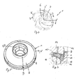
- Fig. 1A and 1B are respective views of a segmented core 1 according to an embodiment of the invention.
- Fig. 1A is a perspective view of the segmented core 1 with one segment 2 removed
- Fig. 1B is a partial sectional view of the segmented core 1.
- the segmented core of the embodiment consists of six single segments 2 which are connected to each other by connecting means 3.
- first connecting means 3 arranged at an outer portion 4 of each segment 2 whereby the outer portions 4 of all segments 2 together form an outer ring 5
- one second connecting means 3' provided at an inner portion 6 of each segment 2 whereby the inner portions 6 of all segments 2 together form an inner ring 7.
- connection means 3, 3' of the segments 2 are formed as self-locking parts of the inner and outer rings 5, 7 of the core 1.
- the connection means 3, 3' of the segments 2 are formed as snap-locking parts.
- the inner ring 5 and the outer ring 7 of the core 1 are positioning aids for positioning the core 2 in a moulding tool.
- each two adjacent segments 2 define and delimit the space for a blade of the impeller to be formed in a further process step in the mould by metal injection moulding.
- the segments 2 are also injection moulded and consist of a thermoplastic polymer, specifically, of polyoxymethylene (POM).
- Fig. 2 is a perspective view of a isolated single segment 2 of the segmented core 1 shown in Fig. 1A and 1B .
- each segment 2 comprises the two first connecting means 2 at the outer portion 4 and one connecting means 3' at the inner portion 6 which all are formed as self-locking means and are configured to engage with correspondingly formed connecting means 3, 3' or neighbouring segments 2 when the core 1 is assembled.
- Fig.3 is a perspective view of preassembled segments 2 of the segmented core 1 shown in Fig. 1A and 1B .
- the core 1 which consists of six segments 2
- three segments 2 are preassembled by respectively connecting them via their respective connecting means 3, 3'.
- the two halves of the core 1 each consisting of three segments 2 will be assembled to form a complete core 1.
- these are connected to each other by "sliding" them together.
- Fig. 4 is a sectional view of a part of the segmented core 1 with MIM feedstock 8 moulded around the core 1 in the moulding tool 14.
- the segments 2 When placed in the moulding tool 14, the segments 2 have been assembled as described above in connection with Fig. 3 .
- the segmented core 2 acts as an inner moulding part and the MIM feedstock 8 is moulded on the outside of the core 1.
- the number of segments 2 of the core 1 represents the internal geometry of the impeller to be produced. As the number of segments 2 in the embodiment shown is six, the number of vanes or blades of the impeller to be produced will also be six. Further, as can be seen in Fig.
- supports 10 since it is essential that the segments 2 are sufficiently supported when loaded, there are provided supports 10. Also, larger segments 2 may have the tendency to deflect during insert moulding as a function of the injection pressure and thermal influence from the feedstock 8. To prevent this, ejectors 11 are provided which help to support the segments 2 during injection and retract these during the holding time. For larger MIM parts, there could be a critical parameter in the difference in thermal expansion between the MIM feedstock 8 and the segments 2. This would eventually generate cracks during de-binding due to the difference in thermal expansion. This can be avoided partially by heating the segments before the insert moulding in order to compensate for this expansion.
- Fig. 5 is a perspective view of a metal injection moulded (MIM) feedstock 8 moulded around the segmented core 1 without the moulding tool.
- the feedstock 8 covers the segmented core 1 from the top and is engaged at its outer circumference by the outer ring 5 of the segmented core 1.
- the inner ring 7 is fitted in an inner ring portion 9 of the feedstock 8.
- the segments 2 of the core 1 are moulded in POM which is the main component of the binder system of the MIM feedstock 8 and which is the component which will react with the HNO 3 in the de-binding process described below.
- Fig. 6A and 6B are respective views of a finished impeller 12 wherein Fig. 6A is a perspective view and Fig. 6B is another perspective view with a front part cut away so that the interior of the impeller 12 can be seen.
- the segments 2 of the segmented core 1 have been removed by a de-binding process which is a catalytic process in which the POM of the segments 2 reacts with HNO 3 whereby formaldehyde is created which can easily escape from the metal particles.
- the remaining feedstock then is subjected to a sintering process where after the finished impeller 12 is obtained.
- the interior of the impeller 12 in which the vanes or blades 13 are accommodated has a complex geometry. Nevertheless, the entire impeller 12 is formed as one metal injection moulded piece.
- the impeller 12 by a traditional injection moulding process using plastics.
- the inserted core 1 would normally be an alloy of Tin/Bismuth having a very low melting point.
- the latter For releasing the core from the moulded impeller 12, the latter would be placed in an oil bath having a predetermined temperature so that the core would melt and leave the impeller 12 with its internal geometry created by the thus formed hollow spaces.
Landscapes
- Engineering & Computer Science (AREA)
- Mechanical Engineering (AREA)
- Manufacturing & Machinery (AREA)
- General Engineering & Computer Science (AREA)
- Chemical & Material Sciences (AREA)
- Composite Materials (AREA)
- Materials Engineering (AREA)
- Structures Of Non-Positive Displacement Pumps (AREA)
- Injection Moulding Of Plastics Or The Like (AREA)
Priority Applications (4)
| Application Number | Priority Date | Filing Date | Title |
|---|---|---|---|
| EP13155624.3A EP2767355B1 (fr) | 2013-02-18 | 2013-02-18 | Noyau segmenté et procédé de moulage d'une roue |
| RU2015134547A RU2627069C2 (ru) | 2013-02-18 | 2014-02-04 | Сегментированный стержень и способ формования рабочего колеса |
| PCT/EP2014/052142 WO2014124837A1 (fr) | 2013-02-18 | 2014-02-04 | Âme segmentée et procédé de moulage d'une turbine |
| US14/768,277 US10016808B2 (en) | 2013-02-18 | 2014-02-04 | Segmented core and method for molding an impeller |
Applications Claiming Priority (1)
| Application Number | Priority Date | Filing Date | Title |
|---|---|---|---|
| EP13155624.3A EP2767355B1 (fr) | 2013-02-18 | 2013-02-18 | Noyau segmenté et procédé de moulage d'une roue |
Publications (2)
| Publication Number | Publication Date |
|---|---|
| EP2767355A1 true EP2767355A1 (fr) | 2014-08-20 |
| EP2767355B1 EP2767355B1 (fr) | 2021-03-10 |
Family
ID=47722125
Family Applications (1)
| Application Number | Title | Priority Date | Filing Date |
|---|---|---|---|
| EP13155624.3A Active EP2767355B1 (fr) | 2013-02-18 | 2013-02-18 | Noyau segmenté et procédé de moulage d'une roue |
Country Status (4)
| Country | Link |
|---|---|
| US (1) | US10016808B2 (fr) |
| EP (1) | EP2767355B1 (fr) |
| RU (1) | RU2627069C2 (fr) |
| WO (1) | WO2014124837A1 (fr) |
Cited By (2)
| Publication number | Priority date | Publication date | Assignee | Title |
|---|---|---|---|---|
| CN108000817A (zh) * | 2017-11-30 | 2018-05-08 | 重庆鑫际激光科技有限公司 | 旋转式零部件脱模模具 |
| KR102745017B1 (ko) * | 2024-07-09 | 2024-12-20 | 임인규 | 중자를 이용한 복잡한 형상의 주조품 제조방법 |
Families Citing this family (6)
| Publication number | Priority date | Publication date | Assignee | Title |
|---|---|---|---|---|
| EP3324052A1 (fr) * | 2016-11-18 | 2018-05-23 | Sogefi Air & Cooling (SAS) | Turbine de pompe à fluide |
| US11473589B2 (en) | 2018-05-18 | 2022-10-18 | Franklin Electric Co., Inc. | Impeller assemblies and method of making |
| EP4036417B1 (fr) | 2019-09-25 | 2026-04-08 | Assoma Inc. | Procédé de fabrication d'une roue en plastique tridimensionnelle pour pompe centrifuge et roue |
| CN110586874A (zh) * | 2019-10-28 | 2019-12-20 | 襄阳五二五泵业有限公司 | 一种整体式叶轮砂芯的制作方法 |
| US11326616B2 (en) * | 2019-12-27 | 2022-05-10 | Asia Vital Components Co., Ltd. | Disk-shaped fan impeller structure |
| CN121889230A (zh) * | 2023-09-15 | 2026-04-17 | 盖瑞特动力科技(上海)有限公司 | 带罩叶轮制造方法 |
Citations (3)
| Publication number | Priority date | Publication date | Assignee | Title |
|---|---|---|---|---|
| EP0205105A1 (fr) * | 1985-06-10 | 1986-12-17 | Baker Hughes Incorporated | Noyau pour la fabrication de roues à aubes centrifuges en élastomère |
| US5591466A (en) * | 1994-01-14 | 1997-01-07 | Freudenberg-Nok General Partnership | Apparatus for making multi-segment plastic components |
| US20110262282A1 (en) * | 2008-12-24 | 2011-10-27 | Grundfos Management A/S | Method for injection molding a pump impeller and pump impeller |
Family Cites Families (11)
| Publication number | Priority date | Publication date | Assignee | Title |
|---|---|---|---|---|
| US4231413A (en) * | 1979-02-27 | 1980-11-04 | Graham Bretzger | Assembly for and method of making mold and casting of one-piece impellers |
| JPS5668548A (en) | 1979-11-06 | 1981-06-09 | Kubota Ltd | Casting method of impeller for axial-flow and oblique- flow pump |
| US4243199A (en) | 1979-12-05 | 1981-01-06 | Hill Rodman K | Mold for molding propellers having tapered hubs |
| JP3232333B2 (ja) | 1992-12-18 | 2001-11-26 | 川崎重工業株式会社 | インペラ鋳造用鋳型 |
| US5705204A (en) | 1993-03-17 | 1998-01-06 | Mtu Motoren- Und Turbinen-Union Friedrichshafen Gmbh | Model for a casting mold |
| JPH06328192A (ja) | 1993-05-21 | 1994-11-29 | Ebara Corp | ポンプインペラの鋳型製造方法 |
| KR100984464B1 (ko) * | 2002-03-26 | 2010-09-30 | 도레이 카부시키가이샤 | 열가소성 중합체, 그의 제조 방법 및 성형품 |
| RU2359778C1 (ru) | 2007-10-01 | 2009-06-27 | "Центр Разработки Нефтедобывающего Оборудования (Црно)" | Составной стержень для литья рабочих органов центробежных насосов с лопатками двойной кривизны и способ его изготовления |
| US7883662B2 (en) * | 2007-11-15 | 2011-02-08 | Viper Technologies | Metal injection molding methods and feedstocks |
| CN101658900B (zh) | 2009-09-24 | 2011-04-20 | 广东省佛山水泵厂有限公司 | 制作叶轮芯的方法 |
| IT1397058B1 (it) * | 2009-11-23 | 2012-12-28 | Nuovo Pignone Spa | Stampo per girante centrifuga, inserti per stampo e metodo per costruire una girante centrifuga |
-
2013
- 2013-02-18 EP EP13155624.3A patent/EP2767355B1/fr active Active
-
2014
- 2014-02-04 RU RU2015134547A patent/RU2627069C2/ru active
- 2014-02-04 WO PCT/EP2014/052142 patent/WO2014124837A1/fr not_active Ceased
- 2014-02-04 US US14/768,277 patent/US10016808B2/en active Active
Patent Citations (3)
| Publication number | Priority date | Publication date | Assignee | Title |
|---|---|---|---|---|
| EP0205105A1 (fr) * | 1985-06-10 | 1986-12-17 | Baker Hughes Incorporated | Noyau pour la fabrication de roues à aubes centrifuges en élastomère |
| US5591466A (en) * | 1994-01-14 | 1997-01-07 | Freudenberg-Nok General Partnership | Apparatus for making multi-segment plastic components |
| US20110262282A1 (en) * | 2008-12-24 | 2011-10-27 | Grundfos Management A/S | Method for injection molding a pump impeller and pump impeller |
Cited By (3)
| Publication number | Priority date | Publication date | Assignee | Title |
|---|---|---|---|---|
| CN108000817A (zh) * | 2017-11-30 | 2018-05-08 | 重庆鑫际激光科技有限公司 | 旋转式零部件脱模模具 |
| CN108000817B (zh) * | 2017-11-30 | 2019-07-30 | 重庆鑫际激光科技有限公司 | 旋转式零部件脱模模具 |
| KR102745017B1 (ko) * | 2024-07-09 | 2024-12-20 | 임인규 | 중자를 이용한 복잡한 형상의 주조품 제조방법 |
Also Published As
| Publication number | Publication date |
|---|---|
| US10016808B2 (en) | 2018-07-10 |
| RU2015134547A (ru) | 2017-03-29 |
| RU2627069C2 (ru) | 2017-08-03 |
| EP2767355B1 (fr) | 2021-03-10 |
| US20150375294A1 (en) | 2015-12-31 |
| WO2014124837A1 (fr) | 2014-08-21 |
Similar Documents
| Publication | Publication Date | Title |
|---|---|---|
| EP2767355A1 (fr) | Noyau segmenté et procédé de moulage d'une roue | |
| US8784037B2 (en) | Turbine shroud segment with integrated impingement plate | |
| US9868155B2 (en) | Monolithic shrouded impeller | |
| US20130052074A1 (en) | Manufacturing of turbine shroud segment with internal cooling passages | |
| EP3256739B1 (fr) | Roue à aubes de compresseur avec moyeu creux et nervures prolongeant les aubes à l'intérieur du moyeu, et méthode de production d'une telle roue à aubes | |
| EP3070337B1 (fr) | Rotor de ventilateur et son procédé de fabrication | |
| KR101960715B1 (ko) | 임펠러 또는 터빈 휠의 제조 방법 | |
| US20080016688A1 (en) | Process for manufacturing a blisk and mold for implementing the process | |
| US20170260997A1 (en) | Manufacturing of a turbomachine impeller by assembling a plurality of tubular components | |
| EP2827001A1 (fr) | Procédé de fabrication de turbine et turbine | |
| US10821520B2 (en) | Production method for impeller | |
| CN102574199A (zh) | 环形叶片涡轮机组件的失蜡制造的改进方法以及用于实现此方法的金属模具和蜡模型 | |
| JP6945298B2 (ja) | 被覆コアを使用して内部通路を有する部品を形成するための方法及びアセンブリ | |
| US20210277797A1 (en) | Method of manufacturing gas turbine engine element having at least one elongated opening | |
| US8740569B2 (en) | Impeller for a centrifugal pump | |
| US10011044B2 (en) | Method of forming green part and manufacturing method using same | |
| JP2020512502A (ja) | 複雑な形状を有する金属合金部品を製造するための方法 | |
| EP2354464B1 (fr) | Encoches de protection brute de coulée avec fuite à contre-rotation | |
| EP3557076B1 (fr) | Turbine, machine rotative, procédé de fabrication de turbine et procédé de fabrication de machine rotative | |
| CN107000246A (zh) | 制造陶瓷涡轮叶片的工艺 | |
| US11952875B2 (en) | Non-axisymmetric hub and shroud profile for electric submersible pump stage | |
| RU2359778C1 (ru) | Составной стержень для литья рабочих органов центробежных насосов с лопатками двойной кривизны и способ его изготовления | |
| US20250091130A1 (en) | Shrouded wheel method of manufacture | |
| WO2025059090A1 (fr) | Procédé de fabrication de roue carénée | |
| CN117015664A (zh) | 在混合方法中级式壳体的制造 |
Legal Events
| Date | Code | Title | Description |
|---|---|---|---|
| PUAI | Public reference made under article 153(3) epc to a published international application that has entered the european phase |
Free format text: ORIGINAL CODE: 0009012 |
|
| 17P | Request for examination filed |
Effective date: 20130218 |
|
| AK | Designated contracting states |
Kind code of ref document: A1 Designated state(s): AL AT BE BG CH CY CZ DE DK EE ES FI FR GB GR HR HU IE IS IT LI LT LU LV MC MK MT NL NO PL PT RO RS SE SI SK SM TR |
|
| AX | Request for extension of the european patent |
Extension state: BA ME |
|
| RBV | Designated contracting states (corrected) |
Designated state(s): AL AT BE BG CH CY CZ DE DK EE ES FI FR GB GR HR HU IE IS IT LI LT LU LV MC MK MT NL NO PL PT RO RS SE SI SK SM TR |
|
| STAA | Information on the status of an ep patent application or granted ep patent |
Free format text: STATUS: EXAMINATION IS IN PROGRESS |
|
| 17Q | First examination report despatched |
Effective date: 20180719 |
|
| GRAP | Despatch of communication of intention to grant a patent |
Free format text: ORIGINAL CODE: EPIDOSNIGR1 |
|
| STAA | Information on the status of an ep patent application or granted ep patent |
Free format text: STATUS: GRANT OF PATENT IS INTENDED |
|
| RIC1 | Information provided on ipc code assigned before grant |
Ipc: B29C 33/48 20060101ALI20200831BHEP Ipc: B22C 9/10 20060101ALI20200831BHEP Ipc: B22F 7/06 20060101ALI20200831BHEP Ipc: B29C 45/44 20060101ALI20200831BHEP Ipc: B22F 3/22 20060101AFI20200831BHEP Ipc: F04D 29/22 20060101ALI20200831BHEP |
|
| INTG | Intention to grant announced |
Effective date: 20200930 |
|
| GRAS | Grant fee paid |
Free format text: ORIGINAL CODE: EPIDOSNIGR3 |
|
| GRAA | (expected) grant |
Free format text: ORIGINAL CODE: 0009210 |
|
| STAA | Information on the status of an ep patent application or granted ep patent |
Free format text: STATUS: THE PATENT HAS BEEN GRANTED |
|
| AK | Designated contracting states |
Kind code of ref document: B1 Designated state(s): AL AT BE BG CH CY CZ DE DK EE ES FI FR GB GR HR HU IE IS IT LI LT LU LV MC MK MT NL NO PL PT RO RS SE SI SK SM TR |
|
| REG | Reference to a national code |
Ref country code: GB Ref legal event code: FG4D |
|
| REG | Reference to a national code |
Ref country code: AT Ref legal event code: REF Ref document number: 1369273 Country of ref document: AT Kind code of ref document: T Effective date: 20210315 Ref country code: CH Ref legal event code: EP |
|
| REG | Reference to a national code |
Ref country code: DE Ref legal event code: R096 Ref document number: 602013076134 Country of ref document: DE |
|
| REG | Reference to a national code |
Ref country code: IE Ref legal event code: FG4D |
|
| REG | Reference to a national code |
Ref country code: LT Ref legal event code: MG9D |
|
| PG25 | Lapsed in a contracting state [announced via postgrant information from national office to epo] |
Ref country code: FI Free format text: LAPSE BECAUSE OF FAILURE TO SUBMIT A TRANSLATION OF THE DESCRIPTION OR TO PAY THE FEE WITHIN THE PRESCRIBED TIME-LIMIT Effective date: 20210310 Ref country code: GR Free format text: LAPSE BECAUSE OF FAILURE TO SUBMIT A TRANSLATION OF THE DESCRIPTION OR TO PAY THE FEE WITHIN THE PRESCRIBED TIME-LIMIT Effective date: 20210611 Ref country code: HR Free format text: LAPSE BECAUSE OF FAILURE TO SUBMIT A TRANSLATION OF THE DESCRIPTION OR TO PAY THE FEE WITHIN THE PRESCRIBED TIME-LIMIT Effective date: 20210310 Ref country code: LT Free format text: LAPSE BECAUSE OF FAILURE TO SUBMIT A TRANSLATION OF THE DESCRIPTION OR TO PAY THE FEE WITHIN THE PRESCRIBED TIME-LIMIT Effective date: 20210310 Ref country code: BG Free format text: LAPSE BECAUSE OF FAILURE TO SUBMIT A TRANSLATION OF THE DESCRIPTION OR TO PAY THE FEE WITHIN THE PRESCRIBED TIME-LIMIT Effective date: 20210610 Ref country code: NO Free format text: LAPSE BECAUSE OF FAILURE TO SUBMIT A TRANSLATION OF THE DESCRIPTION OR TO PAY THE FEE WITHIN THE PRESCRIBED TIME-LIMIT Effective date: 20210610 |
|
| REG | Reference to a national code |
Ref country code: AT Ref legal event code: MK05 Ref document number: 1369273 Country of ref document: AT Kind code of ref document: T Effective date: 20210310 |
|
| REG | Reference to a national code |
Ref country code: NL Ref legal event code: MP Effective date: 20210310 |
|
| PG25 | Lapsed in a contracting state [announced via postgrant information from national office to epo] |
Ref country code: SE Free format text: LAPSE BECAUSE OF FAILURE TO SUBMIT A TRANSLATION OF THE DESCRIPTION OR TO PAY THE FEE WITHIN THE PRESCRIBED TIME-LIMIT Effective date: 20210310 Ref country code: RS Free format text: LAPSE BECAUSE OF FAILURE TO SUBMIT A TRANSLATION OF THE DESCRIPTION OR TO PAY THE FEE WITHIN THE PRESCRIBED TIME-LIMIT Effective date: 20210310 Ref country code: LV Free format text: LAPSE BECAUSE OF FAILURE TO SUBMIT A TRANSLATION OF THE DESCRIPTION OR TO PAY THE FEE WITHIN THE PRESCRIBED TIME-LIMIT Effective date: 20210310 |
|
| PG25 | Lapsed in a contracting state [announced via postgrant information from national office to epo] |
Ref country code: NL Free format text: LAPSE BECAUSE OF FAILURE TO SUBMIT A TRANSLATION OF THE DESCRIPTION OR TO PAY THE FEE WITHIN THE PRESCRIBED TIME-LIMIT Effective date: 20210310 |
|
| PG25 | Lapsed in a contracting state [announced via postgrant information from national office to epo] |
Ref country code: SM Free format text: LAPSE BECAUSE OF FAILURE TO SUBMIT A TRANSLATION OF THE DESCRIPTION OR TO PAY THE FEE WITHIN THE PRESCRIBED TIME-LIMIT Effective date: 20210310 Ref country code: AT Free format text: LAPSE BECAUSE OF FAILURE TO SUBMIT A TRANSLATION OF THE DESCRIPTION OR TO PAY THE FEE WITHIN THE PRESCRIBED TIME-LIMIT Effective date: 20210310 Ref country code: EE Free format text: LAPSE BECAUSE OF FAILURE TO SUBMIT A TRANSLATION OF THE DESCRIPTION OR TO PAY THE FEE WITHIN THE PRESCRIBED TIME-LIMIT Effective date: 20210310 Ref country code: CZ Free format text: LAPSE BECAUSE OF FAILURE TO SUBMIT A TRANSLATION OF THE DESCRIPTION OR TO PAY THE FEE WITHIN THE PRESCRIBED TIME-LIMIT Effective date: 20210310 |
|
| PG25 | Lapsed in a contracting state [announced via postgrant information from national office to epo] |
Ref country code: IS Free format text: LAPSE BECAUSE OF FAILURE TO SUBMIT A TRANSLATION OF THE DESCRIPTION OR TO PAY THE FEE WITHIN THE PRESCRIBED TIME-LIMIT Effective date: 20210710 Ref country code: RO Free format text: LAPSE BECAUSE OF FAILURE TO SUBMIT A TRANSLATION OF THE DESCRIPTION OR TO PAY THE FEE WITHIN THE PRESCRIBED TIME-LIMIT Effective date: 20210310 Ref country code: PL Free format text: LAPSE BECAUSE OF FAILURE TO SUBMIT A TRANSLATION OF THE DESCRIPTION OR TO PAY THE FEE WITHIN THE PRESCRIBED TIME-LIMIT Effective date: 20210310 Ref country code: PT Free format text: LAPSE BECAUSE OF FAILURE TO SUBMIT A TRANSLATION OF THE DESCRIPTION OR TO PAY THE FEE WITHIN THE PRESCRIBED TIME-LIMIT Effective date: 20210712 Ref country code: ES Free format text: LAPSE BECAUSE OF FAILURE TO SUBMIT A TRANSLATION OF THE DESCRIPTION OR TO PAY THE FEE WITHIN THE PRESCRIBED TIME-LIMIT Effective date: 20210310 Ref country code: SK Free format text: LAPSE BECAUSE OF FAILURE TO SUBMIT A TRANSLATION OF THE DESCRIPTION OR TO PAY THE FEE WITHIN THE PRESCRIBED TIME-LIMIT Effective date: 20210310 |
|
| REG | Reference to a national code |
Ref country code: DE Ref legal event code: R026 Ref document number: 602013076134 Country of ref document: DE |
|
| PLBI | Opposition filed |
Free format text: ORIGINAL CODE: 0009260 |
|
| PLAX | Notice of opposition and request to file observation + time limit sent |
Free format text: ORIGINAL CODE: EPIDOSNOBS2 |
|
| 26 | Opposition filed |
Opponent name: KSB SE & CO. KGAA Effective date: 20211210 |
|
| PG25 | Lapsed in a contracting state [announced via postgrant information from national office to epo] |
Ref country code: AL Free format text: LAPSE BECAUSE OF FAILURE TO SUBMIT A TRANSLATION OF THE DESCRIPTION OR TO PAY THE FEE WITHIN THE PRESCRIBED TIME-LIMIT Effective date: 20210310 Ref country code: DK Free format text: LAPSE BECAUSE OF FAILURE TO SUBMIT A TRANSLATION OF THE DESCRIPTION OR TO PAY THE FEE WITHIN THE PRESCRIBED TIME-LIMIT Effective date: 20210310 |
|
| PG25 | Lapsed in a contracting state [announced via postgrant information from national office to epo] |
Ref country code: SI Free format text: LAPSE BECAUSE OF FAILURE TO SUBMIT A TRANSLATION OF THE DESCRIPTION OR TO PAY THE FEE WITHIN THE PRESCRIBED TIME-LIMIT Effective date: 20210310 |
|
| PLBB | Reply of patent proprietor to notice(s) of opposition received |
Free format text: ORIGINAL CODE: EPIDOSNOBS3 |
|
| PG25 | Lapsed in a contracting state [announced via postgrant information from national office to epo] |
Ref country code: IS Free format text: LAPSE BECAUSE OF FAILURE TO SUBMIT A TRANSLATION OF THE DESCRIPTION OR TO PAY THE FEE WITHIN THE PRESCRIBED TIME-LIMIT Effective date: 20210710 |
|
| PG25 | Lapsed in a contracting state [announced via postgrant information from national office to epo] |
Ref country code: MC Free format text: LAPSE BECAUSE OF FAILURE TO SUBMIT A TRANSLATION OF THE DESCRIPTION OR TO PAY THE FEE WITHIN THE PRESCRIBED TIME-LIMIT Effective date: 20210310 |
|
| REG | Reference to a national code |
Ref country code: DE Ref legal event code: R082 Ref document number: 602013076134 Country of ref document: DE |
|
| REG | Reference to a national code |
Ref country code: CH Ref legal event code: PL |
|
| REG | Reference to a national code |
Ref country code: BE Ref legal event code: MM Effective date: 20220228 |
|
| PG25 | Lapsed in a contracting state [announced via postgrant information from national office to epo] |
Ref country code: LU Free format text: LAPSE BECAUSE OF NON-PAYMENT OF DUE FEES Effective date: 20220218 |
|
| PG25 | Lapsed in a contracting state [announced via postgrant information from national office to epo] |
Ref country code: LI Free format text: LAPSE BECAUSE OF NON-PAYMENT OF DUE FEES Effective date: 20220228 Ref country code: IE Free format text: LAPSE BECAUSE OF NON-PAYMENT OF DUE FEES Effective date: 20220218 Ref country code: CH Free format text: LAPSE BECAUSE OF NON-PAYMENT OF DUE FEES Effective date: 20220228 |
|
| PG25 | Lapsed in a contracting state [announced via postgrant information from national office to epo] |
Ref country code: BE Free format text: LAPSE BECAUSE OF NON-PAYMENT OF DUE FEES Effective date: 20220228 |
|
| REG | Reference to a national code |
Ref country code: DE Ref legal event code: R100 Ref document number: 602013076134 Country of ref document: DE |
|
| PLCK | Communication despatched that opposition was rejected |
Free format text: ORIGINAL CODE: EPIDOSNREJ1 |
|
| PLBN | Opposition rejected |
Free format text: ORIGINAL CODE: 0009273 |
|
| STAA | Information on the status of an ep patent application or granted ep patent |
Free format text: STATUS: OPPOSITION REJECTED |
|
| 27O | Opposition rejected |
Effective date: 20230511 |
|
| PG25 | Lapsed in a contracting state [announced via postgrant information from national office to epo] |
Ref country code: HU Free format text: LAPSE BECAUSE OF FAILURE TO SUBMIT A TRANSLATION OF THE DESCRIPTION OR TO PAY THE FEE WITHIN THE PRESCRIBED TIME-LIMIT; INVALID AB INITIO Effective date: 20130218 |
|
| PG25 | Lapsed in a contracting state [announced via postgrant information from national office to epo] |
Ref country code: MK Free format text: LAPSE BECAUSE OF FAILURE TO SUBMIT A TRANSLATION OF THE DESCRIPTION OR TO PAY THE FEE WITHIN THE PRESCRIBED TIME-LIMIT Effective date: 20210310 Ref country code: CY Free format text: LAPSE BECAUSE OF FAILURE TO SUBMIT A TRANSLATION OF THE DESCRIPTION OR TO PAY THE FEE WITHIN THE PRESCRIBED TIME-LIMIT Effective date: 20210310 |
|
| PG25 | Lapsed in a contracting state [announced via postgrant information from national office to epo] |
Ref country code: MT Free format text: LAPSE BECAUSE OF FAILURE TO SUBMIT A TRANSLATION OF THE DESCRIPTION OR TO PAY THE FEE WITHIN THE PRESCRIBED TIME-LIMIT Effective date: 20210310 |
|
| PGFP | Annual fee paid to national office [announced via postgrant information from national office to epo] |
Ref country code: FR Payment date: 20250221 Year of fee payment: 13 |
|
| PGFP | Annual fee paid to national office [announced via postgrant information from national office to epo] |
Ref country code: IT Payment date: 20250224 Year of fee payment: 13 Ref country code: GB Payment date: 20250219 Year of fee payment: 13 |
|
| PG25 | Lapsed in a contracting state [announced via postgrant information from national office to epo] |
Ref country code: TR Free format text: LAPSE BECAUSE OF FAILURE TO SUBMIT A TRANSLATION OF THE DESCRIPTION OR TO PAY THE FEE WITHIN THE PRESCRIBED TIME-LIMIT Effective date: 20210310 |
|
| PGFP | Annual fee paid to national office [announced via postgrant information from national office to epo] |
Ref country code: DE Payment date: 20260218 Year of fee payment: 14 |