EP2767784A2 - Scrollverdichter-Differenzdrucksteuerung während Kompressorabstellungsübergängen - Google Patents
Scrollverdichter-Differenzdrucksteuerung während Kompressorabstellungsübergängen Download PDFInfo
- Publication number
- EP2767784A2 EP2767784A2 EP14155521.9A EP14155521A EP2767784A2 EP 2767784 A2 EP2767784 A2 EP 2767784A2 EP 14155521 A EP14155521 A EP 14155521A EP 2767784 A2 EP2767784 A2 EP 2767784A2
- Authority
- EP
- European Patent Office
- Prior art keywords
- compressor
- value
- speed
- pressure
- condenser fan
- Prior art date
- Legal status (The legal status is an assumption and is not a legal conclusion. Google has not performed a legal analysis and makes no representation as to the accuracy of the status listed.)
- Granted
Links
Images






Classifications
-
- F—MECHANICAL ENGINEERING; LIGHTING; HEATING; WEAPONS; BLASTING
- F25—REFRIGERATION OR COOLING; COMBINED HEATING AND REFRIGERATION SYSTEMS; HEAT PUMP SYSTEMS; MANUFACTURE OR STORAGE OF ICE; LIQUEFACTION SOLIDIFICATION OF GASES
- F25B—REFRIGERATION MACHINES, PLANTS OR SYSTEMS; COMBINED HEATING AND REFRIGERATION SYSTEMS; HEAT PUMP SYSTEMS
- F25B49/00—Arrangement or mounting of control or safety devices
- F25B49/02—Arrangement or mounting of control or safety devices for compression type machines, plants or systems
- F25B49/022—Compressor control arrangements
-
- F—MECHANICAL ENGINEERING; LIGHTING; HEATING; WEAPONS; BLASTING
- F04—POSITIVE - DISPLACEMENT MACHINES FOR LIQUIDS; PUMPS FOR LIQUIDS OR ELASTIC FLUIDS
- F04C—ROTARY-PISTON, OR OSCILLATING-PISTON, POSITIVE-DISPLACEMENT MACHINES FOR LIQUIDS; ROTARY-PISTON, OR OSCILLATING-PISTON, POSITIVE-DISPLACEMENT PUMPS
- F04C18/00—Rotary-piston pumps specially adapted for elastic fluids
- F04C18/02—Rotary-piston pumps specially adapted for elastic fluids of arcuate-engagement type, i.e. with circular translatory movement of co-operating members, each member having the same number of teeth or tooth-equivalents
-
- F—MECHANICAL ENGINEERING; LIGHTING; HEATING; WEAPONS; BLASTING
- F04—POSITIVE - DISPLACEMENT MACHINES FOR LIQUIDS; PUMPS FOR LIQUIDS OR ELASTIC FLUIDS
- F04C—ROTARY-PISTON, OR OSCILLATING-PISTON, POSITIVE-DISPLACEMENT MACHINES FOR LIQUIDS; ROTARY-PISTON, OR OSCILLATING-PISTON, POSITIVE-DISPLACEMENT PUMPS
- F04C23/00—Combinations of two or more pumps, each being of rotary-piston or oscillating-piston type, specially adapted for elastic fluids; Pumping installations specially adapted for elastic fluids; Multi-stage pumps specially adapted for elastic fluids
- F04C23/001—Combinations of two or more pumps, each being of rotary-piston or oscillating-piston type, specially adapted for elastic fluids; Pumping installations specially adapted for elastic fluids; Multi-stage pumps specially adapted for elastic fluids of similar working principle
-
- F—MECHANICAL ENGINEERING; LIGHTING; HEATING; WEAPONS; BLASTING
- F04—POSITIVE - DISPLACEMENT MACHINES FOR LIQUIDS; PUMPS FOR LIQUIDS OR ELASTIC FLUIDS
- F04C—ROTARY-PISTON, OR OSCILLATING-PISTON, POSITIVE-DISPLACEMENT MACHINES FOR LIQUIDS; ROTARY-PISTON, OR OSCILLATING-PISTON, POSITIVE-DISPLACEMENT PUMPS
- F04C28/00—Control of, monitoring of, or safety arrangements for, pumps or pumping installations specially adapted for elastic fluids
- F04C28/06—Control of, monitoring of, or safety arrangements for, pumps or pumping installations specially adapted for elastic fluids specially adapted for stopping, starting, idling or no-load operation
-
- F—MECHANICAL ENGINEERING; LIGHTING; HEATING; WEAPONS; BLASTING
- F04—POSITIVE - DISPLACEMENT MACHINES FOR LIQUIDS; PUMPS FOR LIQUIDS OR ELASTIC FLUIDS
- F04C—ROTARY-PISTON, OR OSCILLATING-PISTON, POSITIVE-DISPLACEMENT MACHINES FOR LIQUIDS; ROTARY-PISTON, OR OSCILLATING-PISTON, POSITIVE-DISPLACEMENT PUMPS
- F04C28/00—Control of, monitoring of, or safety arrangements for, pumps or pumping installations specially adapted for elastic fluids
- F04C28/28—Safety arrangements; Monitoring
-
- F—MECHANICAL ENGINEERING; LIGHTING; HEATING; WEAPONS; BLASTING
- F04—POSITIVE - DISPLACEMENT MACHINES FOR LIQUIDS; PUMPS FOR LIQUIDS OR ELASTIC FLUIDS
- F04C—ROTARY-PISTON, OR OSCILLATING-PISTON, POSITIVE-DISPLACEMENT MACHINES FOR LIQUIDS; ROTARY-PISTON, OR OSCILLATING-PISTON, POSITIVE-DISPLACEMENT PUMPS
- F04C2270/00—Control; Monitoring or safety arrangements
- F04C2270/06—Acceleration
-
- F—MECHANICAL ENGINEERING; LIGHTING; HEATING; WEAPONS; BLASTING
- F04—POSITIVE - DISPLACEMENT MACHINES FOR LIQUIDS; PUMPS FOR LIQUIDS OR ELASTIC FLUIDS
- F04C—ROTARY-PISTON, OR OSCILLATING-PISTON, POSITIVE-DISPLACEMENT MACHINES FOR LIQUIDS; ROTARY-PISTON, OR OSCILLATING-PISTON, POSITIVE-DISPLACEMENT PUMPS
- F04C2270/00—Control; Monitoring or safety arrangements
- F04C2270/70—Safety, emergency conditions or requirements
- F04C2270/701—Cold start
-
- F—MECHANICAL ENGINEERING; LIGHTING; HEATING; WEAPONS; BLASTING
- F04—POSITIVE - DISPLACEMENT MACHINES FOR LIQUIDS; PUMPS FOR LIQUIDS OR ELASTIC FLUIDS
- F04C—ROTARY-PISTON, OR OSCILLATING-PISTON, POSITIVE-DISPLACEMENT MACHINES FOR LIQUIDS; ROTARY-PISTON, OR OSCILLATING-PISTON, POSITIVE-DISPLACEMENT PUMPS
- F04C2270/00—Control; Monitoring or safety arrangements
- F04C2270/80—Diagnostics
-
- F—MECHANICAL ENGINEERING; LIGHTING; HEATING; WEAPONS; BLASTING
- F04—POSITIVE - DISPLACEMENT MACHINES FOR LIQUIDS; PUMPS FOR LIQUIDS OR ELASTIC FLUIDS
- F04C—ROTARY-PISTON, OR OSCILLATING-PISTON, POSITIVE-DISPLACEMENT MACHINES FOR LIQUIDS; ROTARY-PISTON, OR OSCILLATING-PISTON, POSITIVE-DISPLACEMENT PUMPS
- F04C28/00—Control of, monitoring of, or safety arrangements for, pumps or pumping installations specially adapted for elastic fluids
- F04C28/08—Control of, monitoring of, or safety arrangements for, pumps or pumping installations specially adapted for elastic fluids characterised by varying the rotational speed
-
- F—MECHANICAL ENGINEERING; LIGHTING; HEATING; WEAPONS; BLASTING
- F25—REFRIGERATION OR COOLING; COMBINED HEATING AND REFRIGERATION SYSTEMS; HEAT PUMP SYSTEMS; MANUFACTURE OR STORAGE OF ICE; LIQUEFACTION SOLIDIFICATION OF GASES
- F25B—REFRIGERATION MACHINES, PLANTS OR SYSTEMS; COMBINED HEATING AND REFRIGERATION SYSTEMS; HEAT PUMP SYSTEMS
- F25B1/00—Compression machines, plants or systems with non-reversible cycle
- F25B1/04—Compression machines, plants or systems with non-reversible cycle with compressor of rotary type
-
- F—MECHANICAL ENGINEERING; LIGHTING; HEATING; WEAPONS; BLASTING
- F25—REFRIGERATION OR COOLING; COMBINED HEATING AND REFRIGERATION SYSTEMS; HEAT PUMP SYSTEMS; MANUFACTURE OR STORAGE OF ICE; LIQUEFACTION SOLIDIFICATION OF GASES
- F25B—REFRIGERATION MACHINES, PLANTS OR SYSTEMS; COMBINED HEATING AND REFRIGERATION SYSTEMS; HEAT PUMP SYSTEMS
- F25B2400/00—Component parts or details not otherwise provided for in this subclass
- F25B2400/07—Details of compressors or related parts
- F25B2400/075—Details of compressors or related parts with parallel compressors
-
- F—MECHANICAL ENGINEERING; LIGHTING; HEATING; WEAPONS; BLASTING
- F25—REFRIGERATION OR COOLING; COMBINED HEATING AND REFRIGERATION SYSTEMS; HEAT PUMP SYSTEMS; MANUFACTURE OR STORAGE OF ICE; LIQUEFACTION SOLIDIFICATION OF GASES
- F25B—REFRIGERATION MACHINES, PLANTS OR SYSTEMS; COMBINED HEATING AND REFRIGERATION SYSTEMS; HEAT PUMP SYSTEMS
- F25B2600/00—Control issues
- F25B2600/02—Compressor control
- F25B2600/025—Compressor control by controlling speed
- F25B2600/0253—Compressor control by controlling speed with variable speed
-
- F—MECHANICAL ENGINEERING; LIGHTING; HEATING; WEAPONS; BLASTING
- F25—REFRIGERATION OR COOLING; COMBINED HEATING AND REFRIGERATION SYSTEMS; HEAT PUMP SYSTEMS; MANUFACTURE OR STORAGE OF ICE; LIQUEFACTION SOLIDIFICATION OF GASES
- F25B—REFRIGERATION MACHINES, PLANTS OR SYSTEMS; COMBINED HEATING AND REFRIGERATION SYSTEMS; HEAT PUMP SYSTEMS
- F25B2600/00—Control issues
- F25B2600/11—Fan speed control
- F25B2600/111—Fan speed control of condenser fans
-
- F—MECHANICAL ENGINEERING; LIGHTING; HEATING; WEAPONS; BLASTING
- F25—REFRIGERATION OR COOLING; COMBINED HEATING AND REFRIGERATION SYSTEMS; HEAT PUMP SYSTEMS; MANUFACTURE OR STORAGE OF ICE; LIQUEFACTION SOLIDIFICATION OF GASES
- F25B—REFRIGERATION MACHINES, PLANTS OR SYSTEMS; COMBINED HEATING AND REFRIGERATION SYSTEMS; HEAT PUMP SYSTEMS
- F25B2700/00—Sensing or detecting of parameters; Sensors therefor
- F25B2700/19—Pressures
- F25B2700/193—Pressures of the compressor
- F25B2700/1931—Discharge pressures
-
- F—MECHANICAL ENGINEERING; LIGHTING; HEATING; WEAPONS; BLASTING
- F25—REFRIGERATION OR COOLING; COMBINED HEATING AND REFRIGERATION SYSTEMS; HEAT PUMP SYSTEMS; MANUFACTURE OR STORAGE OF ICE; LIQUEFACTION SOLIDIFICATION OF GASES
- F25B—REFRIGERATION MACHINES, PLANTS OR SYSTEMS; COMBINED HEATING AND REFRIGERATION SYSTEMS; HEAT PUMP SYSTEMS
- F25B2700/00—Sensing or detecting of parameters; Sensors therefor
- F25B2700/19—Pressures
- F25B2700/193—Pressures of the compressor
- F25B2700/1933—Suction pressures
-
- F—MECHANICAL ENGINEERING; LIGHTING; HEATING; WEAPONS; BLASTING
- F25—REFRIGERATION OR COOLING; COMBINED HEATING AND REFRIGERATION SYSTEMS; HEAT PUMP SYSTEMS; MANUFACTURE OR STORAGE OF ICE; LIQUEFACTION SOLIDIFICATION OF GASES
- F25B—REFRIGERATION MACHINES, PLANTS OR SYSTEMS; COMBINED HEATING AND REFRIGERATION SYSTEMS; HEAT PUMP SYSTEMS
- F25B2700/00—Sensing or detecting of parameters; Sensors therefor
- F25B2700/21—Temperatures
- F25B2700/2106—Temperatures of fresh outdoor air
-
- F—MECHANICAL ENGINEERING; LIGHTING; HEATING; WEAPONS; BLASTING
- F25—REFRIGERATION OR COOLING; COMBINED HEATING AND REFRIGERATION SYSTEMS; HEAT PUMP SYSTEMS; MANUFACTURE OR STORAGE OF ICE; LIQUEFACTION SOLIDIFICATION OF GASES
- F25B—REFRIGERATION MACHINES, PLANTS OR SYSTEMS; COMBINED HEATING AND REFRIGERATION SYSTEMS; HEAT PUMP SYSTEMS
- F25B49/00—Arrangement or mounting of control or safety devices
- F25B49/02—Arrangement or mounting of control or safety devices for compression type machines, plants or systems
- F25B49/027—Condenser control arrangements
-
- Y—GENERAL TAGGING OF NEW TECHNOLOGICAL DEVELOPMENTS; GENERAL TAGGING OF CROSS-SECTIONAL TECHNOLOGIES SPANNING OVER SEVERAL SECTIONS OF THE IPC; TECHNICAL SUBJECTS COVERED BY FORMER USPC CROSS-REFERENCE ART COLLECTIONS [XRACs] AND DIGESTS
- Y02—TECHNOLOGIES OR APPLICATIONS FOR MITIGATION OR ADAPTATION AGAINST CLIMATE CHANGE
- Y02B—CLIMATE CHANGE MITIGATION TECHNOLOGIES RELATED TO BUILDINGS, e.g. HOUSING, HOUSE APPLIANCES OR RELATED END-USER APPLICATIONS
- Y02B30/00—Energy efficient heating, ventilation or air conditioning [HVAC]
- Y02B30/70—Efficient control or regulation technologies, e.g. for control of refrigerant flow, motor or heating
Definitions
- the present disclosure relates to high-efficiency cooling systems, and more particularly, to pressure control systems.
- the tandem set offers an energy efficient configuration by allowing the digital PWM scroll compressor to be activated prior to the fixed capacity scroll compressor. This effectively allows the tandem set to provide partial-displacement operation with a reduced volumetric displacement/capacity until additional capacity is needed from the fixed capacity scroll compressor. While this partial-displacement operation is efficient, providing this operation in conjunction with a condenser at low ambient temperatures and an evaporator at high ambient temperatures can cause prolonged operation at a minimum compressor pressure difference. This low-pressure difference can also cause an unloaded compressor condition, which can lead to reduced cooling capacity of the compressors.
- a method in another aspect, includes determining a pressure difference across a scroll compressor of a cooling system. The pressure difference is compared to a first minimum differential pressure value. Pressure differences across the scroll compressor that are less than the first minimum differential pressure value are associated with undirected unloading the scroll compressor. A first method is started to increase first parameters when the pressure difference is less than the first minimum differential pressure value. The pressure difference is compared to a second minimum differential pressure value. Pressure differences across the scroll compressor that are less than the second minimum differential pressure value are associated with unloading the scroll compressor. A second method is started to decrease second parameters when the pressure difference is less than the second minimum differential pressure value.
- a method in another aspect, includes determining a cooling value.
- the cooling value is compared to an activation point of a lead compressor.
- the lead compressor is in a tandem set of scroll compressors of a cooling system.
- the tandem set of compressors includes a lag compressor.
- the lead compressor is activated when the cooling value is greater than the activation point.
- the lag compressor is activated subsequent to activating the lead compressor.
- the method further includes determining whether conditions exist including: (i) an alarm associated with the lag compressor is generated; and (ii) the lead compressor is deactivated.
- the lag compressor is deactivated when at least one of the conditions exists in the cooling system.
- a method in another aspect, includes controlling a condenser fan at a first speed according to a proportional integral derivative (PID) method.
- the method further includes determining whether a scroll compressor in a tandem set of compressors in a cooling system has been activated.
- the PID method is overridden when the scroll compressor has started including controlling the condenser fan at a second speed based on an ambient temperature, a predetermined temperature and a first predetermined speed for the condenser fan.
- the second speed is less than the first speed and greater than zero.
- the following described embodiments prevent undirected unloading of scroll compressors.
- the embodiments include techniques to ensure that each pressure ratio or pressure difference of each scroll compressor is maintained at or above a predetermined level.
- a pressure ratio refers to a ratio between input and output pressures of one or more compressors.
- a pressure difference refers to a difference between input and output pressures of one or more compressors.
- the predetermined level may be greater than or equal to a level associated with undirected unloading an associated scroll compressor.
- FIGs. 2-11 Techniques generally used during operation of tandem scroll compressors are directed to FIGs. 2-11 . Techniques generally used during startup of the scroll compressors are directed to FIGs. 2-3 and 12-18 . Techniques generally used during shutdown of the tandem scroll compressors are directed to FIGs. 2-3 and 19-23 .
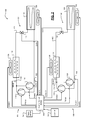
- the cooling system 100 includes an upstream cooling stage 102 with an upstream (or first) cooling circuit 104 and a downstream (or second) cooling stage 106 with a downstream cooling circuit 108.
- the cooling circuits are controlled via a cooling control module 109.
- the upstream cooling circuit 104 includes a first evaporator 110, a first expansion valve 112, a first condenser 114, a first compressor 116, and a second compressor 118.
- the downstream cooling circuit 108 includes a second evaporator 120, a second expansion valve 122, a second condenser 124, a third compressor 126, and a fourth compressor 128.
- the evaporators 110, 120 may have respective evaporator fans 130, 132. Although multiple evaporators and respective evaporator fans are shown, one or more evaporators and one or more evaporator fans may be included. One or more evaporator fans may be shared by one or more evaporators.
- the condensers 114, 124 have respective condenser fans 134, 136.
- the cooling control module 109 may generate condenser fan signals COND1. COND2, evaporator fan signals EVAP1, EVAP2, expansion valve signals EXP1, EXP2, and compressor signals PWM1, PWM2, PWM3, PWM4 to control the fans 130, 132, 134, 136, expansion valves 112, 122, and the compressors 116, 118, 126, 128.
- the cooling control module 109 may control the fans 130, 132, 134, 136, the expansion valves 112, 122, and/or the compressors 116, 118, 126, 128 based on signals from various sensors.
- the sensors may include, for example, an ambient temperature sensor 150, suction pressure sensors 152, 154, and/or head pressure sensors 156, 158.
- the ambient temperature sensor 150 may be an outdoor ambient temperature sensor and generate an ambient temperature signal T A .
- the pressure sensors 152, 154 generate suction pressure signals SUC1, SUC2 and detect pressures of fluid received by the compressors 116, 118, 126, 128.
- the evaporators 110, 120 may include, for example, micro-channel (MC) cooling coil assemblies, a MC heat exchanger, fin-and-tube cooling coil assemblies, and/or other evaporator components and assemblies.
- the expansion valves 112, 122 may be EEVs and/or thermostatic expansion valves.
- Each of the condensers 114, 124 may be of a variety of types, such as an air-cooled condenser, a water-cooled condenser, or glycol cooled condenser.
- the condensers 114, 124 may include heat rejection devices that transfer heat from return fluids to a cooler medium, such as outside air.
- the heat rejection devices may include air or liquid cooled heat exchangers.
- Each of the cooling circuits 104, 108 may include a tandem set of compressors (e.g., compressors 116, 118 or compressors 126, 128). Although the tandem set of compressors is shown as including two compressors, the tandem set of compressors may include two or more compressors. Each of the tandem compressors may be a fixed capacity scroll compressor (e.g., compressors 116, 126) or a variable capacity scroll compressor (e.g., compressors 118, 128). The variable capacity scroll compressors may be controlled via a respective digital signal received from the cooling control module 109.
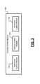
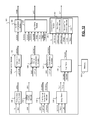
- the cooling control module 109 includes an operations control module 160, a startup control module 162, and a shutdown control module 164.
- the operations control module 160 generally controls operation of the cooling circuits 104, 108 during operation of the compressors 116, 118, 126, 128.
- the startup control module 162 generally controls operation of the cooling circuits 104, 108 during startup of the compressors 116, 118, 126, 128.
- the shutdown control module 164 generally controls operation of the cooling circuits 104, 108 during shutdown of the compressors 116, 118, 126, 128.
- the operations control module 160 performs a steady-state pressure difference (SSPD) method to control pressure differences across the compressors 116, 118, 126, 128. If a pressure difference is less than a predetermined pressure (i.e. a low-pressure difference), the operations control module 160 via the SSPD method adjusts control parameters to ensure that an appropriate level of pressure difference is maintained. The control parameters may be incrementally adjusted.
- SSPD steady-state pressure difference
- the SSPD method includes two distinct control methods; a head (high) pressure management method (referred to as SSPD-HP) illustrated in FIGs. 5A-5B , and suction (low) pressure management method (referred to as SSPD-LP) illustrated in FIGs. 7A-7B .
- Both the SSPD-HP and SSPD-LP methods may leverage functionality of related pre-existing control methods focusing solely on a head pressure and/or a suction pressure.
- Separate SSPD-HP methods may be executed for each of the cooling circuits 104, 108.
- Separate SSPD-LP methods may be executed for each of the cooling circuits 104, 108.
- two SSPD-HP methods and two SSPD-LP methods may be executed in parallel. In other words, each of the SSPD-HP, SSPD-LP methods are executed while each of the other SSPD-HP, SSPD-LP methods are executed.
- the SSPD-HP method is eligible for use by a cooling circuit having an air-cooled condenser (e.g., one of the condensers 114, 124) with variable speed fans (e.g., the condenser fans 134, 136), where the fans are controllable via a control module (e.g., the operations control module 160).
- the SSPD-LP method is eligible for use by a cooling circuit having a digital pulse width modulated (PWM) compressor (e.g., one of the compressors 116, 118, 126, 128) and/or a variable speed evaporator fans (e.g., the evaporator fans 130, 132).
- PWM digital pulse width modulated
- the head pressure management method may begin at 200.
- the following tasks 202-224 are part of a first portion of a SSPD-HP method.
- Subsequent tasks 226-234 are part of a second portion of the SSPD-HP method.
- the first parameter module 170 determines various parameters including a high-pressure (HP)-X series of parameters and a high-pressure pressure difference (HPPD)-X series of parameters.
- HP-X series of parameters include a pressure set point value HP-A and an absolute minimum pressure value HP-B.
- An absolute pressure is equal to a measured pressure plus the atomic pressure or 14.7 pounds per square inch (PSI).
- PSI pounds per square inch
- the units-of-measure for an absolute pressure is pounds per square inch (PSIA).
- the HPPD-X series of parameters includes a minimum differential pressure value HPPD-A, a hysteresis value HPPD-B, an adjustment step value HPPD-C, an adjustment time value HPPD-D, a maximum set point value HPPD-E, and a maximum absolute pressure value HPPD-F.
- the values HP-A, HP-B may be stored in a memory 186 and accessed by the operations control module 160. These values may have original versions (denoted with a subscript O) and/or updated versions (denoted with a subscript U).
- the pressure set point value HP-A is a head pressure value maintained using a proportional integral derivative (PID) method to control a condenser fan (e.g., one of the fans 134, 136).
- PID proportional integral derivative
- the PID method may be implemented via the condenser module 184, which generates a condenser signal COND to control the speed of the condenser fan.
- a PID method may use PID coefficients or gain values in a feedback algorithm to provide an output (e.g., the condenser signal COND).
- the absolute minimum pressure value HP-B refers to a minimum head pressure below which the operations control module 160 reduces speeds of the condenser fans to a minimum speed to prevent further reductions in head pressure.
- the minimum differential value HPPD-A is a minimum amount of pressure difference, which is maintained.
- the parameter HPPD-A may be associated with undirected compressor unloading. Compressor unloading may occur at pressure differences less than the parameter HPPD-A and/or at pressure differences less than a result of the parameter HPPD-A minus a predetermined safety margin.
- the hysteresis value HPPD-B is an amount of pressure above the minimum differential value HPPD-A, which is attained to begin incrementally reversing increases made during the SSPD-HP method.
- the adjustment step value HPPD-C is an amount of incremental adjustment, which is applied to the parameters HP-A and HP-B when the SSPD-HP method is active.
- the adjustment time value HPPD-D is an amount of time, which is permitted to lapse before the adjustment step value HPPD-C is adjusted.
- the maximum set point value HPPD-E is a highest allowable value, which the pressure set point value HP-A can be set to using the SSPD-HP method.
- the maximum absolute pressure value HPPD-F is a highest allowable value, which the absolute minimum pressure value HP-B can be set to using the SPPD-HP method.
- the compressor pressure module 172 determines the suction pressure and the head pressure.
- the compressor pressure module 172 may receive a suction pressure signal SUC and a head pressure signal HEAD.
- the compressor pressure module 172 determines a pressure difference based on the pressure signals SUC, HEAD to generate a pressure difference signal DIFF.
- the pressure difference signal DIFF maybe calculated by subtracting the suction pressure signal SUC from the head pressure signal HEAD.
- the high-pressure comparison module 176 compares the pressure difference signal DIFF to the minimum differential value HPPD-A and generates a first high-pressure comparison signal HCOM1. If the pressure difference signal DIFF is less than the minimum differential value HPPD-A, then task 210 is performed, otherwise task 209 may be performed.
- the first counter module 174 resets or increments a first counter value to generate a first count signal CNT1 based on the first high-pressure comparison signal HCOM1.
- the first counter value may be reset when a first iteration of tasks 208-212 is performed and incremented for subsequent iterations.
- the parameter increase module 178 determines whether the first count signal CNT1 is greater than the adjustment time value HPPD-D. If the first count signal CNT1 is greater than the adjustment time value HPPD-D, then task 214 is performed, otherwise task 204 may be performed.
- the high-pressure comparison module 176 determines whether the pressure difference signal DIFF is greater than a sum of the values HPPD-A, HPPD-B and generates a second high-pressure comparison signal HCOM2. If the pressure difference signal DIFF is not greater than the sum, then task 211 is performed, otherwise task 226 is performed. At 211, the first counter value is reset. Task 204 is performed subsequent to task 211.
- the high-pressure comparison module 176 compares the pressure set point value HP-A to the maximum set point value HPPD-E and generates a third high-pressure comparison signal HCOM3.
- Task 216 is performed when the pressure set point value HP-A is greater than or equal to maximum set point value HPPD-E, otherwise task 218 is performed.
- the parameter increase module 178 or other module of the operations control module 160 sets the pressure set point value HP-A equal to the maximum set point value HPPD-E.
- the parameter increase module 178 increases the value HP-A.
- the value HP-A may be incremented or increased by a predetermined amount (e.g., the amount indicated by the adjustment step value HPPD-C).
- the SSPD-HP method adjusts the value HP-A to alter results of a PID control method, which controls the head pressure.
- the PID control method may adjust speeds of the condenser fans 134, 136 to adjust the head pressure.
- the parameters HPPD-A, HPPD-B, HPPD-C, HPPD-D, HPPD-E, HPPD-F are used.
- HPPD-A, HPPD-B, HPPD-C, HPPD-D, HPPD-E, HPPD-F may be shared for each of the cooling circuits 104, 108 and separate SSPD-HP methods may be applied independently to each of the cooling circuits 104, 108.
- the high-pressure comparison module 176 compares the absolute minimum pressure value HP-B to the maximum absolute pressure value HPPD-F and generates a fourth high-pressure comparison signal HCOM4. If the absolute minimum pressure value HP-B is greater than or equal to the maximum absolute pressure value HPPD-F, then task 222 is performed, otherwise task 224 is performed.
- the parameter increase module 178 or other module of the operations control module 160 sets the absolute minimum pressure value HP-B equal to the maximum absolute pressure value HPPD-F.
- the parameter increase module 178 increases or increments the absolute minimum pressure value HP-B.
- the absolute minimum pressure value HP-B may be incremented or increased by a predetermined amount (e.g., the amount indicated by the adjustment step value HPPD-C).
- the SSPD-HP method adjusts the value HP-B to alter results of a PID control method, which controls the head pressure.
- the PID control method may adjust speeds of the condenser fans 134, 136 to adjust the head pressure.
- the parameters HPPD-A, HPPD-B, HPPD-C, HPPD-D, HPPD-E, HPPD-F are used.
- HPPD-A, HPPD-B, HPPD-C, HPPD-D, HPPD-E, HPPD-F may be shared for each of the cooling circuits 104, 108 and separate SSPD-HP methods may be applied independently to each of the cooling circuits 104, 108.
- the first counter value or the first count signal CNT1 is reset or incremented based on the first high-pressure comparison signal HCOM1.
- the parameter decrease module 180 determines whether the first count signal CNT1 is greater than the adjustment time value HPPD-D. Task 230 is performed when the first count signal CNT1 is greater than the adjustment time value HPPD-D, otherwise task 204 is peformed.
- the parameter decrease module 180 may determine whether the values HP-A, HP-B (or updated values HP-A U , HP-B U ) are less than or equal to their original values HP-A O , HP-B O based on the first high-pressure comparison signal HCOM1. If the values HP-A, HP-B are less than or equal to their original values, then task 232 is performed, otherwise task 234 is performed.
- the parameter decrease module 180 or other module of the operations control module 160 sets the values HP-A, HP-B to their original values HP-A O , HP-B O .
- the parameter decrease module 180 decreases or decrements the values HP-A, HP-B based on the second high-pressure comparison signal HCOM2.
- the parameter decrease module 180 may decrease each of the values HP-A, HP-B by a predetermined amount (e.g., the amount indicated by the adjustment step value HPPD-C).
- Task 204 may be performed subsequent to tasks 232 and 234.
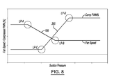
- FIG. 8 an evaporator fan speed and compressor duty cycle plot associated with the HSPM method is shown.
- the plot of FIG. 8 illustrates how adjustments in the LP-X series of parameters alters the speed of the evaporator fan and the variable compressor PWM% to reduce the suction pressure signal SUC and/or prevent the suction pressure signal SUC from exceeding a predetermined threshold.
- the second counter module 192 resets or increments a second counter value to generate a second count signal CNT2 based on the first low-pressure comparison signal LCOM1.
- the second counter value may be reset when a first iteration of tasks 258-262 is performed and incremented for subsequent iterations.
- the low-pressure comparison module 194 determines whether the pressure difference signal DIFF is greater than a sum of the values LPPD-A, LPPD-B and generates a second low-pressure comparison signal LCOM2. If the pressure difference signal DIFF is not greater than the sum, then task 270 is performed, otherwise task 261 is performed. At 261, the second counter value is reset. Task 254 is performed subsequent to task 261.
- the parameter decrease module 180 determines whether the second count signal CNT2 is greater than the adjustment time value LPPD-D. If the second count signal CNT2 is greater than the adjustment time value LPPD-D, then task 264 is performed, otherwise task 254 may be performed.
- the low-pressure comparison module 194 compares the pressure set point value LP-A to the minimum set point value LPPD-E and generates a third low-pressure comparison signal LCOM3.
- Task 254 is performed when the pressure set point value HP-A is less than or equal to minimum set point value LPPD-E, otherwise task 266 is performed.
- the low-pressure comparison module 194 compares the compressor increase value LP-C to the minimum absolute pressure value LPPD-E. If the compressor increase value LP-C is less than or equal to the minimum absolute pressure value LPPD-E, then task 254 is performed, otherwise task 268 is performed.
- the parameter decrease module 180 decreases the values LP-A, LP-B, LP-C, LP-D.
- the values LP-A, LP-B, LP-C, LP-D may be decremented or decreased by a predetermined amount (e.g., the amount indicated by the adjustment step value LPPD-C).
- the second counter module 192 resets or increments the second count signal CNT2.
- the parameter decrease module 180 determines whether the second count signal CNT2 is greater than the adjustment time value LPPD-D. Task 274 is performed when the second count signal CNT2 is greater than the adjustment time value LPPD-D, otherwise task 254 is performed.
- the parameter decrease module 180 may determine whether the values LP-A, LP-B, LP-C, LP-D (or updated values LP-A U , LP-B U , LP-C U , LP-D U ) are greater than or equal to their original values LP-A O , LP-B O , LP-C O , LP-D O based on the first low-pressure comparison signal LCOM1. If the values LP-A, LP-B, LP-C, LP-D are greater than or equal to their original values, task 276 is performed, otherwise task 278 may be performed.
- the parameter increase module 178 set the values LP-A, LP-B, LP-C, LP-D to their original values LP-A O , LP-B O , LP-C O , LP-D O .
- the low-pressure comparison module 194 determines whether the pressure difference signal DIFF is greater than a sum of the values LPPD-A and LPPD-B. Task 314 is performed when the pressure difference signal DIFF is greater than the sum of the values LPPD-A and LPPD-B, otherwise task 316 is performed.
- the other one of the methods may be enabled (or active) without dependence on the disabled method.
- the methods of FIGs. 5A , 5B , 7A , 7B , and 11 may be used to monitor and regulate compressor pressure difference(s) for an air conditioning system with tandem digital scroll compressor(s), condenser(s), and EEVs.
- the methods of FIGs. 5A , 5B , 7A , 7B , and 11 may be used to monitor and regulate compressor pressure difference(s) for an air conditioning system with fixed, digital, or tandem scroll compressor(s), a water-cooled condenser(s), and EEVs or thermostatic expansion valve(s).
- the methods of FIGs. 5A , 5B , 7A , 7B , and 11 prevent undirected unloading of compressors. As the methods are performed via the cooling control module 109, the cooling system 100 and methods can be monitored, configured, enabled, and/or disabled via a user interface 329.
- the user interface 329 may include a keypad, a keyboard, a mouse, a touch screen, or other suitable user interface.
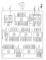
- the startup control module 162 includes a temperature error module 330, a startup cooling module 332, a first startup comparison module 334, a delay timer 336, a temperature module 338, a second startup comparison module 340, a third startup comparison module 342, a lead compressor module 344, a lag compressor module 345, and a lag timer 349.
- the parameters used and/or generated by the modules of the startup control module 162 may be stored in the memory 186. Operation of these modules is described with respect to the method of FIG. 13 .
- the lead compressor is the compressor, which starts first.
- the lag compressor has an activation point which is higher than the activation point of the lead compressor.
- startup of the lag compressor generally occurs after the startup of the lead compressor.
- the lead compressor may start before the lag compressor, for example, when the SUPD-LC method is inactive.
- a digital variable capacity scroll compressor may be the lead compressor and a fixed capacity scroll compressor may be the lag compressor. Both of the lead and lag compressors are started when cooling for a current operating condition can be satisfied by a cooling capacity of one of the lead and lag compressors.
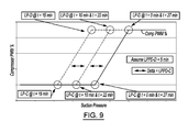
- the SUPD-LC method includes activating the lag compressor after the lead compressor, when a low-pressure difference across a compressor is detected. This allows the tandem set to operate at a full rate of volumetric displacement to more rapidly increase the pressure difference.
- the following parameters LCPD-A, LCPD-B, LCPD-C, LCPD-D, LCPD-E, LCPD-F, LCPD-X are used during the SUPD-LC method.
- the parameter LCPD-A is an outdoor ambient temperature associated with activating the lag compressor.
- the SUPD-LC method is started when the LCPD-A temperature is reached.
- the parameter LCPD-B refers to a lead compressor activation point.
- the parameter LCPD-C refers to a lead compressor deactivation point.
- the lead compressor is deactivated.
- the parameter LCPD-D refers to a lag compressor activation point.
- the lag compressor is activated.
- the parameter LCPD-E refers to a lag compressor deactivation point. When the call for cooling value CFC is less than the parameter LCPD-E, the lag compressor is deactivated.
- the startup cooling module 332 determines the call for cooling value CFC based on or as a function of the control temperature error value CFE.
- the first startup comparison module 334 compares the call for cooling value CFC with the parameter LCPD-B to generate a first CFC comparison signal SCOM1 B . If the call for cooling value CFC is greater than the parameter LCPD-B, then task 358 is performed, otherwise task 352 is performed.
- the temperature module 338 determined the outdoor ambient temperature T A and/or the second startup comparison module 340 determines the suction pressure, which may be based on the suction pressure signal SUC.
- the temperature module 338 compares the outdoor ambient temperature T A with the parameter LCPD-A to generate a second comparison signal SCOM2.
- the second startup comparison module 340 may alternatively or in addition compare the suction pressure signal SUC with the parameter LCPD-X to generate a third comparison signal SCOM3.
- task 366 is performed, otherwise task 368 is performed.
- the SUPD-LC method can be activated based on the suction pressure signal SUC.
- the activation may occur when the suction pressure signal SUC is less than the parameter LCPD-X and when the lead compressor is activated.
- the lag compressor module 345 starts the SUPD-LC method based on the second and third comparison signals SCOM2, SCOM3.
- Task 370 is performed subsequent to task 366.
- the lag compressor module 345 determines whether an alarm signal ALARM has been generated for the lag compressor.
- the alarm signal ALARM may be generated, for example, when there is fault associated with the operation of the lag compressor.
- Task 375 is performed when the result of task 372 is TRUE, otherwise task 374 is performed.
- the lag compressor module 345 determines whether the lead compressor has been turned OFF based on the PWM signal.
- Task 375 is performed when the lead compressor has been turned off, otherwise task 376 is performed.
- the lag compressor module 345 turns off the lag compressor.
- the lead compressor may also be turned off, if the lead compressor is not already turned off.
- the lag compressor module 345 determines whether the lag time signal TIMLAG is greater than the parameter LCPD-F. If the result of task 376 is TRUE, task 368 is performed, otherwise task 372 is performed.
- the startup control module 162 may further include a condenser fan module 346.
- the condenser fan module 346 may include a first fan control module 347 and a second fan control module 348.
- the condenser fan module 346 may execute a first startup pressure difference method when non-tandem compressors are used and a second startup pressure difference method when tandem compressors are used. The methods may be executed based on the outdoor ambient temperature T A , a parameter CFPD-A, parameters CFPD-TX, parameters CFPD-CAX, and parameters CFPD-CBX.
- the parameter CFPD-A refers to a SUPD-CF active time and defines an amount of time in which the SUPD-CF method is to be active after the compressor or tandem set is started.
- the parameters CFPD-TX refers to parameters CFPD-T1 through CFPD-T8, which are outdoor air temperatures associated with condenser fan speeds indicated by the parameters CFPD-CAX and CFPD-CBX.
- the parameters CFPD-CAX refers to parameters CFPD-CA1 through CFPD-CA8, which are condenser fan speeds.
- the condenser fan speeds may be used at each of the corresponding CFPD-TX temperatures when non-tandem compressors are used.
- the parameters CFPD-CAX may also be used for a lead compressor in a tandem set.
- the parameters CFPD-CBX refer to parameters CFPD-CB1 through CFPD-CB8, which are condenser fan speeds.
- the condenser fan speeds may be used at each of the corresponding CFPD-TX temperatures when the lag compressor in a tandem set is started before the timer associated with the parameter CFPD-A lapses.
- the parameters CFPD-CBX may be used with tandem scroll compressors. For air conditioning systems with multiple cooling circuits, separate sets of parameters CFPD-CAX and CFPD-CBX are provided for each individual cooling circuit.
- Table 1 provides an example of parameters CFPD-TX, CFPD-CAX, and CFPD-CBX stored in tabular form.
- Table 1 SUPD-CF Temperature and Fan Speed Parameters CFPD-T8 (Highest Temperature) CFPD-CA8 CFPD-CB8 CFPD-T7 CFPD-CA7 CFPD-CB7 CFPD-T6 CFPD-CA6 CFPD-CB6 CFPD-T5 CFPD-CA5 CFPD-CB5 CFPD-T4 CFPD-CA4 CFPD-CB4 CFPD-T3 CFPD-CA3 CFPD-CB3 CFPD-T2 CFPD-CA2 CFPD-CB2 CFPD-T1 (Lowest Temperature) CFPD-CA1 CFPD-CB1 (Lowest Temperature) CFPD-CA1 CFPD-CB1 (Lowest Temperature) CFPD-CA1 CFPD-C
- a condenser fan based startup pressure difference method for use with each set of non-tandem compressors is shown. The method may begin at 400.
- the first fan control module 347 controls speeds of the condenser fans according to a condenser fan proportional integral derivative (CFPID) method.
- the CFPID method is performed to maintain a desired head pressure.
- the CFPID method is used to generate a condenser fan control signal CF, which controls the speeds of the condenser fans.
- the condenser fan module 346 determines whether a compressor (e.g., the lead compressor and/or the lag compressor) has started based on the lead compressor signal PWM and the lag compressor signal LAG.
- the condenser fan module 346 or the second fan control module 348 starts the SUPD-CF method and temporarily overrides the CFPID method when one of the compressors has started. By doing this, the condenser fans are maintained at a reduced speed (e.g., a speed slower than when the CFPID method was active).
- the reduced condenser fan speed facilitates rapid generation and increase in the head pressure, which contributes to a rapid establishment and increase in the pressure difference during compressor startup.
- the delay timer 336 starts a second timer and generates a second timer signal TIM2 based on the first comparison signal SCOM1, the lead compressor signal PWM, and/or the lag compressor signal LAG.
- the condenser fan module 346 and/or the second fan control module 348 maintains the speeds of the condenser fans based on the outdoor ambient temperature T A and parameters CFPD-TX and CFPD-CAX.
- the condenser fan module 346 and/or the second fan control module 348 may interpolate between CFPD-TX and CFPD-CAX points to determine condenser fan speeds based on the outdoor ambient temperature T A .
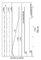
- each CFPD-CAX fan speed parameter is paired with its corresponding CFPD-TX temperature. These pairings are then used to interpolate the condenser fan speed to be used when the SUPD-CF method is active, as shown in FIG. 17.
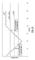
- FIG. 17 shows the condenser fan speeds that may be used for the SUPD-CF method. The condenser fan speeds may be determined by linear interpolation between the appropriate CFPD-CAX and CFPD-TX points.
- the condenser fan module 346 may determine whether the second timer signal TIM2 has exceeded a predetermined time or the time indicated by the parameter CFPD-A. Task 414 is performed when the result of task 412 is TRUE, otherwise task 410 may be performed to update the condenser fan speed and the parameters T A , CFPD-TX, CFPD-CAX.
- the condenser fan module 346 returns to controlling and/or ramping speeds of the condenser fans according to the CFPID method.
- the SUPD-CF method is deactivated.
- the second fan control module 348 relinquishes control of the condenser fans to the first fan control module 347. The method may end after task 414 at 416.
- FIG. 16 a condenser fan based startup pressure difference method for use with each set of tandem compressors is shown. The method may begin at 450.
- the delay timer 336 starts the second timer and generates the second timer signal TIM2.
- the condenser fan module 346 and/or the second fan control module 348 maintains the speeds of the condenser fans based on the outdoor ambient temperature T A and parameters CFPD-TX and CFPD-CAX.
- the condenser fan module 346 and/or the second fan control module 348 may interpolate between CFPD-TX and CFPD-CAX points to determine condenser fan speeds based on the outdoor ambient temperature T A .
- the condenser fan module 346 may determine whether the second timer signal TIM2 has exceeded a predetermined time or the time indicated by the parameter CFPD-A.
- Task 464 is performed when the result of task 462 is FALSE.
- Task 468 is performed when the result of task 462 is TRUE.
- the second fan control module 348 determines whether the lag compressor has started based on the lag compressor signal LAG. If the lag compressor has started task 466 is performed, otherwise task 460 may be performed to update the condenser fan speed and the parameters T A , CFPD-TX, CFPD-CAX.
- the condenser fan module 346 and/or the second fan control module 348 maintains the speeds of the condenser fans based on the outdoor ambient temperature T A and parameters CFPD-TX and CFPD-CBX.
- the condenser fan module 346 and/or the second fan control module 348 may interpolate between CFPD-TX and CFPD-CBX points to determine condenser fan speeds based on the outdoor ambient temperature T A .
- each CFPD-CBX fan speed parameter is paired with its corresponding CFPD-TX temperature. These pairings are then used to interpolate the condenser fan speeds.
- the condenser fan speeds may be determined by linear interpolation between the appropriate CFPD-CBX and CFPD-TX points.
- the condenser fan module 346 returns to controlling and/or ramping speeds of the condenser fans according to the CFPID method.
- the SUPD-CF method is deactivated.
- the second fan control module 348 relinquishes control of the condenser fans to the first fan control module 347.
- the method may end after task 468 at 470.
- the parameters of the methods of FIGs. 13 , 15, and 16 are configurable via the user interface 329 of FIG. 2 .
- the methods manipulate compressor and condenser fan operation based on an outdoor ambient temperature. This control proactively prevents low-compressor pressure differences during compressor startup and minimizes undirected compressor unloading associated with operating a tandem set of compressors in an unloaded condition during compressor startup.
- the shutdown control module 164 may include the lag compressor module 345, a load duration timer 484, an overwrite timer 485, a routine module 486, a lead compressor module 487, an expansion valve module 488, a shutdown parameter module 489, and a condenser fan module 346.
- the parameters used and/or generated by the modules of the shutdown control module 164 may be stored in the memory 186. The operations of the modules are described with respect to the method of FIG. 20 .
- the lead compressor may start before the lag compressor when the call for cooling value CFC increases above a corresponding first activation point.
- the lag compressor has a second activation point, which is higher than the first activation point.
- startup of the lag compressor occurs after startup of the lead compressor.
- the lead compressor may be a digital scroll compressor and the lag compressor may be a fixed scroll compressor.
- the CTPD method may begin at 500.
- the expansion valve module 488 starts a motor overload protection (MOP) method to protect compressor motors via an overload module. This effectively reduces an opening percentage of the EEV when the lag compressor in the tandem set turns OFF.
- MOP motor overload protection
- the expansion valve module 488 includes an overload module 491, an evaporator temperature module 492, an overwrite module 493, and an opening module 494.
- the MOP method may include use of a parameter MOP-A, which refers to a temperature threshold.
- the temperature threshold is a temperature above which the MOP method is initiated by the overload module 491.
- the MOP method is initiated if a saturated suction temperature T SUC is greater than the temperature threshold as calculated by the overload module.
- the parameter EVPD-A refers to a MOP temperature and defines a value above which the MOP-A temperature is set.
- the MOP-A temperature is set equal to the parameter EVPD-A when the CTPD-EV method is active.
- the parameter EVPD-B refers to a CTPD-EV duration, which defines an amount of time that the parameter MOP-A is to be overwritten or replaced with the parameter EVPD-A.
- the parameter EVPD-C refers to a MOP temperature restore rate which defines a rate at which the MOP-A temperature is restored to an original value (the MOP-A is no longer overridden) once the CTPD-EV method becomes inactive.
- FIG. 21 a digital scroll plot for the CTPD-DS method is shown.
- FIG. 21 includes a digital scroll PWM% signal, a PWMCFC signal, and a lag compressor status signal.
- the digital scroll PWM% signal starts at the PWMCFC signal, increases to a peak (e.g., 100%) when the CTPD-DS method is activated, and then decreases back to the PWMCFC signal when the load duration time has lapsed.
- the PWMCFC signal transitions from a low state to a high state when the lag compressor motor is deactivated.
- the overwrite module 493 changes the parameter MOP-A stored in the first location back from the parameter EVPD-A to the original parameter MOP-A stored at the second location. This is done at the rate defined by parameter EVPD-C.
- the original parameter MOP-A is copied from the second location of the memory 186 to the first location of the memory 186.
- the CTPD-EV method may end at 532 when the parameter MOP-A has been completely restored to its original value.
- FIG. 22 an expansion valve plot for the CTPD-EV method is shown.
- FIG. 22 includes an EVPID signal, an EEV opening% signal, and a MOP-A signal, which are associated respectively with the EVPID value, the opening percentage of the EEV, and the parameter MOP-A.
- FIG. 22 also includes the lag compressor motor status signal. As shown, the LAG compressor is switched OFF the predetermined period after the parameter MOP-A is set equal to the parameter EVPD-A. At this point, the EEV opening% signal ramps down and remains at a reduced EEV opening percentage until the overwrite timer is greater than the parameter EVPD-B. The parameter MOP-A is then ramped up to its original value and the EEV opening% signal is increased to the EVPID value.
- the condenser fan module 346 may control the speeds of the condenser fan using a condenser fan proportional integral derivative (CFPID) method.
- the speeds of the condenser fan may be controlled to maintain a predetermined head pressure.
- the CFPID method may be used to generate a condenser output signal CF to control the condenser fan.
- the CFPID method may be used to generate the condenser output signal CF based on a parameter CF-A.
- the parameter CF-A refers to a condenser maximum fan speed, which defines a maximum speed that the condenser fan can operate.
- the parameter CF-A may be used as a high-limit for the actual speed of the condenser fan.
- the parameter CF-A may be set equal to a predetermined percentage (e.g., 90%).
- the condenser fan may operate at the predetermined percentage until the parameter CFPID is less than the condenser output signal CF-A.
- the CTPD-FR method is used to temporarily reduce the parameter CF-A to provide a reduction in the speed of the condenser fan. This causes the head pressure HEAD in the corresponding cooling circuit to increase. By operating the tandem set at an elevated head pressure before the lag compressor turns OFF, loss in the pressure difference can be avoided.
- the CTPD-FR method may include use of a parameter FRPD-A.
- the parameter FRPD-A refers to a condenser fan reduction exponent.
- the parameter FRPD-A is a value that is used to determine a reduction magnitude in a speed of the condenser fan relative to a change in digital scroll PWM%.
- Equation 1 provides a relationship between a maximum allowable condenser fan speed F 1 before the lag compressor is turned OFF and a maximum allowable condenser fan speed F 2 after the lag compressor is turned OFF.
- F 2 F 1 C 2 C 1 A
- the variable A is equal to the parameter FRPD-A.
- the parameter CF-A may be adjusted based on the variables F 1 (original CF-A) and F 2 (modified CF-A when CTPD-FR is started).
- the variable C 1 is equal to the parameter PWMCFC before lag compressor is turned OFF.
- the variable C 2 is equal to the parameter PWMCFC after the lag compressor is turned OFF.
- the variable C 2 is calculated by using the call for cooling value CFC at the time the CTPD-FR method is started. Based on Equation 1, increasing the FRPD-A parameter increases an amount of potential reduction in the speed of the condenser fan during the CTPD-FR method.
- the condenser fan module 346 may evaluate Equation 1.
- the parameter CF-A or original CF-A value is copied from a first location of the memory 186 to a second location of the memory 186.
- the parameter CF-A is then set equal to the maximum allowable condenser fan speed F 2 by storing F 2 at the first location of the memory 186. This causes the condenser fan module 346 to reduce the speed of the condenser fan to a value equal to the maximum allowable condenser fan speed F 2 .
- the speed of the condenser fan may be controlled based on the original CF-A value or the maximum allowable condenser fan speed F 1 prior to the task 528 and/or prior to the lag compressor being shut OFF.
- the changeover to the maximum allowable condenser fan speed F 2 may include a step reduction in the speed of the condenser fan when the lag compressor turns OFF, as F 2 may be less than F 1 .
- condenser fan module 346 restores the parameter CF-A back to its original value.
- the condenser fan is operated based on the CFPID value to ramp the speed of the condenser fan towards the original CF-A value and back to a speed prior to the lag compressor being turned OFF. This is done at a rate based on proportional (P), integral (I), derivative (D) coefficients associated with the CFPID method.
- the CTPD method and/or CTPD-FR method may end at 532.
- FIG. 23 a condenser fan speed plot for the CTPD-FR method is shown.
- FIG. 23 includes a CF-A signal and a CFPID signal, which correspond respectively to the parameter CF-A and the CFPID value.
- FIG. 23 also includes the condenser fan speed signal CF and the lag compressor motor status signal.
- the condenser fan speed signal CF is reduced when the parameter CF-A is reduced at task 528. This may occur at a predetermined period (e.g., 10 seconds) before the lag compressor is turned OFF.
- the parameter CF-A is increased back to its original value after the lag compressor is turned OFF.
- the condenser fan speed signal CF is ramped up when the parameter CF-A is increased, which occurs at task 530.
- the method of FIG. 20 manipulates operation of system components in anticipation of one of the compressors in the tandem set being turned OFF.
- the method includes tasks to prevent occurance of a low-pressure difference during lag compressor shutdown. This prevents damage to compressors and helps diminish undue reductions in cooling capacity when the lag compressor in the tandem set of compressors is turned OFF.
- the parameters for the method of FIG. 20 may be configurable via the user interface 329 of FIG. 2 . This allows the method to be configurable.
- the method interrupts operational control of a digital scroll compressor PWM%, an EEV opening position, and speeds of condenser fans when conditions to turn OFF one of the compressors in the tandem set are satisfied. This proactively reduces the chances of running the tandem set at low-pressure difference associated with an unloaded compressor condition.
- module may refer to, be part of, or include an Application Specific Integrated Circuit (ASIC); an electronic circuit; a combinational logic circuit; a field programmable gate array (FPGA); a processor (shared, dedicated, or group) that executes code; other suitable hardware components that provide the described functionality; or a combination of some or all of the above, such as in a system-on-chip.
- ASIC Application Specific Integrated Circuit
- FPGA field programmable gate array
- the term module may include memory (shared, dedicated, or group) that stores code executed by the processor.
- code may include software, firmware, and/or microcode, and may refer to programs, methods, functions, classes, and/or objects.
- shared means that some or all code from multiple modules may be executed using a single (shared) processor. In addition, some or all code from multiple modules may be stored by a single (shared) memory.
- group means that some or all code from a single module may be executed using a group of processors. In addition, some or all code from a single module may be stored using a group of memories.
- the apparatuses and methods described herein may be implemented by one or more computer programs executed by one or more processors.
- the computer programs include processor-executable instructions that are stored on a non-transitory tangible computer readable medium.
- the computer programs may also include stored data.
- Non-limiting examples of the non-transitory tangible computer readable medium are nonvolatile memory, magnetic storage, and optical storage.
- first, second, third, etc. may be used herein to describe various elements, components and/or modules, these items should not be limited by these terms. These terms may be only used to distinguish one item from another item. Terms such as “first,” “second,” and other numerical terms when used herein do not imply a sequence or order unless clearly indicated by the context. Thus, a first item discussed herein could be termed a second item without departing from the teachings of the example implementations.
Landscapes
- Engineering & Computer Science (AREA)
- Mechanical Engineering (AREA)
- General Engineering & Computer Science (AREA)
- Physics & Mathematics (AREA)
- Thermal Sciences (AREA)
- Air Conditioning Control Device (AREA)
- Control Of Motors That Do Not Use Commutators (AREA)
- Control Of Positive-Displacement Pumps (AREA)
- Control Of Positive-Displacement Air Blowers (AREA)
Applications Claiming Priority (2)
| Application Number | Priority Date | Filing Date | Title |
|---|---|---|---|
| US201361765884P | 2013-02-18 | 2013-02-18 | |
| US14/169,185 US9476624B2 (en) | 2013-02-18 | 2014-01-31 | Scroll compressor differential pressure control during compressor shutdown transitions |
Publications (3)
| Publication Number | Publication Date |
|---|---|
| EP2767784A2 true EP2767784A2 (de) | 2014-08-20 |
| EP2767784A3 EP2767784A3 (de) | 2015-11-18 |
| EP2767784B1 EP2767784B1 (de) | 2017-10-18 |
Family
ID=50112831
Family Applications (1)
| Application Number | Title | Priority Date | Filing Date |
|---|---|---|---|
| EP14155521.9A Active EP2767784B1 (de) | 2013-02-18 | 2014-02-18 | Scrollverdichter-Differenzdrucksteuerung während Kompressorabstellungsübergängen |
Country Status (3)
| Country | Link |
|---|---|
| US (1) | US9476624B2 (de) |
| EP (1) | EP2767784B1 (de) |
| CN (1) | CN103994618B (de) |
Cited By (2)
| Publication number | Priority date | Publication date | Assignee | Title |
|---|---|---|---|---|
| EP3207251A1 (de) * | 2014-10-13 | 2017-08-23 | BITZER Kühlmaschinenbau GmbH | Kältemittelverdichter |
| WO2019118220A1 (en) * | 2017-12-11 | 2019-06-20 | Vertiv Corporation | Air conditioning systems and methods with cooling capacity modulation via fixed pump operation and variable condenser fan operation |
Families Citing this family (15)
| Publication number | Priority date | Publication date | Assignee | Title |
|---|---|---|---|---|
| US8011191B2 (en) | 2009-09-30 | 2011-09-06 | Thermo Fisher Scientific (Asheville) Llc | Refrigeration system having a variable speed compressor |
| EP2792970B1 (de) * | 2011-12-09 | 2018-10-31 | Daikin Industries, Ltd. | Behälterkühlvorrichtung |
| US20140260380A1 (en) * | 2013-03-15 | 2014-09-18 | Energy Recovery Systems Inc. | Compressor control for heat transfer system |
| US20150338111A1 (en) * | 2014-05-23 | 2015-11-26 | Lennox lndustries lnc. | Variable Speed Outdoor Fan Control |
| CN104567159B (zh) * | 2014-12-26 | 2017-01-18 | 珠海格力电器股份有限公司 | 制冷机组的压差控制方法及制冷机组 |
| CN107208641B (zh) * | 2015-01-15 | 2019-05-31 | 阿特拉斯·科普柯空气动力股份有限公司 | 用于控制压缩机/真空泵速度的方法 |
| US10739045B2 (en) * | 2016-02-10 | 2020-08-11 | Johnson Controls Technology Company | Systems and methods for controlling a refrigeration system |
| US10414241B2 (en) | 2016-06-30 | 2019-09-17 | Emerson Climate Technologies, Inc. | Systems and methods for capacity modulation through eutectic plates |
| US10569620B2 (en) | 2016-06-30 | 2020-02-25 | Emerson Climate Technologies, Inc. | Startup control systems and methods to reduce flooded startup conditions |
| US10532632B2 (en) * | 2016-06-30 | 2020-01-14 | Emerson Climate Technologies, Inc. | Startup control systems and methods for high ambient conditions |
| EP3500805B1 (de) | 2016-08-22 | 2022-03-09 | Johnson Controls Technology Company | Systeme und verfahren zur steuerung eines kühlsystems |
| EP3607256B1 (de) | 2017-04-06 | 2021-11-03 | Carrier Corporation | Verfahren zur verringerung des maximalen einschaltstroms eines kompressorsystems, mehrere asynchrone elektromotoren umfassend, und kompressorsystem zur implementierung dieses verfahrens |
| CN108507246A (zh) * | 2018-03-30 | 2018-09-07 | 北京新能源汽车股份有限公司 | 热泵空调系统的控制方法、装置及电子设备 |
| CN117662445B (zh) * | 2024-01-30 | 2024-04-09 | 玉得气体有限责任公司 | 一种氮压机运行控制方法及系统 |
| CN119509092B (zh) * | 2024-12-23 | 2026-02-06 | 珠海格力节能环保制冷技术研究中心有限公司 | 压缩机过载保护的控制方法、装置和空调器 |
Family Cites Families (15)
| Publication number | Priority date | Publication date | Assignee | Title |
|---|---|---|---|---|
| SE406001B (sv) * | 1972-10-23 | 1979-01-15 | Ifield Richard J | Kolvpump med variabel slagvolym |
| US4152902A (en) * | 1976-01-26 | 1979-05-08 | Lush Lawrence E | Control for refrigeration compressors |
| US6047557A (en) * | 1995-06-07 | 2000-04-11 | Copeland Corporation | Adaptive control for a refrigeration system using pulse width modulated duty cycle scroll compressor |
| US6170277B1 (en) | 1999-01-19 | 2001-01-09 | Carrier Corporation | Control algorithm for maintenance of discharge pressure |
| US6999996B2 (en) | 2000-03-14 | 2006-02-14 | Hussmann Corporation | Communication network and method of communicating data on the same |
| US6532751B1 (en) * | 2002-03-22 | 2003-03-18 | Whirlpool Corporation | Method of maximizing ice production in a refrigeration appliance |
| US6826917B1 (en) | 2003-08-01 | 2004-12-07 | York International Corporation | Initial pull down control for a multiple compressor refrigeration system |
| JP2006257882A (ja) | 2005-03-15 | 2006-09-28 | Hitachi Home & Life Solutions Inc | スクロール圧縮機 |
| US9568206B2 (en) | 2006-08-15 | 2017-02-14 | Schneider Electric It Corporation | Method and apparatus for cooling |
| DK2122274T3 (da) | 2007-02-15 | 2017-11-27 | Carrier Corp | Pulsbreddemodulation med reduceret sugetryk til at forbedre effektivitet |
| JP5162158B2 (ja) | 2007-05-31 | 2013-03-13 | 株式会社日立産機システム | スクロール式増圧装置 |
| JP5335346B2 (ja) | 2008-09-26 | 2013-11-06 | 三洋電機株式会社 | 冷却システム |
| US8192171B2 (en) * | 2009-01-15 | 2012-06-05 | Ingersoll-Rand Company | Compressor system |
| WO2010120519A2 (en) | 2009-03-31 | 2010-10-21 | Johnson Controls Technology Company | Control system for operating condenser fans |
| CN103380334B (zh) | 2011-02-22 | 2016-03-16 | 日立空调·家用电器株式会社 | 冷冻循环装置 |
-
2014
- 2014-01-31 US US14/169,185 patent/US9476624B2/en active Active
- 2014-02-18 CN CN201410055008.8A patent/CN103994618B/zh active Active
- 2014-02-18 EP EP14155521.9A patent/EP2767784B1/de active Active
Non-Patent Citations (1)
| Title |
|---|
| None |
Cited By (4)
| Publication number | Priority date | Publication date | Assignee | Title |
|---|---|---|---|---|
| EP3207251A1 (de) * | 2014-10-13 | 2017-08-23 | BITZER Kühlmaschinenbau GmbH | Kältemittelverdichter |
| EP3207251B1 (de) * | 2014-10-13 | 2025-08-20 | BITZER Kühlmaschinenbau GmbH | Kältemittelverdichter |
| WO2019118220A1 (en) * | 2017-12-11 | 2019-06-20 | Vertiv Corporation | Air conditioning systems and methods with cooling capacity modulation via fixed pump operation and variable condenser fan operation |
| US10883750B2 (en) | 2017-12-11 | 2021-01-05 | Vertiv Corporation | Air conditioning systems and methods with cooling capacity modulation via fixed pump operation and variable condenser fan operation |
Also Published As
| Publication number | Publication date |
|---|---|
| CN103994618B (zh) | 2018-11-16 |
| EP2767784B1 (de) | 2017-10-18 |
| CN103994618A (zh) | 2014-08-20 |
| EP2767784A3 (de) | 2015-11-18 |
| US9476624B2 (en) | 2016-10-25 |
| US20140230467A1 (en) | 2014-08-21 |
Similar Documents
| Publication | Publication Date | Title |
|---|---|---|
| EP2767784B1 (de) | Scrollverdichter-Differenzdrucksteuerung während Kompressorabstellungsübergängen | |
| EP2767780B1 (de) | Scrollverdichter-Differenzdrucksteuerungstechniken | |
| EP2767785B1 (de) | Scrollverdichter-Differenzdrucksteuerung der Verdichteranlaufübergänge | |
| US9746224B2 (en) | Expansion valve setpoint control systems and methods | |
| US20140137573A1 (en) | Expansion Valve Position Control Systems And Methods | |
| US8973379B2 (en) | Refrigeration control systems and methods for modular compact chiller units | |
| CN107667264B (zh) | 气候控制系统和控制可变容量压缩机的方法 | |
| CN108779928B (zh) | 用于压缩机和室内风扇的方法和气候控制系统 | |
| US10883750B2 (en) | Air conditioning systems and methods with cooling capacity modulation via fixed pump operation and variable condenser fan operation | |
| EP3199889B1 (de) | Klimaanlage | |
| WO2008143608A1 (en) | Compressor motor control | |
| EP3417218A1 (de) | Verdichterkapazitätmodulationssystem für mehrere verdichter | |
| JP2013210149A (ja) | 熱源システムの制御装置、熱源システムの制御方法、熱源システム、電力調整ネットワークシステム、及び熱源機の制御装置 | |
| WO2006046394A1 (ja) | 冷凍装置 | |
| EP3647680A1 (de) | Verfahren und vorrichtung zur steuerung eines expansionsventils | |
| KR101911272B1 (ko) | 공기조화기 및 그 제어방법 | |
| JP5931774B2 (ja) | ターボ冷凍機の最大負荷率算出装置及びその方法並びに熱源システム及びその台数制御方法 | |
| JP6076583B2 (ja) | ヒートポンプ | |
| CN107957157B (zh) | 热泵及其制热目标温度的控制方法 | |
| KR20060069714A (ko) | 공기 조화기의 압축기 토출온도 상승 억제 방법 | |
| JP4176677B2 (ja) | 空気調和機 | |
| CN114151948B (zh) | 一种变频热泵空调机组的温度恒定控制方法、设备和系统 | |
| CN116045562A (zh) | 压缩机延命运行方法及空调器 | |
| CA2716306C (en) | Outdoor fan and indoor blower controller for heating, ventilation and air conditioning system and method of operation thereof | |
| CN112384701A (zh) | 经由主动阀控制的用于压缩机操作范围扩展的方法和系统 |
Legal Events
| Date | Code | Title | Description |
|---|---|---|---|
| PUAI | Public reference made under article 153(3) epc to a published international application that has entered the european phase |
Free format text: ORIGINAL CODE: 0009012 |
|
| 17P | Request for examination filed |
Effective date: 20140218 |
|
| AK | Designated contracting states |
Kind code of ref document: A2 Designated state(s): AL AT BE BG CH CY CZ DE DK EE ES FI FR GB GR HR HU IE IS IT LI LT LU LV MC MK MT NL NO PL PT RO RS SE SI SK SM TR |
|
| AX | Request for extension of the european patent |
Extension state: BA ME |
|
| PUAL | Search report despatched |
Free format text: ORIGINAL CODE: 0009013 |
|
| AK | Designated contracting states |
Kind code of ref document: A3 Designated state(s): AL AT BE BG CH CY CZ DE DK EE ES FI FR GB GR HR HU IE IS IT LI LT LU LV MC MK MT NL NO PL PT RO RS SE SI SK SM TR |
|
| AX | Request for extension of the european patent |
Extension state: BA ME |
|
| RIC1 | Information provided on ipc code assigned before grant |
Ipc: F04C 14/02 20060101ALI20151015BHEP Ipc: F04C 18/02 20060101ALI20151015BHEP Ipc: F25B 49/02 20060101AFI20151015BHEP |
|
| R17P | Request for examination filed (corrected) |
Effective date: 20160311 |
|
| RAX | Requested extension states of the european patent have changed |
Extension state: BA Payment date: 20160311 Extension state: ME Payment date: 20160311 |
|
| RBV | Designated contracting states (corrected) |
Designated state(s): AL AT BE BG CH CY CZ DE DK EE ES FI FR GB GR HR HU IE IS IT LI LT LU LV MC MK MT NL NO PL PT RO RS SE SI SK SM TR |
|
| GRAP | Despatch of communication of intention to grant a patent |
Free format text: ORIGINAL CODE: EPIDOSNIGR1 |
|
| RIC1 | Information provided on ipc code assigned before grant |
Ipc: F04C 14/02 20060101ALI20170519BHEP Ipc: F04C 18/02 20060101ALI20170519BHEP Ipc: F25B 49/02 20060101AFI20170519BHEP |
|
| INTG | Intention to grant announced |
Effective date: 20170607 |
|
| GRAS | Grant fee paid |
Free format text: ORIGINAL CODE: EPIDOSNIGR3 |
|
| GRAA | (expected) grant |
Free format text: ORIGINAL CODE: 0009210 |
|
| AK | Designated contracting states |
Kind code of ref document: B1 Designated state(s): AL AT BE BG CH CY CZ DE DK EE ES FI FR GB GR HR HU IE IS IT LI LT LU LV MC MK MT NL NO PL PT RO RS SE SI SK SM TR |
|
| AX | Request for extension of the european patent |
Extension state: BA ME |
|
| REG | Reference to a national code |
Ref country code: GB Ref legal event code: FG4D |
|
| REG | Reference to a national code |
Ref country code: CH Ref legal event code: EP |
|
| REG | Reference to a national code |
Ref country code: AT Ref legal event code: REF Ref document number: 938326 Country of ref document: AT Kind code of ref document: T Effective date: 20171115 Ref country code: IE Ref legal event code: FG4D |
|
| REG | Reference to a national code |
Ref country code: DE Ref legal event code: R096 Ref document number: 602014015850 Country of ref document: DE |
|
| REG | Reference to a national code |
Ref country code: NL Ref legal event code: MP Effective date: 20171018 |
|
| REG | Reference to a national code |
Ref country code: FR Ref legal event code: PLFP Year of fee payment: 5 |
|
| REG | Reference to a national code |
Ref country code: LT Ref legal event code: MG4D |
|
| REG | Reference to a national code |
Ref country code: AT Ref legal event code: MK05 Ref document number: 938326 Country of ref document: AT Kind code of ref document: T Effective date: 20171018 |
|
| PG25 | Lapsed in a contracting state [announced via postgrant information from national office to epo] |
Ref country code: NL Free format text: LAPSE BECAUSE OF FAILURE TO SUBMIT A TRANSLATION OF THE DESCRIPTION OR TO PAY THE FEE WITHIN THE PRESCRIBED TIME-LIMIT Effective date: 20171018 |
|
| PG25 | Lapsed in a contracting state [announced via postgrant information from national office to epo] |
Ref country code: SE Free format text: LAPSE BECAUSE OF FAILURE TO SUBMIT A TRANSLATION OF THE DESCRIPTION OR TO PAY THE FEE WITHIN THE PRESCRIBED TIME-LIMIT Effective date: 20171018 Ref country code: FI Free format text: LAPSE BECAUSE OF FAILURE TO SUBMIT A TRANSLATION OF THE DESCRIPTION OR TO PAY THE FEE WITHIN THE PRESCRIBED TIME-LIMIT Effective date: 20171018 Ref country code: LT Free format text: LAPSE BECAUSE OF FAILURE TO SUBMIT A TRANSLATION OF THE DESCRIPTION OR TO PAY THE FEE WITHIN THE PRESCRIBED TIME-LIMIT Effective date: 20171018 Ref country code: NO Free format text: LAPSE BECAUSE OF FAILURE TO SUBMIT A TRANSLATION OF THE DESCRIPTION OR TO PAY THE FEE WITHIN THE PRESCRIBED TIME-LIMIT Effective date: 20180118 Ref country code: ES Free format text: LAPSE BECAUSE OF FAILURE TO SUBMIT A TRANSLATION OF THE DESCRIPTION OR TO PAY THE FEE WITHIN THE PRESCRIBED TIME-LIMIT Effective date: 20171018 |
|
| PG25 | Lapsed in a contracting state [announced via postgrant information from national office to epo] |
Ref country code: IS Free format text: LAPSE BECAUSE OF FAILURE TO SUBMIT A TRANSLATION OF THE DESCRIPTION OR TO PAY THE FEE WITHIN THE PRESCRIBED TIME-LIMIT Effective date: 20180218 Ref country code: AT Free format text: LAPSE BECAUSE OF FAILURE TO SUBMIT A TRANSLATION OF THE DESCRIPTION OR TO PAY THE FEE WITHIN THE PRESCRIBED TIME-LIMIT Effective date: 20171018 Ref country code: LV Free format text: LAPSE BECAUSE OF FAILURE TO SUBMIT A TRANSLATION OF THE DESCRIPTION OR TO PAY THE FEE WITHIN THE PRESCRIBED TIME-LIMIT Effective date: 20171018 Ref country code: HR Free format text: LAPSE BECAUSE OF FAILURE TO SUBMIT A TRANSLATION OF THE DESCRIPTION OR TO PAY THE FEE WITHIN THE PRESCRIBED TIME-LIMIT Effective date: 20171018 Ref country code: BG Free format text: LAPSE BECAUSE OF FAILURE TO SUBMIT A TRANSLATION OF THE DESCRIPTION OR TO PAY THE FEE WITHIN THE PRESCRIBED TIME-LIMIT Effective date: 20180118 Ref country code: RS Free format text: LAPSE BECAUSE OF FAILURE TO SUBMIT A TRANSLATION OF THE DESCRIPTION OR TO PAY THE FEE WITHIN THE PRESCRIBED TIME-LIMIT Effective date: 20171018 Ref country code: GR Free format text: LAPSE BECAUSE OF FAILURE TO SUBMIT A TRANSLATION OF THE DESCRIPTION OR TO PAY THE FEE WITHIN THE PRESCRIBED TIME-LIMIT Effective date: 20180119 |
|
| REG | Reference to a national code |
Ref country code: DE Ref legal event code: R097 Ref document number: 602014015850 Country of ref document: DE |
|
| PG25 | Lapsed in a contracting state [announced via postgrant information from national office to epo] |
Ref country code: CZ Free format text: LAPSE BECAUSE OF FAILURE TO SUBMIT A TRANSLATION OF THE DESCRIPTION OR TO PAY THE FEE WITHIN THE PRESCRIBED TIME-LIMIT Effective date: 20171018 Ref country code: SK Free format text: LAPSE BECAUSE OF FAILURE TO SUBMIT A TRANSLATION OF THE DESCRIPTION OR TO PAY THE FEE WITHIN THE PRESCRIBED TIME-LIMIT Effective date: 20171018 Ref country code: DK Free format text: LAPSE BECAUSE OF FAILURE TO SUBMIT A TRANSLATION OF THE DESCRIPTION OR TO PAY THE FEE WITHIN THE PRESCRIBED TIME-LIMIT Effective date: 20171018 Ref country code: EE Free format text: LAPSE BECAUSE OF FAILURE TO SUBMIT A TRANSLATION OF THE DESCRIPTION OR TO PAY THE FEE WITHIN THE PRESCRIBED TIME-LIMIT Effective date: 20171018 |
|
| PLBE | No opposition filed within time limit |
Free format text: ORIGINAL CODE: 0009261 |
|
| STAA | Information on the status of an ep patent application or granted ep patent |
Free format text: STATUS: NO OPPOSITION FILED WITHIN TIME LIMIT |
|
| PG25 | Lapsed in a contracting state [announced via postgrant information from national office to epo] |
Ref country code: RO Free format text: LAPSE BECAUSE OF FAILURE TO SUBMIT A TRANSLATION OF THE DESCRIPTION OR TO PAY THE FEE WITHIN THE PRESCRIBED TIME-LIMIT Effective date: 20171018 Ref country code: SM Free format text: LAPSE BECAUSE OF FAILURE TO SUBMIT A TRANSLATION OF THE DESCRIPTION OR TO PAY THE FEE WITHIN THE PRESCRIBED TIME-LIMIT Effective date: 20171018 Ref country code: PL Free format text: LAPSE BECAUSE OF FAILURE TO SUBMIT A TRANSLATION OF THE DESCRIPTION OR TO PAY THE FEE WITHIN THE PRESCRIBED TIME-LIMIT Effective date: 20171018 |
|
| REG | Reference to a national code |
Ref country code: CH Ref legal event code: PL |
|
| 26N | No opposition filed |
Effective date: 20180719 |
|
| PG25 | Lapsed in a contracting state [announced via postgrant information from national office to epo] |
Ref country code: MC Free format text: LAPSE BECAUSE OF FAILURE TO SUBMIT A TRANSLATION OF THE DESCRIPTION OR TO PAY THE FEE WITHIN THE PRESCRIBED TIME-LIMIT Effective date: 20171018 |
|
| REG | Reference to a national code |
Ref country code: IE Ref legal event code: MM4A |
|
| REG | Reference to a national code |
Ref country code: BE Ref legal event code: MM Effective date: 20180228 |
|
| PG25 | Lapsed in a contracting state [announced via postgrant information from national office to epo] |
Ref country code: LU Free format text: LAPSE BECAUSE OF NON-PAYMENT OF DUE FEES Effective date: 20180218 Ref country code: LI Free format text: LAPSE BECAUSE OF NON-PAYMENT OF DUE FEES Effective date: 20180228 Ref country code: CH Free format text: LAPSE BECAUSE OF NON-PAYMENT OF DUE FEES Effective date: 20180228 Ref country code: SI Free format text: LAPSE BECAUSE OF FAILURE TO SUBMIT A TRANSLATION OF THE DESCRIPTION OR TO PAY THE FEE WITHIN THE PRESCRIBED TIME-LIMIT Effective date: 20171018 |
|
| REG | Reference to a national code |
Ref country code: DE Ref legal event code: R081 Ref document number: 602014015850 Country of ref document: DE Owner name: VERTIV CORPORATION, COLUMBUS, US Free format text: FORMER OWNER: LIEBERT CORPORATION, COLUMBUS, OH 43085, US |
|
| PG25 | Lapsed in a contracting state [announced via postgrant information from national office to epo] |
Ref country code: IE Free format text: LAPSE BECAUSE OF NON-PAYMENT OF DUE FEES Effective date: 20180218 |
|
| PG25 | Lapsed in a contracting state [announced via postgrant information from national office to epo] |
Ref country code: BE Free format text: LAPSE BECAUSE OF NON-PAYMENT OF DUE FEES Effective date: 20180228 |
|
| PG25 | Lapsed in a contracting state [announced via postgrant information from national office to epo] |
Ref country code: MT Free format text: LAPSE BECAUSE OF NON-PAYMENT OF DUE FEES Effective date: 20180218 |
|
| PG25 | Lapsed in a contracting state [announced via postgrant information from national office to epo] |
Ref country code: TR Free format text: LAPSE BECAUSE OF FAILURE TO SUBMIT A TRANSLATION OF THE DESCRIPTION OR TO PAY THE FEE WITHIN THE PRESCRIBED TIME-LIMIT Effective date: 20171018 |
|
| PG25 | Lapsed in a contracting state [announced via postgrant information from national office to epo] |
Ref country code: HU Free format text: LAPSE BECAUSE OF FAILURE TO SUBMIT A TRANSLATION OF THE DESCRIPTION OR TO PAY THE FEE WITHIN THE PRESCRIBED TIME-LIMIT; INVALID AB INITIO Effective date: 20140218 Ref country code: PT Free format text: LAPSE BECAUSE OF FAILURE TO SUBMIT A TRANSLATION OF THE DESCRIPTION OR TO PAY THE FEE WITHIN THE PRESCRIBED TIME-LIMIT Effective date: 20171018 |
|
| PG25 | Lapsed in a contracting state [announced via postgrant information from national office to epo] |
Ref country code: MK Free format text: LAPSE BECAUSE OF NON-PAYMENT OF DUE FEES Effective date: 20171018 Ref country code: CY Free format text: LAPSE BECAUSE OF FAILURE TO SUBMIT A TRANSLATION OF THE DESCRIPTION OR TO PAY THE FEE WITHIN THE PRESCRIBED TIME-LIMIT Effective date: 20171018 |
|
| PG25 | Lapsed in a contracting state [announced via postgrant information from national office to epo] |
Ref country code: AL Free format text: LAPSE BECAUSE OF FAILURE TO SUBMIT A TRANSLATION OF THE DESCRIPTION OR TO PAY THE FEE WITHIN THE PRESCRIBED TIME-LIMIT Effective date: 20171018 |
|
| P01 | Opt-out of the competence of the unified patent court (upc) registered |
Effective date: 20230621 |
|
| PGFP | Annual fee paid to national office [announced via postgrant information from national office to epo] |
Ref country code: GB Payment date: 20260227 Year of fee payment: 13 |
|
| PGFP | Annual fee paid to national office [announced via postgrant information from national office to epo] |
Ref country code: DE Payment date: 20260227 Year of fee payment: 13 |
|
| PGFP | Annual fee paid to national office [announced via postgrant information from national office to epo] |
Ref country code: IT Payment date: 20260219 Year of fee payment: 13 |
|
| PGFP | Annual fee paid to national office [announced via postgrant information from national office to epo] |
Ref country code: FR Payment date: 20260225 Year of fee payment: 13 |