EP2767802B1 - Verfahren und System zur Navigation - Google Patents
Verfahren und System zur Navigation Download PDFInfo
- Publication number
- EP2767802B1 EP2767802B1 EP13000822.0A EP13000822A EP2767802B1 EP 2767802 B1 EP2767802 B1 EP 2767802B1 EP 13000822 A EP13000822 A EP 13000822A EP 2767802 B1 EP2767802 B1 EP 2767802B1
- Authority
- EP
- European Patent Office
- Prior art keywords
- vehicle
- route
- server
- passenger
- current position
- Prior art date
- Legal status (The legal status is an assumption and is not a legal conclusion. Google has not performed a legal analysis and makes no representation as to the accuracy of the status listed.)
- Active
Links
Images




Classifications
-
- G—PHYSICS
- G01—MEASURING; TESTING
- G01C—MEASURING DISTANCES, LEVELS OR BEARINGS; SURVEYING; NAVIGATION; GYROSCOPIC INSTRUMENTS; PHOTOGRAMMETRY OR VIDEOGRAMMETRY
- G01C21/00—Navigation; Navigational instruments not provided for in groups G01C1/00 - G01C19/00
- G01C21/26—Navigation; Navigational instruments not provided for in groups G01C1/00 - G01C19/00 specially adapted for navigation in a road network
- G01C21/34—Route searching; Route guidance
- G01C21/3407—Route searching; Route guidance specially adapted for specific applications
- G01C21/3438—Rendezvous; Ride sharing
-
- H—ELECTRICITY
- H04—ELECTRIC COMMUNICATION TECHNIQUE
- H04W—WIRELESS COMMUNICATION NETWORKS
- H04W4/00—Services specially adapted for wireless communication networks; Facilities therefor
- H04W4/02—Services making use of location information
- H04W4/023—Services making use of location information using mutual or relative location information between multiple location based services [LBS] targets or of distance thresholds
-
- G—PHYSICS
- G01—MEASURING; TESTING
- G01C—MEASURING DISTANCES, LEVELS OR BEARINGS; SURVEYING; NAVIGATION; GYROSCOPIC INSTRUMENTS; PHOTOGRAMMETRY OR VIDEOGRAMMETRY
- G01C21/00—Navigation; Navigational instruments not provided for in groups G01C1/00 - G01C19/00
- G01C21/26—Navigation; Navigational instruments not provided for in groups G01C1/00 - G01C19/00 specially adapted for navigation in a road network
- G01C21/34—Route searching; Route guidance
- G01C21/3407—Route searching; Route guidance specially adapted for specific applications
- G01C21/343—Calculating itineraries
-
- H—ELECTRICITY
- H04—ELECTRIC COMMUNICATION TECHNIQUE
- H04W—WIRELESS COMMUNICATION NETWORKS
- H04W4/00—Services specially adapted for wireless communication networks; Facilities therefor
- H04W4/02—Services making use of location information
- H04W4/024—Guidance services
-
- H—ELECTRICITY
- H04—ELECTRIC COMMUNICATION TECHNIQUE
- H04W—WIRELESS COMMUNICATION NETWORKS
- H04W4/00—Services specially adapted for wireless communication networks; Facilities therefor
- H04W4/30—Services specially adapted for particular environments, situations or purposes
- H04W4/40—Services specially adapted for particular environments, situations or purposes for vehicles, e.g. vehicle-to-pedestrians [V2P]
- H04W4/44—Services specially adapted for particular environments, situations or purposes for vehicles, e.g. vehicle-to-pedestrians [V2P] for communication between vehicles and infrastructures, e.g. vehicle-to-cloud [V2C] or vehicle-to-home [V2H]
-
- G—PHYSICS
- G06—COMPUTING OR CALCULATING; COUNTING
- G06Q—INFORMATION AND COMMUNICATION TECHNOLOGY [ICT] SPECIALLY ADAPTED FOR ADMINISTRATIVE, COMMERCIAL, FINANCIAL, MANAGERIAL OR SUPERVISORY PURPOSES; SYSTEMS OR METHODS SPECIALLY ADAPTED FOR ADMINISTRATIVE, COMMERCIAL, FINANCIAL, MANAGERIAL OR SUPERVISORY PURPOSES, NOT OTHERWISE PROVIDED FOR
- G06Q10/00—Administration; Management
- G06Q10/04—Forecasting or optimisation specially adapted for administrative or management purposes, e.g. linear programming or "cutting stock problem"
-
- G—PHYSICS
- G08—SIGNALLING
- G08G—TRAFFIC CONTROL SYSTEMS
- G08G1/00—Traffic control systems for road vehicles
- G08G1/20—Monitoring the location of vehicles belonging to a group, e.g. fleet of vehicles, countable or determined number of vehicles
- G08G1/205—Indicating the location of the monitored vehicles as destination, e.g. accidents, stolen, rental
Definitions
- the present invention relates to a method and a system for navigation of vehicles.
- a method for dynamically informing several users about each other's positions is known from document EP 1 339 247 A1 .
- the document US 2002/0184062 A1 shows a vehicle management system.
- the vehicle management method and system is able to monitor and manage a fleet of vehicles with high efficiency and low cost.
- the management method includes the steps of providing a radio transmitter connected to a vehicle navigation system in each vehicle, providing a radio transmitter connected to a facility computer in a vehicle management facility, receiving information regarding use of a vehicle by the vehicle navigation system from the facility computer which is transmitted through the radio transmitters, monitoring usage of the vehicle and storing data thereof in a memory, and sending the stored data to the facility computer through the radio transmitters.
- the method comprises the
- the first route is determined from the first current position to a first final destination of the first vehicle.
- the second route is determined from the second current position to a second final destination of the second vehicle.
- a location connects the first route and the second route as a stop over destination for a passenger to change from first vehicle to the second vehicle. The location is included in the first route and in the second route.
- a system for navigation of vehicles belonging to a community is least one first vehicle and one second vehicle and a server are connectable by means of wireless data transmission between the server and the first and second vehicle.
- the first vehicle is configured to transmit a first current position of the first vehicle to the server.
- the second vehicle is configured to transmit a second current position of the second vehicle to the server.
- the server is configured to determine a first route and a second route.
- the first route is defined from the first current position to a first final destination of the first vehicle.
- the second route is defined from the second current position to a second final destination of the second vehicle.
- the server is configured to transmit the first route to the first vehicle and the second route to the second vehicle.
- an enquiry may be transmitted from a device to the server.
- the enquiry may contain a current passenger position of a passenger and a passenger destination.
- a transport option of a transport of the passenger may be determined by means of the first vehicle and of the second vehicle to the passenger destination. The determination may be based on the current passenger position. The determination may be based on a current route of the first vehicle. The determination may be based on a current route of the second vehicle. The determination may be based on the first current position of the first vehicle. The determination may be based on the second current position of the second vehicle. The determination may be based on one or more first parameters of the transport option. The first parameters may be transmitted from the first vehicle to the server. The determination may be based on one or more second parameters of the transport option. The second parameters may be transmitted from the second vehicle to the server. The transport option may be displayed for inputting a selection.
- one of the first parameters and/or one of the second parameters may contain a mode value for a private mode without transport of passengers or a public mode with transport of passengers.
- One of the first parameters and/or one of the second parameters may contain a distance value for a maximum detour.
- One of the first parameters and/or one of the second parameters may contain a group index for an affiliation with a specific group of persons.
- the first route and the second route may be determined, when the selection input is determined and when a first confirmation by a first driver of the first vehicle and a second confirmation by a second driver of the second vehicle are determined.
- the location may be output as the first stopover in a first route guidance of the first route. According to one embodiment the location may be output as the second stopover in a second route guidance of the second route.
- information may be output to the passenger, the information being based on the location.
- a time count value may be output to the passenger until the location is reached.
- Core of the system of FIG. 1 is an optimizer function for organizing data traffic and calculations.
- Implemented functions may be a traffic info database having data of a road map, a route planer having a route calculation algorithm and a movement monitor having storage means for updating and tracking the positions of the member devices and vehicles.
- Also implemented functions may be booking having storage means e.g. for passenger transport, and billing for member vehicle usage and a parking spot location table having positions of vacancies for parking.
- Also implemented functions may be a member database and a vehicle database.
- the member database may have members' identifications, members' profiles, members' destinations and members' media.
- the vehicle database may have vehicles' identification, vehicles' positions, vehicles' routes, vehicles' occupants and vehicles' profiles.
- member device functions on the left as well as specific member functions of a vehicle on the right are shown. According to one embodiment of FIG. 1 steps of a long-term booking process are described.
- a member may select a destination, e.g. home, school market or office.
- the destination is sent as an enquiry to the optimizer by the mobile device of the member.
- the optimizer returns in a second step an offer of suitable vehicles, which may be shown in a table form on the display of the mobile device, having pictures and text and other information like known persons or driving time. Suitable vehicles may be determined based on the information in the movement monitor. Also billing requirements may have to be fulfilled for offering.
- the user selects at least one of the suitable offers and sends a request for transport.
- the booking request is sent to the driver's mobile of the respective choice.
- the driver inputs an acknowledgement, if he agrees to transport the member, which is referred to as passenger in the following.
- Information from the member database and from the vehicle database may be provided for the request and confirmation and selection to the passenger's device and to the driver's device respectively.
- This confirmation is sent back to the optimizer and is forwarded to the passenger's mobile device.
- the booking is stored and monitored in the booking function.
- the optimizer also triggers the route planer to recalculate a route of the vehicle of choice, incorporating an additional stop for the passenger to enter the vehicle and/or an additional stop for the passenger to leave the vehicle.
- the routes stored in the vehicle database may be updated.
- a seventh step after route recalculation pick up information and an estimated time of arrival is sent to the passenger.
- process not shown in FIG. 1 may be a check-in, a check-out, short-term booking, dynamic wake-up call for a driver, dynamic wake-up call for a passenger, parking management and a private mode. E.g. after the long-term booking the next process would be the check-in of the passenger in the vehicle of choice.
- a map view is shown schematically in FIG. 2 .
- the map view should clarify the different use of a swarm of vehicles versus an individual vehicle.
- a swarm consists of a large number of vehicles, but for greater clarity only a few vehicles of the swarm are shown in FIG. 2 .
- a first vehicle 410 and a second vehicle 420 are shown in FIG. 2 .
- first current position X1 of first vehicle 410 which is determined, for example, by means of GPS signals and transmitted to server 300 according to FIG. 1 .
- second current position X2 of second vehicle 420 is shown, which is also transmitted to server 300.
- first route R1 and a second route R2 are calculated by server 300.
- the server moreover calculates a large number of other routes of swarm participants, which for greater clarity are not shown in FIG. 2 .
- the first route R1 is determined from the first current position X1 to a first final destination F1 of first vehicle 410.
- the first final destination F1 is selected or input, for example, by the driver of first vehicle 410.
- the second route R2 is determined from the second current position X2 to a second final destination F2 of second vehicle 420.
- the second final destination F2 is selected or input, for example, by the driver of second vehicle 420.
- Passenger 201 has also entered a trip destination FT, which in the exemplary embodiment of FIG. 2 he covers with six route sections by means of six different vehicles.
- the six route sections in this regard form his trip route RT to the trip destination FT.
- a second route section in this case is covered by first vehicle 410.
- a third route section is covered by second vehicle 420.
- the remaining necessary vehicles are not shown in FIG. 2 for the sake of greater clarity.
- Server 300 calculates both routes R1, R2 interdependently based on the trip route RT of passenger 201.
- First route R1 is transmitted to first vehicle 410 and second route R2 to second vehicle 420. Due to the Swarm mobility concept, in the exemplary embodiment of FIG. 2 , passenger 201 can reach the trip destination FT within 20 minutes. Because of the high availability of travel options due to the swarm of vehicles, passenger 201 can also skip travel options, e.g., in order to take a break or to meet someone and then to continue traveling to the trip destination FT. In so doing, the server calculates a new trip route RT with new route sections of the current vehicles (not shown).
- the trip by means of a person's own motor vehicle from the start to the destination (finish) is also shown in FIG. 2 .
- the traveler as the driver must now drive around a traffic jam at two places, shown in FIG. 2 by symbols.
- the traveler also loses a great deal of time at the destination when a parking place needs to be found.
- the traveler requires 30 minutes to reach the destination.
- individual transport With the current growth of traffic congestion in cities, individual transport will increasingly reach its limits, so that in the exemplary embodiment of FIG. 2 the time difference will diverge even more greatly.
- FIG. 3 A further exemplary embodiment is illustrated in FIG. 3 , in which a passenger 201 reaches a trip destination FT from his current position X0.
- passenger 201 uses a mobile device 211 to transmit an enquiry RQ to server 300 via a wireless connection.
- the server is connected, for example, to base station 310 of a wireless network (LTE, UMTS) in the network.
- the enquiry RQ contains a current passenger position X0 of passenger 201 and the passenger destination FT.
- Server 300 moreover receives information on vehicles 410, 420.
- a first vehicle 410 determines its current position X1 based on satellite signals S from satellites 700 and transmits its current position X1 and its destination F1 and first parameters B1, B2, B3, M via a wireless connection to server 300.
- a second vehicle 420 determines its current position X2 based on satellite signals S from satellites 700 and transmits its current position X2 and its destination F2 and second parameters B1, B2, M via a wireless connection to server 300.
- the first parameters B1, B2, B3, M and the second parameters B1, B2, M define whether the particular vehicle 410, 420 is suitable for transporting passenger 201.
- one of the parameters defines a mode value M for a private mode without transport of passengers or a public mode with transport of passengers, whereby the mode value M can be set by the driver.
- the drivers of vehicles 410, 420 have set the public mode.
- an occupancy value B1, B2, B3 for the number of free transport places in motor vehicle 410, 420 is transmitted as a parameter.
- first vehicle 410 has transport places B1 and B2 and B3 free and second vehicle 420 transport places B1 and B2.
- a transport option TO of a transport of passenger 201 to the passenger destination FT by means of first vehicle 410 and second vehicle 420 is determined by server 300.
- the determination of transport option TO is based on at least one of the current passenger position X0 and the first current position X1 of first vehicle 410 and the second current position X2 of second vehicle 420 and the first route R1 and the second route R2 and a first number of first parameters B1, B2, B3, M transmitted from first vehicle 410 for transport option TO and a second number of second parameters B1, B2, M transmitted from second vehicle 420 for transport option TO.
- Transport option TO is transmitted by server 300 via a wireless connection to mobile device 211 of passenger 201.
- Mobile device 211 of passenger 201 has a display for showing transport option TO. Data such as the pick-up point X3 and/or information on the driver and/or vehicles and/or on the trip destination FT, for example, are shown on the displaying of transport option TO.
- Mobile device 211 enables a selection input SC of this transport option FT, for example, by icon and/or key command and/or voice command. In the exemplary embodiment of FIG. 3 , the selection input SC can be made by touching the icon "SELECT" via a touchscreen. The selection input SC is transmitted back to server 300.
- server 300 calculates the first route R1 of first vehicle 410 and the second route R2 of second vehicle 420 and the location C.
- Passenger 201 after the selection SC goes from his current position X0 to pick-up point X3, which first vehicle 410 reaches at the same time or shortly thereafter and gets into first vehicle 410.
- First vehicle 410 drives by means of route guidance along route R1.
- Passenger 201 leaves at location C.
- Second vehicle 420 also reaches location C at the same time or shortly thereafter and passenger 201 gets into second vehicle 420.
- Second vehicle 420 drives further along second route R2 to the destination by means of route guidance.
- the destination F2 of second vehicle 420 corresponds to the trip destination FT of passenger 201.
- a plurality of transport options TO for the selection input SC can be shown on mobile device 211 of passenger 201.
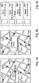
- FIG. 4a shows an exemplary embodiment of a display of a plurality of transport options TO1, TO2, TO3, TO4, TO5, TO6, TO7, TO8 on a map.
- Each transport option TO1, TO2, TO3, TO4, TO5, TO6, TO7, T08 can be selected by touching the associated symbol on the map.
- the particular current position X0 is also shown.
- Additional information E100 is indicated for transport option TO1.
- the driver for transport option TO1 is familiar to the user and his name is determined and displayed by means of a table entry.
- FIG. 4b shows an exemplary embodiment of a display for a confirmation ACK1 shown on the display of the passenger's device.
- FIG. 4c shows an exemplary embodiment of a display of a plurality of transport options TO1, TO2, T03, TO4 for a later time by means of a list.
- additional information E100 is output, which in the exemplary embodiment of FIG. 4c identifies a familiar person as the driver.
- FIG. 5 Another exemplary embodiment with a diagram is shown in FIG. 5 .
- a user 201 as passenger 201 is to take a trip from the start position X0 to the trip destination FT.
- the section covered by the trip from the start position X0 to trip destination FT is shown in FIG. 5 by a bar with the positions X0, X3, C, X4, FT and the sections P1, S1, S2, P2.
- the system is suitable for schedule planning by the central management of a plurality of data by a server 300.
- a timeline with the times t W , t X , t P1 , t 3 , t C , t 4 , t P2 , t F is shown below the illustration of the trip sections.
- Passenger 201 uses a mobile device 211, for example, a smartphone or smartbook.
- Mobile device 211 is configured to input the appointment time t F and the appointment place FT and optional a time interval ⁇ t1, ⁇ t2 by user 201.
- a time interval ⁇ t1, ⁇ t2 is entered.
- a first time interval ⁇ t1 between a start time t X and a time t P1 at the beginning of footpath P1 is entered.
- the first time interval ⁇ t1 takes into account a time period for leaving the house (e.g., 5 minutes).
- the second time interval ⁇ t2 defined between a time of arrival t P2 after the end of footpath P2 and the appointment time t F , takes into account, for example, a preparation time for the appointment (e.g., 5 minutes).
- the time intervals ⁇ t1, ⁇ t2 can also be set to zero.
- Mobile device 211 is configured to determine a current position X0 of mobile device 211.
- mobile device 211 has, for example, a GPS receiver.
- Server 300 can be connected to mobile device 211 via a network.
- a network For example, a UMTS connection or an LTE connection is used for this purpose.
- Mobile device 211 is configured to transmit the appointment time t F and the appointment place FT and the current position X0 and the time intervals ⁇ t1, ⁇ t2 to server 300.
- Server 300 is configured to determine traffic-related data RD as real-time data RD for at least one route section S1, S2 between the current position X0 and the appointment place FT.
- user 201 starts a short footpath P1 at the position X0 to location X3 where a first vehicle 410 transports user 201 as passenger 201 over a first route section S1 to location C.
- passenger 201 changes to second vehicle 420 and is driven over a second route section S2 to location X4.
- Passenger 201 leaves at location X4 and walks on another short footpath P2 to appointment place FT. How rapidly the first route section S1 and the second route section S2 can be covered depends significantly on traffic flow in these route sections S1, S2.
- other vehicles 430, 440, 450, 460 are shown which drive on route sections S1, S2.
- Server 300 is configured to determine traffic-related data RD of the particular route section S1, S2 based on an assessment of received vehicle-specific data M2 430 , M2 440 , M2 450 , M2 460 of vehicles 430, 440, 450, 460.
- the vehicle-specific data are, for example, a speed value M2 430 , M2 440 , M2 450 , M2 460 and/or an acceleration value and/or a value for the distance to a preceding and/or following vehicle and/or a value for route conditions and/or a vehicle density value. It is shown in the exemplary embodiment of FIG. 5 how vehicles 430, 440, 450, 460 each transmit a speed value M2 430 , M2 440 , M2 450 , M2 460 to server 300 over a wireless connection.
- Server 300 determines a travel time t T based on the data.
- the time for footpaths P1, P2 in this regard is substantially independent of traffic. From the speed values, server 300 calculates, for example, an average speed in route sections S1, S2 and in association with the length of route sections S1, S2 server 300 calculates the travel time t T .
- the start time t X can now be calculated by server 300, for example, by subtracting the travel time t T and subtracting the time intervals ⁇ t1, ⁇ t2 from the appointment time t F .
- Server 300 is configured, based on the appointment time t F and the appointment place FT and the current position X0 and possibly available time intervals ⁇ t1, ⁇ t2 and the traffic-related real-time data RD, to calculate the start time t X for traveling from current position X0 to the appointment place FT.
- the calculated start time t X is sent by server 300 to mobile device 211.
- Server 300 is configured to update continuously the start time t X based on the traffic-related data RD and to send it to mobile device 211. If the traffic situation in route sections S1, S2 changes, for example, due to black ice, this is taken into account in the calculation of the start time t X and the start time t X is accordingly adjusted forward.
- Mobile device 211 is configured to output an alarm A1, A2, A3 based on the start time t X and current time t.
- the alarm in this regard can be output in different ways.
- the alarm is indicated as a visual display A1 by a countdown.
- the display can blink in addition, for example, shortly before the start time t X is reached.
- the alarm is output alternatively or in addition by an acoustic signal A2.
- the acoustic signal A2 is, for example, an alarm sound and/or a voice output.
- the alarm is output alternatively or in addition by a vibration A3 of mobile device 211.
- a wake-up alarm WA can be set.
- a wake-up time t W can be specified by mobile device 211 and/or server 300.
- Mobile device 211 in this regard is configured to output the wake-up alarm WA, based on the wake-up time t W and the current time t.
- the wake-up alarm also has, for example, an alarm sound.
- FIG. 6 An exemplary embodiment with a display is shown schematically in FIG. 6 .
- a visual wake-up alarm WA an appointment time t F at the office, and a start time t X ' for the return trip and an arrival time t F ' at home are indicated.
- the arrival time t F ' could also be referred to as appointment time.
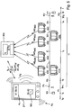
- FIGS. 7 and 8 A system of a motor vehicle 100 is shown in FIGS. 7 and 8 .
- the system has a central unit 130.
- Central unit 130 is connected to a driver terminal 129 for a driver 209 to output a route guidance.
- Driver terminal 129 is configured for inputting, for example, by means of sensors or a touchscreen. The driver can enter data via driver terminal 129 or he can operate functions.
- the system has three near field communication devices 111, 112, 113.
- Each near field communication device 111, 112, 113 is installed in motor vehicle 100 in the area of a seat for a mobile device 211, 212, 213.
- Each near field communication device 111, 112, 113 is connected to central unit 130.
- Each near field. communication device 111, 112, 113 can create a communication link with mobile device 211, 212, 213 located in the receptacle.
- the system has three display-input devices 121, 122, 123.
- Each display-input device 121, 122, 123 is installed in motor vehicle 100 for use by a passenger 201, 202, 203.
- Each display-input device 121, 122, 123 is connected to central unit 130.
- Near field communication device 111, 112, 113 and display-input device 121, 122, 123 are positioned for operation (operating) by passenger 201, 202, 203 at a passenger seat 101, 102, 103.
- Central unit 130 of the system is configured to read identification data ID211, ID212, ID213 from mobile device 211, 212, 213 of passenger 201, 202, 203 via near field communication device 111, 112, 113.
- the respective identification data ID211, ID212, ID213 are transmitted to central unit 130 from each mobile device 211, 212, 213 of passenger 201, 202, 203 via near field communication devices 111, 112, 113.
- Driver 209 can allow the identification data ID211, ID212, ID213 to be displayed via terminal 129. It is possible that central unit 130 is configured to transmit the identification data ID211, ID212, ID213 or the information associated therewith to server 300. The information can then be used for billing, e.g. for paying for the traveled sections.
- Central unit 130 is configured, based on the identification data ID211, ID212, ID213 from mobile devices 211, 212, 213, to activate display-input device 121, 122, 123 for use by passenger 201, 202, 203.
- passenger 201, 202, 203 can now allow data to be displayed or make entries.
- passenger 201, 202, 203 is authorized to allow image data from camera 164 to be displayed.
- music titles or video titles can be requested from a media database 155.
- Central unit 130 is configured, based on the identification data ID211, ID212, ID213, to permit access to data and/or services of central unit 130 of motor vehicle 100. Passenger 201, 202, 203 by the activation can also be permitted to access the infrastructure of vehicle 100, for example, a transceiver 140 of the wireless network connection (UMTS, LTE).
- UMTS wireless network connection
- central unit 130 is configured, based on the identification data ID211, ID212, ID213 from mobile devices 211, 212, 213, to transmit passenger-specific data D201, D202, D203 from central unit 130 for displaying on display-input device 121, 122, 123.
- passenger-specific data D201, D202, D203 are stored or generated in central unit 130.
- the passenger-specific data D201, D202, D203 have, for example, specific instructions for route guidance for passenger 201, 202, 203.
- the passenger-specific data D201, D202, D203 have a time counter until passenger 201, 202, 203 leaves motor vehicle 100 at a stop of the route guidance.
- the time counter is displayed by display-input device 121, 122, 123.
- passenger 201, 202, 203 is provided with the convenient option of accessing his own data, in that central unit 130 is configured, based on the identification data ID211, ID212, ID213, to permit access to data and/or services of mobile device 211, 212, 213 via near field communication device 111, 112, 113.
- central unit 130 is configured, based on the identification data ID211, ID212, ID213, to permit access to data and/or services of mobile device 211, 212, 213 via near field communication device 111, 112, 113.
- email can be read from mobile device 211, 212, 213 via near field communication device 111, 112, 113.
- An occupancy value B1, B2, B3 for the particular seat 101, 102, 103 is changed in central unit 130, based on the identification data ID211, ID212, ID213.
- the associated occupancy value B1, B2, B3 is set to "occupied.”
- seat 201, 202, 203 has an occupancy sensor 165, whereby the occupancy value B1, B2, B3 is set based on the sensor data of occupancy sensor 165.
- Central unit 130 is configured to provide the occupancy value B1, B2, B3 upon an inquiry by server 300 and occupancy values B1, B2, B3 are then transmitted from central unit 130 to server 300.
- the rider capacities are thus available to server 300 in real time. So that passenger 201 is informed in a timely manner about changing vehicles before location C is reached according to FIG. 3 , in the embodiment according to the invention of FIG. 7 central unit 130 is configured, based on the identification data ID211, ID212, ID213, to display a map by means of display-input device 121, 122, 123 with the current position of motor vehicle 100, 410 and/or a position of another motor vehicle 420, whereby the other motor vehicle 420 is assigned a trip route RT of passenger 201.
- the system has a WiFi access point 132 for a wireless connection.
- other devices for example, brought along by a passenger 201, 202, 203, can be included in the system via WiFi access point 132.
- the system of the exemplary embodiment of FIG. 7 has a number of audio amplifiers 153 and a number of loudspeakers 150.
- Central unit 130 of the present system has an interface 136 for receiving measured data M1, M2, M3, M4, M5, M6, M7, M8 from measurement sensors 161, 162, 163, 164, 165, 166, 167, 168 of motor vehicle 100.
- a measurement sensor is a camera 164 and/or a radar device 161 and/or a speed sensor 162 and/or a microphone 163 and/or an occupancy sensor 165 and/or a position sensor 166 and/or a street condition sensor/vibration sensor 168 and/or a temperature sensor 167 or the like.
- Central unit 130 is configured to activate a private mode M V or a public mode M c .
- the public mode M c is used here for information for other participants, who, e.g., as passengers require a ride or as a driver of another vehicle would like to be informed about the local situation, for example, by means of image data from camera 164.
- the private mode M v in contrast, makes it possible for driver 209 to protect his privacy, when, e.g., exclusively family members travel in the vehicle.
- Central unit 130 in the public mode M c is configured to activate a second configurable filter 132.
- a second selection of measured data M4, M6 and/or of input data E3 for transmission by transceiver 140 is released by means of the second configurable filter 132.
- the image data M4 of camera 164 and the position data M6 from position sensor 166 and a driving style category E3 are released for transmission.
- the second configurable filter 132 is shown in FIG. 9 as a function symbol and implemented, for example, by authorization software in central unit 130.
- the activation of the first configurable filter 131 or second configurable filter 132 is symbolized in FIG. 9 by a switch 133.
- central unit 130 has a configuration mode M K .
- Central unit 130 is configured to activate in the configuration mode M K an input mask to configure the first configurable filter 131 and/or second configurable filter 132.
- the configuration of filters 131, 132 can be fixedly predetermined or programmed via a connection.
- Central unit 130 is configured to transmit measured data M2, M4, M6 and/or input data E1, E3 released by means of the first configurable filter 131 or second configurable filter 132, when an inquiry Q is received over transceiver 140 about the particular measured data M2, M4, M6 and/or input data E1, E3.
- camera 164 is selected by the request from a vehicle 440 of the community and then the image data M4 are transmitted via server 300 to vehicle 440 and displayed there.
- one embodiment provides a system and a method to identify quasi real time vacancies for parking at the roadside as they occur randomly in the cities. These vacancies are made available to other traffic members in the community of the swarm. Such a member can be guided to such vacancy.
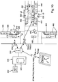
- a method for navigation is based on a plurality of vehicles 410, 420, 430, 440, 450, 460.
- the vehicles 410, 420, 430, 440, 450, 460 shown in FIG. 10 are members of the community.
- Each vehicle 410, 420, 430, 440, 450, 460 is connectable to a server 300 via a radio communication link.
- a base station 310 of a radio communication network is shown, which is connected to the server 300.
- the server 300 is not only specified as a hardware unit, but also could be a virtual server or be part of cloud.
- Each of the plurality of vehicles 410, 420, 430, 440, 450, 460 concurrently determines its current position X1, X2.
- all vehicle 410, 420 are moving.
- the vehicles 490 are objects.
- the vehicles 490 and the other object 480 are not moving and are parking or stationary.
- three vacancies 510, 520, 530 for parking are shown. These vacancies 510, 520, 530 are a gap between two parked vehicles 490 or between a parked vehicle 490 and the other object 480, e.g. a flower tub.
- a vehicle 410 is currently determining one vacancy 510 for parking based on recognized objects 480, 490 at the roadside.
- the system of the vehicle 410 has an object recognition device 161, 164 as shown in FIG. 7 .
- a video camera 164 and/or a radar sensor 161 are an essential part of an object recognition device.
- another vehicle 420 is currently determining one vacancy 520 for parking based on recognized objects 490 at the left roadside and one vacancy 530 for parking based on recognized objects 490 at the right roadside.
- the vehicle 410 may determine its current position X1 based on GPS-satellite signals. Depending on its current position X1 the vehicle 410 may determine the position P510 of the vacancy.
- the vehicle 420 is determining positions P520 and P530 of the vacancies 520, 530 based on its current position X2. As shown in FIG. 10 both vehicles 410, 420 are configured to transmit the positions P510, P520, P530 of the vacancies 510, 520, 530 together with the length L1, L2, L3 of each vacancy 510, 520, 530 to the connected server 300 via the base station 310.
- the vacancies 510, 520, 530 for parking are received by the server 300.
- the server 300 enables the storing of the positions P510, P520, P530 of the vacancies 510, 520, 530 in an internal storage 320 or external storage 320' connected to the server 300.
- the storage may be organized as a database.
- the aforementioned steps describe how the vacancies 510, 520, 530 for parking are fed into the storage 320, 320'. In the following the steps concerning the request and retrieval of the positions P510, P520, P530 of the vacancies 510, 520, 530 are described.
- an input by a user 209 of a query QP is determined.
- the query QP concerns vacancies for parking.
- the query QP together with a final destination F1 is transmitted from the user 209 to the server 300 via the base station 310.
- positions P540, P550, P560, P570, P580 of vacancies 540, 550, 560, 570, 580 are transmitted from the server 300 to the user 209.
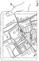
- FIG. 11 shows a map with an area PA around the final destination F1. Positions P540, P550, P560, P570, P580 of vacancies 540, 550, 560, 570, 580 are shown by parking symbols within the area PA. The symbols may further be used for navigation.
- a selection of a vacancy 540 for parking is determined, if the user 209 is touching the associated symbol.
- the position P540 of the vacancy 540 is set to be a new final destination P540.
- the route guidance to the new final destination P540 is started afterwards. It is also possible to calculate a round tour passing several or all of the positions P540, P550, P560, P570, P580 of vacancies 540, 550, 560, 570, 580, e.g. after reaching the final destination F1.
- an occupation information may be sent from the user 209 to the server 300, if the position P540 is occupied by another vehicle or if a reaching of the position P540 of the vacancy 540 for parking by the user 209 is determined.
- the server 300 After the server 300 has received the occupation information the stored position P540 may be deleted in the storage 320, 320' by the server 300.
- the vacancies 540, 550, 560, 570, 580 for parking may be concurrently updated.
- the updating may be terminated, when a parking of the vehicle of the user 209 is detected or if the user switches off the updating, e.g. by a respective input.
- the area PA may be determined geographically, e.g. by determining each distance to the final destination F1 and comparing it with an area threshold. Alternatively the area PA is defined by a number of closest vacancies, e.g. the position of the ten closest vacancies define the area PA.
- the user 209 in FIG. 11 may select a vacancy for reservation.
- a selection for reservation is determined, e.g. if the user 209 is touching a symbol of one vacancy for parking.
- a reservation information R P540 is transmitted from the user 209 to the server 300 as shown in FIG. 10 . E.g. for a period of time this vacancy is not retrievable for other members of the community.
- an authentication of the user 209 to be a member of a group legitimated to retrieve vacancies 540, 550, 560, 570, 580 occurs.
- the positions P540, P550, P560, P570, P580 are transmitted only after the authentication is successfully completed.
- a length L1, L2, L3 of each vacancy 510, 520, 530 is determined and transmitted along with each position P510, P520, P530 from the respective vehicle 410, 420 to the connected server 300.
- the server 300 may transmit only that vacancies suitable for the user 209.
- all positions of all vacancies are transmitted to the user along with the respective length of each vacancy.
- the vacancies may be selected by a user's program.
- each vacancy may be selected depending on its lengths L1, L2, L3. After selection only fitting vacancies may be displayed for navigation.
- the behaviour of other vehicles which are not a member of the community are taken into account.
- a point in time of the determination of the vacancy 510, 520, 530 may be determined and the point in time may be stored along with the position P510, P520, P530 by the server 300.
- the positions P540, P550, P560, P570, P580 of vacancies 540, 550, 560, 570, 580 and respective points of time are transmitted from the server 300 to the user 209.
- the points of time could be used for navigation in several ways.
- FIG. 11 visualization is shown. Using at least one time threshold vacancies may be categorized comparing a difference of the points of time and the current time with the at least one time threshold.
Landscapes
- Engineering & Computer Science (AREA)
- Computer Networks & Wireless Communication (AREA)
- Signal Processing (AREA)
- Radar, Positioning & Navigation (AREA)
- Remote Sensing (AREA)
- Automation & Control Theory (AREA)
- Physics & Mathematics (AREA)
- General Physics & Mathematics (AREA)
- Navigation (AREA)
- Traffic Control Systems (AREA)
Claims (10)
- Verfahren zur Navigierung von Fahrzeugen (100, 410, 420, 430, 440, 450, 460) mit mindestens einem ersten Fahrzeug (410) und einem zweiten Fahrzeug (420), wobei die Fahrzeuge (100, 410, 420, 430, 440, 450, 460) zu einer Gemeinschaft (400) gehören und über eine Drahtlosverbindung (340) Daten mit einem Server (300) austauschen, wobei das Verfahren die folgenden Schritte umfasst:Übertragen einer ersten aktuellen Position (X1) des ersten Fahrzeugs (410) von dem ersten Fahrzeug (410) an den Server (300),Übertragen einer zweiten aktuellen Position (X2) des zweiten Fahrzeugs (420) von dem zweiten Fahrzeug (420) an den Server (300),Bestimmen einer ersten Route (R1) und einer zweiten Route (R2) mit Hilfe des Servers (300),wobei die erste Route (R1) von der ersten aktuellen Position (X1) zu einem ersten Endziel (F1) des ersten Fahrzeugs (410) bestimmt wird,wobei die zweite Route (R2) von der zweiten aktuellen Position (X2) zu einem zweiten Endziel (F2) des zweiten Fahrzeugs (420) bestimmt wird,wobei eine Position (C) die erste Route (R1) und die zweite Route (R2) als Zwischenziel miteinander verbindet, sodass ein Fahrgast (201) in der Lage ist, von dem ersten Fahrzeug (410) zu dem zweiten Fahrzeug (420) zu wechseln,wobei die Position (C) in der ersten Route (R1) und in der zweiten Route (R2) enthalten ist,Übertragen der ersten Route (R1) an das erste Fahrzeug (410),Übertragen der zweiten Route (R2) an das zweite Fahrzeug (420),dadurch gekennzeichnet, dass das Verfahren ferner die folgenden Schritte umfasst:Anzeigen einer Karte mit der aktuellen Position des ersten Fahrzeugs (410) und der aktuellen Position des zweiten Fahrzeuges (420), die den Fahrgast (201) über den Wechsel der Fahrzeuge (410, 420) informiert, bevor die Position (C) erreicht ist, auf einer Anzeige einer Zentraleinheit des ersten Fahrzeugs (410); undBerechnen einer Leerstellenzuordnung von Parkleerstellen für Fahrzeuge der Gemeinschaft (400) durch Verringern der zu Fuß zurückzulegenden Entfernungen zwischen den Zielen und den Positionen der Leerstellen für eine Mehrzahl von Fahrzeugen, die aneinander angrenzende Ziele aufweisen; undÜbertagen der Positionen der Leerstellen in einem Bereich um das Zwischenziel (C) herum auf Grundlage der Leerstellenzuordnung von dem Server (300) an das erste Fahrzeug (410) und das zweite Fahrzeug (420) zur Navigation.
- Verfahren nach Anspruch 1, umfassend die folgenden Schritte:Übertragen einer Anfrage (RQ) von einer Vorrichtung (211) an den Server (300),wobei die Anfrage (RQ) eine aktuelle Fahrgastposition (X0) des Fahrgasts (201) undein Fahrgastziel (FT) enthält,Bestimmen einer Transportoption (TO) eines Transports des Fahrgasts (201) mit Hilfe des ersten Fahrzeugs (410) und des zweiten Fahrzeugs (420) an das Fahrgastziel (FT),wobei die Bestimmung auf mindestens einer der folgenden Positionen basiert:der aktuellen Fahrgastposition (X0) undder ersten aktuellen Position (X1) des ersten Fahrzeugs (410) undder zweiten aktuellen Position (X2) des zweiten Fahrzeugs (420) undeiner aktuellen Route des ersten Fahrzeugs (410) undeinem Endziel (F1) des ersten Fahrzeugs (410) undeiner aktuellen Route des zweiten Fahrzeugs (420) undeinem Endziel (F2) des zweiten Fahrzeugs (420) undeinem oder mehreren ersten Parametern (B1, B2, B3, M, E2, E3, E4, E5) der Transportoption (TO), wobei die ersten Parameter (B1, B2, B3, M, E2, E3, E4, E5) von dem ersten Fahrzeug (410) an den Server (300) übertragen werden, undeinem oder mehreren zweiten Parametern (B1, B2, B3, M, E2, E3, E4, E5) der Transportoption (TO), wobei die zweiten Parameter (B1, B2, B3, M, E2, E3, E4, E5) von dem zweiten Fahrzeug (420) an den Server (300) übertragen werden,Anzeigen der Transportoption (TO) zur Eingabe einer Auswahl (SC).
- Verfahren nach Anspruch 2, wobei einer der ersten Parameter (B1, B2, B3, M, E2, E3, E4, E5) und/oder einer der zweiten Parameter (B1, B2, B3, M, E2, E3, E4, E5) Folgendes enthält:einen Moduswert (M) für einen privaten Modus (Mv) ohne Transport von Fahrgästen oder einen öffentlichen Modus (Mc) mit Transport von Fahrgästen und/oder einen Entfernungswert (E5) für einen maximalen Umweg und/oder einen Belegungswert (B1, B2, B3) für eine Anzahl leerstehender Transportplätze (101, 102, 103) des Fahrzeugs (100, 410, 420) und/odereinen Gruppenindex (E4) für eine Angliederung an eine bestimmte Personengruppe und/oderein einstellbares Profil (E2, E3) des Fahrers (209) für Präferenzen.
- Verfahren nach einem der Ansprüche 2 oder 3, umfassend den folgenden Schritt:Bestimmen der ersten Route (R1) und der zweiten Route (R2), wenn die Auswahleingabe (SC) bestimmt wird, und insbesondere, wenn eine erste Bestätigung (ACK1) von einem ersten Fahrer des ersten Fahrzeugs (410) und eine zweite Bestätigung (ACK2) von einem zweiten Fahrer des zweiten Fahrzeugs (420) bestimmt wird.
- Verfahren nach einem der vorstehenden Ansprüche, umfassend die folgenden Schritte:Ausgeben der Position (C) als erste Zwischenposition in einer ersten Routenführung der ersten Route (R1) undAusgeben der Position (C) als zweite Zwischenposition in einer zweiten Routenführung der zweiten Route (R2).
- Verfahren nach einem der vorstehenden Ansprüche, umfassend den folgenden Schritt:Ausgeben von Informationen an den Fahrgast (201), wobei die Informationen auf der Position (C) basieren, insbesondere von einem Zeitzählwert bis zum Erreichen der Position (C).
- Verfahren nach Anspruch 1, umfassend die folgenden Schritte:Anzeigen einer Karte und Anzeigen einer Mehrzahl von Transportoptionen (TO1, TO2, TO3, TO4, TO5, TO6, TO7, TO8) auf den Karten undAuswählen einer der Transportoptionen (TO1, TO2, TO3, TO4, TO5, TO6, TO7, TO8) durch Berühren eines dieser zugeordneten Symbole auf der Karte.
- Verfahren nach Anspruch 2 und 8, umfassend den folgenden Schritt:Senden einer Anfrage an das erste Fahrzeug (410) für eine Bestätigung des Fahrers, wenn eine Transportoption (TO1) ausgewählt wird.
- Verfahren nach Anspruch 2 und 8, umfassend den folgenden Schritt:Senden einer Anfrage an das zweite Fahrzeug (420) für eine Bestätigung des Fahrers, wenn eine Transportoption (TO1) ausgewählt wird.
- System zur Navigierung von Fahrzeugen (100, 410, 420, 430, 440, 450, 460), die zu einer Gemeinschaft (400) gehören und über eine Drahtlosverbindung (340) Daten mit einem Server (300) austauschen, wobei das System mindestens ein erstes Fahrzeug (410) und ein zweites Fahrzeug (420) und den Server (300) umfasst, der mit Hilfe einer Drahtlosdatenübertragung mit dem ersten Fahrzeug (410) und dem zweiten Fahrzeug (420) verbindbar ist,
wobei das erste Fahrzeug (410) derart konfiguriert ist, dass es eine erste aktuelle Position (X1) des ersten Fahrzeugs (410) an den Server (300) überträgt,
wobei das zweite Fahrzeug (420) derart konfiguriert ist, dass es eine zweite aktuelle Position (X2) des zweiten Fahrzeugs (420) an den Server (300) überträgt,
wobei der Server (300) derart konfiguriert ist, dass er eine erste Route (R1) und eine zweite Route (R2) bestimmt,
wobei die erste Route (R1) von der ersten aktuellen Position (X1) zu einem ersten Endziel (F1) des ersten Fahrzeugs (410) definiert ist,
wobei die zweite Route (R2) von der zweiten aktuellen Position (X2) zu einem zweiten Endziel (F2) des zweiten Fahrzeugs (420) definiert ist,
wobei eine Position (C) die erste Route (R1) und die zweite Route (R2) als Zwischenziel derart miteinander verbindet, dass ein Fahrgast (201) in der Lage ist, von dem ersten Fahrzeug (410) zu dem zweiten Fahrzeug (420) zu wechseln,
wobei die Position (C) in der ersten Route (R1) und in der zweiten Route (R2) enthalten ist,
wobei der Server (300) derart konfiguriert ist, dass er die erste Route (R1) an das erste Fahrzeug (410) und die zweite Route (R2) an das zweite Fahrzeug (420) überträgt, dadurch gekennzeichnet, dass die erste Einheit (410) eine Zentraleinheit umfasst, die derart konfiguriert ist, dass sie auf einer Anzeige der Zentraleinheit eine Karte mit der aktuellen Position des ersten Fahrzeugs (410) und der aktuellen Position des zweiten Fahrzeuges (420) anzeigt, die den Fahrgast (201) über den Wechsel der Fahrzeuge (410, 420) informiert, bevor die Position (C) erreicht ist, und
wobei der Server (300) derart konfiguriert ist, dass er eine Leerstellenzuordnung von Parkleerstellen für Fahrzeuge der Gemeinschaft (400) durch Verringern der zu Fuß zurückzulegenden Entfernungen zwischen den Zielen und den Positionen der Leerstellen für eine Mehrzahl von Fahrzeugen berechnet, die aneinander angrenzende Ziele aufweisen, und
wobei der Server (300) derart konfiguriert ist, dass er Positionen der Leerstellen in dem Bereich um das Zwischenziel (C) herum auf Grundlage der Leerstellenzuordnung an das erste Fahrzeug (410) und das zweite Fahrzeug (420) zur Navigation sendet.
Priority Applications (2)
| Application Number | Priority Date | Filing Date | Title |
|---|---|---|---|
| EP16172103.0A EP3093621A1 (de) | 2013-02-18 | 2013-02-18 | Verfahren und system zur navigation |
| EP13000822.0A EP2767802B1 (de) | 2013-02-18 | 2013-02-18 | Verfahren und System zur Navigation |
Applications Claiming Priority (1)
| Application Number | Priority Date | Filing Date | Title |
|---|---|---|---|
| EP13000822.0A EP2767802B1 (de) | 2013-02-18 | 2013-02-18 | Verfahren und System zur Navigation |
Related Child Applications (1)
| Application Number | Title | Priority Date | Filing Date |
|---|---|---|---|
| EP16172103.0A Division EP3093621A1 (de) | 2013-02-18 | 2013-02-18 | Verfahren und system zur navigation |
Publications (2)
| Publication Number | Publication Date |
|---|---|
| EP2767802A1 EP2767802A1 (de) | 2014-08-20 |
| EP2767802B1 true EP2767802B1 (de) | 2016-06-08 |
Family
ID=47738993
Family Applications (2)
| Application Number | Title | Priority Date | Filing Date |
|---|---|---|---|
| EP13000822.0A Active EP2767802B1 (de) | 2013-02-18 | 2013-02-18 | Verfahren und System zur Navigation |
| EP16172103.0A Withdrawn EP3093621A1 (de) | 2013-02-18 | 2013-02-18 | Verfahren und system zur navigation |
Family Applications After (1)
| Application Number | Title | Priority Date | Filing Date |
|---|---|---|---|
| EP16172103.0A Withdrawn EP3093621A1 (de) | 2013-02-18 | 2013-02-18 | Verfahren und system zur navigation |
Country Status (1)
| Country | Link |
|---|---|
| EP (2) | EP2767802B1 (de) |
Families Citing this family (2)
| Publication number | Priority date | Publication date | Assignee | Title |
|---|---|---|---|---|
| DE102017115706A1 (de) | 2017-07-12 | 2019-01-17 | Dr. Ing. H.C. F. Porsche Aktiengesellschaft | Verfahren und Vorrichtung zur Kommunikation |
| JP7408201B2 (ja) * | 2022-01-06 | 2024-01-05 | 株式会社パークランド | 貸出し車両管理システムおよびプログラム |
Citations (1)
| Publication number | Priority date | Publication date | Assignee | Title |
|---|---|---|---|---|
| EP1339247A2 (de) * | 2002-02-26 | 2003-08-27 | Vodafone Holding GmbH | Verfahren zum Erzeugen von Informationsdaten für mobile Nutzer eines Informations-Übertragungssytems |
Family Cites Families (4)
| Publication number | Priority date | Publication date | Assignee | Title |
|---|---|---|---|---|
| US6697730B2 (en) * | 2000-04-04 | 2004-02-24 | Georgia Tech Research Corp. | Communications and computing based urban transit system |
| EP1168275A1 (de) * | 2000-06-30 | 2002-01-02 | Nokia Networks Oy | Mitfahrersystem und -Verfahren |
| DE10119244A1 (de) * | 2001-04-19 | 2003-01-23 | Ferdinand Peer | Verfahren zur Vermittlung und/oder Überwachung einer Reise von Reisenden |
| US7177738B2 (en) | 2001-05-30 | 2007-02-13 | Alpine Electronics, Inc. | Vehicle management system |
-
2013
- 2013-02-18 EP EP13000822.0A patent/EP2767802B1/de active Active
- 2013-02-18 EP EP16172103.0A patent/EP3093621A1/de not_active Withdrawn
Patent Citations (1)
| Publication number | Priority date | Publication date | Assignee | Title |
|---|---|---|---|---|
| EP1339247A2 (de) * | 2002-02-26 | 2003-08-27 | Vodafone Holding GmbH | Verfahren zum Erzeugen von Informationsdaten für mobile Nutzer eines Informations-Übertragungssytems |
Also Published As
| Publication number | Publication date |
|---|---|
| EP2767802A1 (de) | 2014-08-20 |
| EP3093621A1 (de) | 2016-11-16 |
Similar Documents
| Publication | Publication Date | Title |
|---|---|---|
| EP2767962A1 (de) | System und Verfahren zur Kommunikation für ein Motorfahrzeug | |
| EP2767963B1 (de) | System und Verfahren zur automatischen Planung | |
| US10019682B2 (en) | Unauthorized vehicle detection | |
| US20210223051A1 (en) | Systems and methods for vehicle ridesharing | |
| CN111276005B (zh) | 联网停车系统 | |
| JP4486650B2 (ja) | 車両シェア管理装置および車両シェア管理方法 | |
| EP2836792B1 (de) | Routennavigation auf parkgrundlage | |
| EP2836990B1 (de) | Parkressourcenverwaltung | |
| US11604464B2 (en) | Virtual valet | |
| TWI428249B (zh) | 車載裝置及其行車輔助系統與行車輔助資訊提供方法 | |
| US12259727B2 (en) | Multiple destination trips for autonomous vehicles | |
| US20160061618A1 (en) | Technique for navigating a vehicle to a parking place | |
| US20160320195A1 (en) | Ride-sharing long-term ride-share groups | |
| JP4976589B2 (ja) | 駐車場管理装置 | |
| KR101957641B1 (ko) | 버스 정보 안내 시스템과 주차장 관리 시스템을 연동하여 주차 예약 및 이동 경로 탐색을 위한 교통 통합 관제 시스템 및 그의 처리 방법 | |
| CN105469627A (zh) | 一种车位预约方法及装置、车位预约系统 | |
| CN105096079A (zh) | 按需运输 | |
| EP3276307A1 (de) | Verwaltungsvorrichtung für ein gemeinsam genutztes fahrzeug und verwaltungsverfahren für ein gemeinsam genutztes fahrzeug | |
| CN113450466A (zh) | 自动代客停车场的管理装置 | |
| KR20140075880A (ko) | 주차 예약 관리시스템 장치 및 그 주차 예약 관리방법 | |
| EP2767803B1 (de) | Verfahren und System zur Navigation | |
| EP2767802A1 (de) | Verfahren und System zur Navigation | |
| EP2767961A1 (de) | Verfahren und System eines Fahrzeugs | |
| JP6333433B1 (ja) | 情報処理装置、車両探索方法及びプログラム | |
| US11071204B2 (en) | Parking management system |
Legal Events
| Date | Code | Title | Description |
|---|---|---|---|
| PUAI | Public reference made under article 153(3) epc to a published international application that has entered the european phase |
Free format text: ORIGINAL CODE: 0009012 |
|
| 17P | Request for examination filed |
Effective date: 20131119 |
|
| AK | Designated contracting states |
Kind code of ref document: A1 Designated state(s): AL AT BE BG CH CY CZ DE DK EE ES FI FR GB GR HR HU IE IS IT LI LT LU LV MC MK MT NL NO PL PT RO RS SE SI SK SM TR |
|
| AX | Request for extension of the european patent |
Extension state: BA ME |
|
| REG | Reference to a national code |
Ref country code: DE Ref legal event code: R079 Ref document number: 602013008296 Country of ref document: DE Free format text: PREVIOUS MAIN CLASS: G01C0021340000 Ipc: G08G0001000000 |
|
| RIC1 | Information provided on ipc code assigned before grant |
Ipc: G01C 21/34 20060101ALI20151019BHEP Ipc: G08G 1/00 20060101AFI20151019BHEP |
|
| GRAP | Despatch of communication of intention to grant a patent |
Free format text: ORIGINAL CODE: EPIDOSNIGR1 |
|
| INTG | Intention to grant announced |
Effective date: 20151218 |
|
| GRAS | Grant fee paid |
Free format text: ORIGINAL CODE: EPIDOSNIGR3 |
|
| GRAA | (expected) grant |
Free format text: ORIGINAL CODE: 0009210 |
|
| AK | Designated contracting states |
Kind code of ref document: B1 Designated state(s): AL AT BE BG CH CY CZ DE DK EE ES FI FR GB GR HR HU IE IS IT LI LT LU LV MC MK MT NL NO PL PT RO RS SE SI SK SM TR |
|
| REG | Reference to a national code |
Ref country code: GB Ref legal event code: FG4D |
|
| REG | Reference to a national code |
Ref country code: CH Ref legal event code: EP |
|
| REG | Reference to a national code |
Ref country code: IE Ref legal event code: FG4D |
|
| REG | Reference to a national code |
Ref country code: AT Ref legal event code: REF Ref document number: 805719 Country of ref document: AT Kind code of ref document: T Effective date: 20160715 |
|
| REG | Reference to a national code |
Ref country code: DE Ref legal event code: R096 Ref document number: 602013008296 Country of ref document: DE |
|
| REG | Reference to a national code |
Ref country code: LT Ref legal event code: MG4D |
|
| REG | Reference to a national code |
Ref country code: NL Ref legal event code: MP Effective date: 20160608 |
|
| PG25 | Lapsed in a contracting state [announced via postgrant information from national office to epo] |
Ref country code: LT Free format text: LAPSE BECAUSE OF FAILURE TO SUBMIT A TRANSLATION OF THE DESCRIPTION OR TO PAY THE FEE WITHIN THE PRESCRIBED TIME-LIMIT Effective date: 20160608 Ref country code: FI Free format text: LAPSE BECAUSE OF FAILURE TO SUBMIT A TRANSLATION OF THE DESCRIPTION OR TO PAY THE FEE WITHIN THE PRESCRIBED TIME-LIMIT Effective date: 20160608 Ref country code: NO Free format text: LAPSE BECAUSE OF FAILURE TO SUBMIT A TRANSLATION OF THE DESCRIPTION OR TO PAY THE FEE WITHIN THE PRESCRIBED TIME-LIMIT Effective date: 20160908 |
|
| REG | Reference to a national code |
Ref country code: AT Ref legal event code: MK05 Ref document number: 805719 Country of ref document: AT Kind code of ref document: T Effective date: 20160608 |
|
| PG25 | Lapsed in a contracting state [announced via postgrant information from national office to epo] |
Ref country code: NL Free format text: LAPSE BECAUSE OF FAILURE TO SUBMIT A TRANSLATION OF THE DESCRIPTION OR TO PAY THE FEE WITHIN THE PRESCRIBED TIME-LIMIT Effective date: 20160608 Ref country code: GR Free format text: LAPSE BECAUSE OF FAILURE TO SUBMIT A TRANSLATION OF THE DESCRIPTION OR TO PAY THE FEE WITHIN THE PRESCRIBED TIME-LIMIT Effective date: 20160909 Ref country code: SE Free format text: LAPSE BECAUSE OF FAILURE TO SUBMIT A TRANSLATION OF THE DESCRIPTION OR TO PAY THE FEE WITHIN THE PRESCRIBED TIME-LIMIT Effective date: 20160608 Ref country code: HR Free format text: LAPSE BECAUSE OF FAILURE TO SUBMIT A TRANSLATION OF THE DESCRIPTION OR TO PAY THE FEE WITHIN THE PRESCRIBED TIME-LIMIT Effective date: 20160608 Ref country code: LV Free format text: LAPSE BECAUSE OF FAILURE TO SUBMIT A TRANSLATION OF THE DESCRIPTION OR TO PAY THE FEE WITHIN THE PRESCRIBED TIME-LIMIT Effective date: 20160608 Ref country code: RS Free format text: LAPSE BECAUSE OF FAILURE TO SUBMIT A TRANSLATION OF THE DESCRIPTION OR TO PAY THE FEE WITHIN THE PRESCRIBED TIME-LIMIT Effective date: 20160608 Ref country code: ES Free format text: LAPSE BECAUSE OF FAILURE TO SUBMIT A TRANSLATION OF THE DESCRIPTION OR TO PAY THE FEE WITHIN THE PRESCRIBED TIME-LIMIT Effective date: 20160608 |
|
| REG | Reference to a national code |
Ref country code: FR Ref legal event code: PLFP Year of fee payment: 5 |
|
| PG25 | Lapsed in a contracting state [announced via postgrant information from national office to epo] |
Ref country code: EE Free format text: LAPSE BECAUSE OF FAILURE TO SUBMIT A TRANSLATION OF THE DESCRIPTION OR TO PAY THE FEE WITHIN THE PRESCRIBED TIME-LIMIT Effective date: 20160608 Ref country code: IS Free format text: LAPSE BECAUSE OF FAILURE TO SUBMIT A TRANSLATION OF THE DESCRIPTION OR TO PAY THE FEE WITHIN THE PRESCRIBED TIME-LIMIT Effective date: 20161008 Ref country code: SK Free format text: LAPSE BECAUSE OF FAILURE TO SUBMIT A TRANSLATION OF THE DESCRIPTION OR TO PAY THE FEE WITHIN THE PRESCRIBED TIME-LIMIT Effective date: 20160608 Ref country code: RO Free format text: LAPSE BECAUSE OF FAILURE TO SUBMIT A TRANSLATION OF THE DESCRIPTION OR TO PAY THE FEE WITHIN THE PRESCRIBED TIME-LIMIT Effective date: 20160608 Ref country code: CZ Free format text: LAPSE BECAUSE OF FAILURE TO SUBMIT A TRANSLATION OF THE DESCRIPTION OR TO PAY THE FEE WITHIN THE PRESCRIBED TIME-LIMIT Effective date: 20160608 Ref country code: IT Free format text: LAPSE BECAUSE OF FAILURE TO SUBMIT A TRANSLATION OF THE DESCRIPTION OR TO PAY THE FEE WITHIN THE PRESCRIBED TIME-LIMIT Effective date: 20160608 |
|
| PG25 | Lapsed in a contracting state [announced via postgrant information from national office to epo] |
Ref country code: SM Free format text: LAPSE BECAUSE OF FAILURE TO SUBMIT A TRANSLATION OF THE DESCRIPTION OR TO PAY THE FEE WITHIN THE PRESCRIBED TIME-LIMIT Effective date: 20160608 Ref country code: PL Free format text: LAPSE BECAUSE OF FAILURE TO SUBMIT A TRANSLATION OF THE DESCRIPTION OR TO PAY THE FEE WITHIN THE PRESCRIBED TIME-LIMIT Effective date: 20160608 Ref country code: PT Free format text: LAPSE BECAUSE OF FAILURE TO SUBMIT A TRANSLATION OF THE DESCRIPTION OR TO PAY THE FEE WITHIN THE PRESCRIBED TIME-LIMIT Effective date: 20161010 Ref country code: AT Free format text: LAPSE BECAUSE OF FAILURE TO SUBMIT A TRANSLATION OF THE DESCRIPTION OR TO PAY THE FEE WITHIN THE PRESCRIBED TIME-LIMIT Effective date: 20160608 Ref country code: BE Free format text: LAPSE BECAUSE OF FAILURE TO SUBMIT A TRANSLATION OF THE DESCRIPTION OR TO PAY THE FEE WITHIN THE PRESCRIBED TIME-LIMIT Effective date: 20160608 |
|
| REG | Reference to a national code |
Ref country code: DE Ref legal event code: R097 Ref document number: 602013008296 Country of ref document: DE |
|
| PLBE | No opposition filed within time limit |
Free format text: ORIGINAL CODE: 0009261 |
|
| STAA | Information on the status of an ep patent application or granted ep patent |
Free format text: STATUS: NO OPPOSITION FILED WITHIN TIME LIMIT |
|
| 26N | No opposition filed |
Effective date: 20170309 |
|
| PG25 | Lapsed in a contracting state [announced via postgrant information from national office to epo] |
Ref country code: DK Free format text: LAPSE BECAUSE OF FAILURE TO SUBMIT A TRANSLATION OF THE DESCRIPTION OR TO PAY THE FEE WITHIN THE PRESCRIBED TIME-LIMIT Effective date: 20160608 Ref country code: SI Free format text: LAPSE BECAUSE OF FAILURE TO SUBMIT A TRANSLATION OF THE DESCRIPTION OR TO PAY THE FEE WITHIN THE PRESCRIBED TIME-LIMIT Effective date: 20160608 |
|
| PG25 | Lapsed in a contracting state [announced via postgrant information from national office to epo] |
Ref country code: MC Free format text: LAPSE BECAUSE OF FAILURE TO SUBMIT A TRANSLATION OF THE DESCRIPTION OR TO PAY THE FEE WITHIN THE PRESCRIBED TIME-LIMIT Effective date: 20160608 |
|
| REG | Reference to a national code |
Ref country code: CH Ref legal event code: PL |
|
| PG25 | Lapsed in a contracting state [announced via postgrant information from national office to epo] |
Ref country code: CH Free format text: LAPSE BECAUSE OF NON-PAYMENT OF DUE FEES Effective date: 20170228 Ref country code: LI Free format text: LAPSE BECAUSE OF NON-PAYMENT OF DUE FEES Effective date: 20170228 |
|
| REG | Reference to a national code |
Ref country code: IE Ref legal event code: MM4A |
|
| PG25 | Lapsed in a contracting state [announced via postgrant information from national office to epo] |
Ref country code: LU Free format text: LAPSE BECAUSE OF NON-PAYMENT OF DUE FEES Effective date: 20170218 |
|
| REG | Reference to a national code |
Ref country code: FR Ref legal event code: PLFP Year of fee payment: 6 |
|
| PG25 | Lapsed in a contracting state [announced via postgrant information from national office to epo] |
Ref country code: IE Free format text: LAPSE BECAUSE OF NON-PAYMENT OF DUE FEES Effective date: 20170218 |
|
| PG25 | Lapsed in a contracting state [announced via postgrant information from national office to epo] |
Ref country code: MT Free format text: LAPSE BECAUSE OF NON-PAYMENT OF DUE FEES Effective date: 20170218 |
|
| PG25 | Lapsed in a contracting state [announced via postgrant information from national office to epo] |
Ref country code: AL Free format text: LAPSE BECAUSE OF FAILURE TO SUBMIT A TRANSLATION OF THE DESCRIPTION OR TO PAY THE FEE WITHIN THE PRESCRIBED TIME-LIMIT Effective date: 20160608 |
|
| PG25 | Lapsed in a contracting state [announced via postgrant information from national office to epo] |
Ref country code: HU Free format text: LAPSE BECAUSE OF FAILURE TO SUBMIT A TRANSLATION OF THE DESCRIPTION OR TO PAY THE FEE WITHIN THE PRESCRIBED TIME-LIMIT; INVALID AB INITIO Effective date: 20130218 |
|
| PG25 | Lapsed in a contracting state [announced via postgrant information from national office to epo] |
Ref country code: BG Free format text: LAPSE BECAUSE OF FAILURE TO SUBMIT A TRANSLATION OF THE DESCRIPTION OR TO PAY THE FEE WITHIN THE PRESCRIBED TIME-LIMIT Effective date: 20160608 |
|
| PG25 | Lapsed in a contracting state [announced via postgrant information from national office to epo] |
Ref country code: CY Free format text: LAPSE BECAUSE OF NON-PAYMENT OF DUE FEES Effective date: 20160608 |
|
| PG25 | Lapsed in a contracting state [announced via postgrant information from national office to epo] |
Ref country code: MK Free format text: LAPSE BECAUSE OF FAILURE TO SUBMIT A TRANSLATION OF THE DESCRIPTION OR TO PAY THE FEE WITHIN THE PRESCRIBED TIME-LIMIT Effective date: 20160608 |
|
| PG25 | Lapsed in a contracting state [announced via postgrant information from national office to epo] |
Ref country code: TR Free format text: LAPSE BECAUSE OF FAILURE TO SUBMIT A TRANSLATION OF THE DESCRIPTION OR TO PAY THE FEE WITHIN THE PRESCRIBED TIME-LIMIT Effective date: 20160608 |
|
| PGFP | Annual fee paid to national office [announced via postgrant information from national office to epo] |
Ref country code: FR Payment date: 20200122 Year of fee payment: 8 |
|
| REG | Reference to a national code |
Ref country code: DE Ref legal event code: R082 Ref document number: 602013008296 Country of ref document: DE Representative=s name: MAUCHER JENKINS PATENTANWAELTE & RECHTSANWAELT, DE |
|
| PG25 | Lapsed in a contracting state [announced via postgrant information from national office to epo] |
Ref country code: FR Free format text: LAPSE BECAUSE OF NON-PAYMENT OF DUE FEES Effective date: 20210228 |
|
| P01 | Opt-out of the competence of the unified patent court (upc) registered |
Effective date: 20230526 |
|
| PGFP | Annual fee paid to national office [announced via postgrant information from national office to epo] |
Ref country code: GB Payment date: 20260121 Year of fee payment: 14 |
|
| PGFP | Annual fee paid to national office [announced via postgrant information from national office to epo] |
Ref country code: DE Payment date: 20260121 Year of fee payment: 14 |