EP2767846A1 - Procédé d'étalonnage d'un groupe de capteurs dans un véhicule automobile - Google Patents
Procédé d'étalonnage d'un groupe de capteurs dans un véhicule automobile Download PDFInfo
- Publication number
- EP2767846A1 EP2767846A1 EP13155637.5A EP13155637A EP2767846A1 EP 2767846 A1 EP2767846 A1 EP 2767846A1 EP 13155637 A EP13155637 A EP 13155637A EP 2767846 A1 EP2767846 A1 EP 2767846A1
- Authority
- EP
- European Patent Office
- Prior art keywords
- sensor
- sensor cluster
- vehicle
- cluster
- calibrating
- Prior art date
- Legal status (The legal status is an assumption and is not a legal conclusion. Google has not performed a legal analysis and makes no representation as to the accuracy of the status listed.)
- Granted
Links
Images

Classifications
-
- G—PHYSICS
- G01—MEASURING; TESTING
- G01B—MEASURING LENGTH, THICKNESS OR SIMILAR LINEAR DIMENSIONS; MEASURING ANGLES; MEASURING AREAS; MEASURING IRREGULARITIES OF SURFACES OR CONTOURS
- G01B11/00—Measuring arrangements characterised by the use of optical techniques
- G01B11/26—Measuring arrangements characterised by the use of optical techniques for measuring angles or tapers; for testing the alignment of axes
-
- G—PHYSICS
- G01—MEASURING; TESTING
- G01S—RADIO DIRECTION-FINDING; RADIO NAVIGATION; DETERMINING DISTANCE OR VELOCITY BY USE OF RADIO WAVES; LOCATING OR PRESENCE-DETECTING BY USE OF THE REFLECTION OR RERADIATION OF RADIO WAVES; ANALOGOUS ARRANGEMENTS USING OTHER WAVES
- G01S13/00—Systems using the reflection or reradiation of radio waves, e.g. radar systems; Analogous systems using reflection or reradiation of waves whose nature or wavelength is irrelevant or unspecified
- G01S13/86—Combinations of radar systems with non-radar systems, e.g. sonar, direction finder
- G01S13/867—Combination of radar systems with cameras
-
- G—PHYSICS
- G01—MEASURING; TESTING
- G01S—RADIO DIRECTION-FINDING; RADIO NAVIGATION; DETERMINING DISTANCE OR VELOCITY BY USE OF RADIO WAVES; LOCATING OR PRESENCE-DETECTING BY USE OF THE REFLECTION OR RERADIATION OF RADIO WAVES; ANALOGOUS ARRANGEMENTS USING OTHER WAVES
- G01S13/00—Systems using the reflection or reradiation of radio waves, e.g. radar systems; Analogous systems using reflection or reradiation of waves whose nature or wavelength is irrelevant or unspecified
- G01S13/88—Radar or analogous systems specially adapted for specific applications
- G01S13/93—Radar or analogous systems specially adapted for specific applications for anti-collision purposes
- G01S13/931—Radar or analogous systems specially adapted for specific applications for anti-collision purposes of land vehicles
-
- G—PHYSICS
- G01—MEASURING; TESTING
- G01S—RADIO DIRECTION-FINDING; RADIO NAVIGATION; DETERMINING DISTANCE OR VELOCITY BY USE OF RADIO WAVES; LOCATING OR PRESENCE-DETECTING BY USE OF THE REFLECTION OR RERADIATION OF RADIO WAVES; ANALOGOUS ARRANGEMENTS USING OTHER WAVES
- G01S17/00—Systems using the reflection or reradiation of electromagnetic waves other than radio waves, e.g. lidar systems
- G01S17/88—Lidar systems specially adapted for specific applications
- G01S17/93—Lidar systems specially adapted for specific applications for anti-collision purposes
- G01S17/931—Lidar systems specially adapted for specific applications for anti-collision purposes of land vehicles
-
- G—PHYSICS
- G01—MEASURING; TESTING
- G01S—RADIO DIRECTION-FINDING; RADIO NAVIGATION; DETERMINING DISTANCE OR VELOCITY BY USE OF RADIO WAVES; LOCATING OR PRESENCE-DETECTING BY USE OF THE REFLECTION OR RERADIATION OF RADIO WAVES; ANALOGOUS ARRANGEMENTS USING OTHER WAVES
- G01S7/00—Details of systems according to groups G01S13/00, G01S15/00, G01S17/00
- G01S7/48—Details of systems according to groups G01S13/00, G01S15/00, G01S17/00 of systems according to group G01S17/00
- G01S7/497—Means for monitoring or calibrating
- G01S7/4972—Alignment of sensor
-
- G—PHYSICS
- G01—MEASURING; TESTING
- G01S—RADIO DIRECTION-FINDING; RADIO NAVIGATION; DETERMINING DISTANCE OR VELOCITY BY USE OF RADIO WAVES; LOCATING OR PRESENCE-DETECTING BY USE OF THE REFLECTION OR RERADIATION OF RADIO WAVES; ANALOGOUS ARRANGEMENTS USING OTHER WAVES
- G01S7/00—Details of systems according to groups G01S13/00, G01S15/00, G01S17/00
- G01S7/02—Details of systems according to groups G01S13/00, G01S15/00, G01S17/00 of systems according to group G01S13/00
- G01S7/40—Means for monitoring or calibrating
- G01S7/4004—Means for monitoring or calibrating of parts of a radar system
- G01S7/4026—Antenna boresight
- G01S7/4034—Antenna boresight in elevation, i.e. in the vertical plane
Definitions
- Embodiments herein relate to a method for calibrating a sensor cluster which is located at an inside of a windshield of a motor vehicle, which sensor cluster at least comprises a narrow beam sensor and an imaging sensor.
- a motor vehicle comprising a sensor cluster, which at least comprises a narrow beam sensor and an imaging sensor, and which sensor cluster has been calibrated in accordance with the above method.
- sensor clusters are used for recording the vehicle environment.
- sensor clusters are used in driver assistance systems.
- sensor clusters in motor vehicles is becoming more and more common, sometimes comprising different technology sensors, the ranges of which may at least partially overlap.
- sensor clusters that are made up of two different sensors, one narrow beam sensor, such as e.g. a Radio Detection And Ranging (RADAR) technology sensor or a Light Detection And Ranging (LIDAR) technology sensor or other sensor based on Light Amplification by Stimulated Emission of Radiation (LASER) technology, and one imaging sensor, both of which covers essentially the same scene.
- RADAR Radio Detection And Ranging
- LIDAR Light Detection And Ranging
- LASER Light Amplification by Stimulated Emission of Radiation
- Sensor clusters of the kind comprising a narrow beam technology sensor and at least one imaging sensor are usually arranged in a vehicle at the inside of a windshield in the vicinity of a rear-view mirror and such that the sensors of the cluster are forward looking, in relation to the normal direction of travel of the vehicle.
- Alignment of the narrow beam sensor of the sensor cluster with respect to the geometrical travel axis of the motor vehicle is critical for its proper operation, and must therefore normally be done such that the deviation from this axis lies within ⁇ 1°.
- this kind of sensor clusters are normally calibrated at a designated station during vehicle manufacture or at a special calibration workshop for replacement and repairs.
- the demands for such a designated station are strict, e.g. the floor thereof has to be perfectly level and horizontal and the vehicle, for which calibration is to be performed, often has to be placed perfectly positioned and aligned at this floor, such that the relation to special calibration targets is ensured.
- the sensors of the sensor cluster of the perfectly placed and aligned vehicle are calibrated towards the special calibration targets. Accurate alignment with the vehicle is tedious and requires special instrumental technology.
- US2009033926 relates to a device for calibrating an imaging sensor system in a motor vehicle. This is accomplished according to US2009033926 by providing a calibration object on the inside of an engine hood of the vehicle in such a way that after raising the engine hood, the calibration object is within detection range of the imaging sensor system and in the depth-of-field range of the imaging sensor of the image detection system. Due to the location of the calibration object on the inside of the engine hood, no external calibration object is necessary. This is said to yield cost advantages in the manufacture of the vehicle, in the repair shop, and also for the owner of the vehicle because the imaging sensor system may be calibrated for the first time without the use of complex external instrument technology and may be recalibrated at any time, if necessary.
- the calibration device suggested by US2009033926 may for some applications provide for sufficient calibration of an imaging sensor
- the device of US2009033926 is not suitable for the calibration of sensor clusters comprising multiple sensors, which, due to e.g. differences in alignment between sensors of different sensor clusters may provide insufficient alignment for proper functioning of certain kinds of sensors, such as narrow beam sensors, e.g. RADAR, LIDAR or LASER technology based sensors.
- Embodiments herein aim to provide an improved method for calibrating sensor clusters which enables the provision of simple and sufficient alignment for proper functioning of most kinds of sensors.
- a method for calibrating a sensor cluster which is located at an inside of a windshield of a motor vehicle and arranged such that the pitch thereof is adjustable, which sensor cluster at least comprises a narrow beam sensor and an imaging sensor both of which are directed forward of the motor vehicle, and where an angle gamma between the center directions of the narrow beam sensor and the imaging sensor of the sensor cluster has been pre-calibrated and stored in at least one memory unit, which method further comprises the steps of: calibrating at least one of the narrow beam sensor and the imaging sensor of the sensor cluster with respect to a geometrical travel axis of the motor vehicle; recording a measure epsilon corresponding to an angle between a center direction of the imaging sensor and a reference provided by a fixed vehicle structural part; and storing the recorded measure epsilon in the at least one memory unit.
- the provision of recording and storing of the measure epsilon, corresponding to an angle between a center direction of the imaging sensor and a reference provided by a fixed vehicle structural part, makes calibration of a vehicle sensor cluster possible at any location, i.e. without a trip to a service station having a designated calibration station.
- the step of calibrating at least one of the narrow beam sensor and the imaging sensor of the sensor cluster comprises calibrating the center direction of at least one of the narrow beam sensor and the imaging sensor with respect to a geometrical travel axis of the motor vehicle such that the deviation from this axis lies within ⁇ 1°.
- the step of recording the measure epsilon comprises recording at least one copy of the measure epsilon in a memory unit arranged integral with the sensor cluster and at least one copy of the measure epsilon in a memory unit separate from the sensor cluster.
- the provision of doubled storage of the measure epsilon makes it possible to obtain calibration data if the sensor cluster has to be changed to a spare part by obtaining this calibration data either from the sensor cluster, or should e.g. the memory unit thereof be damaged, from the memory unit separate from the sensor cluster.
- the step of recording the measure epsilon in a memory unit separate from the sensor cluster comprises recording at least one copy of the measure epsilon in a memory unit arranged at the specific vehicle.
- the fixed vehicle structural part is an edge of an engine hood of the vehicle.
- a motor vehicle which comprises a sensor cluster, which at least comprises a narrow beam sensor and an imaging sensor, and which sensor cluster has been calibrated in accordance with the method described herein.
- a motor vehicle comprising a sensor cluster calibrated in accordance with the method described herein allows for re-calibration, e.g. following replacement of a faulty sensor cluster or broken windscreen, at any location, i.e. without a trip to a service station having a designated calibration station.
- embodiments herein relate to a method for calibrating a sensor cluster 1 which is located at a motor vehicle 3, which sensor cluster 1 at least comprises a narrow beam sensor 4 and an imaging sensor 5 mounted in the same housing.
- the sensors 4, 5 of such sensor clusters 1 are calibrated against each other during manufacture of the sensor cluster 1, such that the respective sensors 4, 5 are correctly aligned with each other.
- this alignment usually means that there will be an angle between the directions 6, 7 of the two sensors 4, 5. In the following this angle between the directions of the two sensors 4, 5 will be referred to as the angle gamma ⁇ .
- the narrow beam sensor 4 may be a Radio Detection And Ranging (RADAR) technology sensor or a Light Detection And Ranging (LIDAR) technology sensor or other sensor based on Light Amplification by Stimulated Emission of Radiation (LASER) technology or any type of sensor having a narrow sensing beam requiring high accuracy alignment.
- RADAR Radio Detection And Ranging
- LIDAR Light Detection And Ranging
- LASER Light Amplification by Stimulated Emission of Radiation
- the imaging sensor 5 may be a video sensor, designed as either a Charge-Coupled Device (CCD) camera or a Complementary Metal-Oxide Semiconductor (CMOS) camera, for example.
- CCD Charge-Coupled Device
- CMOS Complementary Metal-Oxide Semiconductor
- the sensor cluster 1 comprises a memory unit 8, and following manufacture and alignment of the sensors 4, 5 of the sensor cluster 1, the angle between the directions of the two sensors 4, 5 gamma, hereafter ⁇ , is recorded and stored in the memory unit 8 of the sensor cluster 1.
- the sensor cluster 1, having the angle ⁇ between the directions of the two sensors 4, 5 stored in the memory unit 8 thereof, is mounted to the inside of a windshield 2 of a vehicle 3 under production in the vicinity of the rear-view mirror (not shown) and such that the sensors 4, 5 of the sensor cluster 1 are forward looking, in relation to the normal direction of travel of the vehicle 3.
- the angle which the imaging sensor 5 sees will hereafter be referred to as beta, hereafter ⁇ , and is the angle between the center 7 of the imaging sensors 5 sight cone 14 and a reference horizon 15.
- the angle between the center of the narrow beam sensors 4 sight cone 13 and the reference horizon 15 will hereafter be referred to as alpha, hereafter ⁇ .
- the angle ⁇ is the angle between the directions of the two sensors 4, 5 of the sensor cluster 1.
- the angles ⁇ and ⁇ may also be recorded and stored in the memory unit 8 of the sensor cluster 1. As illustrated in Fig.
- the centers 6, 7 of the sensors sight cones 13, 14 are targeted slightly below the reference horizon 15, this as the sensor cluster 1 usually is mounted quite high up in the motor vehicle 3, as mentioned above usually to the inside of the windshield 2 of the vehicle 3 and in the vicinity of the rear-view mirror (not shown), and thus advantageously needs to be directed slightly downwards in order to take advantage of the most appropriate reflecting surfaces of forward vehicles, such as the rear lights and the usually highly reflective license plates.
- a method for calibrating a sensor cluster 1 which is located at an inside of a windshield 2 of a motor vehicle 3 and arranged such that the pitch thereof is adjustable.
- the sensor cluster 1 may be mounted on a hinge, enabling it to be tilted in pitch, i.e. vertically, through the manipulation of an adjustment screw or similar.
- the sensor cluster 1 at least comprises a narrow beam sensor 4 and an imaging sensor 5, both of which are directed forward of the motor vehicle 3, and where an angle gamma ⁇ between the center directions 6, 7 of the narrow beam sensor 4 and the imaging sensor 5 of the sensor cluster 1 has been pre-calibrated and stored in at least one memory unit 8, 9.
- the step of calibrating at least one of the narrow beam sensor 4 and the imaging sensor 5 of the sensor cluster 1 with respect to a geometrical travel axis 10 of the motor vehicle 3 is performed. It is to be noted that on account of manufacturing tolerances, the longitudinal axis of the vehicle may not correspond exactly to the geometrical travel axis10 of the motor vehicle 3, which is usually defined by the bisector of the rear axle's total toe-in angle.
- the vehicle 3 under production is brought to a designated calibration station, where the narrow beam sensor 4 or the imaging sensor 5 of the sensor cluster 1 is calibrated with respect to the geometrical travel axis 10 of the motor vehicle 3.
- the designated calibration station is suitably arranged such that the floor thereof is perfectly level and horizontal and such that the vehicle 3, for which calibration is to be performed, can be placed perfectly positioned and aligned at this floor, such that the relation to one or more special calibration targets 12 in the vicinity of the vehicle 3 is ensured.
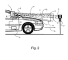
- the imaging sensor 5 of the sensor cluster 1 will, within its field of view, have a fixed vehicle 3 structural part 11, here an edge of the engine hood 11 of the vehicle 3.
- the edge of the engine hood 11 of the vehicle 3 is also within a detection range of the imaging sensor 5 and in the depth-of-field range of the imaging sensor 5 of the sensor cluster 1.
- the aperture of the imaging sensor 5 it is now possible to obtain a measure of the angle which the imaging sensor 5 sees, e.g. from the distance to the reference provided by the edge of the engine hood 11 of the vehicle 3 and the number of pixels between the edge of the engine hood 11 of the vehicle 3 and the border of an acquired image.
- epsilon ⁇ a measure, hereafter called epsilon ⁇ , which measure epsilon ⁇ corresponds to an angle between a center direction 7 of the imaging sensor 5 and a reference provided by a fixed vehicle 3 structural part 11.
- the step of calibrating at least one of the narrow beam sensor 4 and the imaging sensor 5 of the sensor cluster 1 comprises calibrating the center direction 6, 7 of at least one of the narrow beam sensor 4 and the imaging sensor 5 with respect to a geometrical travel axis 10 of the motor vehicle 3 such that the deviation from this axis 10 lies within ⁇ 1°.
- Careful calibration of at least one sensor with respect to the geometrical travel axis 10 of the motor vehicle 3 such that the deviation from this axis lies within ⁇ 1° makes it possible to achieve sufficient alignment of a narrow beam sensor for optimal operation thereof, in particular if it becomes necessary to replace the narrow beam sensor 4 or an associated windshield 2, to which the narrow beam sensor 4 is attached.
- the step of recording the measure epsilon ⁇ comprises recording at least one copy of the measure epsilon ⁇ in a memory unit 8 arranged integral with the sensor cluster 1 and at least one copy of the measure epsilon ⁇ in a memory unit 9 separate from the sensor cluster 1.
- This kind of doubled storage of the measure epsilon ⁇ makes it possible to obtain calibration data when the sensor cluster 1 has to be changed to a spare part. This as it now is possible to obtain this calibration data either from the memory unit 8 of the sensor cluster 1, or should e.g. the memory unit 8 thereof be damaged, from the memory unit 9, which is separate from the sensor cluster.
- a secondary backup memory unit 9 may e.g. be arranged as part of a service database, which may be a cloud based service accessible by service stations, a database kept by the vehicle manufacturer or a database kept by a chain of service stations or similar.
- the step of recording the measure epsilon ⁇ in a memory unit 9 separate from the sensor cluster 1 comprises recording at least one copy of the measure epsilon ⁇ in a memory unit 9 arranged at the specific vehicle 3.
- a secondary backup memory unit 9 at the specific vehicle 3 makes it possible to obtain calibration data for that specific vehicle 3 should the sensor cluster 1 have to be changed to a spare part.
- calibration data may be gathered from the memory unit 9 arranged at the specific vehicle 3.
- the fixed vehicle 3 structural part 11 is an edge of an engine hood of the vehicle 3.
- the measure epsilon ⁇ is based on the edge of the engine hood 11 of the vehicle 3, which edge is a fixed vehicle structural part 11 that is always present in the field of view of the imaging sensor 5, it is possible to have the sensor cluster 1 monitor its calibration state. Hereby it becomes possible to e.g. trigger a fault message to a vehicle operator, should the imaging sensor 5 be unable to detect this fixed vehicle structural part 11.
- the possibility of providing further detection and diagnostic functions for the sensor cluster 1 based on this fact is also envisaged.
- the above method permits autonomous calibration (i.e., independently of a service station) of an onboard sensor cluster 1 using onboard means relying on a calibration object 11 present at the vehicle, relying on which object 11 the sensor cluster 1 of the vehicle 3 is calibratable.
- the calibration object 11 is within the field of vision of the imaging sensor 5 of the sensor cluster 1 at all times. This is accomplished in a particularly simple and advantageous manner by using as a calibration object 11 an edge of the engine hood of the vehicle 3, as illustrated in Fig. 2 .
- the edge of the engine hood 11 of the vehicle 3 is within a detection range of the imaging sensor 5 and in the depth-of-field range of the imaging sensor 5 of the sensor cluster 1.
- Fig. 2 shows the edge of the engine hood 11 of the vehicle 3. Due to the location of the calibration object 11 at the edge of the engine hood of the vehicle 3, no external calibration object is necessary. This yields cost advantages, in the repair shop, and also for the owner of the vehicle 3 because the sensor cluster 1 may, if necessary, be recalibrated at any time without the use of complex external instrument technology. Since the engine hood and the edge 11 thereof is aligned accurately with the vehicle 3 by design, the calibration object 11 already has a precise reference position which facilitates good calibration of the sensor cluster 1.
- the setpoint can be calculated from the recorded measure epsilon ⁇ and the angle ⁇ recorded and stored for the new replacement sensor cluster 1.
- a delta value between the setpoint and the actual position is displayed at a display device (not shown) of the vehicle 3 and service personnel may turn the adjustment screw until the difference is within desired limits, e.g. indicated by a visual and/or audible signal indicating that calibration has been achieved.
- the sensor cluster 1 is mounted on a windscreen 2, where the windscreen 2 needs to be replaced, no special tools are needed nor any special training and experience, for recalibrating the sensor cluster following replacement of the windscreen 2.
- the measure epsilon ⁇ is known by the sensor cluster and stored in the memory unit 8 thereof.
- Angle changes to the chassis of the vehicle 3 caused by the replacement of the windscreen 2 are registered upon powering up the vehicle or turning on the ignition. If the deviation is such that the previously stored measure epsilon ⁇ reaches a limit for the accuracy needed a message is displayed that a re-calibration is required.
- Basic instructions on how to re-calibrate the sensor cluster 1 may be delivered together with the replacement windscreen 2, and re-calibration thereof may be done using a screw driver or similar basic tool.
- a motor vehicle 3 comprising a sensor cluster 1, which at least comprises a narrow beam sensor 4 and an imaging sensor 5, and which sensor cluster 1 has been calibrated in accordance with the above method.
Landscapes
- Engineering & Computer Science (AREA)
- Radar, Positioning & Navigation (AREA)
- Remote Sensing (AREA)
- Physics & Mathematics (AREA)
- General Physics & Mathematics (AREA)
- Computer Networks & Wireless Communication (AREA)
- Electromagnetism (AREA)
- Length Measuring Devices By Optical Means (AREA)
Priority Applications (3)
| Application Number | Priority Date | Filing Date | Title |
|---|---|---|---|
| EP13155637.5A EP2767846B1 (fr) | 2013-02-18 | 2013-02-18 | Procédé d'étalonnage d'un groupe de capteurs dans un véhicule automobile |
| US14/171,949 US8970834B2 (en) | 2013-02-18 | 2014-02-04 | Method for calibrating a sensor cluster in a motor vehicle |
| CN201410046239.2A CN103996183B (zh) | 2013-02-18 | 2014-02-10 | 校准机动车辆中的传感器总成的方法 |
Applications Claiming Priority (1)
| Application Number | Priority Date | Filing Date | Title |
|---|---|---|---|
| EP13155637.5A EP2767846B1 (fr) | 2013-02-18 | 2013-02-18 | Procédé d'étalonnage d'un groupe de capteurs dans un véhicule automobile |
Publications (2)
| Publication Number | Publication Date |
|---|---|
| EP2767846A1 true EP2767846A1 (fr) | 2014-08-20 |
| EP2767846B1 EP2767846B1 (fr) | 2017-01-11 |
Family
ID=47757341
Family Applications (1)
| Application Number | Title | Priority Date | Filing Date |
|---|---|---|---|
| EP13155637.5A Active EP2767846B1 (fr) | 2013-02-18 | 2013-02-18 | Procédé d'étalonnage d'un groupe de capteurs dans un véhicule automobile |
Country Status (3)
| Country | Link |
|---|---|
| US (1) | US8970834B2 (fr) |
| EP (1) | EP2767846B1 (fr) |
| CN (1) | CN103996183B (fr) |
Cited By (6)
| Publication number | Priority date | Publication date | Assignee | Title |
|---|---|---|---|---|
| DE102015209764A1 (de) * | 2015-05-28 | 2016-12-01 | Bayerische Motoren Werke Aktiengesellschaft | Extrinsische Kalibrierung einer Bilderfassungseinrichtung eines Fahrzeugs |
| WO2018182737A1 (fr) | 2017-03-31 | 2018-10-04 | Airbus Group Hq, Inc. | Systèmes et procédés permettant d'étalonner des capteurs de véhicules |
| WO2020010043A1 (fr) | 2018-07-06 | 2020-01-09 | Brain Corporation | Systèmes, procédés et appareils pour étalonner des capteurs montés sur un dispositif |
| SE1950992A1 (en) * | 2019-08-30 | 2021-03-01 | Scania Cv Ab | Method and control arrangement for autonomy enabling infrastructure features |
| EP3971673A1 (fr) * | 2016-03-03 | 2022-03-23 | Uatc, Llc | Système de détection de lumière et de télémétrie par faisceau plan |
| US12092771B2 (en) | 2018-07-06 | 2024-09-17 | Brain Corporation | Systems, methods and apparatuses for calibrating sensors mounted on a device |
Families Citing this family (33)
| Publication number | Priority date | Publication date | Assignee | Title |
|---|---|---|---|---|
| WO2014198629A1 (fr) | 2013-06-13 | 2014-12-18 | Basf Se | Détecteur pour la détection optique d'au moins un objet |
| JP6428270B2 (ja) * | 2014-02-10 | 2018-11-28 | 株式会社デンソー | 軸ずれ検出装置 |
| US10996314B2 (en) | 2015-02-17 | 2021-05-04 | Hunter Engineering Company | Method and apparatus for alignment of vehicle blind spot monitoring sensor |
| JP6527369B2 (ja) * | 2015-03-31 | 2019-06-05 | 株式会社デンソー | 車両制御装置、及び車両制御方法 |
| WO2016179798A1 (fr) * | 2015-05-12 | 2016-11-17 | Bayerische Motoren Werke Aktiengesellschaft | Système et procédé mis en oeuvre par ordinateur pour l'étalonnage d'au moins un capteur |
| JP6321576B2 (ja) * | 2015-05-12 | 2018-05-09 | トヨタ自動車株式会社 | 制限装置及び車両 |
| US10365355B1 (en) | 2016-04-21 | 2019-07-30 | Hunter Engineering Company | Method for collective calibration of multiple vehicle safety system sensors |
| US9952317B2 (en) * | 2016-05-27 | 2018-04-24 | Uber Technologies, Inc. | Vehicle sensor calibration system |
| JP6658413B2 (ja) * | 2016-09-07 | 2020-03-04 | 株式会社デンソー | 物体検出装置 |
| US10262475B2 (en) | 2017-01-19 | 2019-04-16 | Ford Global Technologies, Llc | Vehicle sensor health monitoring |
| US10509120B2 (en) * | 2017-02-16 | 2019-12-17 | GM Global Technology Operations LLC | Lidar-radar relative pose calibration |
| US10401501B2 (en) * | 2017-03-31 | 2019-09-03 | Uber Technologies, Inc. | Autonomous vehicle sensor calibration system |
| US10067897B1 (en) | 2017-05-02 | 2018-09-04 | Bendix Commercial Vehicle Systems Llc | System and method for determining the positions of side collision avoidance sensors on a vehicle |
| CN109211298B (zh) * | 2017-07-04 | 2021-08-17 | 百度在线网络技术(北京)有限公司 | 一种传感器标定方法和装置 |
| US11391826B2 (en) * | 2017-09-27 | 2022-07-19 | Magna Electronics Inc. | Vehicle LIDAR sensor calibration system |
| CN111801546B (zh) * | 2018-02-26 | 2022-04-19 | 罗伯特·博世有限公司 | 车辆传感器校准对准和方法 |
| CN108318870B (zh) * | 2018-03-07 | 2024-01-30 | 深圳市道通科技股份有限公司 | 一种车载雷达标定设备 |
| DE102018208846B4 (de) * | 2018-06-05 | 2021-03-11 | Conti Temic Microelectronic Gmbh | Verfahren zur Kalibrierung einer Sensorbaugruppe |
| US12573091B2 (en) | 2018-06-21 | 2026-03-10 | Mahle Aftermarket Italy S.P.A. | System and method of calibrating an optical sensor mounted on board of a vehicle using a graduated mounting bar |
| DE102018210079A1 (de) * | 2018-06-21 | 2019-12-24 | Robert Bosch Gmbh | Verfahren zum initialen Kalibrieren eines Sensors für ein Fahrerassistenzsystem eines Fahrzeugs |
| ES2941712T3 (es) | 2018-06-21 | 2023-05-25 | Mahle Aftermarket Italy S R L | Sistema y método de calibración de un sensor óptico montado a bordo de un vehículo |
| US11376960B2 (en) * | 2018-09-25 | 2022-07-05 | Aptiv Technologies Limited | Object detection sensor alignment |
| WO2020090041A1 (fr) * | 2018-10-31 | 2020-05-07 | 三菱電機株式会社 | Appareil de détection de défaut d'alignement d'axe optique, appareil de détection d'objet et corps mobile |
| US11313946B2 (en) * | 2018-11-12 | 2022-04-26 | Hunter Engineering Company | Method and apparatus for identification of calibration targets during vehicle radar system service procedures |
| ES3000093T3 (en) * | 2018-12-27 | 2025-02-27 | Bpg Sales And Tech Investments Llc | Mobile vehicular alignment for sensor calibration |
| CN111376841B (zh) * | 2018-12-28 | 2021-09-17 | 北汽福田汽车股份有限公司 | 车道偏离系统的标定方法和装置、及存储介质 |
| JP7099354B2 (ja) * | 2019-02-15 | 2022-07-12 | トヨタ自動車株式会社 | 運転支援装置 |
| US12117569B2 (en) * | 2019-10-15 | 2024-10-15 | Cepton Technologies, Inc. | Dynamic calibration of lidar sensors |
| CN112816949B (zh) * | 2019-11-18 | 2024-04-16 | 商汤集团有限公司 | 传感器的标定方法及装置、存储介质、标定系统 |
| CN111578808B (zh) * | 2020-05-18 | 2021-05-11 | 安徽江淮汽车集团股份有限公司 | 一种前挡倾角检测装置 |
| US20230147480A1 (en) * | 2021-11-10 | 2023-05-11 | Gm Cruise Holdings Llc | Radar-lidar extrinsic calibration in unstructured environments |
| CN114137553B (zh) * | 2022-01-30 | 2022-04-12 | 探维科技(北京)有限公司 | 一种图像融合激光的雷达调光方法及系统 |
| JP2024066886A (ja) * | 2022-11-02 | 2024-05-16 | 京セラ株式会社 | 電子機器、電子機器の制御方法、及びプログラム |
Citations (5)
| Publication number | Priority date | Publication date | Assignee | Title |
|---|---|---|---|---|
| US20020072869A1 (en) * | 1999-12-24 | 2002-06-13 | Christoph Stiller | Method of calibrating a sensor system |
| EP1808711A2 (fr) * | 2006-01-16 | 2007-07-18 | Omron Corporation | Détecteur d'objets |
| US20090033926A1 (en) | 2004-10-13 | 2009-02-05 | Karsten Haug | Device for Calibrating an Image Sensor System in a Motor Vehicle |
| US20120140061A1 (en) * | 2010-12-02 | 2012-06-07 | GM Global Technology Operations LLC | Multi-Object Appearance-Enhanced Fusion of Camera and Range Sensor Data |
| EP2500748A2 (fr) * | 2011-03-18 | 2012-09-19 | Ricoh Company, Ltd. | Appareil de caméra stéréo et procédé d'obtention d'image |
Family Cites Families (6)
| Publication number | Priority date | Publication date | Assignee | Title |
|---|---|---|---|---|
| CN100548769C (zh) * | 2004-12-27 | 2009-10-14 | 株式会社爱德克斯 | 车辆传感器装置及使用车辆传感器装置的车辆稳定系统 |
| EP2212671A4 (fr) * | 2007-11-21 | 2013-11-06 | Volvo Constr Equip Ab | Procédé d'étalonnage de capteurs |
| DE102008042018A1 (de) * | 2008-09-12 | 2010-03-18 | Robert Bosch Gmbh | Verfahren zum Justieren oder Kalibrieren eines Fahrzeugumfeldsensors sowie Fahrzeugumfeldsensor-Justier- oder Kalibrier-Anordnung |
| KR101172240B1 (ko) * | 2010-05-18 | 2012-08-07 | 주식회사 만도 | 센서 및 얼라이먼트 조절 방법 |
| US8983788B2 (en) * | 2010-10-01 | 2015-03-17 | GM Global Technology Operations LLC | System and method of measuring a sensor offset |
| KR101962890B1 (ko) * | 2012-03-02 | 2019-08-01 | 현대모비스 주식회사 | 차량 센서 오프셋 보정 시스템 및 그 방법 |
-
2013
- 2013-02-18 EP EP13155637.5A patent/EP2767846B1/fr active Active
-
2014
- 2014-02-04 US US14/171,949 patent/US8970834B2/en active Active
- 2014-02-10 CN CN201410046239.2A patent/CN103996183B/zh active Active
Patent Citations (5)
| Publication number | Priority date | Publication date | Assignee | Title |
|---|---|---|---|---|
| US20020072869A1 (en) * | 1999-12-24 | 2002-06-13 | Christoph Stiller | Method of calibrating a sensor system |
| US20090033926A1 (en) | 2004-10-13 | 2009-02-05 | Karsten Haug | Device for Calibrating an Image Sensor System in a Motor Vehicle |
| EP1808711A2 (fr) * | 2006-01-16 | 2007-07-18 | Omron Corporation | Détecteur d'objets |
| US20120140061A1 (en) * | 2010-12-02 | 2012-06-07 | GM Global Technology Operations LLC | Multi-Object Appearance-Enhanced Fusion of Camera and Range Sensor Data |
| EP2500748A2 (fr) * | 2011-03-18 | 2012-09-19 | Ricoh Company, Ltd. | Appareil de caméra stéréo et procédé d'obtention d'image |
Cited By (14)
| Publication number | Priority date | Publication date | Assignee | Title |
|---|---|---|---|---|
| DE102015209764A1 (de) * | 2015-05-28 | 2016-12-01 | Bayerische Motoren Werke Aktiengesellschaft | Extrinsische Kalibrierung einer Bilderfassungseinrichtung eines Fahrzeugs |
| EP3971673A1 (fr) * | 2016-03-03 | 2022-03-23 | Uatc, Llc | Système de détection de lumière et de télémétrie par faisceau plan |
| US12105517B2 (en) | 2016-03-03 | 2024-10-01 | Aurora Operations, Inc. | Planar-beam, light detection and ranging system |
| US11604475B2 (en) | 2016-03-03 | 2023-03-14 | Uatc, Llc | Planar-beam, light detection and ranging system |
| EP3600965A4 (fr) * | 2017-03-31 | 2020-10-21 | A^3 by Airbus, LLC | Systèmes et procédés permettant d'étalonner des capteurs de véhicules |
| WO2018182737A1 (fr) | 2017-03-31 | 2018-10-04 | Airbus Group Hq, Inc. | Systèmes et procédés permettant d'étalonner des capteurs de véhicules |
| EP3818341A4 (fr) * | 2018-07-06 | 2022-03-16 | Brain Corporation | Systèmes, procédés et appareils pour étalonner des capteurs montés sur un dispositif |
| WO2020010043A1 (fr) | 2018-07-06 | 2020-01-09 | Brain Corporation | Systèmes, procédés et appareils pour étalonner des capteurs montés sur un dispositif |
| US12050289B2 (en) | 2018-07-06 | 2024-07-30 | Brain Corporation | Systems, methods and apparatuses for calibrating sensors mounted on a device |
| US12092771B2 (en) | 2018-07-06 | 2024-09-17 | Brain Corporation | Systems, methods and apparatuses for calibrating sensors mounted on a device |
| WO2021040604A1 (fr) * | 2019-08-30 | 2021-03-04 | Scania Cv Ab | Procédé et agencement de commande pour caractéristiques d'infrastructure permettant une autonomie |
| SE544256C2 (en) * | 2019-08-30 | 2022-03-15 | Scania Cv Ab | Method and control arrangement for autonomy enabling infrastructure features |
| SE1950992A1 (en) * | 2019-08-30 | 2021-03-01 | Scania Cv Ab | Method and control arrangement for autonomy enabling infrastructure features |
| US12536904B2 (en) | 2019-08-30 | 2026-01-27 | Scania Cv Ab | Method and control arrangement for autonomy enabling infra-structure features |
Also Published As
| Publication number | Publication date |
|---|---|
| CN103996183B (zh) | 2018-05-22 |
| US20140233023A1 (en) | 2014-08-21 |
| US8970834B2 (en) | 2015-03-03 |
| EP2767846B1 (fr) | 2017-01-11 |
| CN103996183A (zh) | 2014-08-20 |
Similar Documents
| Publication | Publication Date | Title |
|---|---|---|
| EP2767846B1 (fr) | Procédé d'étalonnage d'un groupe de capteurs dans un véhicule automobile | |
| US12277730B2 (en) | System and method of calibrating an optical sensor mounted on board of a vehicle | |
| US9170101B2 (en) | Method and apparatus for positioning a vehicle service device relative to a vehicle thrust line | |
| US10996314B2 (en) | Method and apparatus for alignment of vehicle blind spot monitoring sensor | |
| EP3114430B1 (fr) | Procédé d'étalonnage, dispositif d'étalonnage, et produit-programme informatique | |
| EP3621037B1 (fr) | Système et procédé d'étalonnage d'un système avancé d'assistance au conducteur à base de positionnement de véhicule | |
| US20160375829A1 (en) | Display System For Vehicles, In Particular Commercial Vehicles | |
| US20230005183A1 (en) | System and method of calibrating an optical sensor mounted on board of a vehicle | |
| JP7582950B2 (ja) | センサ校正のための可動車両位置合わせ | |
| EP3945300B1 (fr) | Système d'étalonnage d'adas pour étalonner au moins un phare d'un véhicule | |
| JP2011180022A (ja) | ステレオカメラの診断方法、およびステレオカメラの診断装置 | |
| JP2023538351A (ja) | センサ校正のための車両床ターゲット位置合わせ | |
| EP3629056B1 (fr) | Alignement de capteur de détection d'objets | |
| US20220091267A1 (en) | Method for ascertaining an operating parameter for operating a surroundings detection system for a vehicle, and surroundings detection system | |
| CN110568412A (zh) | 用于校准传感器组件的方法 | |
| EP4244100B1 (fr) | Multimodalitäts-fahrzeugeck-sensormodul | |
| CN114623856A (zh) | 多传感器的下线复合标定系统和方法 | |
| US20230314578A1 (en) | Auto-calibrating a target sensor using scene mapping information from a reference sensor | |
| KR102387557B1 (ko) | 카메라 시스템 및 카메라 시스템 작동 방법 | |
| EP4279864B1 (fr) | Procédé d'alignement d'un véhicule sur une cible d'étalonnage adas et système d'étalonnage adas | |
| KR20080055349A (ko) | 차량용 카메라 보정 장치 | |
| CN112051589A (zh) | 用于定向在机动车辆上的车辆传感器和摄像机的调节单元 |
Legal Events
| Date | Code | Title | Description |
|---|---|---|---|
| PUAI | Public reference made under article 153(3) epc to a published international application that has entered the european phase |
Free format text: ORIGINAL CODE: 0009012 |
|
| 17P | Request for examination filed |
Effective date: 20130218 |
|
| AK | Designated contracting states |
Kind code of ref document: A1 Designated state(s): AL AT BE BG CH CY CZ DE DK EE ES FI FR GB GR HR HU IE IS IT LI LT LU LV MC MK MT NL NO PL PT RO RS SE SI SK SM TR |
|
| AX | Request for extension of the european patent |
Extension state: BA ME |
|
| R17P | Request for examination filed (corrected) |
Effective date: 20150220 |
|
| RBV | Designated contracting states (corrected) |
Designated state(s): AL AT BE BG CH CY CZ DE DK EE ES FI FR GB GR HR HU IE IS IT LI LT LU LV MC MK MT NL NO PL PT RO RS SE SI SK SM TR |
|
| GRAP | Despatch of communication of intention to grant a patent |
Free format text: ORIGINAL CODE: EPIDOSNIGR1 |
|
| INTG | Intention to grant announced |
Effective date: 20160916 |
|
| GRAS | Grant fee paid |
Free format text: ORIGINAL CODE: EPIDOSNIGR3 |
|
| GRAA | (expected) grant |
Free format text: ORIGINAL CODE: 0009210 |
|
| AK | Designated contracting states |
Kind code of ref document: B1 Designated state(s): AL AT BE BG CH CY CZ DE DK EE ES FI FR GB GR HR HU IE IS IT LI LT LU LV MC MK MT NL NO PL PT RO RS SE SI SK SM TR |
|
| REG | Reference to a national code |
Ref country code: GB Ref legal event code: FG4D |
|
| REG | Reference to a national code |
Ref country code: CH Ref legal event code: EP |
|
| REG | Reference to a national code |
Ref country code: AT Ref legal event code: REF Ref document number: 861783 Country of ref document: AT Kind code of ref document: T Effective date: 20170115 |
|
| REG | Reference to a national code |
Ref country code: IE Ref legal event code: FG4D |
|
| REG | Reference to a national code |
Ref country code: DE Ref legal event code: R096 Ref document number: 602013016363 Country of ref document: DE |
|
| REG | Reference to a national code |
Ref country code: SE Ref legal event code: TRGR |
|
| REG | Reference to a national code |
Ref country code: LT Ref legal event code: MG4D |
|
| REG | Reference to a national code |
Ref country code: NL Ref legal event code: MP Effective date: 20170111 |
|
| PG25 | Lapsed in a contracting state [announced via postgrant information from national office to epo] |
Ref country code: BE Free format text: LAPSE BECAUSE OF NON-PAYMENT OF DUE FEES Effective date: 20170228 |
|
| REG | Reference to a national code |
Ref country code: AT Ref legal event code: MK05 Ref document number: 861783 Country of ref document: AT Kind code of ref document: T Effective date: 20170111 |
|
| PG25 | Lapsed in a contracting state [announced via postgrant information from national office to epo] |
Ref country code: NL Free format text: LAPSE BECAUSE OF FAILURE TO SUBMIT A TRANSLATION OF THE DESCRIPTION OR TO PAY THE FEE WITHIN THE PRESCRIBED TIME-LIMIT Effective date: 20170111 |
|
| PG25 | Lapsed in a contracting state [announced via postgrant information from national office to epo] |
Ref country code: HR Free format text: LAPSE BECAUSE OF FAILURE TO SUBMIT A TRANSLATION OF THE DESCRIPTION OR TO PAY THE FEE WITHIN THE PRESCRIBED TIME-LIMIT Effective date: 20170111 Ref country code: IS Free format text: LAPSE BECAUSE OF FAILURE TO SUBMIT A TRANSLATION OF THE DESCRIPTION OR TO PAY THE FEE WITHIN THE PRESCRIBED TIME-LIMIT Effective date: 20170511 Ref country code: LT Free format text: LAPSE BECAUSE OF FAILURE TO SUBMIT A TRANSLATION OF THE DESCRIPTION OR TO PAY THE FEE WITHIN THE PRESCRIBED TIME-LIMIT Effective date: 20170111 Ref country code: GR Free format text: LAPSE BECAUSE OF FAILURE TO SUBMIT A TRANSLATION OF THE DESCRIPTION OR TO PAY THE FEE WITHIN THE PRESCRIBED TIME-LIMIT Effective date: 20170412 Ref country code: FI Free format text: LAPSE BECAUSE OF FAILURE TO SUBMIT A TRANSLATION OF THE DESCRIPTION OR TO PAY THE FEE WITHIN THE PRESCRIBED TIME-LIMIT Effective date: 20170111 Ref country code: NO Free format text: LAPSE BECAUSE OF FAILURE TO SUBMIT A TRANSLATION OF THE DESCRIPTION OR TO PAY THE FEE WITHIN THE PRESCRIBED TIME-LIMIT Effective date: 20170411 |
|
| PG25 | Lapsed in a contracting state [announced via postgrant information from national office to epo] |
Ref country code: PL Free format text: LAPSE BECAUSE OF FAILURE TO SUBMIT A TRANSLATION OF THE DESCRIPTION OR TO PAY THE FEE WITHIN THE PRESCRIBED TIME-LIMIT Effective date: 20170111 Ref country code: RS Free format text: LAPSE BECAUSE OF FAILURE TO SUBMIT A TRANSLATION OF THE DESCRIPTION OR TO PAY THE FEE WITHIN THE PRESCRIBED TIME-LIMIT Effective date: 20170111 Ref country code: AT Free format text: LAPSE BECAUSE OF FAILURE TO SUBMIT A TRANSLATION OF THE DESCRIPTION OR TO PAY THE FEE WITHIN THE PRESCRIBED TIME-LIMIT Effective date: 20170111 Ref country code: LV Free format text: LAPSE BECAUSE OF FAILURE TO SUBMIT A TRANSLATION OF THE DESCRIPTION OR TO PAY THE FEE WITHIN THE PRESCRIBED TIME-LIMIT Effective date: 20170111 Ref country code: BG Free format text: LAPSE BECAUSE OF FAILURE TO SUBMIT A TRANSLATION OF THE DESCRIPTION OR TO PAY THE FEE WITHIN THE PRESCRIBED TIME-LIMIT Effective date: 20170411 Ref country code: ES Free format text: LAPSE BECAUSE OF FAILURE TO SUBMIT A TRANSLATION OF THE DESCRIPTION OR TO PAY THE FEE WITHIN THE PRESCRIBED TIME-LIMIT Effective date: 20170111 Ref country code: PT Free format text: LAPSE BECAUSE OF FAILURE TO SUBMIT A TRANSLATION OF THE DESCRIPTION OR TO PAY THE FEE WITHIN THE PRESCRIBED TIME-LIMIT Effective date: 20170511 |
|
| REG | Reference to a national code |
Ref country code: CH Ref legal event code: PL |
|
| REG | Reference to a national code |
Ref country code: DE Ref legal event code: R097 Ref document number: 602013016363 Country of ref document: DE |
|
| PG25 | Lapsed in a contracting state [announced via postgrant information from national office to epo] |
Ref country code: EE Free format text: LAPSE BECAUSE OF FAILURE TO SUBMIT A TRANSLATION OF THE DESCRIPTION OR TO PAY THE FEE WITHIN THE PRESCRIBED TIME-LIMIT Effective date: 20170111 Ref country code: IT Free format text: LAPSE BECAUSE OF FAILURE TO SUBMIT A TRANSLATION OF THE DESCRIPTION OR TO PAY THE FEE WITHIN THE PRESCRIBED TIME-LIMIT Effective date: 20170111 Ref country code: LI Free format text: LAPSE BECAUSE OF NON-PAYMENT OF DUE FEES Effective date: 20170228 Ref country code: CH Free format text: LAPSE BECAUSE OF NON-PAYMENT OF DUE FEES Effective date: 20170228 Ref country code: SK Free format text: LAPSE BECAUSE OF FAILURE TO SUBMIT A TRANSLATION OF THE DESCRIPTION OR TO PAY THE FEE WITHIN THE PRESCRIBED TIME-LIMIT Effective date: 20170111 Ref country code: RO Free format text: LAPSE BECAUSE OF FAILURE TO SUBMIT A TRANSLATION OF THE DESCRIPTION OR TO PAY THE FEE WITHIN THE PRESCRIBED TIME-LIMIT Effective date: 20170111 Ref country code: CZ Free format text: LAPSE BECAUSE OF FAILURE TO SUBMIT A TRANSLATION OF THE DESCRIPTION OR TO PAY THE FEE WITHIN THE PRESCRIBED TIME-LIMIT Effective date: 20170111 |
|
| PLBE | No opposition filed within time limit |
Free format text: ORIGINAL CODE: 0009261 |
|
| STAA | Information on the status of an ep patent application or granted ep patent |
Free format text: STATUS: NO OPPOSITION FILED WITHIN TIME LIMIT |
|
| REG | Reference to a national code |
Ref country code: IE Ref legal event code: MM4A |
|
| PG25 | Lapsed in a contracting state [announced via postgrant information from national office to epo] |
Ref country code: SM Free format text: LAPSE BECAUSE OF FAILURE TO SUBMIT A TRANSLATION OF THE DESCRIPTION OR TO PAY THE FEE WITHIN THE PRESCRIBED TIME-LIMIT Effective date: 20170111 Ref country code: MC Free format text: LAPSE BECAUSE OF FAILURE TO SUBMIT A TRANSLATION OF THE DESCRIPTION OR TO PAY THE FEE WITHIN THE PRESCRIBED TIME-LIMIT Effective date: 20170111 Ref country code: DK Free format text: LAPSE BECAUSE OF FAILURE TO SUBMIT A TRANSLATION OF THE DESCRIPTION OR TO PAY THE FEE WITHIN THE PRESCRIBED TIME-LIMIT Effective date: 20170111 |
|
| REG | Reference to a national code |
Ref country code: FR Ref legal event code: ST Effective date: 20171031 |
|
| 26N | No opposition filed |
Effective date: 20171012 |
|
| PG25 | Lapsed in a contracting state [announced via postgrant information from national office to epo] |
Ref country code: LU Free format text: LAPSE BECAUSE OF NON-PAYMENT OF DUE FEES Effective date: 20170218 |
|
| PG25 | Lapsed in a contracting state [announced via postgrant information from national office to epo] |
Ref country code: FR Free format text: LAPSE BECAUSE OF NON-PAYMENT OF DUE FEES Effective date: 20170313 |
|
| REG | Reference to a national code |
Ref country code: BE Ref legal event code: MM Effective date: 20170228 |
|
| PG25 | Lapsed in a contracting state [announced via postgrant information from national office to epo] |
Ref country code: IE Free format text: LAPSE BECAUSE OF NON-PAYMENT OF DUE FEES Effective date: 20170218 Ref country code: SI Free format text: LAPSE BECAUSE OF FAILURE TO SUBMIT A TRANSLATION OF THE DESCRIPTION OR TO PAY THE FEE WITHIN THE PRESCRIBED TIME-LIMIT Effective date: 20170111 |
|
| PG25 | Lapsed in a contracting state [announced via postgrant information from national office to epo] |
Ref country code: MT Free format text: LAPSE BECAUSE OF NON-PAYMENT OF DUE FEES Effective date: 20170218 |
|
| PG25 | Lapsed in a contracting state [announced via postgrant information from national office to epo] |
Ref country code: HU Free format text: LAPSE BECAUSE OF FAILURE TO SUBMIT A TRANSLATION OF THE DESCRIPTION OR TO PAY THE FEE WITHIN THE PRESCRIBED TIME-LIMIT; INVALID AB INITIO Effective date: 20130218 |
|
| PG25 | Lapsed in a contracting state [announced via postgrant information from national office to epo] |
Ref country code: CY Free format text: LAPSE BECAUSE OF NON-PAYMENT OF DUE FEES Effective date: 20170111 |
|
| PG25 | Lapsed in a contracting state [announced via postgrant information from national office to epo] |
Ref country code: MK Free format text: LAPSE BECAUSE OF FAILURE TO SUBMIT A TRANSLATION OF THE DESCRIPTION OR TO PAY THE FEE WITHIN THE PRESCRIBED TIME-LIMIT Effective date: 20170111 |
|
| PG25 | Lapsed in a contracting state [announced via postgrant information from national office to epo] |
Ref country code: TR Free format text: LAPSE BECAUSE OF FAILURE TO SUBMIT A TRANSLATION OF THE DESCRIPTION OR TO PAY THE FEE WITHIN THE PRESCRIBED TIME-LIMIT Effective date: 20170111 |
|
| PG25 | Lapsed in a contracting state [announced via postgrant information from national office to epo] |
Ref country code: AL Free format text: LAPSE BECAUSE OF FAILURE TO SUBMIT A TRANSLATION OF THE DESCRIPTION OR TO PAY THE FEE WITHIN THE PRESCRIBED TIME-LIMIT Effective date: 20170111 |
|
| PGFP | Annual fee paid to national office [announced via postgrant information from national office to epo] |
Ref country code: SE Payment date: 20210119 Year of fee payment: 9 |
|
| REG | Reference to a national code |
Ref country code: SE Ref legal event code: EUG |
|
| PG25 | Lapsed in a contracting state [announced via postgrant information from national office to epo] |
Ref country code: SE Free format text: LAPSE BECAUSE OF NON-PAYMENT OF DUE FEES Effective date: 20220219 |
|
| P01 | Opt-out of the competence of the unified patent court (upc) registered |
Effective date: 20231212 |
|
| PGFP | Annual fee paid to national office [announced via postgrant information from national office to epo] |
Ref country code: GB Payment date: 20260121 Year of fee payment: 14 |
|
| PGFP | Annual fee paid to national office [announced via postgrant information from national office to epo] |
Ref country code: DE Payment date: 20260121 Year of fee payment: 14 |