EP2767876A2 - Oscillateur atomique, procédé de détection de résonance du piégeage cohérent de population et détecteur magnétique - Google Patents
Oscillateur atomique, procédé de détection de résonance du piégeage cohérent de population et détecteur magnétique Download PDFInfo
- Publication number
- EP2767876A2 EP2767876A2 EP20140154882 EP14154882A EP2767876A2 EP 2767876 A2 EP2767876 A2 EP 2767876A2 EP 20140154882 EP20140154882 EP 20140154882 EP 14154882 A EP14154882 A EP 14154882A EP 2767876 A2 EP2767876 A2 EP 2767876A2
- Authority
- EP
- European Patent Office
- Prior art keywords
- alkali metal
- metal cell
- laser light
- polarizer
- light
- Prior art date
- Legal status (The legal status is an assumption and is not a legal conclusion. Google has not performed a legal analysis and makes no representation as to the accuracy of the status listed.)
- Granted
Links
Images








Classifications
-
- H—ELECTRICITY
- H03—ELECTRONIC CIRCUITRY
- H03L—AUTOMATIC CONTROL, STARTING, SYNCHRONISATION OR STABILISATION OF GENERATORS OF ELECTRONIC OSCILLATIONS OR PULSES
- H03L7/00—Automatic control of frequency or phase; Synchronisation
- H03L7/26—Automatic control of frequency or phase; Synchronisation using energy levels of molecules, atoms, or subatomic particles as a frequency reference
-
- G—PHYSICS
- G01—MEASURING; TESTING
- G01R—MEASURING ELECTRIC VARIABLES; MEASURING MAGNETIC VARIABLES
- G01R33/00—Arrangements or instruments for measuring magnetic variables
- G01R33/20—Arrangements or instruments for measuring magnetic variables involving magnetic resonance
- G01R33/24—Arrangements or instruments for measuring magnetic variables involving magnetic resonance for measuring direction or magnitude of magnetic fields or magnetic flux
- G01R33/26—Arrangements or instruments for measuring magnetic variables involving magnetic resonance for measuring direction or magnitude of magnetic fields or magnetic flux using optical pumping
-
- G—PHYSICS
- G04—HOROLOGY
- G04F—TIME-INTERVAL MEASURING
- G04F5/00—Apparatus for producing preselected time intervals for use as timing standards
- G04F5/14—Apparatus for producing preselected time intervals for use as timing standards using atomic clocks
- G04F5/145—Apparatus for producing preselected time intervals for use as timing standards using atomic clocks using Coherent Population Trapping
-
- H—ELECTRICITY
- H01—ELECTRIC ELEMENTS
- H01S—DEVICES USING THE PROCESS OF LIGHT AMPLIFICATION BY STIMULATED EMISSION OF RADIATION [LASER] TO AMPLIFY OR GENERATE LIGHT; DEVICES USING STIMULATED EMISSION OF ELECTROMAGNETIC RADIATION IN WAVE RANGES OTHER THAN OPTICAL
- H01S3/00—Lasers, i.e. devices using stimulated emission of electromagnetic radiation in the infrared, visible or ultraviolet wave range
- H01S3/10—Controlling the intensity, frequency, phase, polarisation or direction of the emitted radiation, e.g. switching, gating, modulating or demodulating
-
- H—ELECTRICITY
- H03—ELECTRONIC CIRCUITRY
- H03B—GENERATION OF OSCILLATIONS, DIRECTLY OR BY FREQUENCY-CHANGING, BY CIRCUITS EMPLOYING ACTIVE ELEMENTS WHICH OPERATE IN A NON-SWITCHING MANNER; GENERATION OF NOISE BY SUCH CIRCUITS
- H03B17/00—Generation of oscillations using radiation source and detector, e.g. with interposed variable obturator
Definitions
- the disclosures herein generally relate to an atomic oscillator, a method of detecting a CPT (Coherent Population Trapping) resonance and a magnetic sensor.
- CPT Coherent Population Trapping
- An atomic clock (an atomic oscillator) is an extremely accurate clock. Technologies for reducing the size of the atomic clock are being studied.
- the atomic clock is an oscillator based on transition energy of an electron included in an atom of alkali metal or the like. Especially, electron transition energy of an alkali metal atom is found to be quite accurate if the process is not influenced by any disturbance. Accordingly, stability of frequency, which has been improved by more than several orders of magnitude compared with a crystal oscillator, can be obtained.
- an atomic oscillator having a structure of a microwave oscillator of the related art has a large size and requires large amount of electric power.
- a CPT (Coherent Population Trapping) type atomic oscillator provides stability of frequency, precision of which is higher by three orders of magnitude than that of the crystal oscillator of the related art. Furthermore, it is hoped that size and power consumption of the CPT type atomic oscillator can be reduced.
- a prototype of the CPT type atomic oscillator was manufactured in 2007, and products of the CPT type atomic oscillator have been sold by Symmetricom, Inc., U.S.A. since 2011.
- US patent 6993058 discloses a CPT detector and a method for detecting CPT.
- the CPT detector includes a quantum absorber, a polarization analyzer, and a detector.
- the quantum absorber includes a material having first and second low energy states coupled to a common high energy state. Transitions between the first low energy state and the common high energy state and between the second low energy state and the common high energy state are induced by electromagnetic radiation having a predetermined polarization state.
- the polarization analyzer blocks electromagnetic radiation of the predetermined polarization while passing electromagnetic radiation having a polarization state that is orthogonal to the predetermined polarization.
- the polarization analyzer is irradiated with a portion of the generated electromagnetic radiation that has passed through the quantum absorber.
- the detector generates a signal related to the intensity of electromagnetic radiation that leaves the polarization analyzer.
- Japanese Published Patent Application No. 2010-263593 discloses an optical system of an atomic oscillator that regulates an oscillation frequency by using an optical absorption property by one of a double resonance method utilizing light and micro waves and a coherent population trapping (CPT) method utilizing a quantum interference effect produced by two kinds of resonance light.
- CPT coherent population trapping
- the optical system includes a light source emitting the resonance light; a gas cell disposed at an emitting side of the light source, sealing a gaseous metal atom therein and transmitting the resonance light through a metal atom gas; a light detecting unit detecting the transmitted light that is transmitted through the metal atom gas; and a fluorescence blocking unit blocking at least a part of fluorescence, which is emitted from the metal atom gas to the light detecting unit, and disposed between the metal atom gas and the light detecting unit.
- Japanese Patent No. 4801044 discloses a method for modulating an atomic clock signal and a corresponding atomic clock.
- the laser beams (L1, L2) are pulse-modulated in amplitude to illuminate (A) an interactive medium.
- a detection (B) of the current pulse (Sr) and of the pulses (Sr-1 to Sr-p) preceding said current impulsion is performed.
- the pulses are superimposed (C) by linear combination to generate a compensated atomic clock signal (SHC) whereof the spectral width is minimized.
- SHC compensated atomic clock signal
- the invention is applicable to atomic clocks with pulsed interrogation whereof the interactive medium consists of thermal or laser-cooled atoms.
- the atomic oscillation and magnetic sensor represent alternative uses of the common hardware.
- an atomic oscillator includes an alkali metal cell, in which an alkali metal atom is encapsulated; a light source that emits laser light, which enters the alkali metal cell; a light detector that detects light, which has passed through the alkali metal cell; and a polarizer arranged between the alkali metal cell and the light detector.
- a modulation frequency in the light source is controlled, according to a coherent population trapping resonance, which is a light absorption characteristic of a quantum interference effect for two kinds of resonant lights, by modulating the light source to generate sidebands and injecting laser lights with two different wavelengths which are the sidebands into the alkali metal cell, wherein a magnetic field is applied on the alkali metal cell in a direction parallel to a propagating direction of the laser light, the laser light entering the alkali metal cell has a linear polarization, and a direction of polarization of the laser light is not parallel to a direction of polarization of the polarizer.
- a coherent population trapping resonance which is a light absorption characteristic of a quantum interference effect for two kinds of resonant lights
- a magnetic sensor in yet another embodiment, includes an alkali metal cell, in which an alkali metal atom is encapsulated; a light source that emits laser light, which enters the alkali metal cell; a light detector that detects light, which has passed through the alkali metal cell; and a polarizer arranged between the alkali metal cell and the light detector.
- a modulation frequency in the light source is controlled, according to a coherent population trapping resonance, which is a light absorption characteristic of a quantum interference effect for two kinds of resonant lights, by modulating the light source to generate sidebands, and injecting laser lights with two different wavelengths which are the sidebands into the alkali metal cell, wherein the laser light entering the alkali metal cell has a linear polarization, a direction of polarization of the laser light is not parallel to a direction of polarization of the polarizer, and a density of magnetic flux in a direction parallel to a propagating direction of the laser light is detected in response to the coherent population trapping resonance.
- a CPT type atomic oscillator with high stability of frequency a method of detecting a CPT resonance, and a magnetic sensor are provided.
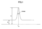
- Fig. 1 is an explanatory diagram illustrating an example of CPT (Coherent Population Trapping) resonance.
- the short-time stability ⁇ y ( ⁇ ) is expressed by formula 1, using the Allan standard deviation, which is used for an index of the stability of frequency.
- ⁇ is an integrated time
- S/N is a signal to noise ratio.
- Q is a resonance Q value in the atomic resonance, and is expressed by formula 2, where f RF represents the RF (radio frequency) frequency and FWHM (full width at half maximum) is a full width of the resonance at half the maximum height, i.e. at the resonance frequency, f RF .
- Q f RF FWHM
- S/N represents a ratio of an intensity of the RF frequency at f RF to noise.
- the ratio S/N is also denoted "contrast Ct" in the following.
- the short-time stability ⁇ y ( ⁇ ) is found to depend on the resonance Q value of the atomic resonance and on the contrast Ct (S/N ratio). That is, by increasing the resonance Q value or the contrast Ct, smaller short-time stability ⁇ y ( ⁇ ) can be obtained, i.e. the frequency becomes stable.
- large resonance amplitude may be obtained by increasing an intensity of laser light for excitation, but at the same time the line width may broaden according to a power broadening effect. Accordingly, in general, increasing the resonance Q value and increasing the contrast Ct (S/N ratio) have a trade-off relationship with each other.
- the stability of the atomic oscillator according to the present embodiment is enhanced by increasing the contrast Ct (S/N ratio), not the resonance Q value.
- the atomic oscillator according to the present embodiment includes a laser light source 110, a collimation lens 120, a first polarizer 131, a second polarizer 132, an alkali metal cell 140, and a light detector 150.
- laser lights with two different sideband wavelengths are generated by modulating the frequency in the laser light source 110, and the laser lights with the sideband wavelengths are injected into the alkali metal cell 140.
- the laser light When the wavelength of the laser light corresponds to excitation energy in the alkali metal atom, the laser light excites the alkali metal atom up to the excited state (resonant light).
- the two resonance lights interfere with each other and a "non-coupled” state is formed by combining the first state and the second state.
- the "non-coupled” state is decoupled from the exited state, i.e.
- the alkali metal atoms are "trapped” in the “non-coupled” state (the “quantum interference effect"), and these atoms do not interact with light (Coherent Population Trapping (CPT) state).
- CPT Coherent Population Trapping
- the wavelengths of the laser lights satisfy the condition for the CPT, the absorption of light by the alkali metal atoms decreases, and a resonance peak appears in the spectrum.
- the modulation frequency for the laser light source 110 is controlled.
- the laser light source 110 is a laser light source for excitation.
- a vertical cavity surface emitting laser (VCSEL) is employed.
- a laser light emitted from the laser light source 110 has a wavelength which is approximately the same as the wavelength of the D 1 line of cesium 133 ( 133 Cs).
- the VCSEL is preferable, since the small-sized VCSEL can emit laser light at low power, and the power consumption of the atomic oscillator can be lowered.
- the alkali metal cell 140 for example, has a shape of a cylinder with a diameter of 22.5 mm and a light path length of 20.0 mm.
- alkali atoms of cesium (Cs) and buffer gas of neon (Ne) are encapsulated.
- An internal pressure of the alkali metal cell 140 is about 4.0 kPa.
- the laser light emitted from the laser light source 110 becomes a laser light with a beam diameter of about 5 mm by passing though the collimation lens 120 and the first polarizer 131, and enters into the alkali metal cell 140.
- the laser light which has passed through the alkali metal cell 140, further passes through the second polarizer 132 and is detected by the light detector 150, which includes a photo diode or the like.
- a lock-in amplifier 161 performs a lock-in detection for the laser light emitted from the laser light source 110, and the electric current, which drives the VCSEL as the laser light source 110, is controlled by the current drive 162 or the like. According to the above control, the wavelength of the laser light emitted from the laser light source 110 is stabilized, so that the light absorbance by the alkali atoms in the alkali metal cell 140 is the maximum. Moreover, the VCSEL as the laser light source 110 is kept at constant temperature.
- a function generator 163 is connected to the rock-in amplifier 161 and the current driver 162.
- a Helmholtz coil (not shown) applies static magnetic field B (for example, 32 ⁇ T) to the alkali metal cell 140.
- the CPT resonance is extracted by using the effect of the Zeeman splitting.
- the alkali metal cell 140 and the Helmholtz coil are covered with a magnetic shield material.
- the alkali metal cell 140 and the Helmholtz coil are set inside a thermostatic bath, so as to keep the temperature constant. In the present embodiment, the temperature of the alkali metal cell 140 is kept between 30 °C and 55 °C.
- the temperature is kept at 42 °C, at which the contrast of the CPT resonance becomes the highest value.
- the magnetic field B means a density of magnetic flux.
- the laser light for the CPT resonance excitation has a linear polarization applied by the first polarizer 131, in order to avoid deviation of the Zeeman sublevel.
- a CPT resonance CPTa in which resonance states
- an output from the light detector 150 is input into the control unit 173, which includes a personal computer (PC) or the like, through the DMM (Digital Multi Meter) 171 and the oscilloscope 172.
- a control signal is sent from the control unit 173 to the analog signal generator 174.
- a cesium primary frequency standard 175 is employed, which is connected to the analog signal generator 174.
- a voltage with a RF (radio frequency) is applied to the VCSEL as the laser light source, and the VCSEL performs frequency modulation (FM).
- FM frequency modulation
- a laser light with the sideband wavelength raised by the frequency modulation is used for the generation of the CPT resonance.
- Fig. 4 is an explanatory diagram illustrating a transmission of the laser light through the alkali metal cell.
- a laser light emitted from the laser light source 110 is injected into the alkali metal cell 140.
- a part of the injected laser light which has a wavelength contributing to the CPT resonance, interacts with the alkali metal in the alkali metal cell 140.
- the laser light which interacts with the alkali metal in the alkali metal cell 140 in this way, is detected as a signal (S) at the light detector 150, such as a photo diode.
- laser light of the injected laser light which has the wavelength contributing to the CPT resonance but does not interact with the alkali metal, and laser light with a wavelength which does not contribute to the CPT resonance, pass through the alkali metal cell 140.
- the laser light which has the wavelength contributing to the CPT resonance but does not interact with the alkali metal, and the laser light with the wavelength which does not contribute to the CPT resonance are detected at the light detector as a noise (N).
- N When the component of laser light detected as a noise is large, the contrast is degraded.
- Fig. 5 shows a relationship between the frequency of the laser light entering the light detector 150 and the light intensity detected by the light detector 150.
- Fig. 6 is an explanatory diagram illustrating the atomic oscillator according to the present embodiment.
- the first polarizer 131 is arranged between the laser light source 110 and the alkali metal cell 140
- the second polarizer 132 is provided between the alkali metal cell 140 and the light detector 150.
- Fig. 7 is another explanatory diagram illustrating the atomic oscillator according to the present embodiment.
- the first polarizer 131 is provided so that a laser light of the injected laser light, having a polarization parallel to the X-axis, transmits.
- the second polarizer 132 is arranged so that a laser light of the injected laser light, having a polarization parallel to the Y-axis. That is, the first polarizer 131 and the second polarizer 132 are arranged, so that the polarization direction of the first polarizer 131 and the polarization of the second polarizer 132 are mutually perpendicular to each other.
- the laser light which has the wavelength contributing to the CPT resonance but does not interact with the alkali metal, and the laser light with the wavelength which does not contribute to the CPT resonance do not pass through the second polarizer 132 and are not detected by the light detector 150, since the polarization direction does not change.
- the laser light which has the wavelength contributing to the CPT resonance but does not interact with the alkali metal, and the laser light with the wavelength which does not contribute to the CPT resonance are not detected by the light detector 150. Accordingly, the noise can be reduced, and the signal-to-noise (SN) ratio can be improved.
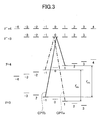
- Fig. 3 is an energy level diagram illustrating the cesium 133 D 1 line data, and shows two CPT resonances, CPTa and CPTb, which are excited by laser light with the linear polarization. That is, when the laser light with the linear polarization is injected into the alkali metal cell 140, the CPT resonance CPTa, shown by dot-dashed lines and the CPT resonance CPTb, shown by solid lines, are excited. A signal, in which two CPT resonances CPTa and CPTb overlap each other, is observed, as shown in Fig. 9. Fig.
- FIG. 9 illustrates a relationship between the density of the magnetic flux applied to the alkali metal cell 140 and the frequency f hfs , which is a frequency difference (hyperfile splitting (hfs)) between two sublevels contributing to each of the CPT resonances, as shown in Fig. 3 .
- the static magnetic field is applied on the alkali metal cell 140 so that the magnetic flux is parallel to the propagation direction of the laser light entering the alkali metal cell 140.
- the density of the magnetic flux is proportional to a difference f a -f b between the frequencies of the two CPT resonances, CPTa and CPTb.
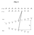
- the density of the magnetic flux applied to the alkali metal cell 140 is preferably more than or equal to 10 ⁇ T. In the case of injecting a laser light with a circular polarization, only one CPT resonance is excited, as shown in Fig. 11 .
- the frequency difference f a -f b of the two CPT resonances is related with the density of magnetic flux B by the relationship expressed by the formula 4.
- the frequency f a is the CPT resonance CPTa, shown by the dot-dashed lines in Fig. 3
- the frequency f b is the CPT resonance CPTb, shown by the solid lines in Fig. 3 .
- f a - f b 4 ⁇ g I ⁇ ⁇ B h ⁇ B
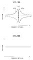
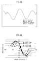
- FIGs. 12A to 14B The Faraday rotational angles for negative density of magnetic flux B, no density, and positive density of magnetic flux B are shown in Figs. 12A and 12B , 13A and 13B , and 14A and 14B , respectively.
- change in the Faraday rotational angle for the CPT resonances CPTa and CPTb cannot be observed.
- Figs. 12A and 12B where the value of the density of magnetic flux is negative, i.e. B ⁇ 0, the Faraday effect on the CPT resonance CPTa and the Faraday effect on the CPT resonance CPTb overlap each other.
- Fig. 12B shows that the change in the Faraday rotational angle for the CPT resonances CPTa and CPTb becomes large at the specific frequency, which can be observed easily.
- Fig. 14A and 14b where the value of the density of magnetic flux is positive, i.e. B>0, the Faraday effect on the CPT resonance CPTa and the Faraday effect on the CPT resonance CPTb overlap each other.
- Fig. 14B shows that the change in the Faraday rotational angle for the CPT resonances CPTa and CPTb becomes large at the specific frequency, which can be observed easily.
- the polarization direction of the first polarizer 131 and the polarization direction of the second polarizer 132 are mutually perpendicular to each other.
- the present invention is not limited to the above, i.e. as long as the polarization directions of the first polarizer 131 and of the second polarizer 132 are different from each other, the same effect as the present embodiment may be obtained.
- only the second polarizer 132 may be arranged without arranging the first polarizer 131.
- the second polarizer 132 is arranged so that the polarization direction of the second polarizer 132 is different from the polarization direction of the laser light emitted from the laser light source 110.
- the polarization direction of the second polarizer 132 is preferably perpendicular to the polarization direction of the laser light emitted from the laser light source 110.
- a measurement apparatus including the same configuration of the atomic oscillator shown in Fig. 2 is prepared, and CPT resonance is measured.
- a vertical cavity surface emitting laser (VCSEL) is used for the laser for excitation as the laser light source 110.
- a wavelength of laser light is the wavelength of the D 1 line of cesium 133, i.e. 895 nm.
- An intensity of the laser light entering the alkali metal cell 140 is 1.1 mW/cm 2 .
- the alkali metal cell 140 has a shape of a cylinder with a diameter of 22.5 mm and a light path length of 20.0 mm.
- alkali metal cell 140 alkali atoms of cesium (Cs) and buffer gas of neon (Ne) are encapsulated.
- An internal pressure of the alkali metal cell 140 is 4 kPa.
- the laser light injected in the alkali metal cell 140 has a beam diameter of 5 mm.
- the laser light having entered the alkali metal cell 140 passes through the alkali metal cell and is detected by the light detector 150, which includes a photo diode or the like.
- the temperature of the VCSEL as the laser light source 110 is kept constant.
- the alkali metal cell 140 and a Helmholtz coil (not shown) are covered with a magnetic shield material. Furthermore, the alkali metal cell 149 and the Helmholtz coil are set inside a thermostatic bath, to keep the temperature constant. Moreover, by applying a current to the Helmholtz coil, a predetermined static magnetic field is applied onto the alkali metal cell 140.
- the temperature of the alkali metal cell is between 39 °C and 55 °C, and is preferably kept at 42 °C, at which the contrast of the CPT resonance becomes the highest value.
- the cesium frequency standard 175 As the reference frequency source for the detectors, the cesium frequency standard 5071A (High performance tube) of Symmetricom, Inc. is employed.
- the first polarizer 131 and the second polarizer 132 polarizers SPFN-30C-26 of Sigma Koki Co. Ltd., Japan, are used.
- a transmission axis (polarization direction) of the first polarizer 131 as the polarizer for excitation, a transmission axis (polarization direction) of the second polarizer 132 as the polarizer for detection, and a laser light axis are arranged as shown in Fig. 15 .
- Fig. 16 shows a result of measurement of the CPT resonance.
- Solid line 16A in Fig. 16 is a result of measurement of the CPT resonance according to the present embodiment, where the first polarizer 131 and the second polarizer 132 are arranged as shown in Fig. 2 .
- Dot-dashed line 16B in Fig. 16 is a result of measurement of the CPT resonance where the first polarizer 131 is arranged but the second polarizer 132 is replaced by a dark filter.
- the static magnetic field of the density of magnetic flux of 94 ⁇ T is applied to the alkali metal cell 140.
- the line width (FWHM) of the CPT resonance and the contrast are found to be 1.15 kHz and 90.1 percent, respectively.
- the positions of the first polarizer 131 and the second polarizer 132 are optimized.
- the static magnetic field of the density of magnetic flux of 5 ⁇ T is applied to the alkali metal cell 140.
- the line width (FMHW) of the CPT resonance and the contrast are found to be 2.32 kHz and 3.3 percent, respectively.
- a result of measurement for the contrast while changing the angle ⁇ of the transmission axis of the second polarizer 132 is shown in Figs. 17 to 19 .
- the angle ⁇ is defined as an angle of the transmission axis of the second polarizer 132 with respect to the direction perpendicular to the transmission axis of the first polarizer 131, as shown in Fig. 15 .
- the static magnetic field of the density of magnetic flux of 30 ⁇ T is applied onto the alkali metal cell 140.
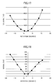
- Fig. 18 illustrates a relationship between the angle ⁇ of the second polarizer 132 and amplitude in the CPT resonance.
- Fig. 18 shows that the component at the wavelength which does not contribute to the CPT resonance is found to be zero.
- the dependence of the amplitude on the angle ⁇ is different from that of the DC current, as shown in Fig. 17 . This is because the polarization angle changes according to the Faraday effect.
- Fig. 19 illustrates a relationship between the angle ⁇ of the second polarizer 132 and the contrast in the CPT resonance, derived from other results.
- the angle q is preferably more than - 15 degrees and less than 15 degrees.
- the direction of the first polarizer 131 is only required to be non-parallel to the direction of the second polarizer 132.
- the first polarizer 131 and the second polarizer 132 are preferably arranged so that the angle between the polarization direction of the second polarizer 132 and the direction perpendicular to the polarization direction of the first polarizer 131 is less than 15 degrees.
- the polarization direction of the component of the wavelength which contributes to the CPT resonance is found to be rotated by the Faraday effect. Furthermore, the contrast is found to be enhanced in the vicinity of the state where the angle ⁇ is zero.
- a result of measurement for the relationship between the static magnetic field and the contrast is shown in Figs. 20 and 21 .
- the angle ⁇ of the second polarizer 132 is set to -3 degrees, where the contrast is the largest, as shown in Fig. 19 .
- Fig. 20 shows the relationship between the static magnetic field and the DC level, and the relationship between the static magnetic field and the resonance amplitude.
- the resonance amplitude of the CPT resonance denoted by “signal” increases linearly with increase in the intensity of the static magnetic field. This is because the frequency difference f a -f b between the two CPT resonances, the CPTa resonance and the CPTb resonance, shown by the dot-dashed lines, and the solid lines respectively, increases, and the overlap of the Faraday effect becomes large.
- the DC level is nearly independent of the intensity of the static magnetic field and shows a constant value.
- Fig. 21 shows the relationship between the static magnetic field and the contrast.
- the contrast is found to become large as the intensity of the static magnetic field increases.
- the density of magnetic flux B is preferably more than 16 ⁇ T.
- Fig. 22 shows a result of measurement for the relationship between the static magnetic field and the line width of the CPT resonance.
- the angle ⁇ of the second polarizer 132 is set to -3 degrees, where the contrast is the largest, as shown in Fig. 19 .
- the line width of the CPT resonance increases approximately linearly with increase in the intensity of the static magnetic field. This is because the frequency difference f a -f b between the two CPT resonances, the CPTa resonance and the CPTb resonance, shown by the dot-dashed lines and the solid lines, respectively, increases, and the line width broadens.
- Fig. 23 shows a result of measurement for the relationship between the static magnetic field and the figure of merit (FOM).
- the figure of merit is defined as the contrast divided by the FWHM, as shown in R. Lutwak, et al., "The Chip-Scale Atomic Clock, Recent Development Progress", Proceedings of the 35th Annual Precise Time and Time Interval (PTTI) Systems and Applications Meeting, December 2-4, 2003, San Diego, CA, USA, pp. 467-478 .
- the density of magnetic flux B is less than 30 ⁇ T
- the figure of merit rises steeply.
- the figure of merit gradually increases.
- the density of magnetic flux B is preferably within the region where B is greater than 30 ⁇ T and less than 60 ⁇ T and the figure of merit has the maximum.
- the alkali metal cell 140 is formed of a glass cell.
- the present embodiment is not limited to this.
- the alkali metal cell 140 may be a MEMS (Micro Electro Mechanical Systems) gas cell, which is formed by forming a through hole in a substrate, such as a silicon (Si) substrate, and by attaching glass substrates on both sides of the substrate.
- MEMS Micro Electro Mechanical Systems
- the atomic oscillator can be miniaturized and the cost can be lowered.
- Cs cesium
- Na sodium
- K potassium
- first polarizer 131 or the second polarizer 132 may be attached on the face of the alkali metal cell 140, through which the laser light passes. Both the first polarized 131 and the second polarized 132 may be attached on the faces of the alkali metal cell 140.
- the alkali metal cell may be heated by the first polarizer 131 or the second polarizer 132.
- the laser light, which does not pass through the first polarizer 131 or the second polarizer 132 is converted into heat.
- a magnetic sensor according to the present embodiment detects a magnetic field by using the characteristics where the line width of the CPT resonance linearly depends on the static magnetic field and the amplitude of the CPT resonance linearly depends on the static magnetic field.
- the CPT type magnetic sensor in the related art measures a frequency difference between a magnetic sublevel, which is highly sensitive to a magnetic field, and another magnetic sublevel, which is insensitive to the magnetic field, and estimates the magnetic field, as shown in P.D.D. Schwindt, "Chip-scale atomic magnetometer", Applied Physics Letters, 85, 6409 (2004 ).
- the frequency difference between the magnetic sublevels becomes large as the magnetic field increases.
- sweeping a wide range of the magnetic field is required, and accuracy and precision of the measurement may be degraded.
- the dependency of the frequency difference between the magnetic sublevel which is the most sensitive to the magnetic field and another magnetic sublevel which is the least sensitive to the magnetic field, on the magnetic field is known to be non-linear.
- the frequency difference is required to be converted to the density of magnetic flux taking account of the non-linearity.
- Fig. 24 shows a diagram illustrating an example of a configuration of the magnetic sensor according to the present embodiment.
- the magnetic sensor includes a laser light source 110, an alkali metal cell 140 and a light detector 150, as in the first embodiment.
- a first polarizer 131 and a second polarizer 132 are arranged between the laser light source 110 and the alkali metal cell 140 and between the alkali metal cell 140 and the light detector 150, respectively.
- the magnetic sensor according to the present embodiment detects a value of the magnetic field in the alkali metal cell 140 as a density of magnetic flux Bs. Different from the atomic oscillator according to the first embodiment, as shown in Fig. 2 , a static magnetic field, by the Helmholtz coil or the like, is not applied on the alkali metal cell 140 according to the present embodiment.
- the magnetic sensor according to the present embodiment detects the value of the density of magnetic flux from the full width at half maximum of the CPT resonance, and thus solves the problem of the related art. That is, the magnetic sensor according to the present embodiment, which measures a full width at the half maximum (FWHM) or an amplitude of one CPT resonance, does not sweep a wide range of frequencies, and can acquire a magnetic field simply and accurately. Moreover, since the FWHM and the amplitude are in principle proportional to the magnetic field, in converting to the magnetic field the non-linearity such as the magnetic sublevels in the related art need not be taken into account. Furthermore, the signal-to-noise (S/N) ratio can be improved.
- FWHM full width at the half maximum
- S/N signal-to-noise
- Fig. 3 is an energy level diagram of the cesium 133 D 1 line data, and illustrates two CPT resonances excited by linear polarization. That is, according to the linear polarization, the CPT resonance CPTa, shown by the dot-dashed lines and the CPT resonance CPTb, shown by the solid lines are excited. A signal, including the two CPT resonances, which overlap each other, is observed. Contributions from CPT resonances by the other levels are separated in the measurement by applying a static magnetic field onto the alkali metal cell 140, since a shift in frequency by the static magnetic field is large for the other magnetic sublevels.
- f a and f b for the density of magnetic flux B, are expressed by formula 6.
- f a , b ⁇ 2 ⁇ g I ⁇ g I ⁇ ⁇ B h ⁇ B + f hfs 2 ⁇ 1 ⁇ g J - g I ⁇ ⁇ B ⁇ B 2 ⁇ h ⁇ f hfs + g J - g I 2 ⁇ ⁇ B 2 ⁇ B 2 h 2 ⁇ f hfs 2 1 / 2 + f hfs 2 ⁇ 1 ⁇ g J - g I ⁇ ⁇ B ⁇ B 2 ⁇ h f hfs + g J - g I 2 ⁇ ⁇ B 2 ⁇ B 2 h 2 ⁇ f hfs 2 1 / 2
- f hfs is the hyperfine splitting frequency, as shown in Fig. 3
- g J is the Landé g-factor.
- the frequency difference between the two levels is derived from the expression in formula 6.
- the frequency difference f a -f b is expressed by formula 7, which is obtained in the approximation up to the order of (g J -g I ) 2 .
- f a - f b 4 ⁇ g I ⁇ ⁇ B h ⁇ B
- the frequency difference is proportional to the density of magnetic flux B, and independent of the frequency f hfs .
- the observed full width at half maximum (FWHM) of the CPT resonance is proportional to the density of magnetic flux B. Accordingly, the density of magnetic flux B can be simply obtained from the FWHM of the CPT resonance. Moreover, the density of magnetic flux B and the FWHM have a linear relationship, as shown by Fig. 22 . Accordingly, if the range of the magnetic field to be measured is wide, the density of magnetic flux B can be measured accurately.
- Fig. 25 shows a result of measurement for the relationship between the density of magnetic flux B and the FWHM. According to the result shown in Fig. 25 , an amount of change in the frequency with respect to the density of magnetic flux is 3.99 Hz/ ⁇ T, and a correlation factor is 0.9936, which shows a quite high linearity between the density of magnetic flux and the FWHM.
- the magnetic sensor according to the present embodiment measures the magnetic field with high precision.
- the resonance amplitude can be used for the magnetic sensor in a certain range of the magnetic field, as the resonance line width (FWHM).
- FWHM resonance line width
- the process of converting measured data into the magnetic field in the present embodiment uses the principle of the Zeeman effect.
- the resonance amplitude is one of the parameters which may vary indirectly, i.e. the resonance amplitude may be affected by the factors other than the magnetic field, such as the intensity of light or the temperature of the gas cell. Accordingly, influences from these factors need be taken into account in measuring the density of magnetic flux.
- the resonance amplitude does not depend on the density of magnetic flux linearly.
- the result of measurement shows that in the extremely strong magnetic field, the resonance amplitude becomes saturated.
- the linearity appears where the density of magnetic flux is outside the region of the strong magnetic field.
- the resonance amplitude can be used for detecting the density of magnetic flux in the weak magnetic field.
- the resonance amplitude can be used for the magnetic sensor, taking the above restrictions into consideration. Moreover, the resonance amplitude and the FWHM can be used in combination for the measurement of the magnetic field.
- FIG. 26 shows a configuration in which the optical intensity modulator 210 is provided between the collimation lens 120 and the first polarizer 131.
- the optical intensity modulator 210 is an optical element that modulates an intensity of the laser light injected into the alkali metal cell 140.
- a light chopper a MEMS (Micro Electro Mechanical Systems) shutter, an acousto-optic modulator, a liquid crystal, or the like may be used.
- MEMS Micro Electro Mechanical Systems
- Fig. 27 shows an atomic oscillator which directly modulates the optical intensity and does not require the optical intensity modulator 210.
- a pulse excitation in order to modulate the optical intensity of the laser light injected into the alkali metal cell 140, a power input to the laser light source 110 is applied to a pulse by a light source driver 220, and a generated optical pulse is injected into the alkali metal cell 140.
- a polarizer method uses the Faraday effect in the CPT.
- the application of high density magnetic flux enlarges the second order Zeeman shift, and may cause a degradation of long term stability of frequency. That is, in the polarizer method, the density of magnetic flux applied to the gas cell is preferably low.
- the pulse excitation and the polarizer method are combined.
- the pulse excitation a power broadening of the CPT resonance is suppressed, a resonance with narrower line width is obtained, and the strength of the magnetic field to be applied can be lowered compared with the case in the continuous excitation.
- a factor that determines the line width of the CPT resonance in the continuous excitation is a natural broadening, the intensity of the injected laser light, a collision broadening depending on a pressure of buffer gas, or uniformity of the magnetic field.
- the line width of the CPT resonance in the continuous excitation is proportional to the intensity of the injected laser light.
- the phenomenon that the line width of the CPT resonance is broadened in proportion to the laser intensity is called a power broadening effect, which is a dominant factor to broaden the line width of the CPT resonance.
- the line width of the CPT resonance obtained by the pulse excitation is known to be independent of the laser intensity.
- the obtained line width depends on the time of the pulse-off (time of free evolution), which is given by Formula 8 as follows.
- FWHM 1 2 ⁇ T
- the line width in the pulse excitation is narrower than that in the continuous excitation.
- ⁇ 0 is a maximum rotational angle of ⁇ a and ⁇ b
- f B is a pulse recurrence frequency, which is a difference between the frequencies f a and f b
- f is a resonance frequency, i.e. an average of f a and f b .
- Fig. 28 illustrates a spectrum of the CPT resonance in the case where the pulse excitation and the polarizer method are combined.
- the pulse recurrence frequency is set to 400 Hz, and the applied density of magnetic flux is 16 ⁇ T.
- an obtained amplitude (signal) of the resonance is 22.35 mV, the DC level is 3.05 mV, which is quite low.
- the contrast is 86%.
- the line width (FWHM) is 170 Hz for the resonance frequency of 4.6 GHz. Since the line width estimated from a pulse recurrence cycle length is 200 Hz, the obtained line width of the CPT resonance is smaller than the theoretical value, where a difference between them is about 20%.
- Fig. 29 illustrates a resonance amplitude in the case where the pulse recurrence frequency is changed for a variety of magnetic fields.
- Each of the resonance amplitudes can be found to have a maximum density of magnetic flux.
- the density of magnetic flux is measured at 7.7 ⁇ T intervals.
- the density of magnetic flux that maximizes the resonance amplitude is 93 ⁇ T.
- the density of magnetic flux becomes 31 ⁇ T, when the pulse recurrence frequency is 1000 Hz, and the density of magnetic flux becomes 16 ⁇ T, when the pulse recurrence frequency is 400 Hz.
- the density of magnetic flux necessary for the pulse excitation is sufficiently low compared with the density of magnetic flux required for the continuous excitation. The results of the measurements are shown in Table 2.
- Fig. 2 shows that as the pulse recurrence frequency becomes smaller, i.e. the pulse cycle length becomes longer, the maximum density of magnetic flux tends to become lower. Moreover, the experimental value is smaller than the theoretical value by about 20%. Since the obtained line width is narrower than the theoretical value by about 20%, the difference between the experimental value and the theoretical value in the density of magnetic flux is considered to be significant.
- the present embodiment relates to a magnetic sensor, a part of the characteristic configuration is the same as that in the third embodiment.
- the polarizer method utilizes the Faraday effect in the CPT.
- the magnetic sensor by the polarizer method according to the present embodiment estimates the applied density of magnetic flux, based on the Zeeman shift between two resonances, from a line width or an amplitude of the obtained resonance.
- a magnetic sensor In general, a magnetic sensor is required to have a high resolution. Moreover, the resolution depends on sensitivity to the magnetic field. Accordingly, in order to enhance the resolution for density of magnetic flux, the sensitivity of the resonance characteristic to the density of magnetic flux is required to be improved.
- the pulse excitation is combined with the polarizer method in the present embodiment.
- the pulse excitation suppresses the power broadening of the CPT resonance, a resonance with narrower line width is obtained, and the change in the resonance amplitude for the density of magnetic flux can be enhanced.
- a factor which determines the line width of the CPT resonance in the continuous excitation is a natural broadening, the intensity of the injected laser light, a collision broadening depending on a pressure of buffer gas, or uniformity of the magnetic field.
- the line width of the CPT resonance in the continuous excitation is proportional to the intensity of the injected laser light.
- the phenomenon in which the line width of the CPT resonance is broadened in proportion to the laser intensity is called a power broadening effect, which is a dominant factor to broaden the line width of the CPT resonance.
- the line width of the CPT resonance obtained by the pulse excitation is known to be independent of the laser intensity.
- the line width in the pulse excitation is narrower than that in the continuous excitation.
- the sensitivity of the polarization rotation ( ⁇ / ⁇ B) to a magnetic field will be calculated, and the characteristics of the resonance in the continuous excitation and in the pulse excitation are compared. Specifically, results of calculation are compared, and it will be confirmed whether the sensitivity of the polarization rotation ( ⁇ / ⁇ B) to the magnetic field in the pulse excitation is better than that in the continuous excitation.
- ⁇ 0 is a maximum rotational angle of ⁇ a and ⁇ b .
- ⁇ a ⁇ b .
- the frequency detuning ⁇ and the Zeeman shift amount f B are normalized by the half width at half maximum ⁇ .
- ⁇ - ⁇ 0 ⁇ 2 ⁇ b ⁇ 1 + b 2 - d 2 1 + b 2 + d 2 2 - 4 ⁇ b 2 ⁇ d 2
- variable "b” the Zeeman shift amount
- b the Zeeman shift amount
- b the Zeeman shift amount
- the sensitivity of the polarization rotation ( ⁇ / ⁇ B) to a magnetic field is expressed by Formula 20.
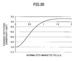
- Fig. 30 illustrates the Faraday rotation angle expressed by Formula 20 in terms of b.
- ⁇ 0 is a maximum rotational angle of ⁇ a and ⁇ b .
- ⁇ a ⁇ b .
- the frequency detuning ⁇ and the Zeeman shift amount f B are normalized by the half width at half maximum ⁇ .
- Formula 29 includes a cosine function, cos( ⁇ b/2), that is, the sensitivity has periodicity.
- ⁇ ⁇ ⁇ B max ⁇ 0 ⁇ 2 ⁇ g I ⁇ ⁇ B ⁇ h ⁇ ⁇
- the sensitivity of the polarization rotation to the magnetic field in the pulse excitation is high. That is, by narrowing the line width according to the pulse excitation, the sensitivity to a density of magnetic flux can be enhanced.
Landscapes
- Physics & Mathematics (AREA)
- General Physics & Mathematics (AREA)
- Condensed Matter Physics & Semiconductors (AREA)
- Electromagnetism (AREA)
- Life Sciences & Earth Sciences (AREA)
- Ecology (AREA)
- Spectroscopy & Molecular Physics (AREA)
- Engineering & Computer Science (AREA)
- Plasma & Fusion (AREA)
- Optics & Photonics (AREA)
- Stabilization Of Oscillater, Synchronisation, Frequency Synthesizers (AREA)
- Investigating Or Analysing Materials By Optical Means (AREA)
Applications Claiming Priority (2)
| Application Number | Priority Date | Filing Date | Title |
|---|---|---|---|
| JP2013026436 | 2013-02-14 | ||
| JP2014006073A JP6346446B2 (ja) | 2013-02-14 | 2014-01-16 | 原子発振器、cpt共鳴の検出方法及び磁気センサ |
Publications (3)
| Publication Number | Publication Date |
|---|---|
| EP2767876A2 true EP2767876A2 (fr) | 2014-08-20 |
| EP2767876A3 EP2767876A3 (fr) | 2018-01-03 |
| EP2767876B1 EP2767876B1 (fr) | 2023-02-08 |
Family
ID=50073009
Family Applications (1)
| Application Number | Title | Priority Date | Filing Date |
|---|---|---|---|
| EP14154882.6A Active EP2767876B1 (fr) | 2013-02-14 | 2014-02-12 | Oscillateur atomique et procédé de détection de résonance cpt |
Country Status (4)
| Country | Link |
|---|---|
| US (2) | US9136851B2 (fr) |
| EP (1) | EP2767876B1 (fr) |
| JP (1) | JP6346446B2 (fr) |
| CN (1) | CN103995458B (fr) |
Cited By (1)
| Publication number | Priority date | Publication date | Assignee | Title |
|---|---|---|---|---|
| CN112904700A (zh) * | 2021-02-04 | 2021-06-04 | 中国科学院国家授时中心 | 一种能够降低激光噪声的pop铷原子钟 |
Families Citing this family (30)
| Publication number | Priority date | Publication date | Assignee | Title |
|---|---|---|---|---|
| US9274186B2 (en) * | 2012-07-06 | 2016-03-01 | The Johns Hopkins University | Gas cell semiconductor chip assembly |
| JP6511734B2 (ja) * | 2014-06-03 | 2019-05-15 | セイコーエプソン株式会社 | 原子セル、量子干渉装置、原子発振器、および電子機器 |
| CN104280023B (zh) * | 2014-10-30 | 2017-06-13 | 成都天奥电子股份有限公司 | 一种相干布局囚禁原子钟和核磁共振原子陀螺仪一体化系统 |
| CN104539289B (zh) * | 2014-11-26 | 2018-04-27 | 江汉大学 | 一种原子频标频率短期稳定度的评估方法和装置 |
| JP6511298B2 (ja) | 2015-03-12 | 2019-05-15 | 株式会社リコー | Cpt共鳴発生方法、cpt共鳴検出方法、cpt共鳴発生装置、原子発振器、磁気センサ |
| EP3112853A1 (fr) * | 2015-07-03 | 2017-01-04 | Memscap S.A. | Appareil pour horloge atomique |
| JP6544132B2 (ja) * | 2015-08-17 | 2019-07-17 | セイコーエプソン株式会社 | 量子干渉装置、原子発振器、および電子機器 |
| JP6575299B2 (ja) * | 2015-10-27 | 2019-09-18 | セイコーエプソン株式会社 | 原子発振器 |
| CN105372981B (zh) * | 2015-12-04 | 2017-10-13 | 兰州空间技术物理研究所 | 一种铯cpt原子钟物理系统 |
| US9733685B2 (en) | 2015-12-14 | 2017-08-15 | International Business Machines Corporation | Temperature-aware microprocessor voltage management |
| US9976955B2 (en) * | 2016-01-06 | 2018-05-22 | Arizona Board Of Regents On Behalf Of Arizona State University | Sub-doppler intermodulated laser-induced-fluorescence spectrometer |
| JP6744658B2 (ja) * | 2016-09-09 | 2020-08-19 | 東京都公立大学法人 | 原子発振器 |
| US10520900B2 (en) * | 2016-12-28 | 2019-12-31 | Texas Instruments Incorporated | Methods and apparatus for magnetically compensated chip scale atomic clock |
| CN106774532B (zh) * | 2016-12-29 | 2019-02-01 | 江汉大学 | 高稳光频输出方法及其控制系统 |
| KR101852338B1 (ko) * | 2017-01-02 | 2018-04-27 | 한국표준과학연구원 | 칩 스케일 원자시계의 물리적 모듈 |
| JP6888235B2 (ja) * | 2017-06-21 | 2021-06-16 | 国立研究開発法人情報通信研究機構 | 原子時計およびそれを用いた磁界強度計 |
| CN107463194B (zh) * | 2017-08-18 | 2020-04-24 | 中国科学院国家授时中心 | 射频信号驱动电热丝加热的温度控制装置 |
| CN107482474A (zh) * | 2017-09-01 | 2017-12-15 | 中恩光电科技(苏州)有限公司 | 一种激光脉冲调制装置 |
| CN107579409B (zh) * | 2017-09-22 | 2019-06-18 | 合肥工业大学 | 一种明亮压缩态光场产生装置 |
| US10684591B1 (en) | 2018-06-27 | 2020-06-16 | The Government Of The United States Of America As Represent By The Secretary Of The Air Force | Optical rubidium atomic frequency standard |
| CN109407157B (zh) * | 2018-12-05 | 2021-04-20 | 中国科学院地质与地球物理研究所 | 一种感应式磁传感器及电磁勘探设备 |
| CN109799468B (zh) * | 2019-03-21 | 2021-07-27 | 中国计量大学 | 一种高精度相干布居囚禁cpt铷原子磁力仪 |
| RU192267U1 (ru) * | 2019-06-28 | 2019-09-11 | Федеральное государственное бюджетное учреждение науки Физический институт им. П.Н. Лебедева Российской академии наук | Устройство контроля и управления генератором ультрастабильных опорных сигналов частоты |
| WO2021049423A1 (fr) | 2019-09-13 | 2021-03-18 | 国立研究開発法人情報通信研究機構 | Résonateur atomique |
| US12092743B2 (en) | 2019-10-04 | 2024-09-17 | Owl Autonomous Imaging, Inc. | System, method, and apparatus for object velocity and acceleration measurement in imaging system |
| CN112304442B (zh) * | 2020-10-28 | 2022-09-02 | 中国科学院国家授时中心 | 双调制cpt差分探测方法及系统 |
| JP7739823B2 (ja) * | 2021-08-02 | 2025-09-17 | 日本電気株式会社 | 量子干渉装置、原子発振器及び制御方法 |
| CN113655701B (zh) * | 2021-09-17 | 2025-05-27 | 波时(北京)科技有限公司 | Cpt原子钟的物理系统 |
| CN116300373A (zh) * | 2023-03-24 | 2023-06-23 | 浙江赛思电子科技有限公司 | 一种cpt原子钟 |
| JP2025149684A (ja) * | 2024-03-26 | 2025-10-08 | ネオアーク株式会社 | 原子発振器及びその動作方法 |
Citations (3)
| Publication number | Priority date | Publication date | Assignee | Title |
|---|---|---|---|---|
| US6993058B2 (en) | 2003-04-28 | 2006-01-31 | Agilent Technologies, Inc. | Coherent population trapping detector |
| JP2010263593A (ja) | 2008-07-03 | 2010-11-18 | Seiko Epson Corp | 原子発振器の光学系及び原子発振器 |
| JP4801044B2 (ja) | 2004-03-30 | 2011-10-26 | サントル ナシオナル ドゥ ラ ルシェルシェサイアンティフィク(セエヌエールエス) | コヒーレント・ポピュレーション・トラッピングにより原子時計信号を変調する方法および対応する原子時計 |
Family Cites Families (20)
| Publication number | Priority date | Publication date | Assignee | Title |
|---|---|---|---|---|
| US3165705A (en) * | 1958-04-30 | 1965-01-12 | Robert H Dicke | Gas cell frequency stabilization |
| US3513381A (en) * | 1967-07-17 | 1970-05-19 | Varian Associates | Off-resonant light as a probe of optically pumped alkali vapors |
| US3740151A (en) * | 1971-08-02 | 1973-06-19 | Hewlett Packard Co | Analyzer employing magneto-optic rotation |
| US7323941B1 (en) * | 2004-02-18 | 2008-01-29 | Princeton University | Method and system for operating a laser self-modulated at alkali-metal atom hyperfine frequency |
| US7102451B2 (en) * | 2004-02-18 | 2006-09-05 | Princeton University, Office Of Technology, Licensing & Intellectual Property | Method and system for operating an atomic clock with alternating-polarization light |
| EP1815588A4 (fr) * | 2004-11-22 | 2010-03-03 | Univ Princeton | Procede et systeme d'exploitation d'un laser auto-module a une frequence hyperfine d'atome de metal alcalin |
| AT505470B1 (de) * | 2007-06-15 | 2010-09-15 | Univ Graz Tech | Verfahren und vorrichtung zum messen von magnetfeldern |
| WO2009073256A2 (fr) * | 2007-09-05 | 2009-06-11 | The Regents Of The Universtiy Of California | Magnétomètre atomique optique |
| JP2009129955A (ja) | 2007-11-20 | 2009-06-11 | Epson Toyocom Corp | 光学系及び原子発振器 |
| US8299858B2 (en) * | 2008-02-07 | 2012-10-30 | Dimension 4 Ltd. | Device, system, and method of frequency generation using an atomic resonator |
| US8237514B2 (en) * | 2009-02-06 | 2012-08-07 | Seiko Epson Corporation | Quantum interference device, atomic oscillator, and magnetic sensor |
| JP5429469B2 (ja) * | 2009-09-07 | 2014-02-26 | セイコーエプソン株式会社 | 量子干渉装置、原子発振器及び磁気センサー |
| CN102377431B (zh) * | 2010-08-06 | 2013-07-31 | 北京大学 | 相干布局数囚禁原子钟及其实现方法 |
| JP5724480B2 (ja) | 2011-03-11 | 2015-05-27 | セイコーエプソン株式会社 | 原子発振器および原子発振器の製造方法 |
| WO2013003859A2 (fr) * | 2011-06-30 | 2013-01-03 | Oewaves, Inc. | Horloges atomiques optiques compactes et applications basées sur une combinaison optique non linéaire paramétrique sur des résonateurs optiques en mode de chuchotement en galerie |
| CN102799101B (zh) * | 2012-02-15 | 2013-09-18 | 中国科学院武汉物理与数学研究所 | 一种芯片cpt原子钟物理系统装置 |
| US9726733B2 (en) * | 2012-02-22 | 2017-08-08 | Geometrics, Inc. | Optical magnetometers |
| WO2013126577A1 (fr) * | 2012-02-22 | 2013-08-29 | Geometrics, Inc. | Dispositif de mesure mécanique quantique |
| CN102629102B (zh) * | 2012-03-26 | 2014-06-04 | 中国科学院武汉物理与数学研究所 | 相干双色光源装置及相干双色光的生成方法 |
| US9575144B2 (en) * | 2012-10-12 | 2017-02-21 | Twinleaf Llc | System and method for atom-modulated, low-drift sensor |
-
2014
- 2014-01-16 JP JP2014006073A patent/JP6346446B2/ja not_active Expired - Fee Related
- 2014-02-10 US US14/176,555 patent/US9136851B2/en active Active
- 2014-02-12 EP EP14154882.6A patent/EP2767876B1/fr active Active
- 2014-02-14 CN CN201410151191.1A patent/CN103995458B/zh not_active Expired - Fee Related
-
2015
- 2015-08-04 US US14/817,605 patent/US9917592B2/en not_active Expired - Fee Related
Patent Citations (3)
| Publication number | Priority date | Publication date | Assignee | Title |
|---|---|---|---|---|
| US6993058B2 (en) | 2003-04-28 | 2006-01-31 | Agilent Technologies, Inc. | Coherent population trapping detector |
| JP4801044B2 (ja) | 2004-03-30 | 2011-10-26 | サントル ナシオナル ドゥ ラ ルシェルシェサイアンティフィク(セエヌエールエス) | コヒーレント・ポピュレーション・トラッピングにより原子時計信号を変調する方法および対応する原子時計 |
| JP2010263593A (ja) | 2008-07-03 | 2010-11-18 | Seiko Epson Corp | 原子発振器の光学系及び原子発振器 |
Non-Patent Citations (4)
| Title |
|---|
| G. KAZAKOV ET AL.: "Pseudoresonance mechanism of all-optical frequency-standard operation", PHYS. REV., vol. A 72, 2005, pages 063408 |
| P.D.D. SCHWINDT: "Chip-scale atomic magnetometer", APPLIED PHYSICS LETTERS, vol. 85, 2004, pages 6409, XP012063954, DOI: doi:10.1063/1.1839274 |
| P.M. ANISIMOV ET AL.: "Influence of transverse magnetic fields and depletion of working levels on the nonlinear resonance Faraday effect", JOURNAL OF EXPERIMENTAL AND THEORETICAL PHYSICS, vol. 97, no. 5, November 2003 (2003-11-01), pages 868 - 874 |
| R. LUTWAK ET AL.: "Proceedings of the 35th Annual Precise Time and Time Interval (PTTI) Systems and Applications Meeting", 2 December 2003, article "The Chip-Scale Atomic Clock, Recent Development Progress", pages: 467 - 478 |
Cited By (1)
| Publication number | Priority date | Publication date | Assignee | Title |
|---|---|---|---|---|
| CN112904700A (zh) * | 2021-02-04 | 2021-06-04 | 中国科学院国家授时中心 | 一种能够降低激光噪声的pop铷原子钟 |
Also Published As
| Publication number | Publication date |
|---|---|
| CN103995458A (zh) | 2014-08-20 |
| US9917592B2 (en) | 2018-03-13 |
| US20140225678A1 (en) | 2014-08-14 |
| JP2014179972A (ja) | 2014-09-25 |
| US9136851B2 (en) | 2015-09-15 |
| CN103995458B (zh) | 2017-06-06 |
| US20150338476A1 (en) | 2015-11-26 |
| EP2767876B1 (fr) | 2023-02-08 |
| JP6346446B2 (ja) | 2018-06-20 |
| EP2767876A3 (fr) | 2018-01-03 |
Similar Documents
| Publication | Publication Date | Title |
|---|---|---|
| EP2767876B1 (fr) | Oscillateur atomique et procédé de détection de résonance cpt | |
| US7825736B2 (en) | Method for suppressing light shift in optical pumping systems | |
| Miletic et al. | AC Stark-shift in CPT-based Cs miniature atomic clocks | |
| US9097750B2 (en) | Dual purpose atomic device for realizing atomic frequency standard and magnetic field measurement | |
| US20150022200A1 (en) | Optically pumped magnetometer and optical pumping magnetic force measuring method | |
| Kozlova et al. | Limitations of long-term stability in a coherent population trapping Cs clock | |
| US20100259256A1 (en) | Apparatus with ambient magnetic field correction | |
| US8154349B2 (en) | Atomic clock regulated by a static field and two oscillating fields | |
| US8183942B2 (en) | Atomic clock operating with helium 3 | |
| Swar et al. | Detection of spin coherence in cold atoms via Faraday rotation fluctuations | |
| US9954544B2 (en) | CPT resonance generation method, CPT resonance detection method, CPT resonance generation apparatus, atomic oscillator and magnetic sensor | |
| Tong et al. | Observation of electric quadrupole transitions to Rydberg nd states of ultracold rubidium atoms | |
| Marx et al. | Precise-and-factor measurements of Ba+ isotopes | |
| Cheng et al. | Ramsey-coherent population trapping Cs atomic clock based on lin∥ lin optical pumping with dispersion detection | |
| US9444476B2 (en) | Atomic oscillator and interrogation method of coherent population trapping resonance | |
| JP6880834B2 (ja) | 磁気センサ、生体磁気測定装置 | |
| Fedorov et al. | Improved measurement of the hyperfine structure of the laser cooling level 4 f 12 (3 H 6) 5 d 5/2 6 s 2 (J= 9/2) in 69 169 Tm | |
| Li et al. | Elliptical polarization of near-resonant linearly polarized probe light in optically pumped alkali metal vapor | |
| Slocum et al. | Nd: LNA laser optical pumping of 4He: Application to space magnetometers | |
| Sargsyan et al. | A modified method of Faraday rotation for investigation of atomic lines of rubidium and potassium in ultrathin cells | |
| Dammalapati | Metastable D-state spectroscopy and laser cooling of barium | |
| Palani et al. | In situ ac Stark shift detection in light storage spectroscopy | |
| Takai et al. | Multistate interferometric measurement of the nonlinear ac Stark shift | |
| Pati et al. | Magnetic Resonance using Synchronous Coherent Population Trapping Spectroscopy | |
| Kaitha et al. | Parametric Study of CPT Resonance in Rubidium Vapor Cell for Application in Atomic Clock. |
Legal Events
| Date | Code | Title | Description |
|---|---|---|---|
| PUAI | Public reference made under article 153(3) epc to a published international application that has entered the european phase |
Free format text: ORIGINAL CODE: 0009012 |
|
| 17P | Request for examination filed |
Effective date: 20140212 |
|
| AK | Designated contracting states |
Kind code of ref document: A2 Designated state(s): AL AT BE BG CH CY CZ DE DK EE ES FI FR GB GR HR HU IE IS IT LI LT LU LV MC MK MT NL NO PL PT RO RS SE SI SK SM TR |
|
| AX | Request for extension of the european patent |
Extension state: BA ME |
|
| PUAL | Search report despatched |
Free format text: ORIGINAL CODE: 0009013 |
|
| AK | Designated contracting states |
Kind code of ref document: A3 Designated state(s): AL AT BE BG CH CY CZ DE DK EE ES FI FR GB GR HR HU IE IS IT LI LT LU LV MC MK MT NL NO PL PT RO RS SE SI SK SM TR |
|
| AX | Request for extension of the european patent |
Extension state: BA ME |
|
| RIC1 | Information provided on ipc code assigned before grant |
Ipc: G04F 5/14 20060101AFI20171129BHEP Ipc: G01R 33/20 20060101ALI20171129BHEP Ipc: H01S 3/10 20060101ALI20171129BHEP Ipc: G01R 33/26 20060101ALI20171129BHEP Ipc: H03L 7/26 20060101ALI20171129BHEP Ipc: H03B 17/00 20060101ALI20171129BHEP |
|
| STAA | Information on the status of an ep patent application or granted ep patent |
Free format text: STATUS: EXAMINATION IS IN PROGRESS |
|
| 17Q | First examination report despatched |
Effective date: 20191111 |
|
| GRAP | Despatch of communication of intention to grant a patent |
Free format text: ORIGINAL CODE: EPIDOSNIGR1 |
|
| STAA | Information on the status of an ep patent application or granted ep patent |
Free format text: STATUS: GRANT OF PATENT IS INTENDED |
|
| INTG | Intention to grant announced |
Effective date: 20220913 |
|
| GRAS | Grant fee paid |
Free format text: ORIGINAL CODE: EPIDOSNIGR3 |
|
| GRAA | (expected) grant |
Free format text: ORIGINAL CODE: 0009210 |
|
| STAA | Information on the status of an ep patent application or granted ep patent |
Free format text: STATUS: THE PATENT HAS BEEN GRANTED |
|
| RAP3 | Party data changed (applicant data changed or rights of an application transferred) |
Owner name: TOKYO METROPOLITAN PUBLIC UNIVERSITY CORPORATION Owner name: RICOH COMPANY, LTD. |
|
| RAP3 | Party data changed (applicant data changed or rights of an application transferred) |
Owner name: TOKYO METROPOLITAN PUBLIC UNIVERSITY CORPORATION Owner name: RICOH COMPANY, LTD. |
|
| AK | Designated contracting states |
Kind code of ref document: B1 Designated state(s): AL AT BE BG CH CY CZ DE DK EE ES FI FR GB GR HR HU IE IS IT LI LT LU LV MC MK MT NL NO PL PT RO RS SE SI SK SM TR |
|
| REG | Reference to a national code |
Ref country code: GB Ref legal event code: FG4D |
|
| REG | Reference to a national code |
Ref country code: CH Ref legal event code: EP Ref country code: AT Ref legal event code: REF Ref document number: 1547604 Country of ref document: AT Kind code of ref document: T Effective date: 20230215 |
|
| REG | Reference to a national code |
Ref country code: IE Ref legal event code: FG4D |
|
| REG | Reference to a national code |
Ref country code: DE Ref legal event code: R096 Ref document number: 602014086206 Country of ref document: DE |
|
| REG | Reference to a national code |
Ref country code: LT Ref legal event code: MG9D |
|
| REG | Reference to a national code |
Ref country code: NL Ref legal event code: MP Effective date: 20230208 |
|
| P01 | Opt-out of the competence of the unified patent court (upc) registered |
Effective date: 20230519 |
|
| REG | Reference to a national code |
Ref country code: AT Ref legal event code: MK05 Ref document number: 1547604 Country of ref document: AT Kind code of ref document: T Effective date: 20230208 |
|
| PG25 | Lapsed in a contracting state [announced via postgrant information from national office to epo] |
Ref country code: RS Free format text: LAPSE BECAUSE OF FAILURE TO SUBMIT A TRANSLATION OF THE DESCRIPTION OR TO PAY THE FEE WITHIN THE PRESCRIBED TIME-LIMIT Effective date: 20230208 Ref country code: PT Free format text: LAPSE BECAUSE OF FAILURE TO SUBMIT A TRANSLATION OF THE DESCRIPTION OR TO PAY THE FEE WITHIN THE PRESCRIBED TIME-LIMIT Effective date: 20230609 Ref country code: NO Free format text: LAPSE BECAUSE OF FAILURE TO SUBMIT A TRANSLATION OF THE DESCRIPTION OR TO PAY THE FEE WITHIN THE PRESCRIBED TIME-LIMIT Effective date: 20230508 Ref country code: NL Free format text: LAPSE BECAUSE OF FAILURE TO SUBMIT A TRANSLATION OF THE DESCRIPTION OR TO PAY THE FEE WITHIN THE PRESCRIBED TIME-LIMIT Effective date: 20230208 Ref country code: LV Free format text: LAPSE BECAUSE OF FAILURE TO SUBMIT A TRANSLATION OF THE DESCRIPTION OR TO PAY THE FEE WITHIN THE PRESCRIBED TIME-LIMIT Effective date: 20230208 Ref country code: LT Free format text: LAPSE BECAUSE OF FAILURE TO SUBMIT A TRANSLATION OF THE DESCRIPTION OR TO PAY THE FEE WITHIN THE PRESCRIBED TIME-LIMIT Effective date: 20230208 Ref country code: HR Free format text: LAPSE BECAUSE OF FAILURE TO SUBMIT A TRANSLATION OF THE DESCRIPTION OR TO PAY THE FEE WITHIN THE PRESCRIBED TIME-LIMIT Effective date: 20230208 Ref country code: ES Free format text: LAPSE BECAUSE OF FAILURE TO SUBMIT A TRANSLATION OF THE DESCRIPTION OR TO PAY THE FEE WITHIN THE PRESCRIBED TIME-LIMIT Effective date: 20230208 Ref country code: AT Free format text: LAPSE BECAUSE OF FAILURE TO SUBMIT A TRANSLATION OF THE DESCRIPTION OR TO PAY THE FEE WITHIN THE PRESCRIBED TIME-LIMIT Effective date: 20230208 |
|
| PG25 | Lapsed in a contracting state [announced via postgrant information from national office to epo] |
Ref country code: SE Free format text: LAPSE BECAUSE OF FAILURE TO SUBMIT A TRANSLATION OF THE DESCRIPTION OR TO PAY THE FEE WITHIN THE PRESCRIBED TIME-LIMIT Effective date: 20230208 Ref country code: PL Free format text: LAPSE BECAUSE OF FAILURE TO SUBMIT A TRANSLATION OF THE DESCRIPTION OR TO PAY THE FEE WITHIN THE PRESCRIBED TIME-LIMIT Effective date: 20230208 Ref country code: IS Free format text: LAPSE BECAUSE OF FAILURE TO SUBMIT A TRANSLATION OF THE DESCRIPTION OR TO PAY THE FEE WITHIN THE PRESCRIBED TIME-LIMIT Effective date: 20230608 Ref country code: GR Free format text: LAPSE BECAUSE OF FAILURE TO SUBMIT A TRANSLATION OF THE DESCRIPTION OR TO PAY THE FEE WITHIN THE PRESCRIBED TIME-LIMIT Effective date: 20230509 Ref country code: FI Free format text: LAPSE BECAUSE OF FAILURE TO SUBMIT A TRANSLATION OF THE DESCRIPTION OR TO PAY THE FEE WITHIN THE PRESCRIBED TIME-LIMIT Effective date: 20230208 |
|
| REG | Reference to a national code |
Ref country code: BE Ref legal event code: MM Effective date: 20230228 |
|
| PG25 | Lapsed in a contracting state [announced via postgrant information from national office to epo] |
Ref country code: SM Free format text: LAPSE BECAUSE OF FAILURE TO SUBMIT A TRANSLATION OF THE DESCRIPTION OR TO PAY THE FEE WITHIN THE PRESCRIBED TIME-LIMIT Effective date: 20230208 Ref country code: RO Free format text: LAPSE BECAUSE OF FAILURE TO SUBMIT A TRANSLATION OF THE DESCRIPTION OR TO PAY THE FEE WITHIN THE PRESCRIBED TIME-LIMIT Effective date: 20230208 Ref country code: LU Free format text: LAPSE BECAUSE OF NON-PAYMENT OF DUE FEES Effective date: 20230212 Ref country code: EE Free format text: LAPSE BECAUSE OF FAILURE TO SUBMIT A TRANSLATION OF THE DESCRIPTION OR TO PAY THE FEE WITHIN THE PRESCRIBED TIME-LIMIT Effective date: 20230208 Ref country code: DK Free format text: LAPSE BECAUSE OF FAILURE TO SUBMIT A TRANSLATION OF THE DESCRIPTION OR TO PAY THE FEE WITHIN THE PRESCRIBED TIME-LIMIT Effective date: 20230208 Ref country code: CZ Free format text: LAPSE BECAUSE OF FAILURE TO SUBMIT A TRANSLATION OF THE DESCRIPTION OR TO PAY THE FEE WITHIN THE PRESCRIBED TIME-LIMIT Effective date: 20230208 |
|
| REG | Reference to a national code |
Ref country code: DE Ref legal event code: R097 Ref document number: 602014086206 Country of ref document: DE |
|
| PG25 | Lapsed in a contracting state [announced via postgrant information from national office to epo] |
Ref country code: SK Free format text: LAPSE BECAUSE OF FAILURE TO SUBMIT A TRANSLATION OF THE DESCRIPTION OR TO PAY THE FEE WITHIN THE PRESCRIBED TIME-LIMIT Effective date: 20230208 |
|
| PLBE | No opposition filed within time limit |
Free format text: ORIGINAL CODE: 0009261 |
|
| STAA | Information on the status of an ep patent application or granted ep patent |
Free format text: STATUS: NO OPPOSITION FILED WITHIN TIME LIMIT |
|
| REG | Reference to a national code |
Ref country code: IE Ref legal event code: MM4A |
|
| 26N | No opposition filed |
Effective date: 20231109 |
|
| PG25 | Lapsed in a contracting state [announced via postgrant information from national office to epo] |
Ref country code: MC Free format text: LAPSE BECAUSE OF FAILURE TO SUBMIT A TRANSLATION OF THE DESCRIPTION OR TO PAY THE FEE WITHIN THE PRESCRIBED TIME-LIMIT Effective date: 20230208 |
|
| PG25 | Lapsed in a contracting state [announced via postgrant information from national office to epo] |
Ref country code: SI Free format text: LAPSE BECAUSE OF FAILURE TO SUBMIT A TRANSLATION OF THE DESCRIPTION OR TO PAY THE FEE WITHIN THE PRESCRIBED TIME-LIMIT Effective date: 20230208 Ref country code: MC Free format text: LAPSE BECAUSE OF FAILURE TO SUBMIT A TRANSLATION OF THE DESCRIPTION OR TO PAY THE FEE WITHIN THE PRESCRIBED TIME-LIMIT Effective date: 20230208 Ref country code: IE Free format text: LAPSE BECAUSE OF NON-PAYMENT OF DUE FEES Effective date: 20230212 |
|
| PG25 | Lapsed in a contracting state [announced via postgrant information from national office to epo] |
Ref country code: BE Free format text: LAPSE BECAUSE OF NON-PAYMENT OF DUE FEES Effective date: 20230228 |
|
| PGFP | Annual fee paid to national office [announced via postgrant information from national office to epo] |
Ref country code: DE Payment date: 20240219 Year of fee payment: 11 Ref country code: GB Payment date: 20240219 Year of fee payment: 11 Ref country code: CH Payment date: 20240301 Year of fee payment: 11 |
|
| PG25 | Lapsed in a contracting state [announced via postgrant information from national office to epo] |
Ref country code: IT Free format text: LAPSE BECAUSE OF FAILURE TO SUBMIT A TRANSLATION OF THE DESCRIPTION OR TO PAY THE FEE WITHIN THE PRESCRIBED TIME-LIMIT Effective date: 20230208 |
|
| PGFP | Annual fee paid to national office [announced via postgrant information from national office to epo] |
Ref country code: FR Payment date: 20240221 Year of fee payment: 11 |
|
| PG25 | Lapsed in a contracting state [announced via postgrant information from national office to epo] |
Ref country code: BG Free format text: LAPSE BECAUSE OF FAILURE TO SUBMIT A TRANSLATION OF THE DESCRIPTION OR TO PAY THE FEE WITHIN THE PRESCRIBED TIME-LIMIT Effective date: 20230208 |
|
| PG25 | Lapsed in a contracting state [announced via postgrant information from national office to epo] |
Ref country code: BG Free format text: LAPSE BECAUSE OF FAILURE TO SUBMIT A TRANSLATION OF THE DESCRIPTION OR TO PAY THE FEE WITHIN THE PRESCRIBED TIME-LIMIT Effective date: 20230208 |
|
| PG25 | Lapsed in a contracting state [announced via postgrant information from national office to epo] |
Ref country code: CY Free format text: LAPSE BECAUSE OF FAILURE TO SUBMIT A TRANSLATION OF THE DESCRIPTION OR TO PAY THE FEE WITHIN THE PRESCRIBED TIME-LIMIT; INVALID AB INITIO Effective date: 20140212 |
|
| PG25 | Lapsed in a contracting state [announced via postgrant information from national office to epo] |
Ref country code: HU Free format text: LAPSE BECAUSE OF FAILURE TO SUBMIT A TRANSLATION OF THE DESCRIPTION OR TO PAY THE FEE WITHIN THE PRESCRIBED TIME-LIMIT; INVALID AB INITIO Effective date: 20140212 |
|
| REG | Reference to a national code |
Ref country code: DE Ref legal event code: R119 Ref document number: 602014086206 Country of ref document: DE |
|
| REG | Reference to a national code |
Ref country code: CH Ref legal event code: PL |
|
| PG25 | Lapsed in a contracting state [announced via postgrant information from national office to epo] |
Ref country code: CH Free format text: LAPSE BECAUSE OF NON-PAYMENT OF DUE FEES Effective date: 20250228 |
|
| GBPC | Gb: european patent ceased through non-payment of renewal fee |
Effective date: 20250212 |
|
| PG25 | Lapsed in a contracting state [announced via postgrant information from national office to epo] |
Ref country code: TR Free format text: LAPSE BECAUSE OF FAILURE TO SUBMIT A TRANSLATION OF THE DESCRIPTION OR TO PAY THE FEE WITHIN THE PRESCRIBED TIME-LIMIT Effective date: 20230208 |
|
| PG25 | Lapsed in a contracting state [announced via postgrant information from national office to epo] |
Ref country code: DE Free format text: LAPSE BECAUSE OF NON-PAYMENT OF DUE FEES Effective date: 20250902 |
|
| PG25 | Lapsed in a contracting state [announced via postgrant information from national office to epo] |
Ref country code: GB Free format text: LAPSE BECAUSE OF NON-PAYMENT OF DUE FEES Effective date: 20250212 |
|
| PG25 | Lapsed in a contracting state [announced via postgrant information from national office to epo] |
Ref country code: FR Free format text: LAPSE BECAUSE OF NON-PAYMENT OF DUE FEES Effective date: 20250228 |