EP2768193B1 - Procédé et appareil permettant de corriger des signaux en phase et en quadrature - Google Patents
Procédé et appareil permettant de corriger des signaux en phase et en quadrature Download PDFInfo
- Publication number
- EP2768193B1 EP2768193B1 EP11867240.1A EP11867240A EP2768193B1 EP 2768193 B1 EP2768193 B1 EP 2768193B1 EP 11867240 A EP11867240 A EP 11867240A EP 2768193 B1 EP2768193 B1 EP 2768193B1
- Authority
- EP
- European Patent Office
- Prior art keywords
- signal
- current
- vector
- frame
- current frame
- Prior art date
- Legal status (The legal status is an assumption and is not a legal conclusion. Google has not performed a legal analysis and makes no representation as to the accuracy of the status listed.)
- Active
Links
Images




Classifications
-
- H—ELECTRICITY
- H04—ELECTRIC COMMUNICATION TECHNIQUE
- H04L—TRANSMISSION OF DIGITAL INFORMATION, e.g. TELEGRAPHIC COMMUNICATION
- H04L27/00—Modulated-carrier systems
- H04L27/32—Carrier systems characterised by combinations of two or more of the types covered by groups H04L27/02, H04L27/10, H04L27/18 or H04L27/26
- H04L27/34—Amplitude- and phase-modulated carrier systems, e.g. quadrature-amplitude modulated carrier systems
- H04L27/38—Demodulator circuits; Receiver circuits
- H04L27/3845—Demodulator circuits; Receiver circuits using non - coherent demodulation, i.e. not using a phase synchronous carrier
- H04L27/3854—Demodulator circuits; Receiver circuits using non - coherent demodulation, i.e. not using a phase synchronous carrier using a non - coherent carrier, including systems with baseband correction for phase or frequency offset
-
- H—ELECTRICITY
- H04—ELECTRIC COMMUNICATION TECHNIQUE
- H04L—TRANSMISSION OF DIGITAL INFORMATION, e.g. TELEGRAPHIC COMMUNICATION
- H04L27/00—Modulated-carrier systems
- H04L27/32—Carrier systems characterised by combinations of two or more of the types covered by groups H04L27/02, H04L27/10, H04L27/18 or H04L27/26
- H04L27/34—Amplitude- and phase-modulated carrier systems, e.g. quadrature-amplitude modulated carrier systems
- H04L27/36—Modulator circuits; Transmitter circuits
- H04L27/362—Modulation using more than one carrier, e.g. with quadrature carriers, separately amplitude modulated
- H04L27/364—Arrangements for overcoming imperfections in the modulator, e.g. quadrature error or unbalanced I and Q levels
-
- H—ELECTRICITY
- H04—ELECTRIC COMMUNICATION TECHNIQUE
- H04L—TRANSMISSION OF DIGITAL INFORMATION, e.g. TELEGRAPHIC COMMUNICATION
- H04L1/00—Arrangements for detecting or preventing errors in the information received
- H04L1/24—Testing correct operation
- H04L1/242—Testing correct operation by comparing a transmitted test signal with a locally generated replica
- H04L1/243—Testing correct operation by comparing a transmitted test signal with a locally generated replica at the transmitter, using a loop-back
-
- H—ELECTRICITY
- H04—ELECTRIC COMMUNICATION TECHNIQUE
- H04L—TRANSMISSION OF DIGITAL INFORMATION, e.g. TELEGRAPHIC COMMUNICATION
- H04L25/00—Baseband systems
- H04L25/02—Details ; arrangements for supplying electrical power along data transmission lines
- H04L25/06—DC level restoring means; Bias distortion correction ; Decision circuits providing symbol by symbol detection
-
- H—ELECTRICITY
- H04—ELECTRIC COMMUNICATION TECHNIQUE
- H04L—TRANSMISSION OF DIGITAL INFORMATION, e.g. TELEGRAPHIC COMMUNICATION
- H04L27/00—Modulated-carrier systems
- H04L27/32—Carrier systems characterised by combinations of two or more of the types covered by groups H04L27/02, H04L27/10, H04L27/18 or H04L27/26
- H04L27/34—Amplitude- and phase-modulated carrier systems, e.g. quadrature-amplitude modulated carrier systems
- H04L27/38—Demodulator circuits; Receiver circuits
- H04L27/3845—Demodulator circuits; Receiver circuits using non - coherent demodulation, i.e. not using a phase synchronous carrier
- H04L27/3854—Demodulator circuits; Receiver circuits using non - coherent demodulation, i.e. not using a phase synchronous carrier using a non - coherent carrier, including systems with baseband correction for phase or frequency offset
- H04L27/3863—Compensation for quadrature error in the received signal
Definitions
- the present invention relates to the field of signal processing, and in particular, to a method and an apparatus for correcting an in-phase signal and a quadrature-phase signal.
- complex signals are generally divided by quadrature sampling into two channels of signals (that is, IQ signals, which may also be written as I/Q signals): I (In-Phase, in-phase) signals and Q (Quadrature-Phase, quadrature-phase) signals.
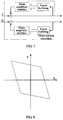
- IQ signals are modulated into a quadrature carrier by using a frequency mixer at a transmit end and then transmitted, as shown in FIG. 1 .
- IQ signals are demodulated and separated by using the quadrature carrier, as shown in FIG. 2 .
- the two channels of signals that is, the IQ signals, have a same amplitude gain and an absolute quadrature phase difference.
- IQ signals do not have a completely same amplitude gain; because a phase shifter is not ideal and a channel phase is distorted non-linearly, phases of IQ signals are not completely quadrature; and IQ signals will have a direct-current offset due to factors such as local oscillator leakage in the system.
- an I signal s I ⁇ and a Q signal s Q ⁇ obtained at a receive end are often distorted coupling of a transmit I signal s I and a transmit Q signal s Q .
- Formulas (1) and (2) show specific relations.
- DC I and DC Q respectively indicate a direct-current offset of an I signal and a direct-current offset of a Q signal
- a I and a Q respectively indicate a gain amplitude of the I signal and a gain amplitude of the Q signal
- ⁇ I and ⁇ Q respectively indicate a phase offset of the I signal and a phase offset of the Q signal.
- Distortion of IQ signals will directly cause distortion of a receive signal constellation diagram, greatly affecting performance of subsequent equalization and demodulation.
- a method of improving circuit component quality and circuit design can reduce a signal distortion degree, this manner will bring an extremely high hardware cost.
- each burst of an OFDM signal which is transmitted, for example, on the basis of the IEEE 802.11a/g WLAN Standard contains a preamble with a sequence of ten short training signals.
- the DC offset is derived from the mean value of the signal over a measurement section of the training signal sequence, with a first subsection of the measurement section in time being weighted with a rising weighting function, and a last subsection of the measurement section in time being weighted with a falling weighting function.
- a central subsection, which is not weighted, may be located between the two.
- the signal is accumulated in this way over the measurement section, and the result is divided by the sum of the weights of the subsections. Using this procedure, the averaging process has better filter characteristics than the noise contribution from the actual signal.
- US 2003/206603 A1 discloses systems and methods for passively calibrating and correct-ing for I/Q mismatch in a quadrature receiver without the necessity of modifying the analog portion of the receiver by adding calibration signals or correction circuitry.
- the passive I/Q mismatch calibration system proceeds using normally received incoming transmitted data signals to obtain statistical information on which to base I/Q mismatch compensation factors.
- the I/Q mismatch compensation factors can be used to adjust the magnitude and phase response in the time domain or the frequency domain, the analog or the digital portion of the receiver.
- the passive I/Q mismatch calibration system can calibrate frequency dependent gain or magnitude imbalance, frequency independent magnitude imbalance, frequency dependent phase imbalance, and frequency independent phase imbalance or combinations or these.
- US 2004/082302 A1 discloses a method and apparatus for removing DC offsets in a ZIF radio device, the method including the steps of converting a signal to digital samples, calculating a
- the system includes a digital DC offset removal circuit, which includes an analog to digital converter, a channel filter connected to the converter, and a rotator system that is connected to the channel filter input and output.
- the rotator system includes a DC estimator connected to the channel filter input, a DC offset removal component connected to the DC estimator, and a rotator connected to the DC offset removal component, the output of the rotator being connected to the channel filter input.
- embodiments of the present invention provide a method and an apparatus for correcting IQ signals.
- the technical solutions are as follows:
- An apparatus for correcting IQ signals including:
- an I signal of a last frame and a Q signal of the last frame are buffered, and direct-current offset elimination and geometric correction are performed for an I signal of a current frame and a Q signal of the current frame according to the I signal of the last frame and the Q signal of the last frame.
- distortion of IQ signals and distortion of an IQ signal constellation diagram can be eliminated to facilitate subsequent signal processing and demodulation without using hardware, thereby greatly lowering a hardware cost.
- this embodiment provides a method for correcting IQ signals.
- the method specifically includes the following steps:
- an I signal of a last frame and a Q signal of the last frame are buffered, and direct-current offset elimination and geometric correction are performed on an I signal of a current frame and a Q signal of the current frame according to the I signal of the last frame and the Q signal of the last frame.
- distortion of IQ signals and distortion of an IQ signal constellation diagram can be eliminated to facilitate subsequent signal processing and demodulation without using hardware, thereby greatly lowering a hardware cost.
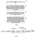
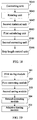
- This embodiment provides a method for correcting an in-phase signal and a quadrature-phase signal. As shown in FIG 4 , IQ signals output by a receiving front end may be corrected by using this method to eliminate distortion.
- a method for correcting an in-phase signal and a quadrature-phase signal is described in detail and specifically includes the following steps:
- the last frame is a segment of continuous signal data prior to a current moment. Its length may be set according to a requirement.
- the eliminating a direct-current offset of the I signal of the current frame and a direct-current offset of the Q signal of the current frame according to the I signal of the last frame and the Q signal of the last frame specifically includes:
- step 202 specifically a direct-current offset DC I of the I signal of the current frame is eliminated according to the direct-current offset of the I signal of the last frame, and a direct-current offset DC Q of the Q signal of the current frame is eliminated according to the direct-current offset of the Q signal of the last frame.
- time length of a frame is specifically 200 to 500 symbols.
- this method further includes:
- M-QAM Multi-Level Quadrature Amplitude Modulation, multi-level quadrature amplitude modulation
- the geometrically correcting an I signal of the current frame after direct-current offset elimination and a Q signal of the current frame after direct-current offset elimination according to the I signal of the last frame and the Q signal of the last frame specifically includes the following steps:
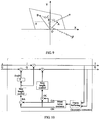
- FIG 8 shows a constellation diagram of the I signal of the last frame after direct-current offset elimination and the Q signal of the last frame after direct-current offset elimination.
- an uncorrected I signal of the last frame after direct-current offset elimination and an uncorrected Q signal of the last frame after direct-current offset elimination are used for description, and the constellation diagram is symmetrical against a base point.
- the third vector OC, the fourth vector BA, and the included angle ⁇ are specifically shown in FIG 9 .
- the third vector OC is a mean vector of the first vector OA and the second vector OB. It is obtained after the sum of the first vector OA and the second vector OB is divided by 2.
- the fourth vector BA is a difference between the first vector OA and the second vector OB.
- the included angle ⁇ reflects overall rotation of the constellation diagram
- an included angle ⁇ between the third vector OC and a Y axis reflects a rotary offset of a Q signal component relative to the Y axis
- reflect relative amplitude distortion between the I signal and the Q signal.
- the geometric correction is specifically determining an IQ unbalanced shape of the I signal of the last frame and the Q signal of the last frame by using two statistical vectors of the I signal of the last frame and the Q signal of the last frame in a signal space, and adjusting gain and rotation of the IQ signals of the current frame in stepping mode by using parameters of the statistical vectors to ultimately obtain balanced IQ signals.
- the geometrically correcting an I signal of the current frame after direct-current offset elimination and a Q signal of the current frame after direct-current offset elimination according to the third vector OC, the fourth vector BA, and the included angle ⁇ includes:
- the included angles ⁇ is the angle between the fourth vector BA and the X axis, and may be obtained by getting an angle of the fourth vector BA.
- step 203-4 the method may further include:
- geometrically corrected IQ signals may be directly sent by using a bypass switch to a subsequent baseband processing module while a judgment feedback loop is cut off.
- the bypass switch may be cut off to activate a subsequent adaptive tracking module and close the judgment feedback loop.
- the revising the corrected I signal of the current frame and the corrected Q signal of the current frame symbol by symbol according to a first-order adaptive filtering structure specifically includes:
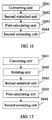
- a manner for revising the corrected I signal of the current frame and the corrected Q signal of the current frame symbol by symbol by using the first-order adaptive filtering structure is implemented by using a logic circuit, as specifically shown in FIG 11 .
- the geometrically corrected I signal s I ⁇ k of the current frame and the geometrically corrected Q signal s Q ⁇ k of the current frame are separately received, and s I ⁇ k and s Q ⁇ k are transmitted on separate branch channels.
- a multiplier is arranged on a first branch channel of s I ⁇ k and s Q ⁇ k .
- s I ⁇ k and s Q ⁇ k are multiplied by corresponding weight coefficients by using the multiplier to obtain a revised I signal s I ( k ) of the current frame and a revised Q signal s Q (k) of the current frame.
- the corrected I signal of the current frame and the corrected Q signal of the current frame are revised symbol by symbol according to the first-order adaptive filtering structure
- the revised I signal of the current frame and the revised Q signal of the current frame are synthesized into a complex signal; and after baseband processing is performed on the complex signal, a demodulator judges the complex signal. Then a judgment result Y is output and fed back.
- the method further includes: revising two weight coefficients C I and C Q according to an error between the corrected complex signal and the judgment result Y fed back by the demodulator, so that the two coefficients change in a gradient direction of decreasing errors to keep approaching and compensate a distortion component in the IQ signals.
- an adaptive algorithm is capable of revising the I signal and the Q signal towards standard distortion-free constellation points with reference to the judgment result Y output and fed back by the demodulator, so as to implement precise compensation; and the symbol-by-symbol revision and update can quickly respond to a real-time change of distortion to better track the distortion.
- a logic circuit shown in FIG 11 for adaptive tracking also provides a manner of adaptively adjusting weight.
- the revised I signal s I ( k ) of the current frame and the revised Q signal s Q ( k ) of the current frame are synthesized into a complex signal S.
- the demodulator judges the complex signal S and then feeds back the judgment result Y.
- the complex signal S and the judgment result Y are adjusted by step length control, respectively access a second branch channel of s I ⁇ k and s Q ⁇ k , and are then operated according to the formula (4) to obtain revised weight coefficients.
- a signal form on an IQ signal input port is two channels of parallel signals, namely, an I signal and a Q signal;
- a signal form on a switch control input port is one channel of binary signals;
- a signal form on a judgment feedback input port is one channel of complex signals;
- a signal form on a bypass IQ signal output port is two channels of parallel signals, namely, an I signal and a Q signal; and
- a signal form on an adaptive correction output port is one channel of complex signals.
- signals of a bypass switch keep being on and only direct-current correction and geometric correction are performed. Corrected IQ signals are output from a bypass port to a subsequent processing module. There is no signal stream on the feedback input port and the adaptive tracking correction output port.
- signals of the bypass switch keep being off and adaptive tracking correction is activated. Corrected complex signals are output from an adaptive tracking correction output port. The complex signals are input to the feedback input port after being judged. There is no signal stream on the bypass output port.
- IQ correction can switch signals of the bypass switch to activate or bypass an adaptive tracking module, depending on whether the modulation mode is high-order or low-order; or keep closing the bypass switch to activate the adaptive tracking module in a long term and reduce switching.
- the method may also be applied in a multiple-input multiple-output (MIMO, Multiple-Input Multiple-Out-put) microwave communication system.
- MIMO multiple-input multiple-output
- the following two manners may be provided for correcting IQ signals in a MIMO system:
- Manner 1 is specifically shown in FIG. 12 .
- Multiple antenna arrays are used at both a transmit end and a receive end to implement point-to-point backhaul communications.
- Multiple channels of signal streams are simultaneously transmitted between transmit and receive antenna arrays in the MIMO system.
- Receiving front ends rely on back-end MIMO decoding to restore data from the multiple channels of signal streams.
- corresponding IQ correcting modules are connected to multiple receiving front ends.
- the number of modulation orders in the system is not very high out of complexity consideration. Therefore, during IQ correction, adaptive tracking correction is bypassed and IQ correction operates in a state without judgment feedback.
- the MIMO system After signals received by the receiving front ends experience the IQ correction, the MIMO system performs decoding and baseband processing. In this manner, an IQ correction method is same as the foregoing embodiment and no further details are provided herein.
- feedback-free states of IQ correcting modules greatly simplify a structure of the MIMO system with IQ correction. This manner enables subsequent baseband processing structures of various channels of IQ signals to be integrated.
- Manner 2 is specifically shown in FIG 13 .
- an auxiliary processing module that helps to generate a feedback signal and a pre-judgment module are added on each branch channel based on FIG 12 .
- Pre-judgment and auxiliary processing are digital processing for a single channel of signals.
- a judgment result provides a reference for correcting IQ signals on a current branch channel. It should be noted that a judgment result of each branch channel provides a reference for correcting IQ signals only on the current branch channel but does not constitute an ultimate decoding result. Ultimate decoding and judgment outputs are generated by a decoding and baseband processing module of the MIMO system.
- each branch channel needs to contain an independent feedback loop; therefore, an auxiliary functional module for generating a feedback signal during baseband processing must be modified, extracted, and separately placed on multiple signal processing branch channels. Feedback not only complicates a system structure but also causes great difficulties in decoding and functional module separation.
- an I signal of a last frame and a Q signal of the last frame are buffered, and direct-current offset elimination and geometric correction are performed on an I signal of a current frame and a Q signal of the current frame according to the I signal of the last frame and the Q signal of the last frame.
- distortion of IQ signals and distortion of an IQ signal constellation diagram can be eliminated to facilitate subsequent signal processing and demodulation without using hardware, thereby greatly lowering a hardware cost.
- this embodiment provides an apparatus for correcting IQ signals.
- the apparatus includes:
- the first correcting module 302 specifically includes:
- the second correcting module 304 specifically includes:
- the second correcting module 304 further includes:
- the second correcting unit 3044 specifically includes:
- the second correcting module 304 further includes:
- the apparatus further includes:
- the adaptive tracking module 305 specifically includes:
- the apparatus further includes:
- the apparatus further includes:
- an I signal of a last frame and a Q signal of the last frame are buffered, and direct-current offset elimination and geometric correction are performed on an I signal of a current frame and a Q signal of the current frame according to the I signal of the last frame and the Q signal of the last frame.
- distortion of IQ signals and distortion of an IQ signal constellation diagram can be eliminated to facilitate subsequent signal processing and demodulation without using hardware, thereby greatly lowering a hardware cost.
- the program may be stored in a computer readable storage medium.
- the storage medium may be a read-only memory, a magnetic disk, an optical disk, or the like.
Landscapes
- Engineering & Computer Science (AREA)
- Computer Networks & Wireless Communication (AREA)
- Signal Processing (AREA)
- Power Engineering (AREA)
- Digital Transmission Methods That Use Modulated Carrier Waves (AREA)
Claims (12)
- Procédé de correction de signaux en phase et en quadrature de phase IQ, comprenantla sauvegarde d'un signal I d'une dernière trame et d'un signal Q de la dernière trame (101) ;la réception d'un signal I d'une trame courante et d'un signal Q de la trame courante ; la mesure statistique d'une valeur de niveau moyen du signal I de la dernière trame pour obtenir un décalage en courant continu du signal I de la dernière trame, et l'élimination d'un décalage en courant continu du signal I de la trame courante en fonction du décalage en courant continu du signal I de la dernière trame ;la mesure statistique d'une valeur de niveau moyen du signal Q de la dernière trame pour obtenir un décalage en courant continu du signal Q de la dernière trame, et l'élimination d'un décalage en courant continu du signal Q de la trame courante en fonction du décalage en courant continu du signal Q de la dernière trame (102), caractérisé par :la sauvegarde d'un signal I de la trame dont le décalage en courant continu est éliminé et d'un signal Q de la trame dont le décalage en courant continu est éliminé (103) ;l'expression, en utilisant un diagramme de constellation, du signal I de la dernière trame dont le décalage en courant continu est éliminé et du signal Q de la dernière trame dont le décalage en courant continu est éliminé ;la mesure statistique de vecteurs moyens dans un premier quart et un second quart du diagramme de constellation du signal I de la trame dont le décalage en courant continu est éliminé et du signal Q de la trame dont le décalage en courant continu est éliminé pour obtenir un premier vecteur et un deuxième vecteur ;le calcul d'un troisième vecteur et d'un quatrième vecteur en fonction du premier vecteur et du deuxième vecteur, et le calcul d'un angle inclus α entre le quatrième vecteur et un axe X, dans lequel le troisième vecteur est un vecteur moyen du premier vecteur et du deuxième vecteur, et le quatrième vecteur est une différence entre le premier vecteur et le deuxième vecteur ; et la correction géométrique du signal I de la trame courante dont le décalage en courant continu est éliminé et du signal Q de la trame courante dont le décalage en courant continu est éliminé en fonction du troisième vecteur, du quatrième vecteur, et de l'angle inclus α pour obtenir le signal I corrigé de la trame courante et le signal Q corrigé de la trame courante (104).
- Procédé selon la revendication 1, comprenant en outre, avant la correction géométrique du signal I de la trame courante dont le décalage en courant continu est éliminé et du signal Q de la trame courante dont le décalage en courant continu est éliminé en fonction du troisième vecteur, du quatrième vecteur, et de l'angle inclus α pour obtenir le signal I corrigé de la trame courante et le signal Q corrigé de la trame courante :la commande de la longueur de pas du troisième vecteur et du quatrième vecteur.
- Procédé selon la revendication 2, comprenant en outre, après l'obtention du signal I corrigé de la trame courante et du signal Q corrigé de la trame courante :la révision du signal I corrigé de la trame courante et du signal Q corrigé de la trame courante symbole par symbole en fonction d'une première structure de filtrage adaptative de premier ordre pour obtenir un signal I révisé de la trame courante et un signal Q révisé de la trame courante, et la synthétisation du signal I révisé de la trame courante et du signal Q révisé de la trame courante en un signal complexe.
- Procédé selon la revendication 3, dans lequel la révision du signal I corrigé de la trame courante et du signal Q corrigé de la trame courante symbole par symbole en fonction d'une première structure de filtrage adaptative de premier ordre comprend spécifiquement :l'exécution d'une compensation de distorsion symbole par symbole sur le signal I corrigé de la trame courante et du signal Q corrigé de la trame courante en utilisant des coefficients de pondération Ci(k) et CQ(k) en fonction d'une première formule qui est spécifiquement :

- Procédé selon la revendication 4, comprenant en outre:la réception, après le jugement du signal final, d'un résultat de jugement produit en sortie après le jugement.
- Procédé selon la revendication 5, comprenant en outre, après la réception d'un résultat de jugement produit en sortie après le jugement :la révision des coefficients de pondération en fonction du signal complexe et du résultat de jugement en utilisant une seconde formule qui est spécifiquement la suivante :

- Appareil de correction de signaux en phase et en quadrature de phase IQ, comprenantun premier module de sauvegarde (301), configuré pour sauvegarder un signal I d'une dernière trame et un signal Q de la dernière trame ;un premier module de correction (302), configuré pour recevoir un signal I d'une trame courante et un signal Q de la trame courante, éliminer un décalage en courant continu du signal I de la trame courante en fonction du signal I de la dernière trame sauvegardé par le premier module de sauvegarde, et éliminer un décalage en courant continu du signal Q de la trame courante en fonction du signal Q de la dernière trame sauvegardé par le premier module de sauvegarde ;un second module de sauvegarde (303), configuré pour sauvegarder un signal I de la dernière trame dont le décalage en courant continu est éliminé et un signal Q de la dernière trame dont le décalage en courant continu est éliminé qui sont obtenus par le premier module de correction ;un second module de correction, configuré pour corriger géométriquement un signal I de la trame courante dont le décalage en courant continu est éliminé et un signal Q de la trame courante dont le décalage en courant continu est éliminé en fonction du signal I de la dernière trame dont le décalage en courant continu est éliminé et du signal Q de la dernière trame dont le décalage en courant continu est éliminé qui sont sauvegardés par le second module de sauvegarde pour obtenir un signal I corrigé de la trame courante et un signal Q corrigé de la trame courante ;dans lequel le premier module de correction comprend spécifïquement :une première unité statistique (3021), configurée pour mesurer statistiquement une valeur de niveau moyen du signal I de la dernière trame pour obtenir un décalage en courant continu du signal I de la dernière trame, et éliminer un décalage en courant continu du signal I de la trame courante en fonction du décalage en courant continu du signal 1 de la dernière trame ;une première unité de correction (3022), configurée pour mesurer statistiquement une valeur de niveau moyen du signal Q de la dernière trame pour obtenir un décalage en courant continu du signal Q de la dernière trame, et éliminer un décalage en courant continu du signal Q de la trame courante en fonction du décalage en courant continu du signal Q de la dernière trame ;dans lequel le second module de correction comprend spécifiquement :une unité de conversion (3041), configurée pour exprimer, en utilisant un diagramme de constellation, le signal I de la trame dont le décalage en courant continu est éliminé et le signal Q de la trame dont le décalage en courant continu est éliminé ; une seconde unité statistique (3042), configurée pour mesurer statistiquement des vecteurs moyens dans un premier quart et un second quart du diagramme de constellation du signal I de la trame dont le décalage en courant continu est éliminé et du signal Q de la trame dont le décalage en courant continu est éliminé pour obtenir un premier vecteur et un deuxième vecteur ;une première unité de calcul (3043), configurée pour calculer un troisième vecteur et un quatrième vecteur en fonction du premier vecteur et du deuxième vecteur, et calculer un angle inclus α entre le quatrième vecteur et un axe X, dans lequel le troisième vecteur est un vecteur moyen du premier vecteur et du deuxième vecteur, et le quatrième vecteur est une différence entre le premier vecteur et le second vecteur ; etune seconde unité de correction (3044), configurée pour corriger géométriquement le signal I de la trame courante dont le décalage en courant continu est éliminé et le signal Q de la trame courante dont le décalage en courant continu est éliminé en fonction du troisième vecteur, du quatrième vecteur, et de l'angle inclus α pour obtenir le signal I corrigé de la trame courante et le signal Q corrigé de la trame courante.
- Appareil selon la revendication 7, dans lequel le second module de correction comprend en outre :une unité de commande de longueur de pas, configurée pour commander la longueur de pas du troisième vecteur et du quatrième vecteur avant que la seconde unité de correction corrige géométriquement le signal I de la trame courante dont le décalage en courant continu est éliminé et le signal Q de la trame courante dont le décalage en courant continu est éliminé en fonction du troisième vecteur, du quatrième vecteur, et de l'angle inclus α pour obtenir le signal 1 corrigé de la trame courante et le signal Q corrigé de la trame courante.
- Appareil selon la revendication 7, comprenant en outre :un module de suivi adaptatif, configuré pour réviser, après que le second module de correction obtient le signal I corrigé de la trame courante et le signal Q corrigé de la trame courante, le signal I corrigé de la trame courante et le signal Q corrigé de la trame courante symbole par symbole en fonction d'une première structure de filtrage adaptative de premier ordre pour obtenir un signal I révisé de la trame courante et un signal Q révisé de la trame courante, et synthétiser le signal I révisé de la trame courante et le signal Q révisé de la trame courante en un signal complexe.
- Appareil selon la revendication 9, dans lequel le module de suivi adaptatif comprend spécifiquement :une troisième unité de correction, configurée pour exécuter une compensation de distorsion symbole par symbole sur le signal 1 corrigé de la trame courante et le signal Q corrigé de la trame courante en utilisant des coefficients de pondération CI(k) et CQ(k) en fonction d'une première formule qui est spécifiquement :

une unité de synthétisation, configurée pour synthétiser les signaux IQ révisés en un signal complexe. - Appareil selon la revendication 10, comprenant en outre:un module de réception de résultat de jugement, configuré pour recevoir, après le jugement du signal final, un résultat de jugement produit en sortie après le jugement.
- Appareil selon la revendication 11, comprenant en outre :un module de révision de coefficients de pondération, configuré pour réviser, après que le module de réception de résultat de jugement reçoit le résultat de jugement produit en sortie après le jugement, les coefficients de pondération en fonction du signal complexe et du résultat de jugement en utilisant une seconde formule qui est spécifiquement la suivante :

Applications Claiming Priority (1)
| Application Number | Priority Date | Filing Date | Title |
|---|---|---|---|
| PCT/CN2011/082240 WO2012167555A1 (fr) | 2011-11-15 | 2011-11-15 | Procédé et appareil permettant de corriger des signaux en phase et en quadrature |
Publications (3)
| Publication Number | Publication Date |
|---|---|
| EP2768193A1 EP2768193A1 (fr) | 2014-08-20 |
| EP2768193A4 EP2768193A4 (fr) | 2014-11-12 |
| EP2768193B1 true EP2768193B1 (fr) | 2016-04-06 |
Family
ID=46353970
Family Applications (1)
| Application Number | Title | Priority Date | Filing Date |
|---|---|---|---|
| EP11867240.1A Active EP2768193B1 (fr) | 2011-11-15 | 2011-11-15 | Procédé et appareil permettant de corriger des signaux en phase et en quadrature |
Country Status (4)
| Country | Link |
|---|---|
| US (1) | US9210025B2 (fr) |
| EP (1) | EP2768193B1 (fr) |
| CN (1) | CN102549994B (fr) |
| WO (1) | WO2012167555A1 (fr) |
Cited By (1)
| Publication number | Priority date | Publication date | Assignee | Title |
|---|---|---|---|---|
| EP4343291A4 (fr) * | 2021-12-30 | 2024-11-27 | China National Petroleum Corporation | Procédé et appareil de démodulation en quadrature de phase globale pour données de détection de fibre optique |
Families Citing this family (10)
| Publication number | Priority date | Publication date | Assignee | Title |
|---|---|---|---|---|
| WO2012167555A1 (fr) | 2011-11-15 | 2012-12-13 | 华为技术有限公司 | Procédé et appareil permettant de corriger des signaux en phase et en quadrature |
| EP2871812B1 (fr) | 2012-08-21 | 2016-11-09 | Huawei Technologies Co., Ltd. | Procédé de correction de signal et récepteur correspondant |
| CN103023829B (zh) * | 2012-11-26 | 2016-04-20 | 电信科学技术研究院 | 一种调制精度的估计方法及装置 |
| CN105610762B (zh) * | 2015-12-17 | 2019-06-04 | 中国电子科技集团公司第四十一研究所 | 一种可校准的宽载波正交调制装置 |
| CN105553902B (zh) * | 2015-12-25 | 2018-09-25 | 京信通信系统(中国)有限公司 | 一种i/q不平衡校正的方法及装置 |
| CN105979520B (zh) * | 2016-04-28 | 2019-04-19 | 东南大学 | 一种基于星座轨迹图的i/q偏移量及畸变估计方法 |
| CN106549682B (zh) * | 2016-11-04 | 2018-11-23 | 北京遥测技术研究所 | 一种减小发射信道角度误差的电路 |
| US10541651B2 (en) * | 2017-07-11 | 2020-01-21 | Analog Devices, Inc. | Mixers with improved linearity |
| CN109660482B (zh) * | 2018-11-28 | 2021-08-20 | 珠海市杰理科技股份有限公司 | Iq补偿参数获取方法、装置、计算机设备及存储介质 |
| CN114866390B (zh) * | 2022-04-03 | 2024-04-19 | 东北师范大学 | 一种基于im/dd的光通信高性能信息传输系统 |
Family Cites Families (21)
| Publication number | Priority date | Publication date | Assignee | Title |
|---|---|---|---|---|
| FR2634609B1 (fr) * | 1988-07-22 | 1990-10-05 | Trt Telecom Radio Electr | Dispositif de modulation pour moduler une onde en phase et en amplitude |
| JPH03174851A (ja) * | 1989-09-29 | 1991-07-30 | Matsushita Electric Ind Co Ltd | ディジタル被変調信号復号装置 |
| US5269065A (en) * | 1990-03-20 | 1993-12-14 | Casio Computer Co., Ltd. | Compass including means for displaying constellation data |
| US5305352A (en) * | 1991-10-31 | 1994-04-19 | At&T Bell Laboratories | Coded modulation with unequal error protection |
| GB9211712D0 (en) * | 1992-06-03 | 1992-07-15 | Fujitsu Microelectronics Ltd | Gm digital receive processing |
| US5822371A (en) * | 1997-02-14 | 1998-10-13 | General Datacomm Inc. | Mapper for high data rate signalling |
| US6097776A (en) * | 1998-02-12 | 2000-08-01 | Cirrus Logic, Inc. | Maximum likelihood estimation of symbol offset |
| SE9900289D0 (sv) * | 1999-01-27 | 1999-01-27 | Ericsson Telefon Ab L M | DC estimate method for a homodyne receiver |
| DE10019602A1 (de) * | 2000-04-20 | 2001-10-25 | Soltel Gmbh | Verfahren und Vorrichtung zum Transformieren eines Signals |
| US6388441B1 (en) * | 2000-10-18 | 2002-05-14 | Baker Hughes Incorporated | Method for processing NMR data without phase-alternating-pair (PAP) averaging |
| EP1293059B1 (fr) * | 2001-02-21 | 2004-03-10 | Matsushita Electric Industrial Co., Ltd. | Procede d'arq hybride avec reagencement en constellation unique |
| US7023927B2 (en) * | 2002-04-12 | 2006-04-04 | Texas Instruments Incorporated | Constellation design for PCM upstream modulation |
| US7158586B2 (en) * | 2002-05-03 | 2007-01-02 | Atheros Communications, Inc. | Systems and methods to provide wideband magnitude and phase imbalance calibration and compensation in quadrature receivers |
| US6999537B2 (en) * | 2002-10-25 | 2006-02-14 | Qualcomm Incorporated | Method of removing DC offset for a ZIF-based GSM radio solution with digital frequency correlation |
| DE10331818B3 (de) * | 2003-07-14 | 2005-03-10 | Infineon Technologies Ag | Verfahren zur Schätzung des DC-Offsets eines OFDM-Empfangssignals, Vorrichtung zur Durchführung des Verfahrens, Funkempfänger mit einer solchen Vorrichtung, sowie Verfahren zur Kompensation eines DC-Offsets eines OFDM-Empfangssignals, Vorrichtung zur Durchführung dieses Verfahrens und Funkempfänger mit einer solchen Vorrichtung |
| KR100532285B1 (ko) * | 2003-09-24 | 2005-11-29 | 삼성전자주식회사 | 시분할 다중 통신방식 수신기의 dc 옵셋 제거 장치 |
| JP4381945B2 (ja) * | 2004-09-30 | 2009-12-09 | 株式会社ルネサステクノロジ | 受信機、受信方法及び携帯無線端末 |
| TWI284472B (en) * | 2005-10-12 | 2007-07-21 | Sunplus Technology Co Ltd | Apparatus and method for adaptively correcting I/Q imbalance |
| US8462898B2 (en) | 2008-06-30 | 2013-06-11 | Entropic Communications, Inc. | System and method for blind compensation and correction of transmitter IQ imbalance at the receiver |
| CN102045278B (zh) * | 2010-12-31 | 2013-05-08 | 成都芯通科技股份有限公司 | 一种基带信号预处理方法 |
| WO2012167555A1 (fr) | 2011-11-15 | 2012-12-13 | 华为技术有限公司 | Procédé et appareil permettant de corriger des signaux en phase et en quadrature |
-
2011
- 2011-11-15 WO PCT/CN2011/082240 patent/WO2012167555A1/fr not_active Ceased
- 2011-11-15 EP EP11867240.1A patent/EP2768193B1/fr active Active
- 2011-11-15 CN CN201180002493.7A patent/CN102549994B/zh active Active
-
2014
- 2014-05-15 US US14/279,070 patent/US9210025B2/en active Active
Cited By (1)
| Publication number | Priority date | Publication date | Assignee | Title |
|---|---|---|---|---|
| EP4343291A4 (fr) * | 2021-12-30 | 2024-11-27 | China National Petroleum Corporation | Procédé et appareil de démodulation en quadrature de phase globale pour données de détection de fibre optique |
Also Published As
| Publication number | Publication date |
|---|---|
| EP2768193A4 (fr) | 2014-11-12 |
| EP2768193A1 (fr) | 2014-08-20 |
| CN102549994B (zh) | 2014-03-05 |
| CN102549994A (zh) | 2012-07-04 |
| US20140247912A1 (en) | 2014-09-04 |
| WO2012167555A1 (fr) | 2012-12-13 |
| US9210025B2 (en) | 2015-12-08 |
Similar Documents
| Publication | Publication Date | Title |
|---|---|---|
| US9210025B2 (en) | Method and apparatus for correcting in-phase signal and quadrature-phase signal | |
| US6442217B1 (en) | Digital communication receiver with digital, IF, I-Q balancer | |
| US7653164B2 (en) | Adaptive IQ imbalance correction for multicarrier wireless communication systems | |
| US10056981B2 (en) | High-speed optical communications system | |
| KR102318134B1 (ko) | Iq 불일치 보상 및 보정을 위한 시스템 및 방법 | |
| US8290458B2 (en) | System and method for IQ imbalance estimation using loopback with frequency offset | |
| US11206163B2 (en) | Radio frequency (RF) to digital polar data converter and time-to-digital converter based time domain signal processing receiver | |
| US8867596B2 (en) | Methods and apparatuses of calibrating I/Q mismatch in communication circuit | |
| US7333788B2 (en) | Method for calibrating automatic gain control in wireless devices | |
| CN1719818B (zh) | 一种正交频分复用系统的采样频率偏差跟踪信号处理装置及方法 | |
| US20050238114A1 (en) | Quadrature modulation system | |
| CN103916343A (zh) | 一种用于无线局域网设备的iq不平衡校正方法和装置 | |
| CN1849791B (zh) | 用于多载波无线通信系统的自适应iq不平衡校正 | |
| EP2337294B1 (fr) | Évaluation du déséquilibre de QI pour symboles de pilote non symétriques | |
| Lin et al. | Joint adaptive transmitter/receiver IQ imbalance correction for OFDM systems | |
| CA2781795C (fr) | Emetteur permettant l'etalonnage d'une modulation en phase/quadrature et methodes connexes | |
| CN116708091B (zh) | 基于帧头的收发iq不平衡与多普勒联合估计与校正方法 | |
| CN114143159B (zh) | 接收机跟踪iq失衡校正方法及装置 | |
| KR100489409B1 (ko) | 무선 통신시스템의 송수신기 성능을 개선하기 위한 방법 | |
| Abd Aziz et al. | A Comparative Study of In-phase and Quadrature (IQ) Imbalance Estimation and Compensation Algorithms for OFDM Receivers | |
| Rykaczewski et al. | Decision directed methods of I/Q imbalance compensation in OFDM systems | |
| WO2025013184A1 (fr) | Dispositif de communication sans fil, procédé de communication sans fil, et programme de compensation de signal | |
| Coersmeier et al. | Frequency Selective IQ Phase and IQ Amplitude Imbalance Adjustments for OFDM Direct Conversion Transmitters | |
| WO2025041309A1 (fr) | Système de communication sans fil | |
| HK1138127A (en) | A method for processing communication signal and a system for processing communication signal |
Legal Events
| Date | Code | Title | Description |
|---|---|---|---|
| PUAI | Public reference made under article 153(3) epc to a published international application that has entered the european phase |
Free format text: ORIGINAL CODE: 0009012 |
|
| 17P | Request for examination filed |
Effective date: 20140515 |
|
| AK | Designated contracting states |
Kind code of ref document: A1 Designated state(s): AL AT BE BG CH CY CZ DE DK EE ES FI FR GB GR HR HU IE IS IT LI LT LU LV MC MK MT NL NO PL PT RO RS SE SI SK SM TR |
|
| A4 | Supplementary search report drawn up and despatched |
Effective date: 20141014 |
|
| RIC1 | Information provided on ipc code assigned before grant |
Ipc: H04L 25/06 20060101AFI20141008BHEP Ipc: H04L 27/38 20060101ALI20141008BHEP |
|
| DAX | Request for extension of the european patent (deleted) | ||
| GRAP | Despatch of communication of intention to grant a patent |
Free format text: ORIGINAL CODE: EPIDOSNIGR1 |
|
| INTG | Intention to grant announced |
Effective date: 20151001 |
|
| GRAS | Grant fee paid |
Free format text: ORIGINAL CODE: EPIDOSNIGR3 |
|
| GRAA | (expected) grant |
Free format text: ORIGINAL CODE: 0009210 |
|
| AK | Designated contracting states |
Kind code of ref document: B1 Designated state(s): AL AT BE BG CH CY CZ DE DK EE ES FI FR GB GR HR HU IE IS IT LI LT LU LV MC MK MT NL NO PL PT RO RS SE SI SK SM TR |
|
| REG | Reference to a national code |
Ref country code: GB Ref legal event code: FG4D |
|
| REG | Reference to a national code |
Ref country code: AT Ref legal event code: REF Ref document number: 788861 Country of ref document: AT Kind code of ref document: T Effective date: 20160415 Ref country code: CH Ref legal event code: EP |
|
| REG | Reference to a national code |
Ref country code: IE Ref legal event code: FG4D |
|
| REG | Reference to a national code |
Ref country code: DE Ref legal event code: R096 Ref document number: 602011025160 Country of ref document: DE |
|
| REG | Reference to a national code |
Ref country code: LT Ref legal event code: MG4D Ref country code: NL Ref legal event code: MP Effective date: 20160406 |
|
| REG | Reference to a national code |
Ref country code: AT Ref legal event code: MK05 Ref document number: 788861 Country of ref document: AT Kind code of ref document: T Effective date: 20160406 |
|
| PG25 | Lapsed in a contracting state [announced via postgrant information from national office to epo] |
Ref country code: NL Free format text: LAPSE BECAUSE OF FAILURE TO SUBMIT A TRANSLATION OF THE DESCRIPTION OR TO PAY THE FEE WITHIN THE PRESCRIBED TIME-LIMIT Effective date: 20160406 |
|
| REG | Reference to a national code |
Ref country code: FR Ref legal event code: PLFP Year of fee payment: 6 |
|
| PG25 | Lapsed in a contracting state [announced via postgrant information from national office to epo] |
Ref country code: NO Free format text: LAPSE BECAUSE OF FAILURE TO SUBMIT A TRANSLATION OF THE DESCRIPTION OR TO PAY THE FEE WITHIN THE PRESCRIBED TIME-LIMIT Effective date: 20160706 Ref country code: IS Free format text: LAPSE BECAUSE OF FAILURE TO SUBMIT A TRANSLATION OF THE DESCRIPTION OR TO PAY THE FEE WITHIN THE PRESCRIBED TIME-LIMIT Effective date: 20160806 Ref country code: LT Free format text: LAPSE BECAUSE OF FAILURE TO SUBMIT A TRANSLATION OF THE DESCRIPTION OR TO PAY THE FEE WITHIN THE PRESCRIBED TIME-LIMIT Effective date: 20160406 Ref country code: FI Free format text: LAPSE BECAUSE OF FAILURE TO SUBMIT A TRANSLATION OF THE DESCRIPTION OR TO PAY THE FEE WITHIN THE PRESCRIBED TIME-LIMIT Effective date: 20160406 Ref country code: PL Free format text: LAPSE BECAUSE OF FAILURE TO SUBMIT A TRANSLATION OF THE DESCRIPTION OR TO PAY THE FEE WITHIN THE PRESCRIBED TIME-LIMIT Effective date: 20160406 |
|
| PG25 | Lapsed in a contracting state [announced via postgrant information from national office to epo] |
Ref country code: HR Free format text: LAPSE BECAUSE OF FAILURE TO SUBMIT A TRANSLATION OF THE DESCRIPTION OR TO PAY THE FEE WITHIN THE PRESCRIBED TIME-LIMIT Effective date: 20160406 Ref country code: GR Free format text: LAPSE BECAUSE OF FAILURE TO SUBMIT A TRANSLATION OF THE DESCRIPTION OR TO PAY THE FEE WITHIN THE PRESCRIBED TIME-LIMIT Effective date: 20160707 Ref country code: SE Free format text: LAPSE BECAUSE OF FAILURE TO SUBMIT A TRANSLATION OF THE DESCRIPTION OR TO PAY THE FEE WITHIN THE PRESCRIBED TIME-LIMIT Effective date: 20160406 Ref country code: ES Free format text: LAPSE BECAUSE OF FAILURE TO SUBMIT A TRANSLATION OF THE DESCRIPTION OR TO PAY THE FEE WITHIN THE PRESCRIBED TIME-LIMIT Effective date: 20160406 Ref country code: PT Free format text: LAPSE BECAUSE OF FAILURE TO SUBMIT A TRANSLATION OF THE DESCRIPTION OR TO PAY THE FEE WITHIN THE PRESCRIBED TIME-LIMIT Effective date: 20160808 Ref country code: RS Free format text: LAPSE BECAUSE OF FAILURE TO SUBMIT A TRANSLATION OF THE DESCRIPTION OR TO PAY THE FEE WITHIN THE PRESCRIBED TIME-LIMIT Effective date: 20160406 Ref country code: LV Free format text: LAPSE BECAUSE OF FAILURE TO SUBMIT A TRANSLATION OF THE DESCRIPTION OR TO PAY THE FEE WITHIN THE PRESCRIBED TIME-LIMIT Effective date: 20160406 Ref country code: AT Free format text: LAPSE BECAUSE OF FAILURE TO SUBMIT A TRANSLATION OF THE DESCRIPTION OR TO PAY THE FEE WITHIN THE PRESCRIBED TIME-LIMIT Effective date: 20160406 |
|
| PG25 | Lapsed in a contracting state [announced via postgrant information from national office to epo] |
Ref country code: IT Free format text: LAPSE BECAUSE OF FAILURE TO SUBMIT A TRANSLATION OF THE DESCRIPTION OR TO PAY THE FEE WITHIN THE PRESCRIBED TIME-LIMIT Effective date: 20160406 Ref country code: BE Free format text: LAPSE BECAUSE OF FAILURE TO SUBMIT A TRANSLATION OF THE DESCRIPTION OR TO PAY THE FEE WITHIN THE PRESCRIBED TIME-LIMIT Effective date: 20160406 |
|
| REG | Reference to a national code |
Ref country code: DE Ref legal event code: R097 Ref document number: 602011025160 Country of ref document: DE |
|
| PG25 | Lapsed in a contracting state [announced via postgrant information from national office to epo] |
Ref country code: SK Free format text: LAPSE BECAUSE OF FAILURE TO SUBMIT A TRANSLATION OF THE DESCRIPTION OR TO PAY THE FEE WITHIN THE PRESCRIBED TIME-LIMIT Effective date: 20160406 Ref country code: EE Free format text: LAPSE BECAUSE OF FAILURE TO SUBMIT A TRANSLATION OF THE DESCRIPTION OR TO PAY THE FEE WITHIN THE PRESCRIBED TIME-LIMIT Effective date: 20160406 Ref country code: CZ Free format text: LAPSE BECAUSE OF FAILURE TO SUBMIT A TRANSLATION OF THE DESCRIPTION OR TO PAY THE FEE WITHIN THE PRESCRIBED TIME-LIMIT Effective date: 20160406 Ref country code: DK Free format text: LAPSE BECAUSE OF FAILURE TO SUBMIT A TRANSLATION OF THE DESCRIPTION OR TO PAY THE FEE WITHIN THE PRESCRIBED TIME-LIMIT Effective date: 20160406 Ref country code: RO Free format text: LAPSE BECAUSE OF FAILURE TO SUBMIT A TRANSLATION OF THE DESCRIPTION OR TO PAY THE FEE WITHIN THE PRESCRIBED TIME-LIMIT Effective date: 20160406 |
|
| PLBE | No opposition filed within time limit |
Free format text: ORIGINAL CODE: 0009261 |
|
| STAA | Information on the status of an ep patent application or granted ep patent |
Free format text: STATUS: NO OPPOSITION FILED WITHIN TIME LIMIT |
|
| PG25 | Lapsed in a contracting state [announced via postgrant information from national office to epo] |
Ref country code: SM Free format text: LAPSE BECAUSE OF FAILURE TO SUBMIT A TRANSLATION OF THE DESCRIPTION OR TO PAY THE FEE WITHIN THE PRESCRIBED TIME-LIMIT Effective date: 20160406 |
|
| 26N | No opposition filed |
Effective date: 20170110 |
|
| PG25 | Lapsed in a contracting state [announced via postgrant information from national office to epo] |
Ref country code: SI Free format text: LAPSE BECAUSE OF FAILURE TO SUBMIT A TRANSLATION OF THE DESCRIPTION OR TO PAY THE FEE WITHIN THE PRESCRIBED TIME-LIMIT Effective date: 20160406 |
|
| REG | Reference to a national code |
Ref country code: CH Ref legal event code: PL |
|
| PG25 | Lapsed in a contracting state [announced via postgrant information from national office to epo] |
Ref country code: CH Free format text: LAPSE BECAUSE OF NON-PAYMENT OF DUE FEES Effective date: 20161130 Ref country code: LI Free format text: LAPSE BECAUSE OF NON-PAYMENT OF DUE FEES Effective date: 20161130 |
|
| REG | Reference to a national code |
Ref country code: IE Ref legal event code: MM4A |
|
| PG25 | Lapsed in a contracting state [announced via postgrant information from national office to epo] |
Ref country code: LU Free format text: LAPSE BECAUSE OF NON-PAYMENT OF DUE FEES Effective date: 20161130 |
|
| REG | Reference to a national code |
Ref country code: FR Ref legal event code: PLFP Year of fee payment: 7 |
|
| PG25 | Lapsed in a contracting state [announced via postgrant information from national office to epo] |
Ref country code: IE Free format text: LAPSE BECAUSE OF NON-PAYMENT OF DUE FEES Effective date: 20161115 |
|
| PG25 | Lapsed in a contracting state [announced via postgrant information from national office to epo] |
Ref country code: HU Free format text: LAPSE BECAUSE OF FAILURE TO SUBMIT A TRANSLATION OF THE DESCRIPTION OR TO PAY THE FEE WITHIN THE PRESCRIBED TIME-LIMIT; INVALID AB INITIO Effective date: 20111115 |
|
| PG25 | Lapsed in a contracting state [announced via postgrant information from national office to epo] |
Ref country code: MC Free format text: LAPSE BECAUSE OF FAILURE TO SUBMIT A TRANSLATION OF THE DESCRIPTION OR TO PAY THE FEE WITHIN THE PRESCRIBED TIME-LIMIT Effective date: 20160406 Ref country code: MK Free format text: LAPSE BECAUSE OF FAILURE TO SUBMIT A TRANSLATION OF THE DESCRIPTION OR TO PAY THE FEE WITHIN THE PRESCRIBED TIME-LIMIT Effective date: 20160406 Ref country code: CY Free format text: LAPSE BECAUSE OF FAILURE TO SUBMIT A TRANSLATION OF THE DESCRIPTION OR TO PAY THE FEE WITHIN THE PRESCRIBED TIME-LIMIT Effective date: 20160406 |
|
| PG25 | Lapsed in a contracting state [announced via postgrant information from national office to epo] |
Ref country code: BG Free format text: LAPSE BECAUSE OF FAILURE TO SUBMIT A TRANSLATION OF THE DESCRIPTION OR TO PAY THE FEE WITHIN THE PRESCRIBED TIME-LIMIT Effective date: 20160406 |
|
| PG25 | Lapsed in a contracting state [announced via postgrant information from national office to epo] |
Ref country code: MT Free format text: LAPSE BECAUSE OF NON-PAYMENT OF DUE FEES Effective date: 20161115 |
|
| REG | Reference to a national code |
Ref country code: FR Ref legal event code: PLFP Year of fee payment: 8 |
|
| PG25 | Lapsed in a contracting state [announced via postgrant information from national office to epo] |
Ref country code: AL Free format text: LAPSE BECAUSE OF FAILURE TO SUBMIT A TRANSLATION OF THE DESCRIPTION OR TO PAY THE FEE WITHIN THE PRESCRIBED TIME-LIMIT Effective date: 20160406 Ref country code: TR Free format text: LAPSE BECAUSE OF FAILURE TO SUBMIT A TRANSLATION OF THE DESCRIPTION OR TO PAY THE FEE WITHIN THE PRESCRIBED TIME-LIMIT Effective date: 20160406 |
|
| PGFP | Annual fee paid to national office [announced via postgrant information from national office to epo] |
Ref country code: GB Payment date: 20250930 Year of fee payment: 15 |
|
| PGFP | Annual fee paid to national office [announced via postgrant information from national office to epo] |
Ref country code: FR Payment date: 20250930 Year of fee payment: 15 |
|
| PGFP | Annual fee paid to national office [announced via postgrant information from national office to epo] |
Ref country code: DE Payment date: 20250930 Year of fee payment: 15 |