EP2768215A2 - Bilderzeugungsvorrichtung und Steuerungsverfahren - Google Patents
Bilderzeugungsvorrichtung und Steuerungsverfahren Download PDFInfo
- Publication number
- EP2768215A2 EP2768215A2 EP14164137.3A EP14164137A EP2768215A2 EP 2768215 A2 EP2768215 A2 EP 2768215A2 EP 14164137 A EP14164137 A EP 14164137A EP 2768215 A2 EP2768215 A2 EP 2768215A2
- Authority
- EP
- European Patent Office
- Prior art keywords
- accumulation
- tracking
- unit
- subject
- region
- Prior art date
- Legal status (The legal status is an assumption and is not a legal conclusion. Google has not performed a legal analysis and makes no representation as to the accuracy of the status listed.)
- Granted
Links
- 238000003384 imaging method Methods 0.000 title claims abstract description 64
- 238000000034 method Methods 0.000 title claims description 12
- 238000009825 accumulation Methods 0.000 claims abstract description 275
- 238000001514 detection method Methods 0.000 claims description 58
- 230000003287 optical effect Effects 0.000 claims description 27
- 230000035508 accumulation Effects 0.000 description 236
- 238000010586 diagram Methods 0.000 description 10
- 230000006870 function Effects 0.000 description 4
- 230000009467 reduction Effects 0.000 description 3
- 238000010276 construction Methods 0.000 description 2
- 230000000694 effects Effects 0.000 description 2
- 230000011514 reflex Effects 0.000 description 2
- 230000008859 change Effects 0.000 description 1
- 230000000295 complement effect Effects 0.000 description 1
- 238000011156 evaluation Methods 0.000 description 1
- 230000002349 favourable effect Effects 0.000 description 1
- 238000005286 illumination Methods 0.000 description 1
- 229910044991 metal oxide Inorganic materials 0.000 description 1
- 150000004706 metal oxides Chemical class 0.000 description 1
- 238000012986 modification Methods 0.000 description 1
- 230000004048 modification Effects 0.000 description 1
- 230000008569 process Effects 0.000 description 1
- 239000004065 semiconductor Substances 0.000 description 1
- 230000000087 stabilizing effect Effects 0.000 description 1
Images




Classifications
-
- G—PHYSICS
- G03—PHOTOGRAPHY; CINEMATOGRAPHY; ANALOGOUS TECHNIQUES USING WAVES OTHER THAN OPTICAL WAVES; ELECTROGRAPHY; HOLOGRAPHY
- G03B—APPARATUS OR ARRANGEMENTS FOR TAKING PHOTOGRAPHS OR FOR PROJECTING OR VIEWING THEM; APPARATUS OR ARRANGEMENTS EMPLOYING ANALOGOUS TECHNIQUES USING WAVES OTHER THAN OPTICAL WAVES; ACCESSORIES THEREFOR
- G03B13/00—Viewfinders; Focusing aids for cameras; Means for focusing for cameras; Autofocus systems for cameras
- G03B13/32—Means for focusing
- G03B13/34—Power focusing
- G03B13/36—Autofocus systems
-
- H—ELECTRICITY
- H04—ELECTRIC COMMUNICATION TECHNIQUE
- H04N—PICTORIAL COMMUNICATION, e.g. TELEVISION
- H04N23/00—Cameras or camera modules comprising electronic image sensors; Control thereof
- H04N23/60—Control of cameras or camera modules
- H04N23/61—Control of cameras or camera modules based on recognised objects
- H04N23/611—Control of cameras or camera modules based on recognised objects where the recognised objects include parts of the human body
-
- H—ELECTRICITY
- H04—ELECTRIC COMMUNICATION TECHNIQUE
- H04N—PICTORIAL COMMUNICATION, e.g. TELEVISION
- H04N23/00—Cameras or camera modules comprising electronic image sensors; Control thereof
- H04N23/60—Control of cameras or camera modules
- H04N23/67—Focus control based on electronic image sensor signals
-
- H—ELECTRICITY
- H04—ELECTRIC COMMUNICATION TECHNIQUE
- H04N—PICTORIAL COMMUNICATION, e.g. TELEVISION
- H04N23/00—Cameras or camera modules comprising electronic image sensors; Control thereof
- H04N23/70—Circuitry for compensating brightness variation in the scene
- H04N23/71—Circuitry for evaluating the brightness variation
-
- H—ELECTRICITY
- H04—ELECTRIC COMMUNICATION TECHNIQUE
- H04N—PICTORIAL COMMUNICATION, e.g. TELEVISION
- H04N23/00—Cameras or camera modules comprising electronic image sensors; Control thereof
- H04N23/70—Circuitry for compensating brightness variation in the scene
- H04N23/73—Circuitry for compensating brightness variation in the scene by influencing the exposure time
-
- H—ELECTRICITY
- H04—ELECTRIC COMMUNICATION TECHNIQUE
- H04N—PICTORIAL COMMUNICATION, e.g. TELEVISION
- H04N23/00—Cameras or camera modules comprising electronic image sensors; Control thereof
- H04N23/70—Circuitry for compensating brightness variation in the scene
- H04N23/745—Detection of flicker frequency or suppression of flicker wherein the flicker is caused by illumination, e.g. due to fluorescent tube illumination or pulsed LED illumination
-
- H—ELECTRICITY
- H04—ELECTRIC COMMUNICATION TECHNIQUE
- H04N—PICTORIAL COMMUNICATION, e.g. TELEVISION
- H04N25/00—Circuitry of solid-state image sensors [SSIS]; Control thereof
- H04N25/40—Extracting pixel data from image sensors by controlling scanning circuits, e.g. by modifying the number of pixels sampled or to be sampled
- H04N25/46—Extracting pixel data from image sensors by controlling scanning circuits, e.g. by modifying the number of pixels sampled or to be sampled by combining or binning pixels
Definitions
- the present invention relates to an imaging apparatus capable of tracking a subject.
- an imaging apparatus equipped with a so-called subject tracking function which recognizes the position of a main subject in an imaging frame and automatically tracks its position.
- subject tracking function By using this subject tracking function, it is possible to continuously perform automatic focusing control (AF control) and exposure control with respect to a moving main subject.
- Japanese Patent Application Laid-Open No. 7-110429 discusses an imaging apparatus such as a single-lens reflex camera which has a light metering unit for light metering separate from an imaging element and which tracks a subject based on light metering data output from the light metering unit.
- the position of a quick return mirror provided in the camera is moved to switch between a state in which the incident light from the subject is guided to an imaging element and a state in which it is guided to an eyepiece (optical finder).
- the incident light from the subject is guided to the eyepiece, the incident light from the subject is also guided to a light metering unit, making is possible to perform light metering on the subject.
- light metering cannot be performed at the light metering unit.
- the accumulation time of light metering at the light metering unit is limited.
- the light metering data output from the light metering unit is used for subject tracking, it is necessary to complete the subject tracking computation before AF control or exposure control is performed, with the result that the accumulation time is further limited than the period in which the incident light from the subject is guided to the light metering unit.
- the accumulation time of the light metering unit is shorter than the flicker period, which results in an increase in the influence of the flicker, making it unlikely to obtain an accurate light metering value.
- the flicker will be described.
- the flicker period is approximately 10 ms; in an area where it is 60 Hz, the flicker period is approximately 8.3 ms.
- the accumulation time of the light metering unit is lengthened in order to reduce the influence of the flicker, the requisite time until completing the subject tracking computation is also lengthened, resulting in reduction in a shooting speed at the time of continuous shooting.
- the present invention in its first aspect provides an imaging apparatus as specified in claims 1 to 19.
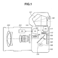
- FIG. 1 is a diagram schematically illustrating the construction of an imaging apparatus according to the exemplary embodiment of the present invention; the imaging apparatus is composed of a camera main body 100 and a lens unit 200 detachable from the camera main body 100.
- a microcomputer central processing unit (CPU) 101 controls each portion of the camera main body 100.
- An imaging device 102 such as a charge-coupled device (CCD) or a complementary metal oxide semiconductor (CMOS) including an infrared cut filter, a low-pass filter or the like photo-electrically converts light having entered the imaging apparatus via a photographing lens of the lens unit 200 to output an image signal.
- CCD charge-coupled device
- CMOS complementary metal oxide semiconductor
- a mechanical shutter 103 is operated to be switched between a state shielding the imaging device 102 from the light having entered via the photographing lens and a retracted state in which it guides the light having entered via the photographing lens to the imaging device 102.
- a half mirror 104 is movable to a position where it guides the light having entered via the photographing lens to the imaging device 102 (the mirror-up state: second state) and a position where it guides the light to a light metering sensor 106 (mirror-down state: first state).
- the half mirror 104 switches the optical path of the light having entered via the photographing lens between the state guiding the light to the imaging device 102 and the state guiding the light to the light metering sensor 106.
- the half mirror is at the position where it guides the light to the light metering sensor 106, the light having entered via the photographing lens is directed to a focusing plate 105 to form an image.
- the light metering sensor 106 includes an imaging device such as a CCD, which photo-electrically converts a subject image to accumulate electric charge to output an image signal.
- an imaging device such as a CCD
- the present exemplary embodiment described below employs, as the light metering sensor 106, a CCD having M x N pixels arranged in a matrix-like manner.
- a pentagonal prism 107 guides the light having entered via the photographing lens and reflected by the half mirror 104, to the light metering sensor 106 and an optical finder (not illustrated).
- Memory 108 such as random access memory (RAM), and read only memory (ROM) is connected to the CPU 101.
- An auto focus (AF) mirror 110 reflects a part of the light having entered via the photographing lens and passed through the half mirror 104, and guides it to an AF sensor in a focus detection circuit 109.
- the AF sensor has a plurality of AF regions in an imaging frame, making it possible to obtain the defocusing amount in each AF region.
- the CPU 101 transmits AF control information based on the output from the focus detection circuit 109 to a lens CPU 201 (hereinafter referred to as the LCPU) configured to control each portion of the lens unit 200.
- the LCPU 201 drives the photographing lens in the lens unit 200 based on the received AF control information to perform automatic focus adjustment control (hereinafter referred to as the AF control).
- a CPU 111 (hereinafter referred to as the ICPU) performs image processing and computation processing on an image signal output from the light metering sensor 106 after electric charge is accumulated.
- the ICPU performs subject tracking, light metering, face detection, etc. illustrated below based on the image signal output from the light metering sensor 106.
- the result of the light metering computation by the ICPU 111 is transmitted to the CPU 101, and the CPU 101 sets shutter speed, stop value, etc. based on the result of the light metering computation, and performs exposure control.
- Memory 112 such as RAM, and ROM is connected to the ICPU 111.
- the CPU for performing image processing and computation processing on the image signal output from the light metering sensor 106 is provided separately from the CPU for controlling each portion of the camera main body 100, it is also possible for a single CPU to perform both processing.
- the lens unit 200 may be contained in the camera main body 100 or the CPU 101 may drive the photographing lens to perform AF control.
- Fig. 2 illustrates the operational sequence in continuous shooting from the mirror-down state prior to the shooting of the Nth frame (N ⁇ 2) to the mirror-down state prior to the shooting of the (N + 2)th frame.
- the light metering sensor 106 performs accumulation a1 (first accumulation) in the mirror-down state.
- This accumulation a1 is performed in order to obtain an image signal to be used for subject tracking.
- the accumulation time is set by the ICPU 111 such that the continuous shooting speed at the time of continuous shooting is not reduced and that the result of the computation for the subject tracking can be reflected in the AF control.
- the accumulation time is set to a time shorter than the flicker period.
- the accumulation time is too short, a sufficient accumulation is not effected, and the computation for subject tracking cannot be performed, so that the accumulation time is set to a time as required for obtaining an image signal enabling the computation of subject tracking.
- accumulation by an AF sensor in the focus detection circuit 109 for performing the AF control is also performed in parallel with the accumulation a1.
- Defocusing amount computation etc. of each AF region is performed based on the result of the accumulation by the AF sensor. After that, AF control is performed based on the defocusing amount computation result, tracking computation result illustrated below, etc.
- subj ect tracking is performed based on the image signal obtained through accumulation a1, so that it is possible to perform an AF control in which the tracking result is reflected without reducing a shooting speed at the time of continuous shooting.
- a reading process Ra1 in which the image signals accumulated are read out, is started. Further, in parallel with the reading Ra1, accumulation b1 (second accumulation) is performed.
- This accumulation b1 is processing for performing a light metering computation in which the influence of the flicker is reduced; its setting is made such that the light metering computation can be completed until the start of the exposure control.
- the accumulation b1 may be started after the reading Ra1 has been completed. This also applies to the following reading and accumulation.
- the accumulation b1 is performed subsequent to the accumulation a1, and light metering computation is performed based on the image signal obtained through the accumulation a1 and the image signal obtained through the accumulation b1, so that it is possible to perform an exposure reducing the influence of the flicker.
- the luminance value based on the accumulated image signals varies depending upon a portion of the phase of the flicker period with which the accumulation a1 overlaps.
- the accumulation b1 is performed subsequent to the accumulation a1, and the light metering computation is performed based on the image signals accumulated in each of them.
- the total accumulation time of the image signals used for light metering computation is lengthened.
- the influence of the flicker is reduced as compared with the case in which the light metering computation is performed based solely on the image signals accumulated in the accumulation a1, making it possible to perform a more accurate exposure control.
- the phase of the overlapping flicker period is made different between the accumulation a1 and accumulation b1, so that the fluctuation in the average value of the flicker source light quantity during the accumulation periods combining the accumulation a1 and accumulation b1 is reduced, thus stabilizing the light metering computation result and making it possible to perform a more accurate exposure control.
- the sum total of the accumulation time of the accumulation a1 and the accumulation tie of the accumulation b1 is set to be substantially equal to an integral multiple of the flicker period, it is possible to further reduce the influence of the flicker.
- accumulation b1 when the accumulation b1 is completed, reading Rb1, in which the accumulated image signals are read out, is started. Further, accumulation c1 (third accumulation) is performed in parallel with the reading Rb1.
- This accumulation c1 is processing for obtaining an image signal to be used for the face detection of the subject.
- the face detection computation requires more time as compared with the tracking computation and light metering computation, so that if the detection result is to be reflected in the AF control or the like for the shooting performed immediately after the completion of the accumulation c1, a shooting speed is reduced at the time of continuous shooting. If the shooting speed is not to be reduced at the time of continuous shooting, the face detection computation cannot be completed in time for the AF control or the like for the shooting performed immediately after the completion of the accumulation c1. In view of this, the result of the face detection computation using the image signals obtained through the accumulation c1 is used for the AF control not for the shooting performed immediately after the completion of the accumulation c1 but for the next shooting.
- Reading Rc1 in which the image signals accumulated in the accumulation c1 are read can be executed even in the mirror-up state, so that the accumulation time of the accumulation c1 is set by the ICPU 111 such that the series of processing from the start of the accumulation a1 to the completion of the accumulation c1 are completed in the mirror-down state.
- a mirror-up operation is started before the reading Rc1, in which the image signals accumulated in the accumulation c1 are read, is completed.
- the face detection computation is performed after the mirror-up operation has been started.
- accumulations a2, b2, and c2 and accumulations a3, b3, and c3 are performed in the mirror-down state before the shooting of the (N + 1)th frame and the (N + 2)th frame is carried out.
- the accumulations a1, b1, and c1 are performed in the mirror-down state; however, it is also possible to perform an intermittent accumulation in each accumulation in order to reduce the influence of the flicker in various processing.
- the luminance value based on the accumulated image signals varies depending on a portion of the phase of the flicker period with which the accumulation period overlaps.
- a plurality of accumulations are performed intermittently, with each accumulation being performed for a time obtained by dividing the accumulation time when accumulation is performed collectively, by the number of accumulations.
- the accumulation time illustrated in Fig. 3A is equal to the sum total of the accumulation time of the plurality of accumulations illustrated in Fig. 3E .
- the image signal obtained through the intermittent accumulation is used as the image signal obtained through the accumulation a1.
- Such intermittent accumulation may also be executed in at least one of the accumulations a1, b1, and c1, or may be switched between whether intermittent accumulation is to be performed or not according to each accumulation time. For example, intermittent accumulation may be performed in the case where the accumulation time is shorter than the flicker period and where the influence of the flicker is expected to be great.
- a stripe type CCD is used as the light metering sensor 106.
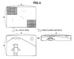
- the pixels of red (R), green (G), and blue (B) are arranged in a stripe-like manner as illustrated in Fig. 4 ; in such a stripe type CCD, it is possible to perform pixel addition in an analog manner in the vertical direction.
- the size of the image based on the read image signal is reduced to 1/4 in the vertical direction.
- the output level of the image signal is approximately four times the level when no pixel addition is performed (when all the pixels are read), so that it is possible to obtain an image of a brightness equivalent to that of the image based on the image signal read without performing pixel addition in an accumulation time reduced to approximately 1/4.
- the image signal read amount is also reduced as compared with that when no pixel addition is performed, so that it is possible to shorten the requisite time for image signal reading.
- the respective average outputs Ra, Ga, and Ba of the R, G, and B pixels are calculated to calculate the luminance value Yij of each light metering region from the calculated Ra, Ga, and Ba.
- the luminance Yij is obtained.
- weighted average computation is performed, in which a weight is assigned to the Yij of each light metering region according to the light metering mode such as evaluation light metering or spot light metering to obtain the luminance value of the entire light metering region.
- the above light metering computation is performed on the image signal obtained through the accumulation a1 and the image signal obtained through the accumulation b1 to acquire the respective luminance values Y1 and Y2.
- the final luminance value Y to be used for the exposure control can be expressed by the following equation (2).
- Y Y ⁇ 1 / T ⁇ 1 + Y ⁇ 2 / T ⁇ 2 ⁇ T ⁇ 1 / 2
- the above equation (2) is used to obtain the average value of the luminance values when the accumulations a1 and b1 are both performed in the accumulation time T1; however, the formula for obtaining the final luminance value is not restricted to equation (2). For example, it may also be an equation for obtaining the average value of the luminance values when the accumulations a1 and b1 are both performed in the accumulation time T2.
- the weighted average of the luminance value Y1 and the luminance value Y2 is obtained. Further, it may also be an equation for obtaining the average value of the luminance values when the accumulations a1 and b1 are both performed in a predetermined accumulation time Ts.
- equation (3) may also be employed, in which the accumulation time of the accumulation a1 and the accumulation time of the accumulation b1 are equalized and in which the accumulation time of each of them is reduced to half the flicker period, thus simplifying the weighted average computation.
- Y Y ⁇ 1 + Y ⁇ 2 / 2
- the accumulation time of the accumulations a1, b1, and c1 may be set to previously determined times, or may be set by the ICPU 111 based on the preceding light metering result. In the case where the setting is made by the ICPU 111 based on the result of the preceding light metering computation, the setting is made, for example, such that the accumulation time is shorter when the final luminance value Y is high than when the final luminance value Y obtained from the preceding light metering computation result is low.
- comparison is made, for example, between the image obtained through the accumulation a1 and the image obtained through the accumulation a2, and computation (pattern matching) is performed to determine where the tracking object has moved, based on the distribution of the luminance pattern and color pattern of the tracking object satisfying a predetermined condition. More specifically, tracking of an object satisfying a predetermined condition is performed in the shooting frame. And, AF control is performed while changing the AF region where focusing is effected following the movement of the tracking object. Alternatively, exposure control is performed while changing the weighting with respect to each light metering region following the movement of the tracking object.
- Fig. 6 is a diagram illustrating AF control following the movement of a tracking object.
- an AF frame 7 at the position where the main subject exits is set as the frame indicating the AF region for focusing to perform AF control.
- the AF frame set as the frame indicating the AF region for focusing is indicated by a frame thicker than the other AF frames.
- an accumulation is performed to obtain an image signal to be used for subject tracking.
- the ICPU 111 sets a predetermined region using the AF frame 7 as a reference as the tracking region in the obtained image. In the tracking region, the matching of luminance pattern and color pattern is performed in the tracking computation. While it is also possible to read the image signal used for the subject tracking computation by performing pixel addition, in the case of the image illustrated in Figs. 6A through 6D , all pixels are read.
- the ICPU 111 sets a predetermined region, using the tracking region set based on the AF frame 7 as a reference, as a search region, which is a region where the tracking object is searched for.
- the search region includes the tracking region, and is set to be larger than the tracking region.
- the ICPU 111 determines whether there exists a region matching the tracking region of the image obtained the last time in terms of luminance pattern and color pattern.
- the search region is set large, tracking is possible even if the position of the tracking object has greatly changed; however, the larger the search region, the longer the requisite time for determination, so that the search region is set by taking into account the tracking accuracy and the time that can be utilized for the tracking computation.
- the AF frame existing within the region is set as the AF frame indicating the AF region where the next focusing is effected.
- the AF frame 8 corresponds to that frame. Then, shooting is performed after AF control has been performed so as to effect focusing in a region corresponding to the AF frame 8.
- the ICPU 111 newly sets a region matching the tracking region of the image obtained previously, in the image obtained currently, as the tracking region.
- the ICPU 111 sets the search region using the position of the tracking region as a reference. More specifically, since the tracking region newly set the last time is a region centering on the AF frame 8, the search region is accordingly changed from the preceding one.
- Fig. 6D in which the position of the main subject has moved from the position in Fig. 6C , the search region is changed to perform the search of the tracking object.
- tracking computation is performed prior to each shooting at the time of continuous shooting, so that it is always possible to perform shooting focusing on the main subject taken as the tracking object in the initial state.
- the tracking computation can be performed based on the tracking region of Fig. 6B . More specifically, the search of a region matching the tracking region of the image illustrated in Fig. 6B is performed. In this case, the position of the subject is expected to change more than in the case where the tracking computation is performed between successive images, so that the search may be performed by setting the search region wider than normal.
- the tracking object may be re-set again.
- the accumulation time of each image used for the tracking computation of the subject is shorter than the flicker period, brightness may vary due to the influence of the flicker.
- image comparison may be performed after processing for making a brightness level of the images substantially the same is carried out.
- Fig. 7 is a diagram illustrating an AF control following the movement of the tracking object in the case where the face detection result is used.
- the technique for detecting a human face any one of the well-known methods may be adopted; for example, it is possible to adopt a method in which light metering data is transformed into hue and saturation. By preparing and analyzing a two-dimensional histogram thereof, a face region can be determined. Alternatively, it is possible to adopt a method in which a face candidate region corresponding to human face features is extracted and a face region is determined from the feature amount in the region.
- AF control is performed so as to focus on the AF region corresponding to the AF frame 7 situated where the main subj ect exists.
- the AF frame set as the frame indicating the AF region where focusing is effected is indicated by a thicker frame than the other AF frames.
- a region other than the face of the main subject may be set as the AF region where focusing is effected.
- accumulation is performed to obtain the image signal to be used for subject tracking and accumulation to obtain the image signal to be used for the subject face detection.
- face detection computation is performed based on the obtained image signal to set the subject face region detected as the tracking region in the image to be used for the subject tracking.
- a search region is set using the position of the tracking region in the image obtained the last time as a reference. More specifically, in the image illustrated in Fig. 7A , a region near the AF frame 2 is used as the subject face region according to the face detection computation, and this face region is set as the tracking region, so that the search region is set to a predetermined region using this face detection region as a reference.
- a search is made as to whether there exists a region matching the luminance pattern and color pattern of the tracking region of the image obtained the last time.
- the AF frame existing in that region is set as the AF frame indicating the AF region for the next focusing.
- the AF frame 3 corresponds to that frame. Then, shooting is performed after AF control is performed so as to focus on a region corresponding to the AF frame 3.
- the face detection computation using the image signals accumulated when the subject exists at the position of Fig. 7B cannot be performed in time for the AF control, so that the result of the face detection computation is used for the tracking computation in the next AF control.
- face detection computation is performed using the image signals accumulated when the subject exists at the position of Fig. 7B .
- the detected subject face region is newly set as the tracking region in the image to be used for subject tracking. In this way, by setting the tracking region of each tracking computation based on the result of the face detection computation, it is possible to accurately track the face region of the tracking object.
- a region matching the preceding tracking region in the image used for the subject tracking computation obtained this time and the detected subject face region are substantially the same, a region matching the preceding tracking region may be set as the new tracking region.
- the accumulation is performed to obtain the image signal to be used for the next subject tracking and the accumulation is performed to obtain the image signal to be used for the subject face detection.
- a search region is set using the position of the tracking region in the image obtained last time. More specifically, the tracking region of the preceding image is a region which centers on the AF frame 3 where the subject face region exists in the state of Fig. 7B , so that the search region is accordingly changed from the preceding one.
- the AF frame existing within that region is set as the AF frame indicating the AF region for the next focusing.
- the AF frame 4 corresponds to that frame. Then, shooting is performed after AF control has been performed to focus on the region corresponding to the AF frame 4.
- the tracking object is searched for, while the face region is detected by the face detection computation using the image signals accumulated when the subject exists at the position of Fig. 7C , the face region being set as the tracking region for the search.
- tracking computation is performed using the face detection result, prior to each shooting at the time of continuous shooting, so that it is always possible to perform shooting while focusing on the main subject used as the tracking object in the initial state, in particular, the face region of the main subject.
- the AF control is performed to focus on the AF region corresponding to the face region of the detected subject.
- the subject distance is regarded substantially equal to that in the face region, so that in the case, for example, where no AF region corresponding to the face region of the subject detected exists, focusing may be effected on the AF region corresponding to the region below the face region of the detected subject.
- accumulation operation by the light metering sensor 106 is performed a plurality of times prior to each shooting at the time of continuous shooting, and subject tracking is performed based on the image signals obtained through the first accumulation operation, so that it is possible to perform subject tracking without reducing a shooting speed at the time of continuous shooting.
- exposure control is performed based on image signals obtained through accumulation operation performed a plurality of times, so that when the accumulation time of a single accumulation operation is shorter than the flicker period, it is possible to perform exposure control reducing the influence of the flicker.
- the face detection result based on the image signals obtained through accumulation by the light metering sensor 10 in the preceding mirror-down state is used in the tracking computation for the shooting this time. Therefore, it is possible to perform subject tracking in which the detection result of the subject detection is reflected, without reducing a continuous shooting speed.
- the luminance pattern and color pattern serving as a reference in tracking computation are updated each time an image to be used for subject tracking is obtained, it is also possible to perform tracking computation while maintaining the luminance pattern and color pattern first determined as the tracking reference.
- the accumulation for light metering computation is performed a plurality of times, such as accumulation a1 and accumulation b1, it is not necessary to perform the accumulation for light metering computation a plurality of times in the case where continuous shooting is not performed or in the case where sufficient accumulation time can be secured by a single accumulation, for example, before the shooting of the first frame in continuous shooting.
- the accumulation for light metering computation may be performed a plurality of times even in the case where continuous shooting is not performed or in the case where sufficient accumulation time can be secured by a single accumulation, for example, before the shooting of the first frame in continuous shooting.
- the accumulation for light metering computation is performed a plurality of times.
- the accumulation for light metering computation is performed a plurality of times when the continuous shooting speed is not higher than the predetermined value.
- accumulation a1 and accumulation b1 there is no need to employ the image signals obtained through the accumulation a1 for the light metering computation if sufficient accumulation time is secured in the accumulation b1.
- the accumulation for light metering computation may be performed in a larger quantity than in the exemplary embodiment illustrated above.
- the detection of the face region of a human subject is performed through face detection computation
- the user may previously set a subject region as the detection object, and the set subject region may be detected in the subject detection computation thereafter.
- An imaging apparatus including an electric charge accumulation unit configured to accumulate electric charge in accordance with an incident light quantity; a tracking unit configured to perform tracking; and an exposure control unit configured to perform exposure control, wherein the electric charge accumulation unit performs a first accumulation, and then performs a second accumulation after the first accumulation, wherein the tracking unit performs the tracking based on an image signal obtained through the first accumulation, and wherein the exposure control unit computes a control value for the exposure control based on at least the image signal obtained through the second accumulation of the image signal obtained through the first accumulation and an image signal obtained through the second accumulation.
Landscapes
- Engineering & Computer Science (AREA)
- Multimedia (AREA)
- Signal Processing (AREA)
- Physics & Mathematics (AREA)
- General Physics & Mathematics (AREA)
- Studio Devices (AREA)
- Optical Radar Systems And Details Thereof (AREA)
- Transforming Light Signals Into Electric Signals (AREA)
- Automatic Focus Adjustment (AREA)
Applications Claiming Priority (3)
| Application Number | Priority Date | Filing Date | Title |
|---|---|---|---|
| JP2011029996A JP5762038B2 (ja) | 2011-02-15 | 2011-02-15 | 撮像装置及び制御方法 |
| JP2011029970A JP5762037B2 (ja) | 2011-02-15 | 2011-02-15 | 撮像装置及び制御方法 |
| EP12155352.3A EP2512120B1 (de) | 2011-02-15 | 2012-02-14 | Bilderzeugungsvorrichtung und Steuerungsverfahren |
Related Parent Applications (2)
| Application Number | Title | Priority Date | Filing Date |
|---|---|---|---|
| EP12155352.3A Division EP2512120B1 (de) | 2011-02-15 | 2012-02-14 | Bilderzeugungsvorrichtung und Steuerungsverfahren |
| EP12155352.3A Division-Into EP2512120B1 (de) | 2011-02-15 | 2012-02-14 | Bilderzeugungsvorrichtung und Steuerungsverfahren |
Publications (3)
| Publication Number | Publication Date |
|---|---|
| EP2768215A2 true EP2768215A2 (de) | 2014-08-20 |
| EP2768215A3 EP2768215A3 (de) | 2014-08-27 |
| EP2768215B1 EP2768215B1 (de) | 2017-04-12 |
Family
ID=45655719
Family Applications (2)
| Application Number | Title | Priority Date | Filing Date |
|---|---|---|---|
| EP14164137.3A Not-in-force EP2768215B1 (de) | 2011-02-15 | 2012-02-14 | Bilderzeugungsvorrichtung und Steuerungsverfahren |
| EP12155352.3A Active EP2512120B1 (de) | 2011-02-15 | 2012-02-14 | Bilderzeugungsvorrichtung und Steuerungsverfahren |
Family Applications After (1)
| Application Number | Title | Priority Date | Filing Date |
|---|---|---|---|
| EP12155352.3A Active EP2512120B1 (de) | 2011-02-15 | 2012-02-14 | Bilderzeugungsvorrichtung und Steuerungsverfahren |
Country Status (3)
| Country | Link |
|---|---|
| US (2) | US9374533B2 (de) |
| EP (2) | EP2768215B1 (de) |
| CN (1) | CN102685383B (de) |
Families Citing this family (10)
| Publication number | Priority date | Publication date | Assignee | Title |
|---|---|---|---|---|
| US9374533B2 (en) | 2011-02-15 | 2016-06-21 | Canon Kabushiki Kaisha | Imaging apparatus and control method for tracking a subject based on an image signal |
| JP5925186B2 (ja) * | 2011-03-17 | 2016-05-25 | キヤノン株式会社 | 撮像装置及びその制御方法 |
| JP6046905B2 (ja) * | 2012-04-02 | 2016-12-21 | キヤノン株式会社 | 撮像装置、露出制御方法、及びプログラム |
| KR101889932B1 (ko) * | 2012-07-25 | 2018-09-28 | 삼성전자주식회사 | 촬영 장치 및 이에 적용되는 촬영 방법 |
| FR3005543A1 (fr) * | 2013-10-14 | 2014-11-14 | St Microelectronics Grenoble 2 | Procede de compensation de scintillement utilisant deux images |
| JP6579609B2 (ja) * | 2015-07-13 | 2019-09-25 | オリンパス株式会社 | カメラシステム、そのブレ補正方法、及びカメラボディ |
| JP6626332B2 (ja) * | 2015-12-09 | 2019-12-25 | キヤノン株式会社 | 撮像装置及びその制御方法 |
| WO2018018514A1 (en) * | 2016-07-28 | 2018-02-01 | SZ DJI Technology Co., Ltd. | Target-based image exposure adjustment |
| CN111212242B (zh) * | 2020-01-14 | 2021-03-12 | 维沃移动通信有限公司 | 曝光方法和电子设备 |
| JP7536541B2 (ja) * | 2020-07-16 | 2024-08-20 | キヤノン株式会社 | 撮像装置およびその制御方法 |
Citations (2)
| Publication number | Priority date | Publication date | Assignee | Title |
|---|---|---|---|---|
| JPH07110429A (ja) | 1993-10-08 | 1995-04-25 | Nikon Corp | 被写体追尾機能を有するカメラ |
| EP2512120A1 (de) | 2011-02-15 | 2012-10-17 | Canon Kabushiki Kaisha | Bilderzeugungsvorrichtung und Steuerungsverfahren |
Family Cites Families (10)
| Publication number | Priority date | Publication date | Assignee | Title |
|---|---|---|---|---|
| JP4040139B2 (ja) * | 1997-05-12 | 2008-01-30 | キヤノン株式会社 | カメラ |
| JP3952989B2 (ja) * | 2003-04-30 | 2007-08-01 | 住友電気工業株式会社 | カメラ式車両感知器の露光制御方法及び装置 |
| JP4173457B2 (ja) * | 2004-03-12 | 2008-10-29 | 富士フイルム株式会社 | 撮影装置及びその制御方法 |
| JP4576295B2 (ja) | 2005-06-27 | 2010-11-04 | オリンパスイメージング株式会社 | デジタルカメラ |
| JP5070728B2 (ja) | 2006-04-04 | 2012-11-14 | 株式会社ニコン | カメラ |
| JP4910462B2 (ja) | 2006-04-14 | 2012-04-04 | 株式会社ニコン | カメラ |
| JP5072431B2 (ja) * | 2007-05-15 | 2012-11-14 | キヤノン株式会社 | 撮像装置及びその制御方法 |
| JP2008287064A (ja) | 2007-05-18 | 2008-11-27 | Sony Corp | 撮像装置 |
| JP5233720B2 (ja) | 2009-02-12 | 2013-07-10 | ソニー株式会社 | 撮像装置、撮像装置の制御方法およびプログラム |
| JP2012133172A (ja) | 2010-12-22 | 2012-07-12 | Nikon Corp | カメラ |
-
2012
- 2012-02-09 US US13/369,923 patent/US9374533B2/en not_active Expired - Fee Related
- 2012-02-14 EP EP14164137.3A patent/EP2768215B1/de not_active Not-in-force
- 2012-02-14 EP EP12155352.3A patent/EP2512120B1/de active Active
- 2012-02-15 CN CN201210034273.9A patent/CN102685383B/zh active Active
-
2016
- 2016-05-23 US US15/161,912 patent/US9674424B2/en active Active
Patent Citations (2)
| Publication number | Priority date | Publication date | Assignee | Title |
|---|---|---|---|---|
| JPH07110429A (ja) | 1993-10-08 | 1995-04-25 | Nikon Corp | 被写体追尾機能を有するカメラ |
| EP2512120A1 (de) | 2011-02-15 | 2012-10-17 | Canon Kabushiki Kaisha | Bilderzeugungsvorrichtung und Steuerungsverfahren |
Also Published As
| Publication number | Publication date |
|---|---|
| EP2768215A3 (de) | 2014-08-27 |
| EP2512120A1 (de) | 2012-10-17 |
| EP2512120B1 (de) | 2014-05-28 |
| US9674424B2 (en) | 2017-06-06 |
| EP2768215B1 (de) | 2017-04-12 |
| US20120206640A1 (en) | 2012-08-16 |
| CN102685383B (zh) | 2014-12-24 |
| CN102685383A (zh) | 2012-09-19 |
| US9374533B2 (en) | 2016-06-21 |
| US20160269618A1 (en) | 2016-09-15 |
Similar Documents
| Publication | Publication Date | Title |
|---|---|---|
| EP2768215B1 (de) | Bilderzeugungsvorrichtung und Steuerungsverfahren | |
| US9648249B2 (en) | Image capturing apparatus, method of controlling the same, and storage medium | |
| US6670992B2 (en) | Camera having light measuring device operable based on focus detecting device | |
| US8542941B2 (en) | Imaging device, image detecting method and focus adjusting method | |
| EP2605511B1 (de) | Bilderfassungsvorrichtung und Fokuserkennungsverfahren | |
| US10033919B2 (en) | Focus adjusting apparatus, focus adjusting method, image capturing apparatus, and storage medium | |
| US9210346B2 (en) | Focus detection sensor and optical apparatus using the same | |
| US7991280B2 (en) | Focus adjusting apparatus and focus adjusting method | |
| JP2013089991A (ja) | 撮像装置 | |
| RU2549143C1 (ru) | Устройство регистрации изображения и способ управления им | |
| US8369699B2 (en) | Focus detection apparatus | |
| US10594938B2 (en) | Image processing apparatus, imaging apparatus, and method for controlling image processing apparatus | |
| US9602716B2 (en) | Focus-detection device, method for controlling the same, and image capture apparatus | |
| US10412330B2 (en) | Image capture apparatus and method for controlling the same | |
| JPH10160410A (ja) | 測距装置 | |
| JP5361598B2 (ja) | 焦点調節装置及び方法、及び撮像装置 | |
| JP5762037B2 (ja) | 撮像装置及び制御方法 | |
| JP2012203314A (ja) | 撮像装置及び撮像装置の制御方法 | |
| US20180203204A1 (en) | Focus detection apparatus, control method, and storage medium | |
| JP5762038B2 (ja) | 撮像装置及び制御方法 | |
| JP6806471B2 (ja) | 焦点検出装置及び方法、及び撮像装置 | |
| JP2013040994A (ja) | 撮像装置 | |
| JP2010272966A (ja) | 測光装置及び撮像装置 | |
| US20200099842A1 (en) | Image capturing apparatus and control method thereof, and storage medium | |
| JP4286077B2 (ja) | ストロボ調光機能付きカメラ |
Legal Events
| Date | Code | Title | Description |
|---|---|---|---|
| PUAL | Search report despatched |
Free format text: ORIGINAL CODE: 0009013 |
|
| PUAI | Public reference made under article 153(3) epc to a published international application that has entered the european phase |
Free format text: ORIGINAL CODE: 0009012 |
|
| 17P | Request for examination filed |
Effective date: 20140410 |
|
| AC | Divisional application: reference to earlier application |
Ref document number: 2512120 Country of ref document: EP Kind code of ref document: P |
|
| AK | Designated contracting states |
Kind code of ref document: A2 Designated state(s): AL AT BE BG CH CY CZ DE DK EE ES FI FR GB GR HR HU IE IS IT LI LT LU LV MC MK MT NL NO PL PT RO RS SE SI SK SM TR |
|
| AK | Designated contracting states |
Kind code of ref document: A3 Designated state(s): AL AT BE BG CH CY CZ DE DK EE ES FI FR GB GR HR HU IE IS IT LI LT LU LV MC MK MT NL NO PL PT RO RS SE SI SK SM TR |
|
| RIC1 | Information provided on ipc code assigned before grant |
Ipc: G03B 19/12 20060101ALI20140718BHEP Ipc: H04N 5/232 20060101AFI20140718BHEP |
|
| R17P | Request for examination filed (corrected) |
Effective date: 20150227 |
|
| RBV | Designated contracting states (corrected) |
Designated state(s): AL AT BE BG CH CY CZ DE DK EE ES FI FR GB GR HR HU IE IS IT LI LT LU LV MC MK MT NL NO PL PT RO RS SE SI SK SM TR |
|
| GRAP | Despatch of communication of intention to grant a patent |
Free format text: ORIGINAL CODE: EPIDOSNIGR1 |
|
| INTG | Intention to grant announced |
Effective date: 20161005 |
|
| RAP1 | Party data changed (applicant data changed or rights of an application transferred) |
Owner name: CANON KABUSHIKI KAISHA |
|
| RIN1 | Information on inventor provided before grant (corrected) |
Inventor name: NAKAGAWARA, NAOYUKI |
|
| GRAS | Grant fee paid |
Free format text: ORIGINAL CODE: EPIDOSNIGR3 |
|
| GRAA | (expected) grant |
Free format text: ORIGINAL CODE: 0009210 |
|
| AC | Divisional application: reference to earlier application |
Ref document number: 2512120 Country of ref document: EP Kind code of ref document: P |
|
| AK | Designated contracting states |
Kind code of ref document: B1 Designated state(s): AL AT BE BG CH CY CZ DE DK EE ES FI FR GB GR HR HU IE IS IT LI LT LU LV MC MK MT NL NO PL PT RO RS SE SI SK SM TR |
|
| REG | Reference to a national code |
Ref country code: GB Ref legal event code: FG4D |
|
| REG | Reference to a national code |
Ref country code: CH Ref legal event code: EP |
|
| REG | Reference to a national code |
Ref country code: IE Ref legal event code: FG4D |
|
| REG | Reference to a national code |
Ref country code: AT Ref legal event code: REF Ref document number: 884879 Country of ref document: AT Kind code of ref document: T Effective date: 20170515 |
|
| REG | Reference to a national code |
Ref country code: DE Ref legal event code: R096 Ref document number: 602012031216 Country of ref document: DE |
|
| REG | Reference to a national code |
Ref country code: NL Ref legal event code: MP Effective date: 20170412 |
|
| REG | Reference to a national code |
Ref country code: LT Ref legal event code: MG4D |
|
| REG | Reference to a national code |
Ref country code: AT Ref legal event code: MK05 Ref document number: 884879 Country of ref document: AT Kind code of ref document: T Effective date: 20170412 |
|
| PG25 | Lapsed in a contracting state [announced via postgrant information from national office to epo] |
Ref country code: NL Free format text: LAPSE BECAUSE OF FAILURE TO SUBMIT A TRANSLATION OF THE DESCRIPTION OR TO PAY THE FEE WITHIN THE PRESCRIBED TIME-LIMIT Effective date: 20170412 |
|
| PG25 | Lapsed in a contracting state [announced via postgrant information from national office to epo] |
Ref country code: GR Free format text: LAPSE BECAUSE OF FAILURE TO SUBMIT A TRANSLATION OF THE DESCRIPTION OR TO PAY THE FEE WITHIN THE PRESCRIBED TIME-LIMIT Effective date: 20170713 Ref country code: FI Free format text: LAPSE BECAUSE OF FAILURE TO SUBMIT A TRANSLATION OF THE DESCRIPTION OR TO PAY THE FEE WITHIN THE PRESCRIBED TIME-LIMIT Effective date: 20170412 Ref country code: HR Free format text: LAPSE BECAUSE OF FAILURE TO SUBMIT A TRANSLATION OF THE DESCRIPTION OR TO PAY THE FEE WITHIN THE PRESCRIBED TIME-LIMIT Effective date: 20170412 Ref country code: LT Free format text: LAPSE BECAUSE OF FAILURE TO SUBMIT A TRANSLATION OF THE DESCRIPTION OR TO PAY THE FEE WITHIN THE PRESCRIBED TIME-LIMIT Effective date: 20170412 Ref country code: AT Free format text: LAPSE BECAUSE OF FAILURE TO SUBMIT A TRANSLATION OF THE DESCRIPTION OR TO PAY THE FEE WITHIN THE PRESCRIBED TIME-LIMIT Effective date: 20170412 Ref country code: ES Free format text: LAPSE BECAUSE OF FAILURE TO SUBMIT A TRANSLATION OF THE DESCRIPTION OR TO PAY THE FEE WITHIN THE PRESCRIBED TIME-LIMIT Effective date: 20170412 Ref country code: NO Free format text: LAPSE BECAUSE OF FAILURE TO SUBMIT A TRANSLATION OF THE DESCRIPTION OR TO PAY THE FEE WITHIN THE PRESCRIBED TIME-LIMIT Effective date: 20170712 |
|
| PG25 | Lapsed in a contracting state [announced via postgrant information from national office to epo] |
Ref country code: RS Free format text: LAPSE BECAUSE OF FAILURE TO SUBMIT A TRANSLATION OF THE DESCRIPTION OR TO PAY THE FEE WITHIN THE PRESCRIBED TIME-LIMIT Effective date: 20170412 Ref country code: LV Free format text: LAPSE BECAUSE OF FAILURE TO SUBMIT A TRANSLATION OF THE DESCRIPTION OR TO PAY THE FEE WITHIN THE PRESCRIBED TIME-LIMIT Effective date: 20170412 Ref country code: PL Free format text: LAPSE BECAUSE OF FAILURE TO SUBMIT A TRANSLATION OF THE DESCRIPTION OR TO PAY THE FEE WITHIN THE PRESCRIBED TIME-LIMIT Effective date: 20170412 Ref country code: BG Free format text: LAPSE BECAUSE OF FAILURE TO SUBMIT A TRANSLATION OF THE DESCRIPTION OR TO PAY THE FEE WITHIN THE PRESCRIBED TIME-LIMIT Effective date: 20170712 Ref country code: SE Free format text: LAPSE BECAUSE OF FAILURE TO SUBMIT A TRANSLATION OF THE DESCRIPTION OR TO PAY THE FEE WITHIN THE PRESCRIBED TIME-LIMIT Effective date: 20170412 Ref country code: IS Free format text: LAPSE BECAUSE OF FAILURE TO SUBMIT A TRANSLATION OF THE DESCRIPTION OR TO PAY THE FEE WITHIN THE PRESCRIBED TIME-LIMIT Effective date: 20170812 |
|
| REG | Reference to a national code |
Ref country code: DE Ref legal event code: R097 Ref document number: 602012031216 Country of ref document: DE |
|
| PG25 | Lapsed in a contracting state [announced via postgrant information from national office to epo] |
Ref country code: EE Free format text: LAPSE BECAUSE OF FAILURE TO SUBMIT A TRANSLATION OF THE DESCRIPTION OR TO PAY THE FEE WITHIN THE PRESCRIBED TIME-LIMIT Effective date: 20170412 Ref country code: SK Free format text: LAPSE BECAUSE OF FAILURE TO SUBMIT A TRANSLATION OF THE DESCRIPTION OR TO PAY THE FEE WITHIN THE PRESCRIBED TIME-LIMIT Effective date: 20170412 Ref country code: CZ Free format text: LAPSE BECAUSE OF FAILURE TO SUBMIT A TRANSLATION OF THE DESCRIPTION OR TO PAY THE FEE WITHIN THE PRESCRIBED TIME-LIMIT Effective date: 20170412 Ref country code: DK Free format text: LAPSE BECAUSE OF FAILURE TO SUBMIT A TRANSLATION OF THE DESCRIPTION OR TO PAY THE FEE WITHIN THE PRESCRIBED TIME-LIMIT Effective date: 20170412 Ref country code: RO Free format text: LAPSE BECAUSE OF FAILURE TO SUBMIT A TRANSLATION OF THE DESCRIPTION OR TO PAY THE FEE WITHIN THE PRESCRIBED TIME-LIMIT Effective date: 20170412 |
|
| PLBE | No opposition filed within time limit |
Free format text: ORIGINAL CODE: 0009261 |
|
| STAA | Information on the status of an ep patent application or granted ep patent |
Free format text: STATUS: NO OPPOSITION FILED WITHIN TIME LIMIT |
|
| PG25 | Lapsed in a contracting state [announced via postgrant information from national office to epo] |
Ref country code: IT Free format text: LAPSE BECAUSE OF FAILURE TO SUBMIT A TRANSLATION OF THE DESCRIPTION OR TO PAY THE FEE WITHIN THE PRESCRIBED TIME-LIMIT Effective date: 20170412 Ref country code: SM Free format text: LAPSE BECAUSE OF FAILURE TO SUBMIT A TRANSLATION OF THE DESCRIPTION OR TO PAY THE FEE WITHIN THE PRESCRIBED TIME-LIMIT Effective date: 20170412 |
|
| 26N | No opposition filed |
Effective date: 20180115 |
|
| PG25 | Lapsed in a contracting state [announced via postgrant information from national office to epo] |
Ref country code: SI Free format text: LAPSE BECAUSE OF FAILURE TO SUBMIT A TRANSLATION OF THE DESCRIPTION OR TO PAY THE FEE WITHIN THE PRESCRIBED TIME-LIMIT Effective date: 20170412 |
|
| REG | Reference to a national code |
Ref country code: CH Ref legal event code: PL |
|
| PG25 | Lapsed in a contracting state [announced via postgrant information from national office to epo] |
Ref country code: MC Free format text: LAPSE BECAUSE OF FAILURE TO SUBMIT A TRANSLATION OF THE DESCRIPTION OR TO PAY THE FEE WITHIN THE PRESCRIBED TIME-LIMIT Effective date: 20170412 |
|
| REG | Reference to a national code |
Ref country code: IE Ref legal event code: MM4A |
|
| REG | Reference to a national code |
Ref country code: BE Ref legal event code: MM Effective date: 20180228 |
|
| PG25 | Lapsed in a contracting state [announced via postgrant information from national office to epo] |
Ref country code: LU Free format text: LAPSE BECAUSE OF NON-PAYMENT OF DUE FEES Effective date: 20180214 Ref country code: CH Free format text: LAPSE BECAUSE OF NON-PAYMENT OF DUE FEES Effective date: 20180228 Ref country code: LI Free format text: LAPSE BECAUSE OF NON-PAYMENT OF DUE FEES Effective date: 20180228 |
|
| REG | Reference to a national code |
Ref country code: FR Ref legal event code: ST Effective date: 20181031 |
|
| PG25 | Lapsed in a contracting state [announced via postgrant information from national office to epo] |
Ref country code: IE Free format text: LAPSE BECAUSE OF NON-PAYMENT OF DUE FEES Effective date: 20180214 |
|
| PG25 | Lapsed in a contracting state [announced via postgrant information from national office to epo] |
Ref country code: FR Free format text: LAPSE BECAUSE OF NON-PAYMENT OF DUE FEES Effective date: 20180228 Ref country code: BE Free format text: LAPSE BECAUSE OF NON-PAYMENT OF DUE FEES Effective date: 20180228 |
|
| PG25 | Lapsed in a contracting state [announced via postgrant information from national office to epo] |
Ref country code: MT Free format text: LAPSE BECAUSE OF NON-PAYMENT OF DUE FEES Effective date: 20180214 |
|
| PG25 | Lapsed in a contracting state [announced via postgrant information from national office to epo] |
Ref country code: TR Free format text: LAPSE BECAUSE OF FAILURE TO SUBMIT A TRANSLATION OF THE DESCRIPTION OR TO PAY THE FEE WITHIN THE PRESCRIBED TIME-LIMIT Effective date: 20170412 |
|
| PG25 | Lapsed in a contracting state [announced via postgrant information from national office to epo] |
Ref country code: PT Free format text: LAPSE BECAUSE OF FAILURE TO SUBMIT A TRANSLATION OF THE DESCRIPTION OR TO PAY THE FEE WITHIN THE PRESCRIBED TIME-LIMIT Effective date: 20170412 Ref country code: HU Free format text: LAPSE BECAUSE OF FAILURE TO SUBMIT A TRANSLATION OF THE DESCRIPTION OR TO PAY THE FEE WITHIN THE PRESCRIBED TIME-LIMIT; INVALID AB INITIO Effective date: 20120214 |
|
| PG25 | Lapsed in a contracting state [announced via postgrant information from national office to epo] |
Ref country code: MK Free format text: LAPSE BECAUSE OF NON-PAYMENT OF DUE FEES Effective date: 20170412 Ref country code: CY Free format text: LAPSE BECAUSE OF FAILURE TO SUBMIT A TRANSLATION OF THE DESCRIPTION OR TO PAY THE FEE WITHIN THE PRESCRIBED TIME-LIMIT Effective date: 20170412 |
|
| PG25 | Lapsed in a contracting state [announced via postgrant information from national office to epo] |
Ref country code: AL Free format text: LAPSE BECAUSE OF FAILURE TO SUBMIT A TRANSLATION OF THE DESCRIPTION OR TO PAY THE FEE WITHIN THE PRESCRIBED TIME-LIMIT Effective date: 20170412 |
|
| PGFP | Annual fee paid to national office [announced via postgrant information from national office to epo] |
Ref country code: GB Payment date: 20210120 Year of fee payment: 10 Ref country code: DE Payment date: 20210120 Year of fee payment: 10 |
|
| REG | Reference to a national code |
Ref country code: DE Ref legal event code: R119 Ref document number: 602012031216 Country of ref document: DE |
|
| GBPC | Gb: european patent ceased through non-payment of renewal fee |
Effective date: 20220214 |
|
| PG25 | Lapsed in a contracting state [announced via postgrant information from national office to epo] |
Ref country code: GB Free format text: LAPSE BECAUSE OF NON-PAYMENT OF DUE FEES Effective date: 20220214 Ref country code: DE Free format text: LAPSE BECAUSE OF NON-PAYMENT OF DUE FEES Effective date: 20220901 |