EP2768444B1 - Système et procédé pour alimenter des implants oculaires - Google Patents
Système et procédé pour alimenter des implants oculaires Download PDFInfo
- Publication number
- EP2768444B1 EP2768444B1 EP12809447.1A EP12809447A EP2768444B1 EP 2768444 B1 EP2768444 B1 EP 2768444B1 EP 12809447 A EP12809447 A EP 12809447A EP 2768444 B1 EP2768444 B1 EP 2768444B1
- Authority
- EP
- European Patent Office
- Prior art keywords
- implant
- transmitter
- flux
- antenna
- eye
- Prior art date
- Legal status (The legal status is an assumption and is not a legal conclusion. Google has not performed a legal analysis and makes no representation as to the accuracy of the status listed.)
- Active
Links
Images


Classifications
-
- A—HUMAN NECESSITIES
- A61—MEDICAL OR VETERINARY SCIENCE; HYGIENE
- A61F—FILTERS IMPLANTABLE INTO BLOOD VESSELS; PROSTHESES; DEVICES PROVIDING PATENCY TO, OR PREVENTING COLLAPSING OF, TUBULAR STRUCTURES OF THE BODY, e.g. STENTS; ORTHOPAEDIC, NURSING OR CONTRACEPTIVE DEVICES; FOMENTATION; TREATMENT OR PROTECTION OF EYES OR EARS; BANDAGES, DRESSINGS OR ABSORBENT PADS; FIRST-AID KITS
- A61F9/00—Methods or devices for treatment of the eyes; Devices for putting in contact-lenses; Devices to correct squinting; Apparatus to guide the blind; Protective devices for the eyes, carried on the body or in the hand
- A61F9/007—Methods or devices for eye surgery
- A61F9/00781—Apparatus for modifying intraocular pressure, e.g. for glaucoma treatment
-
- G—PHYSICS
- G02—OPTICS
- G02C—SPECTACLES; SUNGLASSES OR GOGGLES INSOFAR AS THEY HAVE THE SAME FEATURES AS SPECTACLES; CONTACT LENSES
- G02C11/00—Non-optical adjuncts; Attachment thereof
- G02C11/10—Electronic devices other than hearing aids
-
- A—HUMAN NECESSITIES
- A61—MEDICAL OR VETERINARY SCIENCE; HYGIENE
- A61F—FILTERS IMPLANTABLE INTO BLOOD VESSELS; PROSTHESES; DEVICES PROVIDING PATENCY TO, OR PREVENTING COLLAPSING OF, TUBULAR STRUCTURES OF THE BODY, e.g. STENTS; ORTHOPAEDIC, NURSING OR CONTRACEPTIVE DEVICES; FOMENTATION; TREATMENT OR PROTECTION OF EYES OR EARS; BANDAGES, DRESSINGS OR ABSORBENT PADS; FIRST-AID KITS
- A61F2250/00—Special features of prostheses classified in groups A61F2/00 - A61F2/26 or A61F2/82 or A61F9/00 or A61F11/00 or subgroups thereof
- A61F2250/0001—Means for transferring electromagnetic energy to implants
Definitions
- the present disclosure relates generally to systems and methods for powering ocular implants for use in ophthalmic treatments.
- Glaucoma a group of eye diseases affecting the retina and optic nerve, is one of the leading causes of blindness worldwide. Most forms of glaucoma result when the intraocular pressure (IOP) increases to pressures above normal for prolonged periods of time. IOP can increase due to high resistance to the drainage of the aqueous humor relative to its production. Left untreated, an elevated IOP causes irreversible damage to the optic nerve and retinal fibers resulting in a progressive, permanent loss of vision.
- IOP intraocular pressure
- Fig. 1 is a diagram of the front portion of an eye that helps to explain the processes of glaucoma.
- representations of the lens 110, cornea 120, iris 130, ciliary body 140, trabecular meshwork 150, and Schlemm's canal 160 are pictured.
- the anterior segment of the eye includes the structures that cause elevated IOP which may lead to glaucoma.
- Aqueous fluid is produced by the ciliary body 140 that lies beneath the iris 130 and adjacent to the lens 110 in the anterior segment of the eye. This aqueous humor washes over the lens 110 and iris 130 and flows to the treatment system located in the angle of the anterior chamber.
- the angle of the anterior chamber which extends circumferentially around the eye, contains structures that allow the aqueous humor to drain.
- the trabecular meshwork 150 is commonly implicated in glaucoma.
- the trabecular meshwork 150 extends circumferentially around the anterior chamber.
- the trabecular meshwork 150 seems to act as a filter, limiting the outflow of aqueous humor and providing a back pressure that directly relates to IOP.
- Schlemm's canal 160 is located beyond the trabecular meshwork 150. Schlemm's canal 160 is fluidically coupled to collector channels (not shown) allowing aqueous humor to flow out of the anterior chamber.
- the two arrows in the anterior segment of Figure 1 show the flow of aqueous humor from the ciliary bodies 140, over the lens 110, over the iris 130, through the trabecular meshwork 150, and into Schlemm's canal 160 and its collector channels.
- One method of treating eye disease such as glaucoma includes implanting a treatment device in a patient's eye.
- a treatment device can allow fluid to flow from the interior chamber of the eye to a drainage site, relieving pressure in the eye and thus lowering IOP.
- These devices are passive, unpowered devices and therefore, do not allow monitoring or interactive control of the treatment device. Therefore, responding to particular conditions does not occur.
- WO2008084350 discloses a microapparatus implantable in the eye comprising a quasi-bistable microvalve commanded by an intraocular pressure sensor in situ.
- the microvalve mechanism includes a diaphragm made of a conjugated polymer that shows high deformation and biocompatibility capabilities and which volume depends from the electric potential applied by its pair of electrodes.
- the sensor and actuator-valve are coupled to a drainage conduit, the first to deform by the pressure in the ocular globe and the second in a position of buckling to normally close the drainage conduit.
- the sensor is a membrane of conductive polymeric material with these same properties and whose ohmic resistance varies with the mechanical deformation produced by the ocular pressure.
- the present invention is directed to a system for powering an ocular implant, in accordance with claims which follow.
- the system includes an ocular implant sized for placement within an eye.
- the implant includes an electrically powered treatment element and an antenna configured to receive energy for operating the electrically powered treatment element.
- the system also includes a wearable external system that includes a transmitter sized to be carried on or adjacent the head of the patient for disposal adjacent the eye.
- the transmitter is arranged to emit an electromagnetic flux field sufficient to energize the antenna and provide power to operate the electrically powered treatment element of the implant.
- a power source is in communication with the transmitter and configured to provide power to the transmitter to emit the electromagnetic flux field.
- the transmitter includes a transmission antenna that emits the electromagnetic flux field and includes a flux shunt disposed within the electromagnetic flux field.
- the transmission antenna is disposed between the flux shunt and the implant.
- the present disclosure is directed to a system for treating an ocular condition of a patient.
- the system includes an electrically powered ocular implant sized for placement within an eye and includes a transmitter sized to be carried on or adjacent the head of the patient for disposal adjacent the eye.
- the transmitter includes a transmission antenna that emits an electromagnetic flux field sufficient to energize the ocular implant and includes a flux shunt disposed within the electromagnetic flux field.
- the transmission antenna is disposed between the flux shunt and the implant.
- the flux shunt is cylindrically shaped and has a longitudinal axis extending in substantially the same direction as the transmitter. In another aspect, the flux shunt is disposed at a location relative to the transmission antenna that reduces the electromagnetic flux field in a direction away from the ocular implant.
- the present disclosure is directed to a method of powering an ocular implant sized for implantation in an eye of a patient.
- the method includes generating an electromagnetic flux field with a transmitter worn by the patient and disposed at a location relative to the ocular implant so that the electromagnetic flux field encompasses the implant.
- the method also includes limiting the electromagnetic flux field in a direction away from the implant in a manner that increases the electromagnetic flux field in a direction toward the implant. It also includes receiving energy at the implant from the electromagnetic flux field to power an electrically driven element on the implant to treat an ocular condition.
- generating an electromagnetic flux field with a transmitter comprises generating the field with a transmission antenna, and limiting the electromagnetic flux field in a direction away from the implant comprises locating a flux shunt at a side of the transmission antenna away from the implant.
- an external system transmits a wireless electromagnetic field to the implant.
- the system operates to direct more of the electromagnetic field toward the implant and less of the electromagnetic field in directions away from the implant.
- An exemplary embodiment herein uses a shunting technique to shape a field contour density that directs the electromagnetic field toward the implant.
- a particular implant is designed to receive and store power for operation during a non-charging state.
- Fig. 2 shows an exemplary ocular treatment system 200 including an implant 202 and an external unit 204.
- the implant 202 includes a powered treatment element that may be used to monitor or treat an ocular condition, such as glaucoma, for example.
- the external unit 204 is configured to provide power to the implant 202 as well as communicate with it. As explained below, this is accomplished via a wireless link where the external unit 204 transmits an electromagnetic field into the volume occupied by the implant 202.
- the implant 202 captures and uses energy from the electromagnetic field as an energy source and as a carrier wave to be modulated for half-duplex communications.
- the implant 202 will be described first, followed by a description of the external unit 204.
- Fig. 3 is a diagram of one possible application of the implant 202 shown implanted in the eye.
- the implant 202 is sized and arranged to be implanted in the subconjunctival pocket 206 of the eye.
- the implant may be arranged to shunt fluid from an anterior chamber 208 to a drainage site 210, which may be at any of numerous locations within the eye in order to treat glaucoma by maintaining or achieving a desired IOP.
- some implants are arranged to shunt aqueous from the anterior chamber 208 to the subconjunctival space or, alternatively, to the subscleral space.
- implants shunt aqueous humor from the anterior chamber to the suprachoroidal space, the supraciliary space, the juxta-uveal space, or to the choroid.
- the implant 202 shunts aqueous humor from the anterior chamber 208 to Schlemm's canal, a collector channel in Schlemm's canal, or any of a number of different blood vessels like an episcleral vein.
- the implant even shunts aqueous humor from the anterior chamber 208 to outside the conjunctiva.
- the implant 202 includes an electrically powered treatment element 216 and a power and control portion 218.
- the power and control portion 218 includes implant electronics 220, implant antenna management circuitry 222, an antenna 224 and an energy storage element 226.
- the treatment element 216 may be, for example, an electrically actuated valve, pump, injector, transducer or sensor, drug delivery element, or other monitoring or treatment device configured to treat a condition or monitor the status of the eye or any combination of these. It may also include for example telemetry, a data transmission module, or other element for communicating with the external unit 204.
- the implant electronics 220 control the activity of the treatment element 216 by providing power, logic, control, or other electrical control contributions.
- the implant electronics 220 include a processor, such as an integrated circuit with power, input, and output pins capable of performing logic functions.
- processor is a targeted device controller. In such a case, the processor is in communication with and performs specific control functions targeted to the treatment element 216.
- the processor is a microprocessor programmable so that it can function to control the electrically powered treatment element 216.
- the processor is a special purpose controller configured to control different aspects or functions of the implant 202.
- the implant electronics are in electrical communication with and receive power from the management circuitry. In some embodiments, this may include a processor or memory or may be a hard-coded memory.
- the implant antenna management circuitry 222 includes filters and electrical circuitry components that power the implant electronics 220 and half duplex data.
- the implant antenna management circuitry 222 is in electrical communication with the implant electronics 220 and draws and passes power from the energy storage element 226 to the implant electronics 220.
- the antenna 224 is a multi-turn loop antenna extending about or adjacent a peripheral portion of the power and control portion 218.
- the antenna 224 operates to receive excitation energy from the external unit 204 in a manner described below. Its electrical impedance is inductive and when placed within a flux field of the external unit 204, it behaves as a coil inductor and generates electrical energy. It may be a transducer or field to A/C converter.
- the antenna 224 may also be piezoelectric crystals, photovoltaics, and other energy capture systems that may capture power to operate the implant 202.
- the energy storage element 226 is a parallel array of passive electrical components for storing energy, such as a parallel array of capacitors.
- the energy storage element 226 may be one or more of a combination of capacitors or array or capacitors, one or more batteries, or electromagnetic wave harvesters using the implant antenna 224.
- the implant 202 is sized and arranged to be implanted on either a permanent or temporary basis into an eye. Therefore, some embodiments of the implant 202 are sized for example within the range smaller than about 16mm x 16mm and preferably less than about 12 mm x 12 mm and have a thickness less than about 3 mm and preferably less than about 2mm thick. In one example, the implant has a thickness within the range of 1.5-2mm.
- the implant 202 may be formed to the radius of the eye globe (about 0.5 inches). It may be rigid and preformed with a curvature suitable to substantially conform to the globe or it may be flexible and can flex to conform to the globe. Some implant embodiments are small enough that conforming to the globe provides little benefit in comfort or implantation technique.
- the implant 202 may be positioned within the eye in the subconjunctival pocket between the conjunctiva and the sclera with the anterior border of the IOP control system 200 positioned slightly posterior to the limbus (the border between the cornea and the sclera).
- the implant 202 may be held in place within the eye via anchoring structures, the angle of implantation and surrounding anatomy, or by a spring force or other mechanisms that stabilize the implant 202.
- the external unit 204 in this exemplary embodiment includes a support structure 240, shown here as a pair of eyeglasses, a transmitter 242, and an attached power source 244.
- the transmitter 242 is arranged to emit an electromagnetic field and is particularly disposed on the support structure 240 at a location that transmits the electromagnetic field in a volume that captures or encompasses the implant 202.
- the transmitter 242 may be disposed at a location suited for directing the electromagnetic field into a patient's eye.
- the transmitter 242 is carried on the support structure 240 at a location that places the transmitter 242 adjacent a patient's temple when wearing the support structure 240.
- the transmitter 242 is disposed on the eyeglasses support structure at the eyepiece.
- the transmitter is a solenoid having coils encircling an eyepiece of the eyeglasses, with the coils being embedded within or forming a frame.
- the support structure 240 could be any structure arranged to secure the transmitter 242 in a particular orientation relative to the implant 202.
- the support structure is a base-ball cap with the transmitter 242 attached to the brim.
- Other examples include other types of hats, bonnets, hoods, head gear, ear-pieces, and others.
- Some examples of support structures are not worn, but are arranged to lie within charging range of the implanted implant.
- the support structure may be associated with a pillow or pillow case arranged to charge the implant while the patient sleeps. Alternatively, it may be configured for attachment to a headboard, nightstand, or other furniture. In other examples, it is simply a housing that may help place the patient in a position, placing the implant proximate to the external unit for charging the implant.
- the power source 244 is a rechargeable battery, such as a lithium ion or lithium polymer battery, although other types of batteries may be employed. In addition, any other type of power cell is appropriate for the power source 244.
- the power source 244 provides power to the transmitter 242, which in turn provides power to the implant 202.
- the power source may be placed apart from the transmitter 242, and is sized to fit within or be carried by a patient's pocket. In other examples, it may be sewn into the patient's hat or other location.
- the power source 244 is conventional electrical power from a power grid, such as may be accessed through a standard electrical outlet. This is particularly effective when the external unit 204 is a stationary system.
- the power source 244 in this example may be in communication with the transmitter via a wire or other electrical conductor.
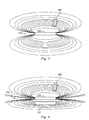
- Fig. 5 shows one example of the transmitter 242 and the implant 202, along with an exemplary flux or electromagnetic field generated by the transmitter 242.
- the transmitter 242 comprises a transmission antenna 250, which in this embodiment, may be a solenoid.
- the implant 202 is captured within the flux volume and can receive energy from the transmitter 242.
- the location of the transmitter 242 on the support structure 240 may be selected to provide the higher levels of flux, at a desired orientation, based on the expected orientation of the implant and the support structure 240.
- the transmitter may be placed on the support structure at a location and orientation that causes electromagnetic flux emission direction to be transverse to the implant antenna 224 when the patient is looking forward, in an expected position. This may maximize the amount of flux captured by the antenna for powering the implant.
- the transmitter length, the permeability of the material the wires are wound on, and the relative position and angle of an implant antenna 224 on the implant 202 to the end of the transmitter 242 all affect the energy transfer efficiency to the implant 202.
- Fig. 5 shows the transmission antenna 250 as a longitudinally extending body.
- the transmission antenna 250 is a cylindrically shaped body extending between a first end and a second end.
- the transmitted magnetic field flux density functions as a torus-shaped field with the transmission antenna 250 on axis. As can seen, considering the shape of the flux field, a large portion of the flux radiated from the transmitter 242 is not available to the implant 202.
- the transmitter 242 in Fig. 6 comprises both the transmission antenna 250 and a flux-shunt 252 that directs the flux from the transmission antenna 250 more towards the implant 202.
- the flux-shunt 252 helps reduce flux transmitted to volumes not occupied by the implant 202. This may improve system electrical efficiency, reduce unintentional emissions, and enable multiple co-located systems to operate together with the least inter-patient RF interference.
- energy transmitted by the transmission antenna 250 that is more directed to the implant 202 may reduce or avoid capture effect by other nearby transponder units that may be on other implants. This may result in better transmission and less degradation that may arise from the implant being embedded in human conductive tissues.
- the flux shunt 252 is disposed adjacent to or in the flux volume generated by the transmission antenna 250 to limit or reduce the flux volume to undesired areas.
- the flux shunt 252 is a low reluctance material disposed on a side of the transmission antenna 250 opposite the implant 202.
- the flux shunt 252 is a longitudinally extending element, having substantially the same length as the transmission antenna, arranged substantially parallel to the transmission antenna 250.
- the low reluctance flux shunt 252 reduces transmission into the unwanted volume surrounding the transmission antenna 250 by collecting most of the local flux and circulating it back to the transmission antenna 250. Since magnetic flux concentrates around the path of least resistance, placement of the low reluctance shunt 252 enables directional flux transmission.
- the flux shunt 252 has a longitudinal length greater than the longitudinal length of the transmission antenna 250. Furthermore, in some embodiments, its shape different than that of the transmission antenna 250. Varying the shape, size, and orientation of the flux shunt 252 relative to the transmission antenna 250 provides directional control over the electromagnetic flux field emitted by the transmission antenna 250. As such, the field can be controlled to most effectively charge the implant in the most efficient manner.
- the flux shunt 252 and the transmission antenna 250 provide more efficient transmission of the electromagnetic flux field to the implant 202 circuitry.
- the flux shunt 252 and transmission antenna 250 are small enough for installation on a wearable support structure 240 such as within an eyeglass design and with a flux field tailored for the application. That is, directing the flux field in a direction where the treatment implant 202 is expected to be located when the support structure 240 is in use. Applying the principles of magnetic circuits, it is possible to recirculate some of the flux in the transmission volume by shunting it back to the transmission antenna 250. Unlike unshunted flux, the re-circulated flux will not propagate to unintended directions.
- this magnetic shunt is low loss, the energy storage element properties of the transmission antenna 250 will be enhanced enabling fewer turns of wire and/or less excitation current to create the minimum required implant operational flux.
- the flux shunting technique can be used to shape the field contour density in three dimensions. Directing the flux using the flux shunt 252 provides improved system electrical efficiency, reduced undesirable radiation, and improved operation.
- the implant 202 includes a transmission device enabling it to broadcast information relating to the implant or the eye condition for consideration. For example, flow rates, pressures, charge status, and other conditions may be broadcast from the implant 202 for consideration by a surgeon or system to provide or achieve a desired treatment.
- a surgeon may implant the ocular implant 202 with its electrically powered treatment element, in the patient's eye to address an ocular condition.
- the implant 202 may draw power for operation from its energy storage element 226.
- the patient may wirelessly charge the energy storage element 226 or provide power to the implant 202 using the external unit 204 by generating an electromagnetic field that encompasses the implant 202.
- Generating the electromagnetic field may be accomplished by directing energy from the power source 244 to the transmission antenna 250, which may be a solenoid.
- the external unit 204 such as the transmitter 242
- a wearable support structure 240 about the face, such as eye-glasses, a cap, or other wearable elements, for example.
- the transmitter 242 may be sized small enough to be comfortably carried on around a user's head and face.
- the location of the transmitter 242 is selected and designed to provide a desired flux volume at the desired orientation to the implant antenna 224.
- the transmitter 242 is then powered to emit the electromagnetic flux field.
- the direction of the electromagnetic field is controlled by locating the shunt 252 at a position within the electromagnetic field at a location opposite the desired transmission direction.
- locating the shunt 252 may include locating the shunt so that the transmission antenna 250 is located in the area between the shunt 252 and the implant 202. As such, the electromagnetic field is stronger in the direction of the implant 202 than in the direction of the flux shunt 252.
- the flux shunting technique may have other applications beyond the intraocular implant. It may also be used with external units differing from the eyeglass temple antenna mount concept. Because ferrites are moldable and machinable on a custom basis, flux shunts may be used to direct flux in many ways and directions in addition to those disclosed herein.
Landscapes
- Health & Medical Sciences (AREA)
- Physics & Mathematics (AREA)
- Ophthalmology & Optometry (AREA)
- General Health & Medical Sciences (AREA)
- Life Sciences & Earth Sciences (AREA)
- Public Health (AREA)
- Heart & Thoracic Surgery (AREA)
- Vascular Medicine (AREA)
- Engineering & Computer Science (AREA)
- Animal Behavior & Ethology (AREA)
- Surgery (AREA)
- Biomedical Technology (AREA)
- Veterinary Medicine (AREA)
- Nuclear Medicine, Radiotherapy & Molecular Imaging (AREA)
- Acoustics & Sound (AREA)
- Otolaryngology (AREA)
- General Physics & Mathematics (AREA)
- Optics & Photonics (AREA)
- Prostheses (AREA)
Claims (10)
- Système (200) pour alimenter un implant oculaire, comprenant :un implant oculaire (202) dimensionné pour être placé dans un oeil, l'implant comprenant :un élément de traitement (216) alimenté électriquement ; etune antenne (224) configurée pour recevoir une énergie pour mettre en oeuvre l'élément de traitement alimenté électriquement ; etun système extérieur portable (204) comprenant :un émetteur (242) dimensionné pour être porté sur la tête du patient ou adjacent à celle-ci pour sa disposition adjacente à l'oeil, l'émetteur étant agencé pour émettre un champ de flux électromagnétique suffisant pour exciter l'antenne et fournir une puissance pour mettre en oeuvre l'élément de traitement alimenté électriquement de l'implant ; etune source de puissance (244) en communication avec l'émetteur et configurée pour fournir une puissance à l'émetteur pour émettre le champ de flux électromagnétique,caractérisé en ce que l'émetteur comprend :une antenne d'émission (250) qui émet le champ de flux électromagnétique ; etun shunt de flux (252) disposé dans le champ de flux électromagnétique conçu pour limiter ou réduire le volume de flux vers des zones indésirables,dans lequel l'antenne d'émission (250) est agencée pour être disposée entre le shunt de flux (252) et l'implant (202).
- Système selon la revendication 1, dans lequel le shunt de flux (252) est réalisé en un matériau à faible reluctance.
- Système selon la revendication 1 ou la revendication 2, dans lequel le shunt de flux est formé de manière cylindrique et a un axe longitudinal s'étendant sensiblement dans la même direction que l'émetteur (242).
- Système selon la revendication 1, dans lequel l'émetteur (242) est configuré de manière à fournir un champ de flux électromagnétique plus intense d'un côté que de l'autre, le champ de flux électromagnétique plus intense étant formé du même côté de l'émetteur que l'implant (202).
- Système selon la revendication 1, dans lequel l'émetteur (242) comprend une antenne d'émission (250) ayant une première extrémité et une deuxième extrémité, l'antenne d'émission étant disposée sur le système extérieur portable de manière à faire face à l'implant (202), l'antenne d'implant (224) étant disposée de manière à être sensiblement transversale à la direction d'émission du champ de flux électromagnétique.
- Système selon la revendication 1, dans lequel l'implant (202) comprend un élément de stockage d'énergie rechargeable (226), l'élément alimenté électriquement (216) étant agencé pour recevoir la puissance de l'élément de stockage d'énergie.
- Système selon la revendication 6, dans lequel l'élément de stockage d'énergie (226) comprend un ensemble d'éléments de stockage agencés en parallèle ou en série.
- Système selon la revendication 1, dans lequel l'élément de traitement alimenté électriquement (216) comprend l'une d'une vanne et d'une pompe.
- Système selon la revendication 1, dans lequel l'implant (202) est dimensionné pour être placé dans une poche sous-conjonctivale (206) de l'oeil.
- Système selon la revendication 1, dans lequel le système extérieur portable (204) comprend l'un de lunettes et d'un chapeau.
Applications Claiming Priority (2)
| Application Number | Priority Date | Filing Date | Title |
|---|---|---|---|
| US13/316,660 US8585664B2 (en) | 2011-12-12 | 2011-12-12 | System and method for powering ocular implants |
| PCT/US2012/068776 WO2013090198A1 (fr) | 2011-12-12 | 2012-12-10 | Système et procédé pour alimenter des implants oculaires |
Publications (2)
| Publication Number | Publication Date |
|---|---|
| EP2768444A1 EP2768444A1 (fr) | 2014-08-27 |
| EP2768444B1 true EP2768444B1 (fr) | 2015-12-09 |
Family
ID=47472049
Family Applications (1)
| Application Number | Title | Priority Date | Filing Date |
|---|---|---|---|
| EP12809447.1A Active EP2768444B1 (fr) | 2011-12-12 | 2012-12-10 | Système et procédé pour alimenter des implants oculaires |
Country Status (8)
| Country | Link |
|---|---|
| US (1) | US8585664B2 (fr) |
| EP (1) | EP2768444B1 (fr) |
| JP (1) | JP2015500709A (fr) |
| CN (1) | CN103987347B (fr) |
| AU (1) | AU2012352543B2 (fr) |
| CA (1) | CA2856736C (fr) |
| ES (1) | ES2557766T3 (fr) |
| WO (1) | WO2013090198A1 (fr) |
Families Citing this family (30)
| Publication number | Priority date | Publication date | Assignee | Title |
|---|---|---|---|---|
| KR20020035476A (ko) | 1999-04-26 | 2002-05-11 | 지엠피 비젼 솔루션즈 인코포레이티드 | 측로 장치 및 녹내장 치료 방법 |
| US6638239B1 (en) | 2000-04-14 | 2003-10-28 | Glaukos Corporation | Apparatus and method for treating glaucoma |
| US7867186B2 (en) | 2002-04-08 | 2011-01-11 | Glaukos Corporation | Devices and methods for treatment of ocular disorders |
| RU2181297C2 (ru) * | 2000-06-20 | 2002-04-20 | Эпштейн Олег Ильич | Способ лечения патологического синдрома и лекарственное средство |
| AU2002258754B2 (en) | 2001-04-07 | 2006-08-17 | Glaukos Corporation | Glaucoma stent and methods thereof for glaucoma treatment |
| US7431710B2 (en) | 2002-04-08 | 2008-10-07 | Glaukos Corporation | Ocular implants with anchors and methods thereof |
| US7331984B2 (en) | 2001-08-28 | 2008-02-19 | Glaukos Corporation | Glaucoma stent for treating glaucoma and methods of use |
| AU2007319383A1 (en) | 2006-11-10 | 2008-05-22 | Glaukos Corporation | Uveoscleral shunt and methods for implanting same |
| EP4193907B1 (fr) | 2011-09-13 | 2026-04-15 | Glaukos Corporation | Capteur physiologique intraoculaire |
| US9173775B2 (en) | 2012-03-26 | 2015-11-03 | Glaukos Corporation | System for delivering multiple ocular implants |
| US9572712B2 (en) | 2012-12-17 | 2017-02-21 | Novartis Ag | Osmotically actuated fluidic valve |
| US9528633B2 (en) | 2012-12-17 | 2016-12-27 | Novartis Ag | MEMS check valve |
| US9295389B2 (en) | 2012-12-17 | 2016-03-29 | Novartis Ag | Systems and methods for priming an intraocular pressure sensor in an intraocular implant |
| US9730638B2 (en) | 2013-03-13 | 2017-08-15 | Glaukos Corporation | Intraocular physiological sensor |
| US10517759B2 (en) | 2013-03-15 | 2019-12-31 | Glaukos Corporation | Glaucoma stent and methods thereof for glaucoma treatment |
| DE102013017837A1 (de) * | 2013-10-07 | 2015-04-09 | Rodenstock Gmbh | Modul(e) zur Verbesserung oder alleinigen Energieversorgung eines am Kopf getragenen elektrischen Gerätes, das auf das Sehfeld des Trägers einwirkt |
| US20150342875A1 (en) | 2014-05-29 | 2015-12-03 | Dose Medical Corporation | Implants with controlled drug delivery features and methods of using same |
| US10117504B2 (en) | 2014-08-09 | 2018-11-06 | Apple Inc. | Wearable band including magnets |
| WO2016025348A1 (fr) | 2014-08-11 | 2016-02-18 | Apple Inc. | Boucle magnétique |
| US9141086B1 (en) | 2014-08-11 | 2015-09-22 | Apple Inc. | Magnetic actuated attachment mechanisms for wearable devices |
| US10123608B2 (en) | 2014-08-11 | 2018-11-13 | Apple Inc. | Wearable band including magnets |
| JP6837475B2 (ja) | 2015-08-14 | 2021-03-03 | イバンティス インコーポレイテッド | 圧力センサを備えた眼用インプラントおよび送達システム |
| WO2017040853A1 (fr) | 2015-09-02 | 2017-03-09 | Glaukos Corporation | Implants d'administration de médicament présentant capacité d'administration bidirectionnelle |
| US10172426B2 (en) | 2015-09-16 | 2019-01-08 | Apple Inc. | Magnetic band clasp |
| CN106073798A (zh) * | 2016-06-01 | 2016-11-09 | 北京理工大学 | 基于植入式和可穿戴生物传感技术的实时健康监测系统 |
| US11116625B2 (en) | 2017-09-28 | 2021-09-14 | Glaukos Corporation | Apparatus and method for controlling placement of intraocular implants |
| CN110367927B (zh) * | 2019-08-01 | 2022-04-08 | 中山大学 | 青光眼眼压连续检测系统及其检测方法 |
| JP2023552087A (ja) * | 2020-11-18 | 2023-12-14 | ブリンク エナジー エルティーディー. | 接眼装置に電力および通信を提供するシステム |
| US20220313491A1 (en) * | 2021-04-02 | 2022-10-06 | Twenty Twenty Therapeutics Llc | Passive intraocular pressure control and associated systems, devices, and methods |
| US20230372151A1 (en) * | 2022-05-20 | 2023-11-23 | Twenty Twenty Therapeutics Llc | Implantable pump for eye disease management |
Family Cites Families (9)
| Publication number | Priority date | Publication date | Assignee | Title |
|---|---|---|---|---|
| JPH1010228A (ja) * | 1996-06-21 | 1998-01-16 | Nabco Ltd | 通行者識別装置 |
| US20050181018A1 (en) * | 2003-09-19 | 2005-08-18 | Peyman Gholam A. | Ocular drug delivery |
| JP4572532B2 (ja) * | 2003-11-20 | 2010-11-04 | セイコーエプソン株式会社 | 電気泳動表示装置及び非接触通信媒体 |
| JP2006319866A (ja) * | 2005-05-16 | 2006-11-24 | Matsushita Electric Ind Co Ltd | アンテナ素子及びそれを用いたループアンテナ並びに無線通信媒体処理装置 |
| AR058947A1 (es) * | 2007-01-08 | 2008-03-05 | Consejo Nac Invest Cient Tec | Microaparato implantable en el ojo para aliviar glaucoma o enfermedad causante de sobrepresion ocular |
| US8721580B2 (en) * | 2009-09-21 | 2014-05-13 | Alcon Research, Ltd. | Power saving glaucoma drainage device |
| US20110071454A1 (en) * | 2009-09-21 | 2011-03-24 | Alcon Research, Ltd. | Power Generator For Glaucoma Drainage Device |
| US20110248671A1 (en) * | 2010-04-08 | 2011-10-13 | Alcon Research, Ltd. | Power System Implantable in Eye |
| CN102258409A (zh) * | 2011-04-20 | 2011-11-30 | 上海交通大学 | 用于视觉假体的无线能量与数据传输系统 |
-
2011
- 2011-12-12 US US13/316,660 patent/US8585664B2/en active Active
-
2012
- 2012-12-10 WO PCT/US2012/068776 patent/WO2013090198A1/fr not_active Ceased
- 2012-12-10 CN CN201280061181.8A patent/CN103987347B/zh not_active Expired - Fee Related
- 2012-12-10 AU AU2012352543A patent/AU2012352543B2/en not_active Ceased
- 2012-12-10 JP JP2014547330A patent/JP2015500709A/ja active Pending
- 2012-12-10 ES ES12809447.1T patent/ES2557766T3/es active Active
- 2012-12-10 EP EP12809447.1A patent/EP2768444B1/fr active Active
- 2012-12-10 CA CA2856736A patent/CA2856736C/fr not_active Expired - Fee Related
Also Published As
| Publication number | Publication date |
|---|---|
| CA2856736C (fr) | 2019-11-26 |
| US8585664B2 (en) | 2013-11-19 |
| ES2557766T3 (es) | 2016-01-28 |
| CN103987347B (zh) | 2016-10-19 |
| AU2012352543B2 (en) | 2016-12-15 |
| US20130150771A1 (en) | 2013-06-13 |
| JP2015500709A (ja) | 2015-01-08 |
| CA2856736A1 (fr) | 2013-06-20 |
| AU2012352543A1 (en) | 2014-06-12 |
| WO2013090198A1 (fr) | 2013-06-20 |
| CN103987347A (zh) | 2014-08-13 |
| EP2768444A1 (fr) | 2014-08-27 |
Similar Documents
| Publication | Publication Date | Title |
|---|---|---|
| AU2012352543B2 (en) | System and method for powering ocular implants | |
| US20110245753A1 (en) | Apparatus and method for lowering intraocular pressure in an eye | |
| US12023497B2 (en) | Stimulus coil and pulse generator for wireless glaucoma therapy | |
| US9603742B2 (en) | Remote magnetic driven flow system | |
| US12161877B2 (en) | Multi-coil wireless power transfer assembly for wireless glaucoma therapy | |
| US8527055B2 (en) | Application of an electrical field in the vicinity of the trabecular meshwork to treat glaucoma | |
| JP2011520524A (ja) | 埋込電子デバイスの誘導充電のためのデバイス | |
| WO2002011648A1 (fr) | Correction refractive par implants musculaires artificiels actifs | |
| ES2983221T3 (es) | Sistema de neuroestimulación | |
| WO2021113486A1 (fr) | Systèmes, dispositifs implantables et procédés de stimulation associée à la vision | |
| US20240350816A1 (en) | Devices with integrated concave coils | |
| US20110022117A1 (en) | Cytokine Production Via Electrical Stimulation to Treat Glaucoma | |
| AU2012245172B2 (en) | Electro-active intraocular lenses | |
| WO2024064971A2 (fr) | Système oculaire à couplage inductif amélioré | |
| HK1184996A (en) | Electro-active intraocular lenses | |
| HK1122719A (en) | Electro-active intraocular lenses |
Legal Events
| Date | Code | Title | Description |
|---|---|---|---|
| PUAI | Public reference made under article 153(3) epc to a published international application that has entered the european phase |
Free format text: ORIGINAL CODE: 0009012 |
|
| 17P | Request for examination filed |
Effective date: 20140522 |
|
| AK | Designated contracting states |
Kind code of ref document: A1 Designated state(s): AL AT BE BG CH CY CZ DE DK EE ES FI FR GB GR HR HU IE IS IT LI LT LU LV MC MK MT NL NO PL PT RO RS SE SI SK SM TR |
|
| RIN1 | Information on inventor provided before grant (corrected) |
Inventor name: DOS SANTOS, CESARIO Inventor name: JENKINS, DANIEL COLLIN |
|
| DAX | Request for extension of the european patent (deleted) | ||
| GRAP | Despatch of communication of intention to grant a patent |
Free format text: ORIGINAL CODE: EPIDOSNIGR1 |
|
| INTG | Intention to grant announced |
Effective date: 20150618 |
|
| GRAS | Grant fee paid |
Free format text: ORIGINAL CODE: EPIDOSNIGR3 |
|
| GRAA | (expected) grant |
Free format text: ORIGINAL CODE: 0009210 |
|
| REG | Reference to a national code |
Ref country code: FR Ref legal event code: PLFP Year of fee payment: 4 |
|
| AK | Designated contracting states |
Kind code of ref document: B1 Designated state(s): AL AT BE BG CH CY CZ DE DK EE ES FI FR GB GR HR HU IE IS IT LI LT LU LV MC MK MT NL NO PL PT RO RS SE SI SK SM TR |
|
| REG | Reference to a national code |
Ref country code: GB Ref legal event code: FG4D |
|
| REG | Reference to a national code |
Ref country code: AT Ref legal event code: REF Ref document number: 764224 Country of ref document: AT Kind code of ref document: T Effective date: 20151215 Ref country code: CH Ref legal event code: EP |
|
| REG | Reference to a national code |
Ref country code: IE Ref legal event code: FG4D |
|
| REG | Reference to a national code |
Ref country code: DE Ref legal event code: R096 Ref document number: 602012013005 Country of ref document: DE |
|
| REG | Reference to a national code |
Ref country code: ES Ref legal event code: FG2A Ref document number: 2557766 Country of ref document: ES Kind code of ref document: T3 Effective date: 20160128 |
|
| REG | Reference to a national code |
Ref country code: LT Ref legal event code: MG4D |
|
| REG | Reference to a national code |
Ref country code: NL Ref legal event code: MP Effective date: 20151209 |
|
| PG25 | Lapsed in a contracting state [announced via postgrant information from national office to epo] |
Ref country code: LT Free format text: LAPSE BECAUSE OF FAILURE TO SUBMIT A TRANSLATION OF THE DESCRIPTION OR TO PAY THE FEE WITHIN THE PRESCRIBED TIME-LIMIT Effective date: 20151209 Ref country code: NO Free format text: LAPSE BECAUSE OF FAILURE TO SUBMIT A TRANSLATION OF THE DESCRIPTION OR TO PAY THE FEE WITHIN THE PRESCRIBED TIME-LIMIT Effective date: 20160309 |
|
| REG | Reference to a national code |
Ref country code: AT Ref legal event code: MK05 Ref document number: 764224 Country of ref document: AT Kind code of ref document: T Effective date: 20151209 |
|
| PG25 | Lapsed in a contracting state [announced via postgrant information from national office to epo] |
Ref country code: SE Free format text: LAPSE BECAUSE OF FAILURE TO SUBMIT A TRANSLATION OF THE DESCRIPTION OR TO PAY THE FEE WITHIN THE PRESCRIBED TIME-LIMIT Effective date: 20151209 Ref country code: RS Free format text: LAPSE BECAUSE OF FAILURE TO SUBMIT A TRANSLATION OF THE DESCRIPTION OR TO PAY THE FEE WITHIN THE PRESCRIBED TIME-LIMIT Effective date: 20151209 Ref country code: BE Free format text: LAPSE BECAUSE OF NON-PAYMENT OF DUE FEES Effective date: 20151231 Ref country code: FI Free format text: LAPSE BECAUSE OF FAILURE TO SUBMIT A TRANSLATION OF THE DESCRIPTION OR TO PAY THE FEE WITHIN THE PRESCRIBED TIME-LIMIT Effective date: 20151209 Ref country code: NL Free format text: LAPSE BECAUSE OF FAILURE TO SUBMIT A TRANSLATION OF THE DESCRIPTION OR TO PAY THE FEE WITHIN THE PRESCRIBED TIME-LIMIT Effective date: 20151209 Ref country code: LV Free format text: LAPSE BECAUSE OF FAILURE TO SUBMIT A TRANSLATION OF THE DESCRIPTION OR TO PAY THE FEE WITHIN THE PRESCRIBED TIME-LIMIT Effective date: 20151209 Ref country code: GR Free format text: LAPSE BECAUSE OF FAILURE TO SUBMIT A TRANSLATION OF THE DESCRIPTION OR TO PAY THE FEE WITHIN THE PRESCRIBED TIME-LIMIT Effective date: 20160310 |
|
| PG25 | Lapsed in a contracting state [announced via postgrant information from national office to epo] |
Ref country code: IS Free format text: LAPSE BECAUSE OF FAILURE TO SUBMIT A TRANSLATION OF THE DESCRIPTION OR TO PAY THE FEE WITHIN THE PRESCRIBED TIME-LIMIT Effective date: 20151209 |
|
| PG25 | Lapsed in a contracting state [announced via postgrant information from national office to epo] |
Ref country code: CZ Free format text: LAPSE BECAUSE OF FAILURE TO SUBMIT A TRANSLATION OF THE DESCRIPTION OR TO PAY THE FEE WITHIN THE PRESCRIBED TIME-LIMIT Effective date: 20151209 |
|
| REG | Reference to a national code |
Ref country code: CH Ref legal event code: PL |
|
| PG25 | Lapsed in a contracting state [announced via postgrant information from national office to epo] |
Ref country code: IS Free format text: LAPSE BECAUSE OF FAILURE TO SUBMIT A TRANSLATION OF THE DESCRIPTION OR TO PAY THE FEE WITHIN THE PRESCRIBED TIME-LIMIT Effective date: 20160409 Ref country code: AT Free format text: LAPSE BECAUSE OF FAILURE TO SUBMIT A TRANSLATION OF THE DESCRIPTION OR TO PAY THE FEE WITHIN THE PRESCRIBED TIME-LIMIT Effective date: 20151209 Ref country code: PT Free format text: LAPSE BECAUSE OF FAILURE TO SUBMIT A TRANSLATION OF THE DESCRIPTION OR TO PAY THE FEE WITHIN THE PRESCRIBED TIME-LIMIT Effective date: 20160411 Ref country code: SK Free format text: LAPSE BECAUSE OF FAILURE TO SUBMIT A TRANSLATION OF THE DESCRIPTION OR TO PAY THE FEE WITHIN THE PRESCRIBED TIME-LIMIT Effective date: 20151209 Ref country code: RO Free format text: LAPSE BECAUSE OF FAILURE TO SUBMIT A TRANSLATION OF THE DESCRIPTION OR TO PAY THE FEE WITHIN THE PRESCRIBED TIME-LIMIT Effective date: 20151209 Ref country code: EE Free format text: LAPSE BECAUSE OF FAILURE TO SUBMIT A TRANSLATION OF THE DESCRIPTION OR TO PAY THE FEE WITHIN THE PRESCRIBED TIME-LIMIT Effective date: 20151209 Ref country code: SM Free format text: LAPSE BECAUSE OF FAILURE TO SUBMIT A TRANSLATION OF THE DESCRIPTION OR TO PAY THE FEE WITHIN THE PRESCRIBED TIME-LIMIT Effective date: 20151209 |
|
| REG | Reference to a national code |
Ref country code: DE Ref legal event code: R097 Ref document number: 602012013005 Country of ref document: DE |
|
| REG | Reference to a national code |
Ref country code: IE Ref legal event code: MM4A |
|
| PG25 | Lapsed in a contracting state [announced via postgrant information from national office to epo] |
Ref country code: MC Free format text: LAPSE BECAUSE OF FAILURE TO SUBMIT A TRANSLATION OF THE DESCRIPTION OR TO PAY THE FEE WITHIN THE PRESCRIBED TIME-LIMIT Effective date: 20151209 |
|
| PLBE | No opposition filed within time limit |
Free format text: ORIGINAL CODE: 0009261 |
|
| STAA | Information on the status of an ep patent application or granted ep patent |
Free format text: STATUS: NO OPPOSITION FILED WITHIN TIME LIMIT |
|
| PG25 | Lapsed in a contracting state [announced via postgrant information from national office to epo] |
Ref country code: DK Free format text: LAPSE BECAUSE OF FAILURE TO SUBMIT A TRANSLATION OF THE DESCRIPTION OR TO PAY THE FEE WITHIN THE PRESCRIBED TIME-LIMIT Effective date: 20151209 Ref country code: PL Free format text: LAPSE BECAUSE OF FAILURE TO SUBMIT A TRANSLATION OF THE DESCRIPTION OR TO PAY THE FEE WITHIN THE PRESCRIBED TIME-LIMIT Effective date: 20151209 Ref country code: CH Free format text: LAPSE BECAUSE OF NON-PAYMENT OF DUE FEES Effective date: 20151231 Ref country code: LI Free format text: LAPSE BECAUSE OF NON-PAYMENT OF DUE FEES Effective date: 20151231 Ref country code: IE Free format text: LAPSE BECAUSE OF NON-PAYMENT OF DUE FEES Effective date: 20151210 |
|
| 26N | No opposition filed |
Effective date: 20160912 |
|
| REG | Reference to a national code |
Ref country code: FR Ref legal event code: PLFP Year of fee payment: 5 |
|
| PG25 | Lapsed in a contracting state [announced via postgrant information from national office to epo] |
Ref country code: SI Free format text: LAPSE BECAUSE OF FAILURE TO SUBMIT A TRANSLATION OF THE DESCRIPTION OR TO PAY THE FEE WITHIN THE PRESCRIBED TIME-LIMIT Effective date: 20151209 |
|
| PG25 | Lapsed in a contracting state [announced via postgrant information from national office to epo] |
Ref country code: BE Free format text: LAPSE BECAUSE OF FAILURE TO SUBMIT A TRANSLATION OF THE DESCRIPTION OR TO PAY THE FEE WITHIN THE PRESCRIBED TIME-LIMIT Effective date: 20151209 |
|
| PG25 | Lapsed in a contracting state [announced via postgrant information from national office to epo] |
Ref country code: HU Free format text: LAPSE BECAUSE OF FAILURE TO SUBMIT A TRANSLATION OF THE DESCRIPTION OR TO PAY THE FEE WITHIN THE PRESCRIBED TIME-LIMIT; INVALID AB INITIO Effective date: 20121210 Ref country code: BG Free format text: LAPSE BECAUSE OF FAILURE TO SUBMIT A TRANSLATION OF THE DESCRIPTION OR TO PAY THE FEE WITHIN THE PRESCRIBED TIME-LIMIT Effective date: 20151209 |
|
| PG25 | Lapsed in a contracting state [announced via postgrant information from national office to epo] |
Ref country code: CY Free format text: LAPSE BECAUSE OF FAILURE TO SUBMIT A TRANSLATION OF THE DESCRIPTION OR TO PAY THE FEE WITHIN THE PRESCRIBED TIME-LIMIT Effective date: 20151209 |
|
| PG25 | Lapsed in a contracting state [announced via postgrant information from national office to epo] |
Ref country code: HR Free format text: LAPSE BECAUSE OF FAILURE TO SUBMIT A TRANSLATION OF THE DESCRIPTION OR TO PAY THE FEE WITHIN THE PRESCRIBED TIME-LIMIT Effective date: 20151209 |
|
| PG25 | Lapsed in a contracting state [announced via postgrant information from national office to epo] |
Ref country code: MT Free format text: LAPSE BECAUSE OF FAILURE TO SUBMIT A TRANSLATION OF THE DESCRIPTION OR TO PAY THE FEE WITHIN THE PRESCRIBED TIME-LIMIT Effective date: 20151209 |
|
| REG | Reference to a national code |
Ref country code: FR Ref legal event code: PLFP Year of fee payment: 6 |
|
| PG25 | Lapsed in a contracting state [announced via postgrant information from national office to epo] |
Ref country code: LU Free format text: LAPSE BECAUSE OF NON-PAYMENT OF DUE FEES Effective date: 20151210 |
|
| PG25 | Lapsed in a contracting state [announced via postgrant information from national office to epo] |
Ref country code: MK Free format text: LAPSE BECAUSE OF FAILURE TO SUBMIT A TRANSLATION OF THE DESCRIPTION OR TO PAY THE FEE WITHIN THE PRESCRIBED TIME-LIMIT Effective date: 20151209 |
|
| PG25 | Lapsed in a contracting state [announced via postgrant information from national office to epo] |
Ref country code: TR Free format text: LAPSE BECAUSE OF FAILURE TO SUBMIT A TRANSLATION OF THE DESCRIPTION OR TO PAY THE FEE WITHIN THE PRESCRIBED TIME-LIMIT Effective date: 20151209 Ref country code: AL Free format text: LAPSE BECAUSE OF FAILURE TO SUBMIT A TRANSLATION OF THE DESCRIPTION OR TO PAY THE FEE WITHIN THE PRESCRIBED TIME-LIMIT Effective date: 20151209 |
|
| PGFP | Annual fee paid to national office [announced via postgrant information from national office to epo] |
Ref country code: ES Payment date: 20190102 Year of fee payment: 7 |
|
| REG | Reference to a national code |
Ref country code: GB Ref legal event code: 732E Free format text: REGISTERED BETWEEN 20200109 AND 20200115 |
|
| REG | Reference to a national code |
Ref country code: GB Ref legal event code: 732E Free format text: REGISTERED BETWEEN 20200116 AND 20200122 |
|
| PGFP | Annual fee paid to national office [announced via postgrant information from national office to epo] |
Ref country code: IT Payment date: 20191209 Year of fee payment: 8 |
|
| REG | Reference to a national code |
Ref country code: DE Ref legal event code: R082 Ref document number: 602012013005 Country of ref document: DE Representative=s name: K & H BONAPAT PATENTANWAELTE KOCH VON BEHREN &, DE Ref country code: DE Ref legal event code: R081 Ref document number: 602012013005 Country of ref document: DE Owner name: ALCON INC., CH Free format text: FORMER OWNER: ALCON RESEARCH, LTD., 76134-2099 FORT WORTH, TEXAS, US |
|
| REG | Reference to a national code |
Ref country code: ES Ref legal event code: PC2A Owner name: ALCON INC. Effective date: 20200407 |
|
| REG | Reference to a national code |
Ref country code: ES Ref legal event code: FD2A Effective date: 20210601 |
|
| PG25 | Lapsed in a contracting state [announced via postgrant information from national office to epo] |
Ref country code: ES Free format text: LAPSE BECAUSE OF NON-PAYMENT OF DUE FEES Effective date: 20191211 |
|
| PG25 | Lapsed in a contracting state [announced via postgrant information from national office to epo] |
Ref country code: IT Free format text: LAPSE BECAUSE OF NON-PAYMENT OF DUE FEES Effective date: 20201210 |
|
| P01 | Opt-out of the competence of the unified patent court (upc) registered |
Effective date: 20230505 |
|
| PGFP | Annual fee paid to national office [announced via postgrant information from national office to epo] |
Ref country code: DE Payment date: 20251119 Year of fee payment: 14 |
|
| PGFP | Annual fee paid to national office [announced via postgrant information from national office to epo] |
Ref country code: GB Payment date: 20251120 Year of fee payment: 14 |
|
| PGFP | Annual fee paid to national office [announced via postgrant information from national office to epo] |
Ref country code: FR Payment date: 20251124 Year of fee payment: 14 |