EP2768683B1 - Drehbare welle mit einer fluidleitung - Google Patents
Drehbare welle mit einer fluidleitung Download PDFInfo
- Publication number
- EP2768683B1 EP2768683B1 EP12777881.9A EP12777881A EP2768683B1 EP 2768683 B1 EP2768683 B1 EP 2768683B1 EP 12777881 A EP12777881 A EP 12777881A EP 2768683 B1 EP2768683 B1 EP 2768683B1
- Authority
- EP
- European Patent Office
- Prior art keywords
- pipe
- shaft
- axle
- fluid duct
- rotatable shaft
- Prior art date
- Legal status (The legal status is an assumption and is not a legal conclusion. Google has not performed a legal analysis and makes no representation as to the accuracy of the status listed.)
- Active
Links
Images






Classifications
-
- B—PERFORMING OPERATIONS; TRANSPORTING
- B60—VEHICLES IN GENERAL
- B60C—VEHICLE TYRES; TYRE INFLATION; TYRE CHANGING; CONNECTING VALVES TO INFLATABLE ELASTIC BODIES IN GENERAL; DEVICES OR ARRANGEMENTS RELATED TO TYRES
- B60C23/00—Devices for measuring, signalling, controlling, or distributing tyre pressure or temperature, specially adapted for mounting on vehicles; Arrangement of tyre inflating devices on vehicles, e.g. of pumps or of tanks; Tyre cooling arrangements
- B60C23/001—Devices for manually or automatically controlling or distributing tyre pressure whilst the vehicle is moving
- B60C23/003—Devices for manually or automatically controlling or distributing tyre pressure whilst the vehicle is moving comprising rotational joints between vehicle-mounted pressure sources and the tyres
- B60C23/00309—Devices for manually or automatically controlling or distributing tyre pressure whilst the vehicle is moving comprising rotational joints between vehicle-mounted pressure sources and the tyres characterised by the location of the components, e.g. valves, sealings, conduits or sensors
- B60C23/00336—Devices for manually or automatically controlling or distributing tyre pressure whilst the vehicle is moving comprising rotational joints between vehicle-mounted pressure sources and the tyres characterised by the location of the components, e.g. valves, sealings, conduits or sensors on the axles
-
- B—PERFORMING OPERATIONS; TRANSPORTING
- B60—VEHICLES IN GENERAL
- B60C—VEHICLE TYRES; TYRE INFLATION; TYRE CHANGING; CONNECTING VALVES TO INFLATABLE ELASTIC BODIES IN GENERAL; DEVICES OR ARRANGEMENTS RELATED TO TYRES
- B60C23/00—Devices for measuring, signalling, controlling, or distributing tyre pressure or temperature, specially adapted for mounting on vehicles; Arrangement of tyre inflating devices on vehicles, e.g. of pumps or of tanks; Tyre cooling arrangements
- B60C23/001—Devices for manually or automatically controlling or distributing tyre pressure whilst the vehicle is moving
- B60C23/003—Devices for manually or automatically controlling or distributing tyre pressure whilst the vehicle is moving comprising rotational joints between vehicle-mounted pressure sources and the tyres
- B60C23/00345—Details of the rotational joints
-
- B—PERFORMING OPERATIONS; TRANSPORTING
- B60—VEHICLES IN GENERAL
- B60C—VEHICLE TYRES; TYRE INFLATION; TYRE CHANGING; CONNECTING VALVES TO INFLATABLE ELASTIC BODIES IN GENERAL; DEVICES OR ARRANGEMENTS RELATED TO TYRES
- B60C23/00—Devices for measuring, signalling, controlling, or distributing tyre pressure or temperature, specially adapted for mounting on vehicles; Arrangement of tyre inflating devices on vehicles, e.g. of pumps or of tanks; Tyre cooling arrangements
- B60C23/001—Devices for manually or automatically controlling or distributing tyre pressure whilst the vehicle is moving
- B60C23/003—Devices for manually or automatically controlling or distributing tyre pressure whilst the vehicle is moving comprising rotational joints between vehicle-mounted pressure sources and the tyres
- B60C23/00381—Devices for manually or automatically controlling or distributing tyre pressure whilst the vehicle is moving comprising rotational joints between vehicle-mounted pressure sources and the tyres specially adapted for steerable wheels
Definitions
- This invention relates to a tyre pressure arrangement on a vehicle. More specifically the invention relates to a tyre pressure arrangement on an agricultural machine or vehicle.
- tyre pressure When driving on the road, at a higher speed, comparatively high tyre pressure is desirable, as a tyre with high pressure has more stability than a tyre with lower pressure and wear of the tyre is reduced. This is particularly the case when driving around bends at high speed.
- a tyre inflation and deflation arrangement comprises at least one rotary passage which is provided on or within an axle which carries air to and away from the tyres.
- the rotary passage may be connected to a further air duct for carrying air.
- the rotary passage extends between rigid, stationary parts which are connected to the vehicle frame or form a part of it, (for example an axle housing) and rotating parts, for example, the wheel hubs.
- rigid, stationary parts which are connected to the vehicle frame or form a part of it, (for example an axle housing) and rotating parts, for example, the wheel hubs.
- the air may be transmitted axially along an axial rotary passage parallel to the vehicle axle.
- Axial rotary passages are described in the applicant's previous patent application WO2012/045533 .
- Axial rotary passages are mainly used for retrofit solutions as no changes of axle components are required. However, additional space is required outside the axle housing where the passages are mounted.
- Radial rotary passage arrangements require changes in most of the main axle components (both the housing and shaft). The design of such arrangements demand detailed knowledge of the load to be supported and the dimensions of the axle components. Radial rotary passage arrangements are described in the applicant's previous patent applications WO2012/084912 , WO2012/084690 , and WO2012/045533 . Such arrangements are used within the rear axle housing of a tractor so that no space outside of the axle housing is required.
- One advantage of this arrangement is that the rotary passage is situated in an area which is dust-protected by the axle housing and that the ducts which transfer air from the rotary passages to the tyre can be integrated into the axle housings and axle shafts thus reducing costs considerably.
- the sealing assembly for the rotary passage is situated between the two bearings of the axle shaft.
- Air is conveyed in two separate ducts lying parallel to the rotational axis of the axle, one for supply of interior of tyre during inflation (supply line), another one for pneumatic activation of a valve on the wheel for tyre deflation (control line).
- the ducts are connected to two radial passages in the axle shaft each of which extend at right angles from the ducts to the axle housing.
- the two ducts extend along two bores which are drilled in the axle shaft parallel to the rotational axis of the axle shaft offset to each other. The bores and the ducts impair the stability of the axle shaft considerably due to the two ducts being offset of the rotational axis.
- the front axle consists of pivotable final drives which are coupled with each other via an axle block.
- This kind of steerable axle can also be found mounted on other agricultural machines, for example combine harvesters or forage harvesters, at the rear of the vehicle. Owing to the small distance between the bearings of these kinds of final drives, the arrangement as described in WO2012/084412 is disadvantageous for the following reasons:
- a rotatable shaft comprising a fluid duct characterised in that the fluid duct extends through a single bore in the shaft and said fluid duct is provided with at least two chambers each extending axially along at least a part of the length of the single bore.
- a part of the fluid duct is arranged co-axially of the rotational axis, or parallel to the rotational axis of the shaft, thus helping to keep the shaft balanced.
- the fluid duct comprises a pipe.
- the pipe is provided with an interior pipe part which together with the pipe forms at least two chambers.
- the rotatable shaft may be a vehicle axle, such as a steerable axle. Further, the shaft may be a sun wheel of a planetary drive housed in the axle.
- the shaft is provided with a rotary passage which extends perpendicularly from the duct to an axle housing. More preferably one rotary passage is provided between a steering knuckle housing and the sun wheel and a second rotary passage is provided between the sun wheel and a planetary carrier.
- One chamber of the duct carries pressurised air for inflating a tyre and another chamber carries pressurised air for operating a valve to deflate the tyre.
- the rotary passages are preferably provided with at least one aeration hole.
- the fluid duct is centred in the planetary carrier by a ball bearing.
- Figure 1 shows a cross sectional view of a first final drive 1 for a steerable axle, such as a front tractor axle (not shown).
- Line X shown in figure 1 represents an axle to which the first final drive is pivotably attached.
- a second final drive is mounted symmetrically on the other side of the vehicle axle X and can be rotated around an axle X via a bearing which is not shown.
- the arrangement of these final drives is known technology and therefore only a summarised explanation is provided. Since both final drives function in the same manner, reference in this description is made only to the first final drive.
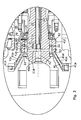
- FIGS. 2 , 3 and 5 to 7 are enlarged drawings of figure 1 .
- the final drive 1 consists mainly of a steering knuckle housing 10 which carries a major part of the wheel load and is shown in figure 1 in two-part execution with a steering knuckle housing part 11 and an upper support plate 12.
- the steering knuckle housing 10 is pivotable around axle X.
- the associated swivel bearings are not shown, as they are already known from the state of the art.
- the sun wheel 21 of the planetary drive is rotatably mounted to rotate around rotational axis Z.
- a ball bearing 13 is provided which is secured axially along the sun wheel 21 by means of retainer ring 14.
- the sun wheel 21 is driveably connected with a front axle power train which in turn is coupled by means of an adjustment mechanism to a combustion engine for transmission of its drive torque.
- the planetary drive in the final drive 1 serves to change the speed of the fast-moving sun wheel into a slower speed of the wheel hub 38. This works as follows:
- the planetary wheels 30 are enclosed by a ring gear 32, comprising a ring gear rim 33 and a ring gear carrier 34 connected by gear tooth formations 33a, 34a.
- the ring gear carrier is secured by bolts 35 to the steering knuckle housing part 11, thus making sure that the ring gear 32 does not rotate.
- the planetary wheels 30 are meshed with the gearing 36a which is meshed with the gearing 33b on the interior side of the ring gear rim 33. When the sun wheel is driven the planetary wheel 30 mounted on the planetary carrier 36 is rotated about axis X.
- the planetary carrier 36 is rotated about axis Z and the individual planetary wheels 30 circle around axis Z on a circular path, turning about axis Y.
- the planetary carrier 36 forms a housing around the planetary gear train 30 and interior components and is connected in a torque-proof way by bolts (not shown) to wheel hub 38 which is rotatably mounted on the steering knuckle housing part 11 and rotates about axis Z.
- wheel hub 38 is equipped with wheel bolts 39 which help to mount the tyres on the wheel hub 38.
- an air transfer unit 41 is screwed together with steering knuckle housing part 11.
- the air transfer unit 41 has on a side facing the centre of the vehicle two compressed air connections 41 a and 41 b.
- Compressed air connection 41 a has a wider diameter and is connected to a supply line which supplies the tyre with air during inflation and the compressed air connection 41 b is connected to a control line which activates a valve for deflation of the tyre.
- air transfer unit 41 comprises a first part 41 e and a second part 41f fitted together at joint 41 g to enable simple machining of the ducts 41 c, 41 d.
- the fitting together of the two parts 41e and 41f can be implemented by means of soldering, screwing etc.
- the air transfer part can be a one-piece-unit.
- the described ducts 41c, 41 d may then, for example, be implemented via a lost-core process in a cast iron part.
- the duct 41 d ends in the first ring-shaped transfer chamber 48.
- gaskets are mounted which seal the transfer chamber 48 in direction of the sealing area 21 c of the sun wheel 21.
- the gaskets 49a, 49b are equipped with lip seals which are not illustrated in detail here but which are pressed against the sealing area 21c of sun wheel to provide a seal when the transfer chamber 48 is pressurised. When pressure decreases to ambient pressure, the lip seals retract to their original position and are no longer in contact with sealing area 21 c.
- the sealing arrangement On one side of the gasket 49d in an outwards direction the sealing arrangement is completed by means of a spacer disc 79. On the other side of the gasket 49d a shaft sealing ring 51 is provided for protection against dirt and dust. Between the two gaskets 49b and 49c there is a retainer ring 80, positioned axially of the shaft.
- the sealing arrangement 47 has radial aeration ducts 52 which are connected via the annular gap between the sun wheel 21 and the air transfer unit 41 to ambient air.
- Bore 42 serves mainly for mounting fluid pipe 53 which forms the fluid duct in the final drives 1.
- the bore 42 may itself be used to form the fluid duct with a pipe part.
- Figures 4a to 4h show different views of the fluid pipe 53.
- Figure 4a is a perspective view of the pipe 53.
- Figures 4b is a plan view of the pipe.
- Figure 4c is a horizontal section along line A-A of figure 4a .
- Figure 4d is vertical cross section along line B-B of figure 4b .
- Figure 4e is a section along line C-C of figure 4d.
- Figure 4f is a cross section along line E-E of figure 4d
- figure 4g is a cross sectional view of figure 4d along line F-F
- figure 4h is a cross sectional view of figure 4d along line G-G.
- Fluid pipe 53 comprises a wall 54 and interior pipe part 55.
- the wall 54 has a constant inner diameter and has at its first end 54a graduations 54b und 54c which are described further on.
- the interior pipe part 55 has a rounded H shape in cross section as can be seen in figures 4f, 4g and 8 .
- Pipe 53 has at its first end an axial hole 55a which is connected with a first passage 55b.
- a second passage 55c is situated below the first passage 55b (as seen in Figures 4d, 4f, 4g 4h ) with pipe part 55 forming a wall 55d between the two passages 55b and 55c.
- a threaded hole is provided to allow the pipe 53 to be removed from bore 42.
- the wall 54 has radial drill holes having different radii. At its first end 54a the wall 54 has a small radial drill hole 54e, which only penetrates a lower part of wall 54. At the other end of pipe53 there is a radial drill hole 54f which has about the same diameter as drill hole 54e which penetrates the wall completely. An additional, larger radial drill hole 54 g penetrates only an upper part of the wall 54.
- Wall 54 and interior pipe part 55 are provided with several circumferential grooves for the mounting of gaskets etc, which will be explained in detail later.
- Wall 54 and interior pipe part 55 are connected by means of two solder rings 56 at both ends and a press fit.
- the press fit is in this case only executed over a length of 4-5mm to facilitate mounting.
- Axial drill hole 55a, first passage 55b and radial drill hole 54g form the first chamber 53a with an enlarged cross section for connection to the supply line.
- Radial drill hole 54e, second passage 55c and radial drill hole 54f form a second chamber 53b with a smaller cross section for connection with the control line.
- an additional solder connection 56b in a longitudinal direction is provided, between the two solder rings 56a.
- the solder connection 56b is prepared by inserting a soldering string or soldering paste in a longitudinal groove and then heating it together with the soldering rings 56a in a soldering furnace.
- a soldering gap of about 0.5 mm is made and soldering material penetrates the gap and forms a sealing and twist-proof connection.
- a torsion-locking device 57 is also soldered to the exterior pipe 54 with another soldering ring 56 and prevents twisting of the pipe 53 in the mounting hole of sun wheel 21 as will be explained later.
- FIG. 5 shows the connection of the pipe 53 to the sun wheel 21.
- the sun wheel has a co-axial, graduated mounting bore 42, which is executed as a through hole.
- the pipe 53 is fixed in the first gradation 22a of the mounting bore 42 by sliding it in position
- the supply line and the control line are connected to the first rotary passage 47 and then radial drill holes 11d and 11e to the centre axle of the sun wheel and through the mounting bore 42.
- Pipe 53 provides separate chambers which serve for routing of the two air flows.
- the radial drill hole 11 d (for supply line) is connected to the pipe 53 in the mounting bore 42 and is fluidically connected with the first chamber 53a of pipe 53.
- a closing plug 58 closes the mounting bore 42 facing the interior of the vehicle so that no air can leak to the outside.
- the radial drill holes 11 e (for the control line) are joined with the pipe 53 in the mounting bore 42, and a second gradation 22b is provided at this joint. Due to the larger inner diameter of the second gradation 22b in comparison with the exterior diameter of the gradations 54b of the wall 54 a ring chamber 59 is formed which is sealed by the O-rings 60 on both sides to make sure no leakage can occur. Through this ring chamber 59 radial drill hole 11 e is fluidically connected to the second chamber 53b of pipe 53.
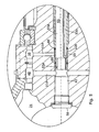
- Figure 6 illustrates a part of the pipe 53 and the transfer of air in the slower moving part of the final drive 1 which is the planetary carrier 36 and thus the wheel hub 38.
- a plug-in sleeve 43 is mounted on planetary carrier 36 in a torque-proof way by means of a sliding fit which will be explained in detail later.
- Plug-in sleeve 43 and bearing sleeve 44 are similar to the two parts of the pipe 53, and are connected in a twist-proof manner and sealed by means of a soldering connection to provide separate cavities to guide air.
- bearing sleeve 44 has several functions:
- the second passage arrangement 61 is similar to the first rotary passage arrangement 47. Details of the second passage arrangement 61 are described in figure 7 .
- the second rotary passage arrangement 61 is mounted via bearing sleeve 44. Due to the poor wear resistance of the wall 54 of the pipe 53 a grinded and hardened wear sleeve 83 is mounted on the pipe 53 in a torque proof way. Wear sleeve 83 and the inner race of combined bearing 45 are axially secured by circlip 46c.
- the second rotary passage arrangement 61 further comprises a shaft seal 71, mounted at the interior side for interior oil sealing, and four more gaskets 72a, 72b, 72c and 72d, that are mounted in a torque proof manner in bearing sleeve 44 and are sealed off against wear sleeve.
- the gaskets 72a, 72b, 72c and 72d are provided with lip seals not illustrated in detail which are pressed against the sealing surface 70a of the wear sleeve 70 in case of increasing pressure and thus provide sealing.
- Shaft seal 71 and gaskets 72a, 72b, 72c and 72d are secured axially by means of circlips 73. Similar to the rotary passage arrangement 47 two separate transfer chambers 74 and 75 are formed.
- the transfer chamber 74 is fluidically connected to the first chamber 53a of the pipe 53 via the drill hole 54g and also connected to a corresponding co-axial drill hole 70b in the wear sleeve 70 and thus assigned to the supply line.
- the transfer chamber 74 ends in a radial drill hole 44b in the bearing sleeve 44.
- a pipe 76 leads through plug-in sleeve 43 by means of a corresponding hole 43a and is fixed by soldering.
- the planetary carrier 36 is provided with a radial groove 36a. In this groove the pipe 76 is located and leads to a connection unit which is connected to the tyre interior.
- the transfer chamber 75 is connected fluidically with the second chamber 53b of the pipe 53 via the drill hole 54f and a corresponding co-axial hole 70c in the wear sleeve 70 and thus assigned to the control line.
- the transfer chamber 75 leads to a radial drill hole 44c and a groove 44d in the bearing sleeve 44.
- the groove 44d leads to a radial drill hole 43b in the plug-in sleeve 43, into which again a pipe 77 is soldered.
- a radial groove 36b is provided through which pipe 77 extends.
- Pipe 77 leads to a connecting unit which is connected to a pneumatic control valve mounted on the wheel rim.
- Pipes 76 and 77 positioned in radial grooves 36a and 36b ensure position of plug-in sleeves 43 in relation to the planetary carrier 36.
- the seal rings 84 are provided to avoid leakage.
- a cover 78 locks the second sealing arrangement 61 and any installed equipment after mounting. By biasing the respective screws to fix cover 78, snap ring 82 is axially pressed against plug-in sleeve 43 and thereby also bearing sleeve 44 ensuring no pivot movement in relation to planetary carrier 36.
- torsion-locking device 57 of pipe 53 locally engages with a mating contour 44g in the form of a longitudinal groove in bearing sleeve 44 to ensure that that sun wheel 21 and pipe 53 rotate together.
- the second sealing arrangement 61 is provided with a vent in accordance with the applicant's previous patent application, WO2012/084690 .
- a vent in accordance with the applicant's previous patent application, WO2012/084690 .
- the cover 78 has a small hole 78a. With this hole air is transported to the outside so that the sealing arrangement grants safe function.
- the two separate chambers 53a and 53b are formed by a pipe wall 54 and an interior pipe part 55.
- the interior pipe part 55 has two passages55b, 55c milled in a longitudinal direction.
- Figure 10 shows an alternative embodiment of a fluid duct.
- the fluid duct 62 comprises a pipe 63 and an interior pipe part 64, whereas the interior pipe part 64 is positioned co-axially by a centering sleeve 65 and a connector 66.
- the two sleeves 65, 66 are connected in a torque-proof way via soldering rings 68 and press-fits with the pipe 63.
- the two sleeves 65, 66 provide co-axial support for the interior pipe part 64 in the corresponding mounting holes 65a, 66a. Due to this arrangement two separate chambers are formed for the routing of fluid, such as air.
- the pipe interior 64a, radial drill hole 66b in the connector 66 and a first radial drill hole 63a in the pipe 63 form in this case a first chamber 62a with a smaller cross section for connection with the control line.
- a second radial drill hole 63b, ring chamber 63c (formed between the exterior diameter of the interior pipe part 64 and the interior diameter of the pipe 63) and a third radial drill hole 63d, as well as radial drill hole 54f form a second chamber 62b with a larger cross section for connection to the supply line.
- both chambers 62a and 62b have to be sealed against each other, one further soldering ring 69 is provided.
- a torsion locking protection 67 is also soldered to the pipe 63 with a soldering ring.
- FIGS 11 and 12 show a rotational shaft of a rear axle 2a in accordance with the invention.
- the same references have been used for those features which are the same as those mentioned previously.
- the rear axle has an outer trumpet housing 2 within which a drive shaft 3 is supported by bearings 4.
- Drive shaft 3 terminates in a hub flange 5 to which a wheel disc carrying a wheel rim of a tyre is attached.
- a contact means 15 surrounds annular zones where pipes 18, 19 connect to shaft 3 and are sealed to shaft 3 by seals 17.
- This contact means is formed from or coated with a plastics material such as PTFE. Alternatively, the contact means could be made from stainless steel, or could be hardened by nitrogen to resist wear. Passages 8 and 9 emerge through contact means 15 in the vicinity of the inner ends of pipes 18 and 19.
- a first sealing means 15a seals the inner end of pipe 18 to the contact means 15 and a second sealing means 15b seals the inner end of pipe 19 to this contact means 15.
- Shaft 3 is provided with a graduated mounting bore 91 in which pipe 94 is mounted to form a fluid duct 93.
- One end of mounting bore 91 is connected to radial drill holes 11 d and 11 e which extend through shaft 3 and which are connected to passages 8 and 9 situated in pipes 18 and 19 which extend through housing 2.
- Pipes 18 and 19 are provided with pipe fittings 18a and 19a which connect passages 8 and 9 to a control and a supply line respectively.
- the other end of pipe 94 extends through hub flange 5 where it is connected to supply and control lines (not shown).
- the supply line is connected to the tyre and the control line is connected to a valve connected to the supply line.
- the fluid duct 93 comprises a pipe 94 and an interior pipe part 95.
- the interior pipe part 95 is positioned co-axially by two concentric sleeves 96 and a connector 97.
- the two sleeves 96 and connector 97 are connected to exterior pipe 94 and an interior pipe part 95 in a torque-proof way by soldering.
- the two sleeves 96 provide co-axial support for the interior pipe part 95 in the corresponding mounting holes 96a. Due to this arrangement two separate chambers are formed for the routing of air.
- the pipe interior 95a forms in this case a first chamber 93a with a smaller cross section for connection with the control line.
- Interior pipe part 95 extends through sleeve 96 at the side of the hub flange 5 and is equipped with a thread 95b which is used to attach a hose connection which is connected to the valve.
- a first radial drill hole 94a, ring chamber 93b (formed between the exterior diameter of the interior pipe part 95 and the interior diameter of the exterior pipe 94), a second radial drill hole 94b and radial threaded hole 97a in connector 97 form a second chamber 93b with a larger cross section for connection with the supply line.
- Radial threaded hole 97a in connector 97 is used to attach a hose connection which is connected to the tyre.
- Radial drill hole 11d is connected to chamber 93a of the pipe 94 and radial drill hole 11 e is connected to chamber 93b.
- soldering connection between the pipe 94, interior pipe part 95, centring sleeve 96 and connector 97 is similar to air routing pipe 63 shown in Figure 10 , the soldering connection is not shown here for clarity.
- the fluid duct 93 is connected to the shaft 3 by press-fit between a first gradation 91 a and the outer diameter of pipe 94 and a second gradation 91 b and mating surface 97b in connector 97.
- a screw connection along dotted line 98 may be provided for additional axial securing.
- Figure 13 shows a further, simplified embodiment of a rotational shaft in a non-steerable axle with reference to Figure 12 .
- Most of the components are the same as previously described.
- a graduated mounting bore 99 of figure 13 in shaft 3 has a different shape which is explained later on.
- fluid duct 100 comprises a pipe 101 and a connector 102 wherein the pipe 101 is positioned co-axially by connector 102 on one side.
- Pipe 101 and a connector 102 are connected by soldering.
- the pipe interior 101 a forms in this case a first chamber 100a with a smaller cross section for connection with the control line.
- Pipe 101 extends through connector 102 at the side of the hub flange 5 and is equipped with a thread 101 b which is used to attach a hose connection which is connected to the valve.
- a ring chamber 100b (formed between the exterior diameter of the interior pipe 101 and the interior diameter mounting bore 99), a axial drill hole 102a and radial threaded hole 102b in connector 102 form a second chamber 100b with a larger cross section for connection with the supply line.
- Radial threaded hole 102b in connector 102 is used to attach a hose connection which is connected to the tyre.
- a screw connection along dotted line 103 may be provided for additional axial securing.
- Radial drill hole 11 d is connected to chamber 100a of the fluid duct 100 and radial drill hole 11 e is connected to chamber 100b.
- An additional seal 104 is provided to seal the interior pipe 101 to the mating contour in mounting bore 99 of shaft 3.
- the pipe 101 is equipped with a contour, a so called cutting edge, which is deformed when the fluid duct 100 is screwed into shaft 3 and thereby provides sealing.
- parts of the fluid ducts 53, 62, 93,100 are connected by means of soldering. Due to the low level of pressure in the TPCU the parts may also be fixed by gluing. Other known methods of joining may also be used. One more possibility would be to manufacture the fluid duct by a casting process, in which interior cavities may for example be poured over lost cores.
- FIG. 11 to 13 are also applicable in a steering axle design not having a planetary drive installed in the final drive.
- a shaft similar to sun wheel 21 may directly engage with a torque transmitting part similar to the planetary carrier 36 (by gearing) which is connected to the wheel hub 38 without presence of a planetary drive 20.
- This design is very common for vehicles where the final reduction to wheel speed is provided in the driveline before the final drive.
Landscapes
- Engineering & Computer Science (AREA)
- Mechanical Engineering (AREA)
- Arrangement Or Mounting Of Propulsion Units For Vehicles (AREA)
Claims (8)
- Drehbare Welle (21), mit einer sich durch eine einzelne Bohrung (42) in der Welle erstreckenden Fluidleitung, wobei die Fluidleitung mit mindestens zwei sich axial entlang mindestens eines Teils der Länge der einzelnen Bohrung erstreckenden Kammern versehen ist, dadurch gekennzeichnet, dass die Fluidleitung ein äußeres Rohr (53, 54) und ein inneres Rohr (53, 55) aufweist, die gemeinsam mindestens zwei Kammern (53a, 53b) bilden.
- Drehbare Welle (21) nach Anspruch 1, wobei ein Teil der Fluidleitung koaxial zu der Drehachse der Welle (21) oder parallel zu der Drehachse (Z) der Welle (21) angeordnet ist.
- Drehbare Welle (21) nach einem der vorhergehenden Ansprüche, wobei die drehbare Welle Teil einer Fahrzeugachse ist.
- Drehbare Welle (21) nach Anspruch 3, wobei die Achse eine lenkbare Achse ist.
- Drehbare Welle (21) nach Anspruch 4, wobei die Welle (21) ein Sonnenrad eines Planetengetriebes in einer Achse ist.
- Drehbare Welle (21) nach Anspruch 3 oder 4 oder 5, wobei die Welle mit einem drehbaren Durchlass (47, 61) versehen ist, der sich senkrecht von der Leitung zu einem Achsgehäuse erstreckt.
- Drehbare Welle (21) nach Anspruch 6, wobei ein erster drehbarer Durchlass (47) zwischen einem Achsschenkelgehäuse (11) und dem Sonnenrad (21) und ein zweiter drehbarer Durchlass (61) zwischen dem Sonnenrad und einem Planetenträger vorgesehen ist.
- Drehbare Welle (21) nach Anspruch 7, wobei die Fluidleitung mittels eines Kugellagers in dem Planetenträger (36) montiert und zentriert ist.
Applications Claiming Priority (2)
| Application Number | Priority Date | Filing Date | Title |
|---|---|---|---|
| GBGB1118156.7A GB201118156D0 (en) | 2011-10-21 | 2011-10-21 | Rotatable shaft comprising fluid duct |
| PCT/EP2012/069707 WO2013056988A1 (en) | 2011-10-21 | 2012-10-05 | Rotatable shaft comprising a fluid duct |
Publications (2)
| Publication Number | Publication Date |
|---|---|
| EP2768683A1 EP2768683A1 (de) | 2014-08-27 |
| EP2768683B1 true EP2768683B1 (de) | 2015-12-16 |
Family
ID=45220029
Family Applications (1)
| Application Number | Title | Priority Date | Filing Date |
|---|---|---|---|
| EP12777881.9A Active EP2768683B1 (de) | 2011-10-21 | 2012-10-05 | Drehbare welle mit einer fluidleitung |
Country Status (3)
| Country | Link |
|---|---|
| EP (1) | EP2768683B1 (de) |
| GB (1) | GB201118156D0 (de) |
| WO (1) | WO2013056988A1 (de) |
Families Citing this family (10)
| Publication number | Priority date | Publication date | Assignee | Title |
|---|---|---|---|---|
| DE102014003597A1 (de) * | 2014-03-17 | 2015-09-17 | Voss Normalien Gmbh & Co. Kg | Drehdurchführung mit Gelenkwelle |
| US9457624B2 (en) | 2014-10-22 | 2016-10-04 | Deere & Company | Variable tread axle assembly for tire inflation system |
| US10473206B2 (en) | 2015-07-02 | 2019-11-12 | Deere & Company | Transmission vent |
| US10807413B2 (en) * | 2017-02-02 | 2020-10-20 | Dana Heavy Vehicle Systems Group, Llc | Front axle wheel assembly and the tire inflation system made therewith |
| FR3068300B1 (fr) * | 2017-06-30 | 2019-08-16 | Poclain Hydraulics Industrie | Appareil hydraulique ameliore comprenant une conduite pour la circulation d'air |
| US11226040B2 (en) | 2019-10-31 | 2022-01-18 | Deere & Company | Rotary seal apparatus and arrangement of a rotary seal apparatus in an axle support system |
| IT202000024172A1 (it) * | 2020-10-14 | 2022-04-14 | Cnh Ind Italia Spa | Mozzo ruota di un veicolo agricolo o da lavoro |
| GB202211397D0 (en) | 2022-08-04 | 2022-09-21 | Agco Int Gmbh | Rotary feedthrough arrangement |
| DE102023206643A1 (de) * | 2023-07-13 | 2025-01-16 | Zf Friedrichshafen Ag | Reifendruckregelvorrichtung, landwirtschaftliches Nutzfahrzeug und Baumaschine |
| US20260048619A1 (en) * | 2024-08-14 | 2026-02-19 | Arvinmeritor Technology, Llc | Fluid Conduit for Use in a Tire Inflation System |
Family Cites Families (8)
| Publication number | Priority date | Publication date | Assignee | Title |
|---|---|---|---|---|
| GB191311748A (en) * | 1913-05-20 | 1913-12-18 | Attilio Del Mastro | Improvements in Means for Inflating Pneumatic Tyres. |
| FR2373404A1 (fr) * | 1976-12-07 | 1978-07-07 | Verdy Robert | Dispositif d'egalisation des charges entre deux pneumatiques de roues porteuses |
| DE3127646A1 (de) * | 1981-07-13 | 1983-04-14 | Daimler-Benz Ag, 7000 Stuttgart | "zentral durch die radnabe eines kraftfahrzeuges gelegte luftfuehrung fuer eine reifendruckregelanlage" |
| JP4296436B2 (ja) * | 2006-01-19 | 2009-07-15 | トヨタ自動車株式会社 | タイヤ空気圧導入装置 |
| EP2625049A1 (de) | 2010-10-04 | 2013-08-14 | AGCO International GmbH | Drehüberträger |
| GB201021931D0 (en) | 2010-12-23 | 2011-02-02 | Agco Int Gmbh | Rotary seal arrangement |
| GB201021928D0 (en) | 2010-12-23 | 2011-02-02 | Agco Internat Ltd | Tyre inflation |
| GB201021929D0 (en) | 2010-12-23 | 2011-02-02 | Agco Internat Ltd | Tyre inflation |
-
2011
- 2011-10-21 GB GBGB1118156.7A patent/GB201118156D0/en not_active Ceased
-
2012
- 2012-10-05 WO PCT/EP2012/069707 patent/WO2013056988A1/en not_active Ceased
- 2012-10-05 EP EP12777881.9A patent/EP2768683B1/de active Active
Also Published As
| Publication number | Publication date |
|---|---|
| EP2768683A1 (de) | 2014-08-27 |
| WO2013056988A9 (en) | 2013-06-06 |
| GB201118156D0 (en) | 2011-11-30 |
| WO2013056988A1 (en) | 2013-04-25 |
Similar Documents
| Publication | Publication Date | Title |
|---|---|---|
| EP2768683B1 (de) | Drehbare welle mit einer fluidleitung | |
| US6325123B1 (en) | Tire inflation system for a steering knuckle wheel end | |
| AU2017219115B2 (en) | Coupled compound planetary transmission for a wheel unit | |
| CN104507715B (zh) | 中央轮胎充气系统旋转空气接头组件 | |
| US6283186B1 (en) | Tire inflation system for live spindle wheel end | |
| CN103282655B (zh) | 用于轮胎充气系统的具有中心阀的旋转空气连接件 | |
| US7185688B2 (en) | Central tire inflation system for drive axle | |
| US10792995B2 (en) | In-wheel motor drive device | |
| EP3144161B1 (de) | Radendanordnung für reifenfüllsystem | |
| US20180222258A1 (en) | Steer axle tire inflation system | |
| US20090266198A1 (en) | Laser welded differential casings for vehicle axles | |
| US10471782B2 (en) | Steer axle tire inflation system | |
| CA1105536A (en) | Power shaft support bearing | |
| US20190273412A1 (en) | In-wheel motor drive device and connection structure between in-wheel motor drive device and wheel | |
| US7534172B2 (en) | Direct torque flow constant velocity joint having a non-rotating boot | |
| CA1070248A (en) | Planetary steering hub assembly | |
| EP4032727B1 (de) | Radendanordnung mit ringförmiger nabenkammer | |
| RU154956U1 (ru) | Колесный узел с устройством подвода воздуха к шине | |
| US8327895B2 (en) | Drive axle seal body and tire inflation system | |
| US10675965B2 (en) | In-wheel motor driving device | |
| RU113697U1 (ru) | Устройство подвода воздуха к шинам транспортного средства | |
| CN100447446C (zh) | 用于动力传动装置的连接结构与连接方法 | |
| JP2006088809A (ja) | タイヤの空気圧調節装置を備えた車輪用回転支持装置 | |
| US20250346076A1 (en) | Track widener for inflating/deflating tyres of a vehicle | |
| CN115157926B (zh) | 一种车桥终端驱动装置、安装方法及矿用自卸车 |
Legal Events
| Date | Code | Title | Description |
|---|---|---|---|
| PUAI | Public reference made under article 153(3) epc to a published international application that has entered the european phase |
Free format text: ORIGINAL CODE: 0009012 |
|
| 17P | Request for examination filed |
Effective date: 20140521 |
|
| AK | Designated contracting states |
Kind code of ref document: A1 Designated state(s): AL AT BE BG CH CY CZ DE DK EE ES FI FR GB GR HR HU IE IS IT LI LT LU LV MC MK MT NL NO PL PT RO RS SE SI SK SM TR |
|
| DAX | Request for extension of the european patent (deleted) | ||
| GRAP | Despatch of communication of intention to grant a patent |
Free format text: ORIGINAL CODE: EPIDOSNIGR1 |
|
| INTG | Intention to grant announced |
Effective date: 20150901 |
|
| GRAS | Grant fee paid |
Free format text: ORIGINAL CODE: EPIDOSNIGR3 |
|
| GRAA | (expected) grant |
Free format text: ORIGINAL CODE: 0009210 |
|
| AK | Designated contracting states |
Kind code of ref document: B1 Designated state(s): AL AT BE BG CH CY CZ DE DK EE ES FI FR GB GR HR HU IE IS IT LI LT LU LV MC MK MT NL NO PL PT RO RS SE SI SK SM TR |
|
| REG | Reference to a national code |
Ref country code: GB Ref legal event code: FG4D |
|
| REG | Reference to a national code |
Ref country code: CH Ref legal event code: EP |
|
| REG | Reference to a national code |
Ref country code: IE Ref legal event code: FG4D |
|
| REG | Reference to a national code |
Ref country code: AT Ref legal event code: REF Ref document number: 765383 Country of ref document: AT Kind code of ref document: T Effective date: 20160115 |
|
| REG | Reference to a national code |
Ref country code: DE Ref legal event code: R096 Ref document number: 602012013204 Country of ref document: DE |
|
| REG | Reference to a national code |
Ref country code: NL Ref legal event code: MP Effective date: 20151216 |
|
| REG | Reference to a national code |
Ref country code: LT Ref legal event code: MG4D |
|
| PG25 | Lapsed in a contracting state [announced via postgrant information from national office to epo] |
Ref country code: NO Free format text: LAPSE BECAUSE OF FAILURE TO SUBMIT A TRANSLATION OF THE DESCRIPTION OR TO PAY THE FEE WITHIN THE PRESCRIBED TIME-LIMIT Effective date: 20160316 Ref country code: LT Free format text: LAPSE BECAUSE OF FAILURE TO SUBMIT A TRANSLATION OF THE DESCRIPTION OR TO PAY THE FEE WITHIN THE PRESCRIBED TIME-LIMIT Effective date: 20151216 Ref country code: HR Free format text: LAPSE BECAUSE OF FAILURE TO SUBMIT A TRANSLATION OF THE DESCRIPTION OR TO PAY THE FEE WITHIN THE PRESCRIBED TIME-LIMIT Effective date: 20151216 |
|
| REG | Reference to a national code |
Ref country code: AT Ref legal event code: MK05 Ref document number: 765383 Country of ref document: AT Kind code of ref document: T Effective date: 20151216 |
|
| PG25 | Lapsed in a contracting state [announced via postgrant information from national office to epo] |
Ref country code: SE Free format text: LAPSE BECAUSE OF FAILURE TO SUBMIT A TRANSLATION OF THE DESCRIPTION OR TO PAY THE FEE WITHIN THE PRESCRIBED TIME-LIMIT Effective date: 20151216 Ref country code: RS Free format text: LAPSE BECAUSE OF FAILURE TO SUBMIT A TRANSLATION OF THE DESCRIPTION OR TO PAY THE FEE WITHIN THE PRESCRIBED TIME-LIMIT Effective date: 20151216 Ref country code: GR Free format text: LAPSE BECAUSE OF FAILURE TO SUBMIT A TRANSLATION OF THE DESCRIPTION OR TO PAY THE FEE WITHIN THE PRESCRIBED TIME-LIMIT Effective date: 20160317 Ref country code: FI Free format text: LAPSE BECAUSE OF FAILURE TO SUBMIT A TRANSLATION OF THE DESCRIPTION OR TO PAY THE FEE WITHIN THE PRESCRIBED TIME-LIMIT Effective date: 20151216 Ref country code: LV Free format text: LAPSE BECAUSE OF FAILURE TO SUBMIT A TRANSLATION OF THE DESCRIPTION OR TO PAY THE FEE WITHIN THE PRESCRIBED TIME-LIMIT Effective date: 20151216 Ref country code: NL Free format text: LAPSE BECAUSE OF FAILURE TO SUBMIT A TRANSLATION OF THE DESCRIPTION OR TO PAY THE FEE WITHIN THE PRESCRIBED TIME-LIMIT Effective date: 20151216 |
|
| PG25 | Lapsed in a contracting state [announced via postgrant information from national office to epo] |
Ref country code: ES Free format text: LAPSE BECAUSE OF FAILURE TO SUBMIT A TRANSLATION OF THE DESCRIPTION OR TO PAY THE FEE WITHIN THE PRESCRIBED TIME-LIMIT Effective date: 20151216 Ref country code: IT Free format text: LAPSE BECAUSE OF FAILURE TO SUBMIT A TRANSLATION OF THE DESCRIPTION OR TO PAY THE FEE WITHIN THE PRESCRIBED TIME-LIMIT Effective date: 20151216 Ref country code: CZ Free format text: LAPSE BECAUSE OF FAILURE TO SUBMIT A TRANSLATION OF THE DESCRIPTION OR TO PAY THE FEE WITHIN THE PRESCRIBED TIME-LIMIT Effective date: 20151216 |
|
| PG25 | Lapsed in a contracting state [announced via postgrant information from national office to epo] |
Ref country code: RO Free format text: LAPSE BECAUSE OF FAILURE TO SUBMIT A TRANSLATION OF THE DESCRIPTION OR TO PAY THE FEE WITHIN THE PRESCRIBED TIME-LIMIT Effective date: 20151216 Ref country code: IS Free format text: LAPSE BECAUSE OF FAILURE TO SUBMIT A TRANSLATION OF THE DESCRIPTION OR TO PAY THE FEE WITHIN THE PRESCRIBED TIME-LIMIT Effective date: 20160416 Ref country code: EE Free format text: LAPSE BECAUSE OF FAILURE TO SUBMIT A TRANSLATION OF THE DESCRIPTION OR TO PAY THE FEE WITHIN THE PRESCRIBED TIME-LIMIT Effective date: 20151216 Ref country code: PT Free format text: LAPSE BECAUSE OF FAILURE TO SUBMIT A TRANSLATION OF THE DESCRIPTION OR TO PAY THE FEE WITHIN THE PRESCRIBED TIME-LIMIT Effective date: 20160418 Ref country code: SK Free format text: LAPSE BECAUSE OF FAILURE TO SUBMIT A TRANSLATION OF THE DESCRIPTION OR TO PAY THE FEE WITHIN THE PRESCRIBED TIME-LIMIT Effective date: 20151216 Ref country code: AT Free format text: LAPSE BECAUSE OF FAILURE TO SUBMIT A TRANSLATION OF THE DESCRIPTION OR TO PAY THE FEE WITHIN THE PRESCRIBED TIME-LIMIT Effective date: 20151216 Ref country code: SM Free format text: LAPSE BECAUSE OF FAILURE TO SUBMIT A TRANSLATION OF THE DESCRIPTION OR TO PAY THE FEE WITHIN THE PRESCRIBED TIME-LIMIT Effective date: 20151216 |
|
| REG | Reference to a national code |
Ref country code: DE Ref legal event code: R097 Ref document number: 602012013204 Country of ref document: DE |
|
| REG | Reference to a national code |
Ref country code: FR Ref legal event code: PLFP Year of fee payment: 5 |
|
| PLBE | No opposition filed within time limit |
Free format text: ORIGINAL CODE: 0009261 |
|
| STAA | Information on the status of an ep patent application or granted ep patent |
Free format text: STATUS: NO OPPOSITION FILED WITHIN TIME LIMIT |
|
| PG25 | Lapsed in a contracting state [announced via postgrant information from national office to epo] |
Ref country code: PL Free format text: LAPSE BECAUSE OF FAILURE TO SUBMIT A TRANSLATION OF THE DESCRIPTION OR TO PAY THE FEE WITHIN THE PRESCRIBED TIME-LIMIT Effective date: 20151216 Ref country code: DK Free format text: LAPSE BECAUSE OF FAILURE TO SUBMIT A TRANSLATION OF THE DESCRIPTION OR TO PAY THE FEE WITHIN THE PRESCRIBED TIME-LIMIT Effective date: 20151216 |
|
| 26N | No opposition filed |
Effective date: 20160919 |
|
| PG25 | Lapsed in a contracting state [announced via postgrant information from national office to epo] |
Ref country code: BE Free format text: LAPSE BECAUSE OF FAILURE TO SUBMIT A TRANSLATION OF THE DESCRIPTION OR TO PAY THE FEE WITHIN THE PRESCRIBED TIME-LIMIT Effective date: 20151216 |
|
| PG25 | Lapsed in a contracting state [announced via postgrant information from national office to epo] |
Ref country code: SI Free format text: LAPSE BECAUSE OF FAILURE TO SUBMIT A TRANSLATION OF THE DESCRIPTION OR TO PAY THE FEE WITHIN THE PRESCRIBED TIME-LIMIT Effective date: 20151216 |
|
| REG | Reference to a national code |
Ref country code: CH Ref legal event code: PL |
|
| GBPC | Gb: european patent ceased through non-payment of renewal fee |
Effective date: 20161005 |
|
| REG | Reference to a national code |
Ref country code: IE Ref legal event code: MM4A |
|
| PG25 | Lapsed in a contracting state [announced via postgrant information from national office to epo] |
Ref country code: GB Free format text: LAPSE BECAUSE OF NON-PAYMENT OF DUE FEES Effective date: 20161005 Ref country code: CH Free format text: LAPSE BECAUSE OF NON-PAYMENT OF DUE FEES Effective date: 20161031 Ref country code: LI Free format text: LAPSE BECAUSE OF NON-PAYMENT OF DUE FEES Effective date: 20161031 |
|
| PG25 | Lapsed in a contracting state [announced via postgrant information from national office to epo] |
Ref country code: LU Free format text: LAPSE BECAUSE OF NON-PAYMENT OF DUE FEES Effective date: 20161005 |
|
| REG | Reference to a national code |
Ref country code: FR Ref legal event code: PLFP Year of fee payment: 6 |
|
| PG25 | Lapsed in a contracting state [announced via postgrant information from national office to epo] |
Ref country code: IE Free format text: LAPSE BECAUSE OF NON-PAYMENT OF DUE FEES Effective date: 20161005 |
|
| PG25 | Lapsed in a contracting state [announced via postgrant information from national office to epo] |
Ref country code: HU Free format text: LAPSE BECAUSE OF FAILURE TO SUBMIT A TRANSLATION OF THE DESCRIPTION OR TO PAY THE FEE WITHIN THE PRESCRIBED TIME-LIMIT; INVALID AB INITIO Effective date: 20121005 |
|
| PG25 | Lapsed in a contracting state [announced via postgrant information from national office to epo] |
Ref country code: MC Free format text: LAPSE BECAUSE OF FAILURE TO SUBMIT A TRANSLATION OF THE DESCRIPTION OR TO PAY THE FEE WITHIN THE PRESCRIBED TIME-LIMIT Effective date: 20151216 Ref country code: MT Free format text: LAPSE BECAUSE OF NON-PAYMENT OF DUE FEES Effective date: 20161031 Ref country code: MK Free format text: LAPSE BECAUSE OF FAILURE TO SUBMIT A TRANSLATION OF THE DESCRIPTION OR TO PAY THE FEE WITHIN THE PRESCRIBED TIME-LIMIT Effective date: 20151216 Ref country code: CY Free format text: LAPSE BECAUSE OF FAILURE TO SUBMIT A TRANSLATION OF THE DESCRIPTION OR TO PAY THE FEE WITHIN THE PRESCRIBED TIME-LIMIT Effective date: 20151216 |
|
| PG25 | Lapsed in a contracting state [announced via postgrant information from national office to epo] |
Ref country code: BG Free format text: LAPSE BECAUSE OF FAILURE TO SUBMIT A TRANSLATION OF THE DESCRIPTION OR TO PAY THE FEE WITHIN THE PRESCRIBED TIME-LIMIT Effective date: 20151216 |
|
| REG | Reference to a national code |
Ref country code: FR Ref legal event code: PLFP Year of fee payment: 7 |
|
| PG25 | Lapsed in a contracting state [announced via postgrant information from national office to epo] |
Ref country code: TR Free format text: LAPSE BECAUSE OF FAILURE TO SUBMIT A TRANSLATION OF THE DESCRIPTION OR TO PAY THE FEE WITHIN THE PRESCRIBED TIME-LIMIT Effective date: 20151216 Ref country code: AL Free format text: LAPSE BECAUSE OF FAILURE TO SUBMIT A TRANSLATION OF THE DESCRIPTION OR TO PAY THE FEE WITHIN THE PRESCRIBED TIME-LIMIT Effective date: 20151216 |
|
| P01 | Opt-out of the competence of the unified patent court (upc) registered |
Effective date: 20230518 |
|
| REG | Reference to a national code |
Ref country code: DE Ref legal event code: R084 Ref document number: 602012013204 Country of ref document: DE |
|
| PGFP | Annual fee paid to national office [announced via postgrant information from national office to epo] |
Ref country code: DE Payment date: 20251021 Year of fee payment: 14 |
|
| PGFP | Annual fee paid to national office [announced via postgrant information from national office to epo] |
Ref country code: FR Payment date: 20251030 Year of fee payment: 14 |