EP2768687B1 - Halterung für einen fahrzeugtank - Google Patents
Halterung für einen fahrzeugtank Download PDFInfo
- Publication number
- EP2768687B1 EP2768687B1 EP12841988.4A EP12841988A EP2768687B1 EP 2768687 B1 EP2768687 B1 EP 2768687B1 EP 12841988 A EP12841988 A EP 12841988A EP 2768687 B1 EP2768687 B1 EP 2768687B1
- Authority
- EP
- European Patent Office
- Prior art keywords
- elements
- bracket
- tank
- stop
- bracket according
- Prior art date
- Legal status (The legal status is an assumption and is not a legal conclusion. Google has not performed a legal analysis and makes no representation as to the accuracy of the status listed.)
- Active
Links
Images
Classifications
-
- B—PERFORMING OPERATIONS; TRANSPORTING
- B60—VEHICLES IN GENERAL
- B60K—ARRANGEMENT OR MOUNTING OF PROPULSION UNITS OR OF TRANSMISSIONS IN VEHICLES; ARRANGEMENT OR MOUNTING OF PLURAL DIVERSE PRIME-MOVERS IN VEHICLES; AUXILIARY DRIVES FOR VEHICLES; INSTRUMENTATION OR DASHBOARDS FOR VEHICLES; ARRANGEMENTS IN CONNECTION WITH COOLING, AIR INTAKE, GAS EXHAUST OR FUEL SUPPLY OF PROPULSION UNITS IN VEHICLES
- B60K15/00—Arrangement in connection with fuel supply of combustion engines or other fuel consuming energy converters, e.g. fuel cells; Mounting or construction of fuel tanks
- B60K15/03—Fuel tanks
- B60K15/063—Arrangement of tanks
- B60K15/067—Mounting of tanks
-
- B—PERFORMING OPERATIONS; TRANSPORTING
- B60—VEHICLES IN GENERAL
- B60K—ARRANGEMENT OR MOUNTING OF PROPULSION UNITS OR OF TRANSMISSIONS IN VEHICLES; ARRANGEMENT OR MOUNTING OF PLURAL DIVERSE PRIME-MOVERS IN VEHICLES; AUXILIARY DRIVES FOR VEHICLES; INSTRUMENTATION OR DASHBOARDS FOR VEHICLES; ARRANGEMENTS IN CONNECTION WITH COOLING, AIR INTAKE, GAS EXHAUST OR FUEL SUPPLY OF PROPULSION UNITS IN VEHICLES
- B60K15/00—Arrangement in connection with fuel supply of combustion engines or other fuel consuming energy converters, e.g. fuel cells; Mounting or construction of fuel tanks
- B60K15/03—Fuel tanks
- B60K15/063—Arrangement of tanks
- B60K2015/0636—Arrangement of tanks the fuel tank being part of the chassis or frame
-
- B—PERFORMING OPERATIONS; TRANSPORTING
- B60—VEHICLES IN GENERAL
- B60Y—INDEXING SCHEME RELATING TO ASPECTS CROSS-CUTTING VEHICLE TECHNOLOGY
- B60Y2200/00—Type of vehicle
- B60Y2200/10—Road Vehicles
- B60Y2200/14—Trucks; Load vehicles, Busses
Definitions
- the invention relates to a bracket for a vehicle tank. It relates also to a vehicle provided with a bracket.
- brackets of this kind are usually provided with a strap which extends round the tank and has a threaded connection by which it is tightened relative to the bracket. If however the tank is made not of metal but of more flexible material, e.g. polymer material, as is for example often the case of reducing agent tanks for combustion engines, there is risk that the clamping force of the strap may over time become insufficient, with the result that the preload force in the threaded connection is lost. In the case of brackets with straps it may also be difficult to fit and remove the tank, particularly in regions where there is limited space sideways.
- WO98/10959 describes a railing bracket having two clamping jaws and reciprocally displacing using a screw.
- An object of the present invention is therefore to propose a bracket of the kind indicated in the introduction which can reliably keep a tank made of any material fastened and maintain preload in the threaded connection.
- Another object is to propose a bracket which makes the tank to easy to fit to and remove from.
- the fact that the elements are movable along one another towards a stop means that the tank can be clamped with suitable clamping force between the jaws when the elements reach the stop. Thereafter the threaded connection may be tightened with suitable preload against the stop independently of the clamping force between the jaws and the tank, so that this preload is absorbed by the bracket and not, as in a screw clamp, by the tank.
- the invention thus results in no risk of the threaded connection losing its preload if the tank yields to the clamping force between the jaws.
- the bracket has two rail elements movable along one another makes it easy to take apart and put together from below, e.g. from the underside of a vehicle frame, with the result that the tank need not be first moved sideways for it to be released.
- the tank may therefore be situated in a readily accessible location, e.g. at the inside of a frame member of a freight vehicle, leaving the outside clear for fitting other vehicle components.
- the stop comprises one of the crosspieces, obviating the need for any separate stop on either of the rails. In this context there is however nothing to bar the possibility of the stop comprising both of the crosspieces.
- a side edge of the rail element which engages with the stop runs obliquely in a direction of movement between the elements.
- the oblique side edge effects clamping of the elements sideways against one another when the threaded connection is tightened. More specifically, mutually facing side surfaces of the elements are then clamped against one another when the threaded connection is tightened, so that the stop comprises also one of these side surfaces and the elements are wedged firmly to one another. Sideways gaps between the elements may thus be avoided. If both of the elements have such oblique edge surfaces, the mutually facing side surfaces can be wedged firmly against one another at both of the mutually inserted ends of the elements.
- the rail elements may have a substantially U-shaped cross-section.
- the threaded connection may then extend in the continuous duct formed between the rails and be accessible to screwing tools from the nearer lower and also the upper end of the duct if so required.
- Mutually opposite flanges of the rail elements may have apertures to accommodate the crosspieces. Such apertures may then also be dimensioned to allow the crosspieces to be inserted in them from outside the bracket.
- the apertures may have oblique edge surfaces. If for example the apertures in at least one of the rail elements have oblique edge surfaces, adjoining crosspieces, which also engage with an oblique edge surface of the other rail element, may then distribute the force from the threaded connection more equally to the two rail elements.
- Each crosspiece may have said stops at its opposite ends and a thickened middle portion with a hole for a screw of the threaded connection.
- the ends may then be circular cylindrical spigots which can be set freely against the engaging oblique edge surfaces when the threaded connection is tightened, without affecting the force distribution in the elements.
- the rail elements may also have reinforcements at the oblique edge surfaces.
- Such reinforcements may be in the form of pieces of sheetmetal welded on locally to the edge surfaces to reduce the local stresses in the rail elements.
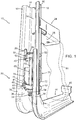
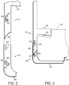
- a bracket according to the invention has a pair of rail elements 10 and 30 which each have a jaw 24 and 44 respectively for supporting and clamping a tank 80 between them.
- bracket often refers only to the in this case lower jaw 44, it is here used inclusively for the whole arrangement.
- the rail elements 10, 30 in the embodiment example depicted are made of sheet steel with mutually complementary substantially U-shaped cross-sectional profiles so that the lower element 30 can be accommodated slidingly in the upper element 10.
- the upper rail element 10 is provided with a bottom flange 14, a pair of mutually opposite side flanges 16 perpendicular to the bottom flange, and a pair of outer flanges 18 parallel with the bottom flange.
- the lower rail element 30 is similarly provided with a bottom flange 34, a pair of mutually opposite side flanges 36 perpendicular to the bottom flange, and a pair of outer flanges 38 parallel with the bottom flange.
- each crosspiece 50 In each rail element 10, 30 there is a crosspiece 50.
- each crosspiece may take the form of a machined part, it is made in the embodiment example by a forging process for good strength.
- Each crosspiece has a thickened middle portion 54 with a hole 56 and a pair of mutually opposite end spigots 52.
- the end spigots 52 of the upper crosspiece are accommodated in mutually opposite apertures 20 in the upper rail element 10, and the end spigots 52 of the lower crosspiece are similarly accommodated in mutually opposite apertures 40 in the lower rail element 30.
- the shape and size of the apertures 20, 40 may be such as to allow the crosspieces 50 to be inserted from outside the rail elements.
- a threaded connection 60 ( FIG. 1 ) with a screw 62 and a nut 64 extends through the holes 56 in the crosspieces 50 in order to draw the rail elements 10, 30 together and thereby clamp the tank between the jaws 24, 44.
- the arrangement is such that when the tank 80 is sufficiently clamped between the jaws, at least one of the crosspieces, e.g. the upper crosspiece, serves as a stop to prevent further moving together of the rail elements. More specifically, a pair of edge surfaces 42 of the lower element 30 then come into contact with the upper crosspiece's end spigots 52, which thus serve as a stop to prevent further upward movement of the lower element. The threaded connection 60 may then be tightened with appropriate preload against this stop.
- edge surfaces 42 are also oblique in one direction so that they clamp or wedge the elements 10, 30 against one another at the upper end of the lower element 30 when the threaded connection 60 is tightened against the upper stop 52.
- the lower crosspiece 50 likewise serves as a similar stop whereby oblique edge surfaces 22 of the upper element 10 wedge the elements 10, 30 against one another at the lower end of the upper element when the threaded connection 60 is tightened against the lower stop 52.
- the apertures 40 in the lower element 30 may also have an oblique edge surface 41.
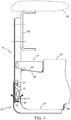
- the forces acting upon the elements 10, 30 may then be distributed more equally, as represented by the force arrows in FIG. 4 .
- the resulting bending force in the bracket from the weight of the tank 80 may then be absorbed by the rail elements 10, 30 without the screw 60 being subject to bending loads.
- FIG. 1 illustrates also the possibility of strengthening the elements 10, 30 in the regions of engagement with the crosspieces 50.
- the upper element 10 is connected, e.g. by plug welding, to a pair of outer reinforcements 70 which each have an oblique edge surface 72 (only one of them depicted in FIGS. 1 and 4 ) complementing the oblique edge surfaces 22.
- the lower element 30 may then likewise be similarly connected, e.g. by plug welding, to in this case an inner U-shaped reinforcement 74 with a pair of oblique edge surfaces 76 (only one of them depicted in FIG. 1 ) complementing the oblique edge surfaces 41 of the apertures 40.
- FIG. 4 depicts a tank 80 fitted to a frame member 92 of a not further depicted freight vehicle 90 by means of a bracket according to the invention.
- the upper jaw 24 which clamps the tank 80 to the lower jaw 44 has with advantage a oblique underside 25 which by wedge action prevents the tank from moving out from the bracket.
- the lower jaw 44 may have an end section 45 which is bent upwards to a shape which holds the tank 80 to the bracket.
Landscapes
- Engineering & Computer Science (AREA)
- Life Sciences & Earth Sciences (AREA)
- Sustainable Development (AREA)
- Sustainable Energy (AREA)
- Chemical & Material Sciences (AREA)
- Combustion & Propulsion (AREA)
- Transportation (AREA)
- Mechanical Engineering (AREA)
- Cooling, Air Intake And Gas Exhaust, And Fuel Tank Arrangements In Propulsion Units (AREA)
- Clamps And Clips (AREA)
Claims (8)
- Halterung für einen Fahrzeugtank, gekennzeichnet
durch ein Paar von Schienenelementen (10, 30), die jeweils eine Klemmbacke (24, 44) umfassen, wobei die Klemmbacken (24, 44) dazu eingerichtet sind, einen Fahrzeugtank zwischen ihnen zu lagern und zu klemmen, wobei die Schienenelemente (10, 30) aneinander gegen einen Anschlag (52) bewegbar sind, und
durch eine Gewindeverbindung (60), die zwischen Stegen (50) des entsprechenden Elements zum Klemmen des Tanks (80) zwischen die Klemmbacken wirkt, wenn sie gegen den Anschlag (52) festgezogen wird, wobei eine Randfläche (42, 22, 72) des Schienenelements (10, 30), das mit dem Anschlag (52) in Eingriff steht, in einer Bewegungsrichtung zwischen den Schienenelementen (10, 30) schräg positioniert ist. - Halterung nach Anspruch 1, wobei der Anschlag (52) einen der Stege (50) umfasst.
- Halterung nach einem der vorhergehenden Ansprüche, wobei die Schienenelemente (10, 30) einen im Wesentlichen U-förmigen Querschnitt aufweisen.
- Halterung nach einem der vorhergehenden Ansprüche, wobei einander gegenüberliegende Flanken (16, 36) der Schienenelemente (10, 30) Öffnungen (20, 40) aufweisen, um die Stege (50) aufzunehmen.
- Halterung nach Anspruch 4, wobei die Öffnungen (40) schräge Randflächen (41) umfassen.
- Halterung nach einem der vorhergehenden Ansprüche, wobei jeder Steg (50) die Anschläge (52) an dessen gegenüberliegenden Enden und einen verdickten Mittelabschnitt (54) mit einer Öffnung (56) für eine Schraube (62) der Gewindeverbindung (60) aufweist.
- Halterung nach Anspruch 5, wobei die Schienenelemente (10, 30) Verstärkungen (70, 72, 74, 76) auf den schrägen Randflächen (22, 41) aufweisen.
- Fahrzeug (90) ausgestattet mit einer Halterung nach einem der vorhergehenden Ansprüche.
Applications Claiming Priority (2)
| Application Number | Priority Date | Filing Date | Title |
|---|---|---|---|
| SE1150970A SE536130C2 (sv) | 2011-10-20 | 2011-10-20 | Konsol för en fordonstank |
| PCT/SE2012/051076 WO2013058699A1 (en) | 2011-10-20 | 2012-10-09 | Bracket for a vehicle tank |
Publications (3)
| Publication Number | Publication Date |
|---|---|
| EP2768687A1 EP2768687A1 (de) | 2014-08-27 |
| EP2768687A4 EP2768687A4 (de) | 2017-04-12 |
| EP2768687B1 true EP2768687B1 (de) | 2019-06-05 |
Family
ID=48141169
Family Applications (1)
| Application Number | Title | Priority Date | Filing Date |
|---|---|---|---|
| EP12841988.4A Active EP2768687B1 (de) | 2011-10-20 | 2012-10-09 | Halterung für einen fahrzeugtank |
Country Status (5)
| Country | Link |
|---|---|
| EP (1) | EP2768687B1 (de) |
| CN (1) | CN103889761A (de) |
| BR (1) | BR112014009375B1 (de) |
| SE (1) | SE536130C2 (de) |
| WO (1) | WO2013058699A1 (de) |
Cited By (1)
| Publication number | Priority date | Publication date | Assignee | Title |
|---|---|---|---|---|
| EP4636266A1 (de) * | 2024-04-16 | 2025-10-22 | Volvo Truck Corporation | Montagevorrichtung |
Families Citing this family (4)
| Publication number | Priority date | Publication date | Assignee | Title |
|---|---|---|---|---|
| SE542534C2 (en) * | 2017-01-18 | 2020-06-02 | Scania Cv Ab | A suspension device for removable attachment of a component to a vehicle structure |
| SE543453C2 (en) * | 2018-12-18 | 2021-02-23 | Scania Cv Ab | A modular bracket device for mounting an object on a vehicle, a bracket arrangement, and a vehicle comprising a bracket arrangement, and use of a bracket device for mounting a SCR unit on a vehicle |
| US12005773B2 (en) * | 2021-07-28 | 2024-06-11 | Ford Global Technologies, Llc | Vehicle tank mounting assembly |
| CN114261277A (zh) * | 2021-12-29 | 2022-04-01 | 河北世昌汽车部件股份有限公司 | 一种耐中压塑料油箱 |
Family Cites Families (12)
| Publication number | Priority date | Publication date | Assignee | Title |
|---|---|---|---|---|
| DE3416270A1 (de) * | 1984-05-03 | 1985-11-14 | Deere & Co., Moline, Ill., US, Niederlassung Deere & Co. European Office, 6800 Mannheim | Anordnung eines behaelters an einem fahrzeug |
| SE507371C2 (sv) * | 1996-09-10 | 1998-05-18 | Thule Ind Ab | Relinghållare |
| DE29912337U1 (de) * | 1999-07-14 | 2000-11-23 | Faller, Hans-Peter, 88299 Leutkirch | Befestigungssystem für Behälter an einem Fahrzeug |
| US7374208B2 (en) * | 2003-03-18 | 2008-05-20 | Kobelco Construction Machinery Co., Ltd. | Working machine |
| SE0402281L (sv) * | 2004-09-20 | 2005-08-23 | Volvo Lastvagnar Ab | Anordning vid ljuddämpare |
| SE529404C2 (sv) * | 2005-12-15 | 2007-07-31 | Volvo Lastvagnar Ab | Vätsketank och fastsättningsanordning för uppbärande av en vätsketank på en ram för ett tungt fordon |
| CN200975948Y (zh) * | 2006-08-31 | 2007-11-14 | 聂建伟 | 一种便于安装夹紧的机动车方向盘检测装置 |
| DE102008047470A1 (de) * | 2008-09-17 | 2010-04-15 | J. Eberspächer GmbH & Co. KG | Befestigungseinrichtung, insbesondere bei Kraftfahrzeugen |
| DE102009034722A1 (de) * | 2009-07-24 | 2011-01-27 | J. Eberspächer GmbH & Co. KG | Befestigungsvorrichtung und Haltevorrichtung |
| CN201559521U (zh) * | 2009-10-29 | 2010-08-25 | 比亚迪股份有限公司 | 油箱安装支架总成 |
| JP5372727B2 (ja) * | 2009-12-24 | 2013-12-18 | いすゞ自動車株式会社 | 還元剤タンクの固定構造 |
| SE534749C2 (sv) * | 2010-04-08 | 2011-12-06 | Scania Cv Ab | Upphängningsanordning för fordon |
-
2011
- 2011-10-20 SE SE1150970A patent/SE536130C2/sv unknown
-
2012
- 2012-10-09 CN CN201280051610.3A patent/CN103889761A/zh active Pending
- 2012-10-09 BR BR112014009375-0A patent/BR112014009375B1/pt active IP Right Grant
- 2012-10-09 WO PCT/SE2012/051076 patent/WO2013058699A1/en not_active Ceased
- 2012-10-09 EP EP12841988.4A patent/EP2768687B1/de active Active
Non-Patent Citations (1)
| Title |
|---|
| None * |
Cited By (1)
| Publication number | Priority date | Publication date | Assignee | Title |
|---|---|---|---|---|
| EP4636266A1 (de) * | 2024-04-16 | 2025-10-22 | Volvo Truck Corporation | Montagevorrichtung |
Also Published As
| Publication number | Publication date |
|---|---|
| SE1150970A1 (sv) | 2013-04-21 |
| SE536130C2 (sv) | 2013-05-21 |
| EP2768687A4 (de) | 2017-04-12 |
| EP2768687A1 (de) | 2014-08-27 |
| CN103889761A (zh) | 2014-06-25 |
| WO2013058699A1 (en) | 2013-04-25 |
| BR112014009375A2 (pt) | 2017-04-18 |
| BR112014009375B1 (pt) | 2021-07-13 |
Similar Documents
| Publication | Publication Date | Title |
|---|---|---|
| US20220402561A1 (en) | Modular truck bed rack system and portions thereof | |
| EP2768687B1 (de) | Halterung für einen fahrzeugtank | |
| EP2558732B1 (de) | Aufhängungsvorrichtung für ein fahrzeug | |
| JP5458199B1 (ja) | 吊りボルト用振れ止め金具 | |
| JP5184327B2 (ja) | サイドメンバのナット保持構造 | |
| US11230335B2 (en) | Solar panel rack, motor vehicle roof rail | |
| CA2632498A1 (en) | Vehicle frame with stress relief feature | |
| KR101507936B1 (ko) | 지게차 이송용 거푸집 지그 | |
| JP5853640B2 (ja) | 車両用シート | |
| KR20140006129U (ko) | 족장판 운반장치 | |
| JP6864562B2 (ja) | 目違い修正治具 | |
| KR20140006117U (ko) | 론지 복원 지그용 서포트 | |
| EP1832498A3 (de) | Fahrgestell für Nutzfahrzeuge | |
| KR20120006908U (ko) | 기관실 그룹 유닛을 위한 가 서포트 | |
| RU100481U1 (ru) | Рама транспортного средства | |
| KR102115586B1 (ko) | 호이스트용 트롤리 바아 고정구조 및 트롤리 바아 고정방법 | |
| KR20140002204U (ko) | 용접판재의 전도방지용 가이드장치 | |
| KR200472461Y1 (ko) | 선박용 작업대 | |
| JP4727399B2 (ja) | ボディのマウンティング装置 | |
| EP1736390A1 (de) | Waggon, insbesondere für den Transport von Baustämmen | |
| JP2013035396A (ja) | 車両用バンパ装置 | |
| EP4261170A1 (de) | Trennung für aufzugsschacht | |
| KR20120007412U (ko) | 주판 고정용 지그 | |
| KR20110079094A (ko) | 핸드파이프 연결클립 | |
| KR20140001951U (ko) | 블록 턴오버를 위한 라인고정용 클램프 |
Legal Events
| Date | Code | Title | Description |
|---|---|---|---|
| PUAI | Public reference made under article 153(3) epc to a published international application that has entered the european phase |
Free format text: ORIGINAL CODE: 0009012 |
|
| 17P | Request for examination filed |
Effective date: 20140520 |
|
| AK | Designated contracting states |
Kind code of ref document: A1 Designated state(s): AL AT BE BG CH CY CZ DE DK EE ES FI FR GB GR HR HU IE IS IT LI LT LU LV MC MK MT NL NO PL PT RO RS SE SI SK SM TR |
|
| RIN1 | Information on inventor provided before grant (corrected) |
Inventor name: OERBOM, JOAKIM Inventor name: NAESMAN, ERIK Inventor name: LEPPAENEN, MARKO |
|
| DAX | Request for extension of the european patent (deleted) | ||
| RA4 | Supplementary search report drawn up and despatched (corrected) |
Effective date: 20170313 |
|
| RIC1 | Information provided on ipc code assigned before grant |
Ipc: B60K 15/067 20060101AFI20170307BHEP |
|
| STAA | Information on the status of an ep patent application or granted ep patent |
Free format text: STATUS: EXAMINATION IS IN PROGRESS |
|
| 17Q | First examination report despatched |
Effective date: 20171220 |
|
| GRAP | Despatch of communication of intention to grant a patent |
Free format text: ORIGINAL CODE: EPIDOSNIGR1 |
|
| STAA | Information on the status of an ep patent application or granted ep patent |
Free format text: STATUS: GRANT OF PATENT IS INTENDED |
|
| INTG | Intention to grant announced |
Effective date: 20190121 |
|
| GRAS | Grant fee paid |
Free format text: ORIGINAL CODE: EPIDOSNIGR3 |
|
| GRAA | (expected) grant |
Free format text: ORIGINAL CODE: 0009210 |
|
| STAA | Information on the status of an ep patent application or granted ep patent |
Free format text: STATUS: THE PATENT HAS BEEN GRANTED |
|
| AK | Designated contracting states |
Kind code of ref document: B1 Designated state(s): AL AT BE BG CH CY CZ DE DK EE ES FI FR GB GR HR HU IE IS IT LI LT LU LV MC MK MT NL NO PL PT RO RS SE SI SK SM TR |
|
| REG | Reference to a national code |
Ref country code: GB Ref legal event code: FG4D |
|
| REG | Reference to a national code |
Ref country code: CH Ref legal event code: EP |
|
| REG | Reference to a national code |
Ref country code: AT Ref legal event code: REF Ref document number: 1139635 Country of ref document: AT Kind code of ref document: T Effective date: 20190615 |
|
| REG | Reference to a national code |
Ref country code: DE Ref legal event code: R096 Ref document number: 602012060783 Country of ref document: DE |
|
| REG | Reference to a national code |
Ref country code: IE Ref legal event code: FG4D |
|
| REG | Reference to a national code |
Ref country code: NL Ref legal event code: MP Effective date: 20190605 |
|
| REG | Reference to a national code |
Ref country code: LT Ref legal event code: MG4D |
|
| PG25 | Lapsed in a contracting state [announced via postgrant information from national office to epo] |
Ref country code: NO Free format text: LAPSE BECAUSE OF FAILURE TO SUBMIT A TRANSLATION OF THE DESCRIPTION OR TO PAY THE FEE WITHIN THE PRESCRIBED TIME-LIMIT Effective date: 20190905 Ref country code: LT Free format text: LAPSE BECAUSE OF FAILURE TO SUBMIT A TRANSLATION OF THE DESCRIPTION OR TO PAY THE FEE WITHIN THE PRESCRIBED TIME-LIMIT Effective date: 20190605 Ref country code: FI Free format text: LAPSE BECAUSE OF FAILURE TO SUBMIT A TRANSLATION OF THE DESCRIPTION OR TO PAY THE FEE WITHIN THE PRESCRIBED TIME-LIMIT Effective date: 20190605 Ref country code: SE Free format text: LAPSE BECAUSE OF FAILURE TO SUBMIT A TRANSLATION OF THE DESCRIPTION OR TO PAY THE FEE WITHIN THE PRESCRIBED TIME-LIMIT Effective date: 20190605 Ref country code: HR Free format text: LAPSE BECAUSE OF FAILURE TO SUBMIT A TRANSLATION OF THE DESCRIPTION OR TO PAY THE FEE WITHIN THE PRESCRIBED TIME-LIMIT Effective date: 20190605 Ref country code: ES Free format text: LAPSE BECAUSE OF FAILURE TO SUBMIT A TRANSLATION OF THE DESCRIPTION OR TO PAY THE FEE WITHIN THE PRESCRIBED TIME-LIMIT Effective date: 20190605 Ref country code: AL Free format text: LAPSE BECAUSE OF FAILURE TO SUBMIT A TRANSLATION OF THE DESCRIPTION OR TO PAY THE FEE WITHIN THE PRESCRIBED TIME-LIMIT Effective date: 20190605 |
|
| PG25 | Lapsed in a contracting state [announced via postgrant information from national office to epo] |
Ref country code: BG Free format text: LAPSE BECAUSE OF FAILURE TO SUBMIT A TRANSLATION OF THE DESCRIPTION OR TO PAY THE FEE WITHIN THE PRESCRIBED TIME-LIMIT Effective date: 20190905 Ref country code: RS Free format text: LAPSE BECAUSE OF FAILURE TO SUBMIT A TRANSLATION OF THE DESCRIPTION OR TO PAY THE FEE WITHIN THE PRESCRIBED TIME-LIMIT Effective date: 20190605 Ref country code: LV Free format text: LAPSE BECAUSE OF FAILURE TO SUBMIT A TRANSLATION OF THE DESCRIPTION OR TO PAY THE FEE WITHIN THE PRESCRIBED TIME-LIMIT Effective date: 20190605 Ref country code: GR Free format text: LAPSE BECAUSE OF FAILURE TO SUBMIT A TRANSLATION OF THE DESCRIPTION OR TO PAY THE FEE WITHIN THE PRESCRIBED TIME-LIMIT Effective date: 20190906 |
|
| REG | Reference to a national code |
Ref country code: AT Ref legal event code: MK05 Ref document number: 1139635 Country of ref document: AT Kind code of ref document: T Effective date: 20190605 |
|
| PG25 | Lapsed in a contracting state [announced via postgrant information from national office to epo] |
Ref country code: SK Free format text: LAPSE BECAUSE OF FAILURE TO SUBMIT A TRANSLATION OF THE DESCRIPTION OR TO PAY THE FEE WITHIN THE PRESCRIBED TIME-LIMIT Effective date: 20190605 Ref country code: PT Free format text: LAPSE BECAUSE OF FAILURE TO SUBMIT A TRANSLATION OF THE DESCRIPTION OR TO PAY THE FEE WITHIN THE PRESCRIBED TIME-LIMIT Effective date: 20191007 Ref country code: AT Free format text: LAPSE BECAUSE OF FAILURE TO SUBMIT A TRANSLATION OF THE DESCRIPTION OR TO PAY THE FEE WITHIN THE PRESCRIBED TIME-LIMIT Effective date: 20190605 Ref country code: EE Free format text: LAPSE BECAUSE OF FAILURE TO SUBMIT A TRANSLATION OF THE DESCRIPTION OR TO PAY THE FEE WITHIN THE PRESCRIBED TIME-LIMIT Effective date: 20190605 Ref country code: NL Free format text: LAPSE BECAUSE OF FAILURE TO SUBMIT A TRANSLATION OF THE DESCRIPTION OR TO PAY THE FEE WITHIN THE PRESCRIBED TIME-LIMIT Effective date: 20190605 Ref country code: CZ Free format text: LAPSE BECAUSE OF FAILURE TO SUBMIT A TRANSLATION OF THE DESCRIPTION OR TO PAY THE FEE WITHIN THE PRESCRIBED TIME-LIMIT Effective date: 20190605 Ref country code: RO Free format text: LAPSE BECAUSE OF FAILURE TO SUBMIT A TRANSLATION OF THE DESCRIPTION OR TO PAY THE FEE WITHIN THE PRESCRIBED TIME-LIMIT Effective date: 20190605 |
|
| PG25 | Lapsed in a contracting state [announced via postgrant information from national office to epo] |
Ref country code: IS Free format text: LAPSE BECAUSE OF FAILURE TO SUBMIT A TRANSLATION OF THE DESCRIPTION OR TO PAY THE FEE WITHIN THE PRESCRIBED TIME-LIMIT Effective date: 20191005 Ref country code: SM Free format text: LAPSE BECAUSE OF FAILURE TO SUBMIT A TRANSLATION OF THE DESCRIPTION OR TO PAY THE FEE WITHIN THE PRESCRIBED TIME-LIMIT Effective date: 20190605 Ref country code: IT Free format text: LAPSE BECAUSE OF FAILURE TO SUBMIT A TRANSLATION OF THE DESCRIPTION OR TO PAY THE FEE WITHIN THE PRESCRIBED TIME-LIMIT Effective date: 20190605 |
|
| REG | Reference to a national code |
Ref country code: DE Ref legal event code: R097 Ref document number: 602012060783 Country of ref document: DE |
|
| PG25 | Lapsed in a contracting state [announced via postgrant information from national office to epo] |
Ref country code: TR Free format text: LAPSE BECAUSE OF FAILURE TO SUBMIT A TRANSLATION OF THE DESCRIPTION OR TO PAY THE FEE WITHIN THE PRESCRIBED TIME-LIMIT Effective date: 20190605 |
|
| PLBE | No opposition filed within time limit |
Free format text: ORIGINAL CODE: 0009261 |
|
| STAA | Information on the status of an ep patent application or granted ep patent |
Free format text: STATUS: NO OPPOSITION FILED WITHIN TIME LIMIT |
|
| PG25 | Lapsed in a contracting state [announced via postgrant information from national office to epo] |
Ref country code: PL Free format text: LAPSE BECAUSE OF FAILURE TO SUBMIT A TRANSLATION OF THE DESCRIPTION OR TO PAY THE FEE WITHIN THE PRESCRIBED TIME-LIMIT Effective date: 20190605 Ref country code: DK Free format text: LAPSE BECAUSE OF FAILURE TO SUBMIT A TRANSLATION OF THE DESCRIPTION OR TO PAY THE FEE WITHIN THE PRESCRIBED TIME-LIMIT Effective date: 20190605 |
|
| 26N | No opposition filed |
Effective date: 20200306 |
|
| PG25 | Lapsed in a contracting state [announced via postgrant information from national office to epo] |
Ref country code: MC Free format text: LAPSE BECAUSE OF FAILURE TO SUBMIT A TRANSLATION OF THE DESCRIPTION OR TO PAY THE FEE WITHIN THE PRESCRIBED TIME-LIMIT Effective date: 20190605 Ref country code: SI Free format text: LAPSE BECAUSE OF FAILURE TO SUBMIT A TRANSLATION OF THE DESCRIPTION OR TO PAY THE FEE WITHIN THE PRESCRIBED TIME-LIMIT Effective date: 20190605 |
|
| REG | Reference to a national code |
Ref country code: CH Ref legal event code: PL |
|
| PG25 | Lapsed in a contracting state [announced via postgrant information from national office to epo] |
Ref country code: CH Free format text: LAPSE BECAUSE OF NON-PAYMENT OF DUE FEES Effective date: 20191031 Ref country code: LI Free format text: LAPSE BECAUSE OF NON-PAYMENT OF DUE FEES Effective date: 20191031 Ref country code: LU Free format text: LAPSE BECAUSE OF NON-PAYMENT OF DUE FEES Effective date: 20191009 |
|
| PG25 | Lapsed in a contracting state [announced via postgrant information from national office to epo] |
Ref country code: IE Free format text: LAPSE BECAUSE OF NON-PAYMENT OF DUE FEES Effective date: 20191009 |
|
| PG25 | Lapsed in a contracting state [announced via postgrant information from national office to epo] |
Ref country code: CY Free format text: LAPSE BECAUSE OF FAILURE TO SUBMIT A TRANSLATION OF THE DESCRIPTION OR TO PAY THE FEE WITHIN THE PRESCRIBED TIME-LIMIT Effective date: 20190605 |
|
| PG25 | Lapsed in a contracting state [announced via postgrant information from national office to epo] |
Ref country code: MT Free format text: LAPSE BECAUSE OF FAILURE TO SUBMIT A TRANSLATION OF THE DESCRIPTION OR TO PAY THE FEE WITHIN THE PRESCRIBED TIME-LIMIT Effective date: 20190605 Ref country code: HU Free format text: LAPSE BECAUSE OF FAILURE TO SUBMIT A TRANSLATION OF THE DESCRIPTION OR TO PAY THE FEE WITHIN THE PRESCRIBED TIME-LIMIT; INVALID AB INITIO Effective date: 20121009 |
|
| PG25 | Lapsed in a contracting state [announced via postgrant information from national office to epo] |
Ref country code: MK Free format text: LAPSE BECAUSE OF FAILURE TO SUBMIT A TRANSLATION OF THE DESCRIPTION OR TO PAY THE FEE WITHIN THE PRESCRIBED TIME-LIMIT Effective date: 20190605 |
|
| P01 | Opt-out of the competence of the unified patent court (upc) registered |
Effective date: 20230518 |
|
| PGFP | Annual fee paid to national office [announced via postgrant information from national office to epo] |
Ref country code: BE Payment date: 20250917 Year of fee payment: 14 Ref country code: GB Payment date: 20250828 Year of fee payment: 14 |
|
| PGFP | Annual fee paid to national office [announced via postgrant information from national office to epo] |
Ref country code: FR Payment date: 20250908 Year of fee payment: 14 |
|
| PGFP | Annual fee paid to national office [announced via postgrant information from national office to epo] |
Ref country code: DE Payment date: 20250902 Year of fee payment: 14 |