EP2768698B1 - Siège-bébé roulant - Google Patents
Siège-bébé roulant Download PDFInfo
- Publication number
- EP2768698B1 EP2768698B1 EP11874241.0A EP11874241A EP2768698B1 EP 2768698 B1 EP2768698 B1 EP 2768698B1 EP 11874241 A EP11874241 A EP 11874241A EP 2768698 B1 EP2768698 B1 EP 2768698B1
- Authority
- EP
- European Patent Office
- Prior art keywords
- handle
- configuration
- car seat
- back portion
- seat
- Prior art date
- Legal status (The legal status is an assumption and is not a legal conclusion. Google has not performed a legal analysis and makes no representation as to the accuracy of the status listed.)
- Not-in-force
Links
Images


Classifications
-
- B—PERFORMING OPERATIONS; TRANSPORTING
- B60—VEHICLES IN GENERAL
- B60N—SEATS SPECIALLY ADAPTED FOR VEHICLES; VEHICLE PASSENGER ACCOMMODATION NOT OTHERWISE PROVIDED FOR
- B60N2/00—Seats specially adapted for vehicles; Arrangement or mounting of seats in vehicles
- B60N2/24—Seats specially adapted for vehicles; Arrangement or mounting of seats in vehicles for particular purposes or particular vehicles
- B60N2/26—Seats specially adapted for vehicles; Arrangement or mounting of seats in vehicles for particular purposes or particular vehicles for children
- B60N2/28—Seats readily mountable on, and dismountable from, existing seats or other parts of the vehicle
- B60N2/2842—Seats readily mountable on, and dismountable from, existing seats or other parts of the vehicle adapted to carry the child, when dismounted from the vehicle
- B60N2/2848—Seats readily mountable on, and dismountable from, existing seats or other parts of the vehicle adapted to carry the child, when dismounted from the vehicle being convertible or adaptable to a preambulator, e.g. a baby-carriage or a push-chair
-
- B—PERFORMING OPERATIONS; TRANSPORTING
- B60—VEHICLES IN GENERAL
- B60N—SEATS SPECIALLY ADAPTED FOR VEHICLES; VEHICLE PASSENGER ACCOMMODATION NOT OTHERWISE PROVIDED FOR
- B60N2/00—Seats specially adapted for vehicles; Arrangement or mounting of seats in vehicles
- B60N2/24—Seats specially adapted for vehicles; Arrangement or mounting of seats in vehicles for particular purposes or particular vehicles
- B60N2/26—Seats specially adapted for vehicles; Arrangement or mounting of seats in vehicles for particular purposes or particular vehicles for children
- B60N2/28—Seats readily mountable on, and dismountable from, existing seats or other parts of the vehicle
- B60N2/2842—Seats readily mountable on, and dismountable from, existing seats or other parts of the vehicle adapted to carry the child, when dismounted from the vehicle
- B60N2/2845—Seats readily mountable on, and dismountable from, existing seats or other parts of the vehicle adapted to carry the child, when dismounted from the vehicle having handles
-
- B—PERFORMING OPERATIONS; TRANSPORTING
- B62—LAND VEHICLES FOR TRAVELLING OTHERWISE THAN ON RAILS
- B62B—HAND-PROPELLED VEHICLES, e.g. HAND CARTS OR PERAMBULATORS; SLEDGES
- B62B7/00—Carriages for children; Perambulators, e.g. dolls' perambulators
- B62B7/006—Carriages supporting a rigid seat
-
- B—PERFORMING OPERATIONS; TRANSPORTING
- B62—LAND VEHICLES FOR TRAVELLING OTHERWISE THAN ON RAILS
- B62B—HAND-PROPELLED VEHICLES, e.g. HAND CARTS OR PERAMBULATORS; SLEDGES
- B62B7/00—Carriages for children; Perambulators, e.g. dolls' perambulators
- B62B7/02—Carriages for children; Perambulators, e.g. dolls' perambulators having only a single wheel axis
-
- B—PERFORMING OPERATIONS; TRANSPORTING
- B62—LAND VEHICLES FOR TRAVELLING OTHERWISE THAN ON RAILS
- B62B—HAND-PROPELLED VEHICLES, e.g. HAND CARTS OR PERAMBULATORS; SLEDGES
- B62B7/00—Carriages for children; Perambulators, e.g. dolls' perambulators
- B62B7/04—Carriages for children; Perambulators, e.g. dolls' perambulators having more than one wheel axis; Steering devices therefor
- B62B7/12—Carriages for children; Perambulators, e.g. dolls' perambulators having more than one wheel axis; Steering devices therefor convertible, e.g. into children's furniture or toy
-
- B—PERFORMING OPERATIONS; TRANSPORTING
- B62—LAND VEHICLES FOR TRAVELLING OTHERWISE THAN ON RAILS
- B62B—HAND-PROPELLED VEHICLES, e.g. HAND CARTS OR PERAMBULATORS; SLEDGES
- B62B2205/00—Hand-propelled vehicles or sledges being foldable or dismountable when not in use
- B62B2205/14—Retractable wheels
-
- B—PERFORMING OPERATIONS; TRANSPORTING
- B62—LAND VEHICLES FOR TRAVELLING OTHERWISE THAN ON RAILS
- B62B—HAND-PROPELLED VEHICLES, e.g. HAND CARTS OR PERAMBULATORS; SLEDGES
- B62B5/00—Accessories or details specially adapted for hand carts
- B62B5/06—Hand moving equipment, e.g. handle bars
- B62B5/067—Stowable or retractable handle bars
-
- B—PERFORMING OPERATIONS; TRANSPORTING
- B62—LAND VEHICLES FOR TRAVELLING OTHERWISE THAN ON RAILS
- B62B—HAND-PROPELLED VEHICLES, e.g. HAND CARTS OR PERAMBULATORS; SLEDGES
- B62B9/00—Accessories or details specially adapted for children's carriages or perambulators
- B62B9/20—Handle bars; Handles
Definitions
- This invention is defined in claim 1 and relates generally to infant car seats and, more particularly to a car seat having retractable wheels and a length adjustable handle such that the car seat may be pushed or pulled on the wheels when extended.
- a car seat that is convenient to carry or move outside of or away from a vehicle. Further, it would be desirable to have a car seat having rollers or wheels on which the car seat may be rolled. In addition, it would be desirable to have a car seat having an extensible handle by which to pull or push the car seat when the wheels are deployed.
- United States Patent No. 7,100,976 B1 discloses a car seat assembly which is convertible between a child restraint seat and transport for carry on luggage.
- the seat includes a pair of wheels that retract into two wheel retraction pockets and a retractable pull bar handle assembly coupled to the back portion of the seat body to allow for a pull bar to extend upward away from the back portion.
- United States Patent No. 4,989, 888 discloses a combination child restraint-stroller convertible from a passive restraint car seat to a stroller.
- the restraint-stroller has wheels that are retractable into a cavity underneath the seat portion, and a U-shaped handle which can be secured in an extended position for maneuvering the stroller and contracted inwardly to a shortened position when used as a child restraint seat.
- a rolling car seat according to the present invention as defined in claim 1 includes a car seat having back and seat portions configured to receive a seated child.
- a length-adjustable handle assembly is operatively coupled to the back portion and selectively movable between a retracted configuration not extending above a back portion upper end and an extended configuration extending above the back portion upper end.
- the rolling car seat includes a wheel assembly having a pair of spaced apart wheels operatively coupled to the back portion and selectively movable between a withdrawn configuration adjacent said back portion rear surface and a deployed configuration displaced from the back portion rear surface. The wheel assembly is automatically moved to the withdrawn configuration when the handle assembly is moved to the retracted configuration.
- a general object of this invention is to provide a rolling car seat that enables a user to move the car seat away from a vehicle without having to carry it.
- Another object of this invention is to provide a rolling car seat, as aforesaid, having wheels on which the car seat may be pushed or pulled when transporting the car seat alone or with infants or toddlers seated therein.
- Still another object of this invention is to provide a rolling car seat, as aforesaid, having a length adjustable handle by which to push or pull the car seat.
- Yet another object of this invention is to provide a rolling car seat, as aforesaid, in which the wheels are movable between withdrawn and deployed configurations.
- a further object of this invention is to provide a rolling car seat, as aforesaid, that is user-friendly to use.
- a still further object of this invention is to provide a rolling car seat, as aforesaid, that meets regulatory standards.
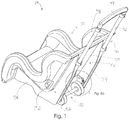
- the rolling car seat 10 includes a car seat 20, a wheel assembly 50, a footrest 38, and a handle assembly 40.
- the car seat 20 includes a back portion 22 and a seat portion 36 extending forwardly from the back portion 22 in the manner of a chair. More particularly, the back portion 22 may include opposed upper 24 and lower 26 ends, the seat portion 36 extending forwardly from the back portion lower end 26.
- the car seat 20 may include a padded material situated on respective front surfaces of the back portion 22 and seat portion 36.
- the back portion 22 includes a rear surface 28.
- the back portion 22 defines a recessed area 30 adjacent the lower end 26 thereof in which the wheel assembly 50 is housed at a withdrawn configuration as will be described in more detail below.
- the back portion 22 may also define seatbelt slots 32 configured to receive a vehicle seatbelt therethrough in order to mount the car seat 20 to a vehicle seat.
- the seat portion 36 may include a plurality of protection members (not numbered) that are configured to protect the front end of the seat portion 36 and prevent it from rolling.
- the back portion 22 defines opposed vertical handle channels 34 into which the handle assembly 40 may be received.
- the opposed handle channels 34 extend substantially between back portion upper 24 and lower 26 ends, each handle channel 34 being configured to receive handle members of the handle assembly 40.
- the handle assembly 40 may be viewed as extending directly out of a headrest.
- the handle channels 34 are shown in the drawings as openings in the back portion 22. This is only shown open for clarity and it is understood that the handle channels 34 are preferably formed inside the back portion 22 and are not open, except at upper ends thereof.
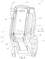
- the footrest 38 is a panel that is coupled to the seat portion 36 and movable between an inward configuration positioned inside the seat portion 36 ( Fig. 1 ) and an outward configuration extending forwardly from the seat portion 36 ( Figs. 3a and 3b ). More particularly, the footrest 38 is substantially inside the seat portion 36 at the inward configuration and is substantially outside the seat portion 36 at the outward configuration.
- the footrest also serves the function of not allowing the feet of taller children to reach the ground when the car seat is rolling and also not to allow children to push the car seat when it is at rest on the ground.
- the handle assembly 40 is operatively coupled to the back portion 22 of the car seat 20.
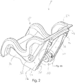
- the handle assembly 40 is movable between a retracted configuration ( Fig. 2 ) in which the handle assembly 40 does not extend upwardly above the upper end 24 of the back portion 22 and an extended configuration ( Fig. 1 ) in which the handle assembly 40 extends upwardly above the upper end 24 of the back portion 22 as will be described below.
- the handle assembly 40 includes a plurality of handle members arranged in a telescopic configuration, the handle members 42 having appropriate diameters to be slidably arranged for movement in a moderate friction fit manner.
- the handle members may be referred to later as having an outermost member 44, an innermost member 48, or an inner member although the handle assembly 40 may not necessarily be constrained to any particular number of telescopic segments.
- a handle bar 49 may extend between upper end of the innermost handle members 42 by which a user may urge the handle assembly 40 between extended and retracted configurations.
- the wheel assembly 50 includes a pair of spaced apart wheels 52 operatively coupled to the car seat back portion 22 and interconnected by an axle 54.
- the wheel assembly 50 is selectively movable between a withdrawn configuration adjacent the back portion 22 and a deployed configuration extending rearwardly from the back portion 22.
- the wheels 52 are situated in the recessed area 30 and not extending from the back portion at the withdrawn configuration and extending at least partially outside the recessed area 30 at the deployed configuration. It is understood that in some embodiments, the wheels may extend as wide as the car seat width or include wheels having an increased width so as to maximize stability.
- at least one wheel may include a wheel lock (not shown) that, when actuated, prevents the wheel from rotating.
- the wheel assembly may include wheels that are fixed in the deployed configuration and are not movable between deployed and withdrawn configurations.
- the handle assembly 40 and wheel assembly 50 include structures that cause each other to move cooperatively between their respective configurations. For instance, the wheel assembly is at the withdrawn configuration when the handle assembly 40 is at the retracted configuration ( Fig. 2 ). Even more particularly, the wheel assembly 50 is moved automatically to the withdrawn configuration when the handle assembly 40 is moved to the retracted configuration.
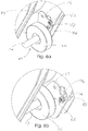
- the wheel assembly 50 includes respective mounting members 56 (one associated with each wheel 52) pivotally coupled to the car seat back portion 22 at pivot point 57 and operatively coupled to a respective wheel 52. In this way, each wheel assembly 50 is operatively coupled to the car seat 20.
- a pivotal movement of each mounting member 56 at pivot point 57 causes the wheel assembly 50 to move between withdrawn and deployed configurations. For instance, the wheel assembly 50 is at the withdrawn configuration when the mounting members 56 are pivoted as shown in Fig. 2 and, on an enlarged scale, Fig. 6b . By comparison, the wheel assembly 50 is at the deployed configuration when the mounting members 56 are pivoted as shown in Fig. 1 and, on an enlarged scale, Fig. 6a .
- the back portion 22 of the car seat 20 defines an interlink channel 58 adjacent each mounting member 56 ( Figs. 6a and 6b ).
- Each interlink channel 58 includes opposed upper 58a and lower 58b ends.
- a respective interlink channel 58 communicates a respective recessed area 30 with a respective handle channel 34.
- Each mounting member 56 includes a retraction pin 60 extending outwardly from an outside surface thereof and is configured to extend through a respective interlink channel 58 and into a respective handle channel ( Fig. 7a ).
- a retraction pin 60 is urged upwardly toward an upper end 58a of a respective interlink channel 58 when the mounting member 56 is pivoted to urge the wheel assembly toward the deployed configuration.
- the retraction pin 60 is urged downwardly toward a lower end 58b of a respective interlink channel 58 when the mounting member 56 is pivoted to urge the wheel assembly toward the withdrawn configuration.
- the outermost/lowermost handle member 44 of the plurality of handle members 42 is fixed in its position within the respective handle channel 34 ( Fig. 7a ).
- a respective retraction pin 60 extends through a respective interlink channel 58 and into a respective handle channel 34 to a position adjacent a bottom end 46 of the outermost/lowermost handle member 44 when the wheel assembly 50 is at the deployed configuration, the retraction pin 60 being at the upper end 58b of the respective interlink channel 58.
- a retraction pin 60 is downwardly displaced from the bottom end 46 of the lowermost handle member 44 when the wheel assembly 50 is at the withdrawn configuration, the retraction pin 60 being at the lower end 58b of the respective interlink channel 58 ( Figs. 5 and 7b ).
- a user may manually pull outwardly on the axle 54 to deploy the wheels, such as by inserting his foot under the axle 54 and urging it outwardly. It may be returned to the withdrawn configuration by manually pushing it back inward.
- Another means of moving the wheel assembly 50 to the withdrawn configuration is to urge the handle assembly to the retracted configuration.
- a respective innermost/lowermost handle member 44 is moved downwardly below the bottom end 46 of the outermost (fixed) handle member 44 to bear against a respective retraction pin 60 and urge it downwardly in a respective interlink channel 58 ( Fig. 7b ).
- the mounting member 56 may also include a locking spring pin 62, also commonly known as a spring plunger, adjacent the retraction pin 60.
- the outermost handle member 44 defines an aperture (not shown) adjacent the bottom end 46 thereof.
- the locking spring pin 62 extends through the mounting member 56 and is biased to extend outwardly. Accordingly, when the mounting member 56 is pivoted to the position shown in Figs. 1 , 6a , and 7a , the locking spring pin 62 is configured to be received automatically into the aperture so as to prevent any further movement of the mounting member 56 until the locking spring pin 62 is released as will be discussed below.
- the effect of actuation of the locking spring pin 62 is to prevent any unintended movement of the wheel assembly 50 from the deployed configuration to the withdrawn configuration while it is being transported/rolled.
- the wheels will not surprisingly "retract" when in use.
- the retraction pin 60 is urged downwardly in the interlink channel 58 when the innermost handle member 48 is retracted which pivots the mounting member 56 to the position that urges the wheel assembly 50 to the withdrawn configuration. More particularly, the innermost handle member 48 slides through and below the bottom end 46 of the outermost handle member 44 as shown Fig. 7b . When this occurs, the innermost handle member 48 first contacts the locking spring pin 62 and dislodges it from the aperture-- thus, disengaging the locking of the wheel assembly 50.
- the rolling car seat 10 may be strapped in to a vehicle seat by inserting a seat belt through the seat belt receiving slots 32 in a conventional manner. If, however, it is desired to remove the rolling car seat 10 from the vehicle and transport it to another location, whether to another vehicle or to a location for an entertainment event, the rolling car seat 10 may be removed from the vehicle and rolled to the desired location. Specifically, the wheel assembly 50 may be moved from a withdrawn configuration substantially in the recessed area 30 of the back portion 22 of the car seat 20 to a deployed configuration by urging it outwardly with a user's foot. This action results in the locking spring pin 62 being inserted into a lowermost handle member aperture, locking the wheel assembly 50 in the deployed configuration until specifically released by retraction of the innermost handle member 48, as described above.
- the handle assembly 40 may be automatically deployed if the user has not already grasped the handle bar 49 to do so.
- the car seat 20 may then be tipped slightly backward onto the wheels 52 and rolled or pushed by the handle bar 49 to the desired location.
- the car seat 20 may be tipped forwardly onto its bottom.
- the handle assembly 40 may be urged downwardly by the user into the handle channels 34 which automatically causes the wheel assembly to be released and urged to the withdrawn configuration.
Landscapes
- Engineering & Computer Science (AREA)
- Transportation (AREA)
- Mechanical Engineering (AREA)
- Chemical & Material Sciences (AREA)
- Combustion & Propulsion (AREA)
- Health & Medical Sciences (AREA)
- Child & Adolescent Psychology (AREA)
- General Health & Medical Sciences (AREA)
- Aviation & Aerospace Engineering (AREA)
- Carriages For Children, Sleds, And Other Hand-Operated Vehicles (AREA)
- Seats For Vehicles (AREA)
Claims (12)
- Siège-bébé roulant (10), comprenant :un siège-bébé (20) comportant une partie de dossier (22) présentant des extrémités supérieure (24) et inférieure (26) et une surface arrière (28) et une partie de siège (36) s'étendant vers l'avant depuis ladite extrémité inférieure de partie de dossier, lesdites partie de dossier et partie de siège étant configurées pour recevoir un bébé en position assise ;un ensemble de poignée (40) couplé fonctionnellement à ladite partie de dossier (22) et déplaçable sélectivement entre une configuration rétractée ne s'étendant pas au dessus de ladite extrémité supérieure de partie de dossier (24) et une configuration étendue s'étendant au-dessus de ladite extrémité supérieure de partie de dossier ;un ensemble de roues (50) comportant une paire de roues espacées (52) déplaçable sélectivement entre une configuration rentrée adjacente à ladite surface arrière de partie de dossier (28) et une configuration sortie écartée de ladite surface arrière de partie de dossier ;
dans lequel :ladite partie de dossier (28) définit une zone en retrait (30), ledit ensemble de roues (50) logeant sensiblement à l'intérieur de ladite zone en retrait dans ladite configuration rentrée et sortant sensiblement de ladite zone en retrait dans ladite configuration sortie ;ladite partie de dossier (28) définit des gorges à poignée opposées (34) s'étendant sensiblement entre ladite extrémité supérieure de partie de dossier (24) et ladite extrémité inférieure de partie de dossier (26), chaque gorge à poignée étant configurée pour recevoir de manière coulissante ledit ensemble de poignée (40) ;ledit ensemble de poignée (40) comporte : une pluralité d'éléments de poignée (42) ayant une configuration télescopique de manière à se déplacer entre lesdites configurations rétractée et étendue ; etune barre de poignée (49) s'étendant entre des extrémités supérieures d'éléments de poignée (42) respectifs au moyen de laquelle ladite pluralité d'éléments de poignée sont sélectivement poussés par un utilisateur entre lesdites configurations rétractée et étendue ;ledit ensemble de roues (50) étant couplé fonctionnellement à ladite partie de dossier (28) et comporte un élément de montage (56) couplé avec faculté de pivotement à ladite partie de dossier (22) dudit siège-bébé (10) et couplé fonctionnellement à une roue respective (52) de ladite paire de roues de manière à connecter fonctionnellement ladite paire de roues audit siège-bébé (20) ; etun mouvement de pivotement dudit élément de montage (56) amène sélectivement ladite paire de roues à se déplacer entre lesdites configurations rentrée et sortie ;caractérisé en ce que ladite partie de dossier (22) dudit siège-bébé (20) définit une gorge de raccordement (58) qui fait communiquer ladite zone en retrait (30) avec une gorge à poignée (34) respective, ladite gorge de raccordement comportant des extrémités supérieure (58a) et inférieure (58b) ;ledit élément de montage (56) comporte une tige de rétraction (60) partant d'une surface externe de celui-ci, ladite tige de rétraction étant configurée pour passer à travers ladite gorge de raccordement (58) jusque dans ladite gorge à poignée (34) ;ladite tige de rétraction (60) étant poussée vers ladite extrémité supérieure de gorge de raccordement (58a) quand ledit élément de montage est pivoté pour déplacer ladite paire de roues (52) dans ladite configuration sortie ; etladite tige de rétraction (60) étant poussée vers ladite extrémité inférieure de gorge de raccordement (58b) quand ledit élément de montage (56) est pivoté pour déplacer ladite paire de roues (52) dans ladite configuration rentrée. - Siège-bébé (10) selon la revendication 1, comprenant en outre un repose-pieds (38) couplé fonctionnellement à ladite partie de siège (36) et déplaçable de manière coulissante entre une configuration interne située à l'intérieur de ladite partie de siège et une configuration externe s'étendant vers l'avant depuis ladite partie de siège.
- Siège-bébé (10) selon la revendication 2, dans lequel ledit repose-pieds (38) est situé sensiblement à l'intérieur de ladite partie de siège (36) dans ladite configuration interne et est situé sensiblement à l'extérieur de ladite partie de siège dans ladite configuration externe.
- Siège-bébé (10) selon la revendication 1, dans lequel ledit ensemble de roues (50) est dans ladite configuration rentrée quand ledit ensemble de poignée (40) est dans ladite configuration rétractée.
- Siège-bébé (10) selon la revendication 1, dans lequel ledit ensemble de roues (50) reprend automatiquement ladite configuration rentrée quand ledit ensemble de poignée (40) est déplacé sur ladite configuration rétractée.
- Siège-bébé (10) selon la revendication 1, dans lequel :un élément de poignée inférieur (44) dudit ensemble de poignée (40) est fixé en position dans ladite gorge à poignée (34) ;ladite tige de rétraction (60) est adjacente à une extrémité inférieure dudit élément de poignée inférieur (44) quand ledit élément de montage (56) est pivoté pour déplacer ladite paire de roues (52) dans ladite configuration sortie ; etladite tige de rétraction (60) est déplacée depuis ladite extrémité inférieure dudit élément de poignée inférieur (44) quand ledit élément de montage (56) est pivoté pour déplacer ladite paire de roues (52) dans ladite configuration rentrée.
- Siège-bébé (10) selon la revendication 6, dans lequel un élément de poignée interne (48) situé dans ledit élément de poignée inférieur (44) pousse sélectivement ladite tige de rétraction (60) vers ladite extrémité inférieure de gorge de raccordement (58b) quand ledit ensemble de poignée (40) est déplacé dans ladite configuration rétractée de manière à déplacer ledit ensemble de roues (50) dans ladite configuration rentrée.
- Siège-bébé (10) selon la revendication 6, dans lequel :ledit élément de poignée inférieur (44) dudit ensemble de poignée (40) définit une ouverture adjacente à ladite extrémité inférieure (46) de celui-ci ;ledit ensemble de roues (50) comporte une tige ressort de blocage (62) qui traverse ledit élément de montage (56) et ladite gorge de raccordement (58) pour arriver jusque dans ladite gorge à poignée (34) ; etladite tige ressort de blocage (62) est configurée pour s'aligner avec ladite ouverture dans ledit élément de poignée inférieur (44) quand ladite tige de rétraction (60) est adjacente à ladite extrémité inférieure dudit élément de poignée inférieur (44) de manière à bloquer ledit ensemble de roues (50) dans ladite configuration sortie.
- Siège-bébé (10) selon la revendication 8, dans lequel ladite tige ressort de blocage (62) est débloquée de ladite ouverture quand un élément de poignée interne (48) est déplacé vers le bas en dessous de ladite extrémité inférieure lorsque ledit ensemble de poignée (40) est déplacé dans ladite configuration rétractée.
- Siège-bébé (10) selon la revendication 1, dans lequel les éléments de ladite pluralité d'éléments de poignée (44, 48) peuvent coulisser les uns par rapport aux autres dans un agencement général d'ajustement par frottement.
- Siège-bébé (10) selon la revendication 1, dans lequel ladite paire de roues (52) est couplée axialement à des éléments de montage respectifs (56) de telle sorte que ladite paire de roues puisse tourner librement.
- Siège-bébé (10) selon la revendication 1, comprenant en outre un tissu matelassé situé sur les surfaces avant de ladite partie de dossier (22) et de ladite partie de siège (36), respectivement.
Applications Claiming Priority (2)
| Application Number | Priority Date | Filing Date | Title |
|---|---|---|---|
| US13/274,396 US8544941B2 (en) | 2011-02-10 | 2011-10-17 | Rolling car seat |
| PCT/US2011/065053 WO2013058800A1 (fr) | 2011-10-17 | 2011-12-15 | Siège-bébé roulant |
Publications (3)
| Publication Number | Publication Date |
|---|---|
| EP2768698A1 EP2768698A1 (fr) | 2014-08-27 |
| EP2768698A4 EP2768698A4 (fr) | 2015-06-24 |
| EP2768698B1 true EP2768698B1 (fr) | 2017-05-31 |
Family
ID=46636328
Family Applications (1)
| Application Number | Title | Priority Date | Filing Date |
|---|---|---|---|
| EP11874241.0A Not-in-force EP2768698B1 (fr) | 2011-10-17 | 2011-12-15 | Siège-bébé roulant |
Country Status (6)
| Country | Link |
|---|---|
| US (2) | US8544941B2 (fr) |
| EP (1) | EP2768698B1 (fr) |
| CN (1) | CN103930305B (fr) |
| AU (1) | AU2011379374B2 (fr) |
| CA (1) | CA2852638C (fr) |
| WO (1) | WO2013058800A1 (fr) |
Families Citing this family (22)
| Publication number | Priority date | Publication date | Assignee | Title |
|---|---|---|---|---|
| BRPI1103245B1 (pt) * | 2010-07-15 | 2020-04-28 | Wonderland Nursery Goods | montagem de assento de segurança para crianças |
| US8544941B2 (en) * | 2011-02-10 | 2013-10-01 | Kathy Coote | Rolling car seat |
| TWM466812U (zh) * | 2013-03-08 | 2013-12-01 | Wun-Chuan Wang | 機車安全座椅 |
| CN104057993B (zh) * | 2013-03-20 | 2016-07-06 | 双馀实业有限公司 | 易控刹车的儿童两用安全载具 |
| US20150091267A1 (en) * | 2013-10-01 | 2015-04-02 | Rhett Conner | Baby car seat insta-stroller |
| US9789791B2 (en) | 2013-10-23 | 2017-10-17 | Wonderland Nurserygoods Company Limited | Child safety seat |
| US9162697B2 (en) * | 2014-01-14 | 2015-10-20 | Edvin R. Perez | Dolly for connection to child car seat to form a stroller |
| EP3164323A4 (fr) * | 2014-07-04 | 2018-03-21 | PåHoj AB | Poussette de vélo |
| US9227536B1 (en) * | 2015-06-11 | 2016-01-05 | Jim Cary | Convertible car seat and stroller |
| US9834118B2 (en) | 2015-09-18 | 2017-12-05 | Troy Kunkel | Car seat mobility system |
| CN108430276B (zh) * | 2015-11-16 | 2022-03-04 | 婴儿方舟有限公司 | 婴儿座椅 |
| PL236389B1 (pl) * | 2016-08-10 | 2021-01-11 | Dobras Berger Klaudia | Zestaw transportowy fotelika samochodowego |
| US10272804B2 (en) * | 2016-11-08 | 2019-04-30 | Wonderland Switzerland Ag | Child safety seat |
| CN106265032B (zh) * | 2016-11-11 | 2018-10-30 | 新昌县鸿吉电子科技有限公司 | 肛肠科用坐熏椅 |
| US11267376B2 (en) | 2017-05-17 | 2022-03-08 | Illa Designs, LLC | Car seat carrier |
| US10427558B1 (en) * | 2018-05-10 | 2019-10-01 | Clifford Gregory Dickens | Safety seat for use in vehicles and convertible as a pushchair |
| CN108909891A (zh) * | 2018-07-18 | 2018-11-30 | 福州职业技术学院 | 一种智能化背式安全座椅的使用方法 |
| US11447047B2 (en) * | 2019-01-10 | 2022-09-20 | Wonderland Switzerland Ag | Child safety seat |
| US11440446B2 (en) | 2019-01-10 | 2022-09-13 | Wonderland Switzerland Ag | Child restraint system |
| US10933778B1 (en) * | 2019-08-27 | 2021-03-02 | Pattie Hinson | Rolling car seat assembly |
| CN218577825U (zh) * | 2021-06-07 | 2023-03-07 | 葛莱儿婴儿产品股份有限公司 | 用于婴儿座椅及婴儿车的系统 |
| US12527417B1 (en) * | 2023-10-17 | 2026-01-20 | Shaqun Campbell | Infant car seat |
Family Cites Families (69)
| Publication number | Priority date | Publication date | Assignee | Title |
|---|---|---|---|---|
| DE1930891A1 (de) * | 1969-06-18 | 1970-12-23 | Happich Gmbh Gebr | Verwandelbarer Kindersicherheits-Autositz |
| US3632165A (en) * | 1970-08-03 | 1972-01-04 | Wilbur D Miller | Auxiliary car seat |
| US4067608A (en) * | 1975-11-26 | 1978-01-10 | Wimmersperg Heinrich F Von | Child safety restraint |
| US4381870A (en) * | 1979-05-04 | 1983-05-03 | Smarte Carte, Inc. | Versatile cart apparatus |
| US4300783A (en) * | 1980-01-22 | 1981-11-17 | The Quaker Oats Company | Convertible load carrying-ride-on vehicle |
| US4575109A (en) * | 1983-02-28 | 1986-03-11 | Cowdery Timothy K | Luggage case with retractable wheels |
| US4570956A (en) * | 1984-09-17 | 1986-02-18 | Gloria Dyer | Apparatus for converting a car seat to a stroller |
| US4685688A (en) * | 1985-02-14 | 1987-08-11 | Edwards Gregory S | Combined child safety car seat and stroller |
| US4736959A (en) * | 1986-02-05 | 1988-04-12 | Amatech Corporation | Convertible carriage |
| US4762331A (en) * | 1986-10-31 | 1988-08-09 | Gee-I-Go, Inc. | Combination automobile seat and stroller |
| US4872693A (en) * | 1987-01-23 | 1989-10-10 | Gordon Kennel | Combination infant seat and stroller |
| US4845804A (en) * | 1987-06-04 | 1989-07-11 | Underkart Industries Of Canada Ltd. | Retractable caster |
| US4989888A (en) * | 1987-08-17 | 1991-02-05 | Qureshi Khurshid A | Combination child restraint and stroller |
| US4874182A (en) * | 1987-12-28 | 1989-10-17 | Wade Parker | Stroller apparatus for juvenile car seat |
| US4822064A (en) * | 1988-01-25 | 1989-04-18 | Hunter Everett E | Combination child vehicle seat and stroller |
| US4872692A (en) * | 1988-06-03 | 1989-10-10 | Prodigy Corp. | Convertible carriage with biased wheel retraction |
| US4878680A (en) * | 1988-06-08 | 1989-11-07 | Molnar Terrence O | Stroller car seat |
| US4896894A (en) * | 1989-01-09 | 1990-01-30 | Singletary David L | Stroller carseat apparatus |
| US4902026A (en) * | 1989-02-16 | 1990-02-20 | Maldonado Robert L | Convertible car seat apparatus |
| US5022669A (en) * | 1990-06-26 | 1991-06-11 | Preston Johnson | Child travel seat |
| US5104134A (en) * | 1990-07-12 | 1992-04-14 | Rainbow Roller Venture | Child's combination carseat and stroller |
| US5149113A (en) * | 1991-04-05 | 1992-09-22 | Alldredge Rodney H | Convertible stroller and car seat |
| US5318311A (en) * | 1991-04-22 | 1994-06-07 | Bofill Julio A | Combination child vehicle seat and stroller |
| US5595393A (en) * | 1994-08-15 | 1997-01-21 | Batten; James B. | Infant car seat stroller conversion and method therefor |
| US5527089A (en) * | 1995-02-24 | 1996-06-18 | Charest; Emilien | Convertible chair and load carrier device |
| US5829826A (en) * | 1997-07-10 | 1998-11-03 | Ziccardi; Maryanne | Convertible childs chair |
| US5899467A (en) * | 1997-09-11 | 1999-05-04 | Henkel; Robert R. | Carry-on stroller case |
| US6296259B1 (en) * | 1998-01-27 | 2001-10-02 | Dreams & Visions Of Inspirations, Inc. | Child safety seat stroller |
| CN2364727Y (zh) * | 1999-02-09 | 2000-02-23 | 李芳卿 | 隐藏式行李箱滚轮 |
| US6367821B2 (en) * | 1999-02-11 | 2002-04-09 | Donald J. Thiele | Car seat and stroller assembly |
| US6237995B1 (en) * | 1999-06-03 | 2001-05-29 | Stroll-N-Go Child Products, Inc. | Carseat and stroller with folding linkage system |
| TW422013U (en) * | 2000-02-22 | 2001-02-11 | Fortune Torch Co Ltd | Control device of dual-groove type telescopic wheel for pull-bar box cart |
| GB2360938A (en) * | 2000-04-04 | 2001-10-10 | Glyn Edin Michael Tuvnes | Multi-functional infant/child seat |
| US20020060444A1 (en) * | 2000-04-14 | 2002-05-23 | Denis Cote | Convertible car seat for infants |
| US20010043000A1 (en) * | 2000-05-17 | 2001-11-22 | Hinds Jason Mark | Seating apparatus |
| US6241313B1 (en) * | 2000-05-18 | 2001-06-05 | Randall G. Lenz | Child seat attachable to a suitcase |
| US6854744B2 (en) * | 2000-09-29 | 2005-02-15 | Janet E. Brandler | Lightweight convertible car seat and stroller |
| GB2377677B (en) * | 2001-07-19 | 2004-09-29 | Andrew Bargery | Transporter |
| US6976685B1 (en) * | 2002-02-15 | 2005-12-20 | Samsonite Corporation | Wheeled car seat |
| US6729630B2 (en) * | 2002-05-10 | 2004-05-04 | Leszek G. Szmidt | Child car seat/stroller |
| US20030227149A1 (en) * | 2002-06-05 | 2003-12-11 | Budge Paul W | Dolly with child car seat |
| US6612645B1 (en) * | 2002-06-06 | 2003-09-02 | Sunny Wheel Industrial Co., Ltd. | Baby seat structure for bicycles |
| US20040021353A1 (en) * | 2002-07-31 | 2004-02-05 | Lozano Michael M. | Children's foldable luggage seat |
| US7090291B2 (en) * | 2002-09-10 | 2006-08-15 | Birchfield Daphne D | Combination child vehicle seat and temporary stroller |
| US20040173997A1 (en) * | 2003-03-03 | 2004-09-09 | Rachelle Voll | Combination car seat, carrier, and stroller for infants |
| GB0311256D0 (en) * | 2003-05-16 | 2003-06-18 | Bishop Gordon W | Case with seat |
| US6938915B2 (en) * | 2003-05-30 | 2005-09-06 | Go-Go Babyz Corp. | Vehicle restraint system for a child |
| US7354049B2 (en) * | 2003-11-19 | 2008-04-08 | Tim Schmidt | Infant carrying system |
| US6986518B1 (en) * | 2003-12-01 | 2006-01-17 | Gary Lee Besaw | Combined baby car seat and stroller |
| US6971655B1 (en) * | 2004-03-17 | 2005-12-06 | Harris Jennie V | Stroller and safety seat combination |
| US7100976B1 (en) * | 2004-05-17 | 2006-09-05 | Gary Desalve | Apparatus for an integrated child restraint seat and transport for carry on luggage |
| US7011316B1 (en) * | 2004-07-06 | 2006-03-14 | Marlyn Peridon | Infant car seat stroller |
| US7293792B2 (en) * | 2005-03-31 | 2007-11-13 | Wilson Zachary C | Transportable child booster seat/carrying bag |
| US7311353B1 (en) * | 2005-04-15 | 2007-12-25 | Johnson Dwight L | Infant seat assembly |
| US7600766B2 (en) * | 2006-05-31 | 2009-10-13 | Sandra Erskine | Rolling infant car seat |
| US7517011B2 (en) * | 2006-06-28 | 2009-04-14 | Adil Aliyevich Aliev | Combination child carrier |
| US7543886B2 (en) * | 2006-09-29 | 2009-06-09 | Suzanne Gutierrez-Hedges | Child car seat with alternate mobility attributes |
| US20100019547A1 (en) * | 2007-10-17 | 2010-01-28 | Melissa Gray | Car Seat with Rolling Wheels and Method to use |
| US20090159385A1 (en) * | 2007-12-19 | 2009-06-25 | Cosmoda Corporation | Travel bag with stowable seat |
| US7540507B1 (en) * | 2008-04-10 | 2009-06-02 | Kennedy James M | Child seat and stroller assembly |
| US8851503B2 (en) * | 2008-09-29 | 2014-10-07 | Robert L. Tyson, III | Dual-chair beach wagon |
| US8128103B1 (en) * | 2009-01-13 | 2012-03-06 | Marie Schutzendorf | Deployable side seat for a baby stroller |
| US8182030B1 (en) * | 2010-04-14 | 2012-05-22 | Britten Craig M | Child carrier luggage assembly |
| US8544941B2 (en) * | 2011-02-10 | 2013-10-01 | Kathy Coote | Rolling car seat |
| US20150091267A1 (en) * | 2013-10-01 | 2015-04-02 | Rhett Conner | Baby car seat insta-stroller |
| US9308839B1 (en) * | 2014-03-04 | 2016-04-12 | Michael Gleckler | Child car seat transportion system |
| US9963158B2 (en) * | 2016-01-26 | 2018-05-08 | Munchkin, Inc. | Carrier transporter |
| US20180009341A1 (en) * | 2016-07-05 | 2018-01-11 | Jennifer Carlile | Car seat stroller system and method |
| US10427558B1 (en) * | 2018-05-10 | 2019-10-01 | Clifford Gregory Dickens | Safety seat for use in vehicles and convertible as a pushchair |
-
2011
- 2011-10-17 US US13/274,396 patent/US8544941B2/en not_active Ceased
- 2011-12-15 EP EP11874241.0A patent/EP2768698B1/fr not_active Not-in-force
- 2011-12-15 CA CA2852638A patent/CA2852638C/fr active Active
- 2011-12-15 WO PCT/US2011/065053 patent/WO2013058800A1/fr not_active Ceased
- 2011-12-15 CN CN201180074256.1A patent/CN103930305B/zh active Active
- 2011-12-15 AU AU2011379374A patent/AU2011379374B2/en not_active Ceased
-
2022
- 2022-04-18 US US17/722,625 patent/USRE49798E1/en active Active
Also Published As
| Publication number | Publication date |
|---|---|
| EP2768698A1 (fr) | 2014-08-27 |
| CA2852638A1 (fr) | 2013-04-25 |
| WO2013058800A1 (fr) | 2013-04-25 |
| CN103930305A (zh) | 2014-07-16 |
| US20120205947A1 (en) | 2012-08-16 |
| AU2011379374B2 (en) | 2017-05-11 |
| CA2852638C (fr) | 2018-09-11 |
| US8544941B2 (en) | 2013-10-01 |
| USRE49798E1 (en) | 2024-01-16 |
| EP2768698A4 (fr) | 2015-06-24 |
| CN103930305B (zh) | 2018-04-24 |
| AU2011379374A1 (en) | 2014-05-29 |
Similar Documents
| Publication | Publication Date | Title |
|---|---|---|
| USRE49798E1 (en) | Rolling car seat | |
| US9561816B2 (en) | Compact foldable stroller with one-handed fold control | |
| US8955855B2 (en) | Infant wagon | |
| EP2398687B1 (fr) | Poussette pliante | |
| US6676140B1 (en) | Expandable stroller | |
| US9242585B2 (en) | Infant car seat assembly | |
| US8998242B2 (en) | Dual-purpose safety baby carrier | |
| US11267376B2 (en) | Car seat carrier | |
| US11350713B2 (en) | Combination luggage and child carrier | |
| US20180009341A1 (en) | Car seat stroller system and method | |
| US20230159079A1 (en) | Child transportation system | |
| CN107813858A (zh) | 手推车 | |
| JP2012505101A (ja) | 装置及び方法 | |
| GB2499422A (en) | Car seat having retractable wheeled legs | |
| JP2020203678A (ja) | 折り畳み式三輪車 | |
| EP4157693B1 (fr) | Système de poussette pour enfant convertible avec panier auxiliaire | |
| US20170210407A1 (en) | Foldable stroller | |
| WO2010052257A1 (fr) | Poussette pliante | |
| CN221635192U (zh) | 可转换手提箱婴儿车装置 | |
| HK40013592A (en) | Combination luggage and child carrier | |
| GB2495303A (en) | Child safety seat which can be used as a carrier or pushchair |
Legal Events
| Date | Code | Title | Description |
|---|---|---|---|
| PUAI | Public reference made under article 153(3) epc to a published international application that has entered the european phase |
Free format text: ORIGINAL CODE: 0009012 |
|
| 17P | Request for examination filed |
Effective date: 20140512 |
|
| AK | Designated contracting states |
Kind code of ref document: A1 Designated state(s): AL AT BE BG CH CY CZ DE DK EE ES FI FR GB GR HR HU IE IS IT LI LT LU LV MC MK MT NL NO PL PT RO RS SE SI SK SM TR |
|
| DAX | Request for extension of the european patent (deleted) | ||
| RA4 | Supplementary search report drawn up and despatched (corrected) |
Effective date: 20150521 |
|
| RIC1 | Information provided on ipc code assigned before grant |
Ipc: B62B 7/00 20060101AFI20150515BHEP Ipc: B62B 7/12 20060101ALI20150515BHEP Ipc: B62B 7/02 20060101ALI20150515BHEP Ipc: B62B 9/20 20060101ALN20150515BHEP Ipc: B60N 2/32 20060101ALI20150515BHEP |
|
| REG | Reference to a national code |
Ref country code: DE Ref legal event code: R079 Ref document number: 602011038450 Country of ref document: DE Free format text: PREVIOUS MAIN CLASS: B60N0002320000 Ipc: B62B0007000000 |
|
| GRAP | Despatch of communication of intention to grant a patent |
Free format text: ORIGINAL CODE: EPIDOSNIGR1 |
|
| RIC1 | Information provided on ipc code assigned before grant |
Ipc: B62B 7/00 20060101AFI20161214BHEP Ipc: B62B 7/12 20060101ALI20161214BHEP Ipc: B62B 9/20 20060101ALN20161214BHEP Ipc: B62B 7/02 20060101ALI20161214BHEP Ipc: B60N 2/32 20060101ALI20161214BHEP |
|
| INTG | Intention to grant announced |
Effective date: 20170112 |
|
| GRAS | Grant fee paid |
Free format text: ORIGINAL CODE: EPIDOSNIGR3 |
|
| GRAA | (expected) grant |
Free format text: ORIGINAL CODE: 0009210 |
|
| AK | Designated contracting states |
Kind code of ref document: B1 Designated state(s): AL AT BE BG CH CY CZ DE DK EE ES FI FR GB GR HR HU IE IS IT LI LT LU LV MC MK MT NL NO PL PT RO RS SE SI SK SM TR |
|
| REG | Reference to a national code |
Ref country code: CH Ref legal event code: EP Ref country code: GB Ref legal event code: FG4D |
|
| REG | Reference to a national code |
Ref country code: AT Ref legal event code: REF Ref document number: 897166 Country of ref document: AT Kind code of ref document: T Effective date: 20170615 |
|
| REG | Reference to a national code |
Ref country code: IE Ref legal event code: FG4D |
|
| REG | Reference to a national code |
Ref country code: DE Ref legal event code: R096 Ref document number: 602011038450 Country of ref document: DE |
|
| REG | Reference to a national code |
Ref country code: NL Ref legal event code: MP Effective date: 20170531 |
|
| REG | Reference to a national code |
Ref country code: LT Ref legal event code: MG4D |
|
| REG | Reference to a national code |
Ref country code: AT Ref legal event code: MK05 Ref document number: 897166 Country of ref document: AT Kind code of ref document: T Effective date: 20170531 |
|
| PG25 | Lapsed in a contracting state [announced via postgrant information from national office to epo] |
Ref country code: AT Free format text: LAPSE BECAUSE OF FAILURE TO SUBMIT A TRANSLATION OF THE DESCRIPTION OR TO PAY THE FEE WITHIN THE PRESCRIBED TIME-LIMIT Effective date: 20170531 Ref country code: ES Free format text: LAPSE BECAUSE OF FAILURE TO SUBMIT A TRANSLATION OF THE DESCRIPTION OR TO PAY THE FEE WITHIN THE PRESCRIBED TIME-LIMIT Effective date: 20170531 Ref country code: GR Free format text: LAPSE BECAUSE OF FAILURE TO SUBMIT A TRANSLATION OF THE DESCRIPTION OR TO PAY THE FEE WITHIN THE PRESCRIBED TIME-LIMIT Effective date: 20170901 Ref country code: LT Free format text: LAPSE BECAUSE OF FAILURE TO SUBMIT A TRANSLATION OF THE DESCRIPTION OR TO PAY THE FEE WITHIN THE PRESCRIBED TIME-LIMIT Effective date: 20170531 Ref country code: NO Free format text: LAPSE BECAUSE OF FAILURE TO SUBMIT A TRANSLATION OF THE DESCRIPTION OR TO PAY THE FEE WITHIN THE PRESCRIBED TIME-LIMIT Effective date: 20170831 Ref country code: FI Free format text: LAPSE BECAUSE OF FAILURE TO SUBMIT A TRANSLATION OF THE DESCRIPTION OR TO PAY THE FEE WITHIN THE PRESCRIBED TIME-LIMIT Effective date: 20170531 Ref country code: HR Free format text: LAPSE BECAUSE OF FAILURE TO SUBMIT A TRANSLATION OF THE DESCRIPTION OR TO PAY THE FEE WITHIN THE PRESCRIBED TIME-LIMIT Effective date: 20170531 |
|
| PG25 | Lapsed in a contracting state [announced via postgrant information from national office to epo] |
Ref country code: LV Free format text: LAPSE BECAUSE OF FAILURE TO SUBMIT A TRANSLATION OF THE DESCRIPTION OR TO PAY THE FEE WITHIN THE PRESCRIBED TIME-LIMIT Effective date: 20170531 Ref country code: NL Free format text: LAPSE BECAUSE OF FAILURE TO SUBMIT A TRANSLATION OF THE DESCRIPTION OR TO PAY THE FEE WITHIN THE PRESCRIBED TIME-LIMIT Effective date: 20170531 Ref country code: SE Free format text: LAPSE BECAUSE OF FAILURE TO SUBMIT A TRANSLATION OF THE DESCRIPTION OR TO PAY THE FEE WITHIN THE PRESCRIBED TIME-LIMIT Effective date: 20170531 Ref country code: IS Free format text: LAPSE BECAUSE OF FAILURE TO SUBMIT A TRANSLATION OF THE DESCRIPTION OR TO PAY THE FEE WITHIN THE PRESCRIBED TIME-LIMIT Effective date: 20170930 Ref country code: RS Free format text: LAPSE BECAUSE OF FAILURE TO SUBMIT A TRANSLATION OF THE DESCRIPTION OR TO PAY THE FEE WITHIN THE PRESCRIBED TIME-LIMIT Effective date: 20170531 Ref country code: BG Free format text: LAPSE BECAUSE OF FAILURE TO SUBMIT A TRANSLATION OF THE DESCRIPTION OR TO PAY THE FEE WITHIN THE PRESCRIBED TIME-LIMIT Effective date: 20170831 |
|
| REG | Reference to a national code |
Ref country code: FR Ref legal event code: PLFP Year of fee payment: 7 |
|
| PG25 | Lapsed in a contracting state [announced via postgrant information from national office to epo] |
Ref country code: DK Free format text: LAPSE BECAUSE OF FAILURE TO SUBMIT A TRANSLATION OF THE DESCRIPTION OR TO PAY THE FEE WITHIN THE PRESCRIBED TIME-LIMIT Effective date: 20170531 Ref country code: RO Free format text: LAPSE BECAUSE OF FAILURE TO SUBMIT A TRANSLATION OF THE DESCRIPTION OR TO PAY THE FEE WITHIN THE PRESCRIBED TIME-LIMIT Effective date: 20170531 Ref country code: EE Free format text: LAPSE BECAUSE OF FAILURE TO SUBMIT A TRANSLATION OF THE DESCRIPTION OR TO PAY THE FEE WITHIN THE PRESCRIBED TIME-LIMIT Effective date: 20170531 Ref country code: CZ Free format text: LAPSE BECAUSE OF FAILURE TO SUBMIT A TRANSLATION OF THE DESCRIPTION OR TO PAY THE FEE WITHIN THE PRESCRIBED TIME-LIMIT Effective date: 20170531 Ref country code: SK Free format text: LAPSE BECAUSE OF FAILURE TO SUBMIT A TRANSLATION OF THE DESCRIPTION OR TO PAY THE FEE WITHIN THE PRESCRIBED TIME-LIMIT Effective date: 20170531 |
|
| PG25 | Lapsed in a contracting state [announced via postgrant information from national office to epo] |
Ref country code: SM Free format text: LAPSE BECAUSE OF FAILURE TO SUBMIT A TRANSLATION OF THE DESCRIPTION OR TO PAY THE FEE WITHIN THE PRESCRIBED TIME-LIMIT Effective date: 20170531 Ref country code: PL Free format text: LAPSE BECAUSE OF FAILURE TO SUBMIT A TRANSLATION OF THE DESCRIPTION OR TO PAY THE FEE WITHIN THE PRESCRIBED TIME-LIMIT Effective date: 20170531 |
|
| REG | Reference to a national code |
Ref country code: DE Ref legal event code: R097 Ref document number: 602011038450 Country of ref document: DE |
|
| PLBE | No opposition filed within time limit |
Free format text: ORIGINAL CODE: 0009261 |
|
| STAA | Information on the status of an ep patent application or granted ep patent |
Free format text: STATUS: NO OPPOSITION FILED WITHIN TIME LIMIT |
|
| 26N | No opposition filed |
Effective date: 20180301 |
|
| PG25 | Lapsed in a contracting state [announced via postgrant information from national office to epo] |
Ref country code: SI Free format text: LAPSE BECAUSE OF FAILURE TO SUBMIT A TRANSLATION OF THE DESCRIPTION OR TO PAY THE FEE WITHIN THE PRESCRIBED TIME-LIMIT Effective date: 20170531 |
|
| REG | Reference to a national code |
Ref country code: DE Ref legal event code: R119 Ref document number: 602011038450 Country of ref document: DE |
|
| PGFP | Annual fee paid to national office [announced via postgrant information from national office to epo] |
Ref country code: IE Payment date: 20180411 Year of fee payment: 7 |
|
| REG | Reference to a national code |
Ref country code: CH Ref legal event code: PL |
|
| PG25 | Lapsed in a contracting state [announced via postgrant information from national office to epo] |
Ref country code: LU Free format text: LAPSE BECAUSE OF NON-PAYMENT OF DUE FEES Effective date: 20171215 Ref country code: MT Free format text: LAPSE BECAUSE OF NON-PAYMENT OF DUE FEES Effective date: 20171215 |
|
| REG | Reference to a national code |
Ref country code: BE Ref legal event code: MM Effective date: 20171231 |
|
| PG25 | Lapsed in a contracting state [announced via postgrant information from national office to epo] |
Ref country code: DE Free format text: LAPSE BECAUSE OF NON-PAYMENT OF DUE FEES Effective date: 20180703 |
|
| PG25 | Lapsed in a contracting state [announced via postgrant information from national office to epo] |
Ref country code: LI Free format text: LAPSE BECAUSE OF NON-PAYMENT OF DUE FEES Effective date: 20171231 Ref country code: CH Free format text: LAPSE BECAUSE OF NON-PAYMENT OF DUE FEES Effective date: 20171231 Ref country code: BE Free format text: LAPSE BECAUSE OF NON-PAYMENT OF DUE FEES Effective date: 20171231 |
|
| PG25 | Lapsed in a contracting state [announced via postgrant information from national office to epo] |
Ref country code: HU Free format text: LAPSE BECAUSE OF FAILURE TO SUBMIT A TRANSLATION OF THE DESCRIPTION OR TO PAY THE FEE WITHIN THE PRESCRIBED TIME-LIMIT; INVALID AB INITIO Effective date: 20111215 Ref country code: MC Free format text: LAPSE BECAUSE OF FAILURE TO SUBMIT A TRANSLATION OF THE DESCRIPTION OR TO PAY THE FEE WITHIN THE PRESCRIBED TIME-LIMIT Effective date: 20170531 |
|
| REG | Reference to a national code |
Ref country code: IE Ref legal event code: MM4A |
|
| PG25 | Lapsed in a contracting state [announced via postgrant information from national office to epo] |
Ref country code: IE Free format text: LAPSE BECAUSE OF NON-PAYMENT OF DUE FEES Effective date: 20181215 Ref country code: CY Free format text: LAPSE BECAUSE OF NON-PAYMENT OF DUE FEES Effective date: 20170531 |
|
| PG25 | Lapsed in a contracting state [announced via postgrant information from national office to epo] |
Ref country code: MK Free format text: LAPSE BECAUSE OF FAILURE TO SUBMIT A TRANSLATION OF THE DESCRIPTION OR TO PAY THE FEE WITHIN THE PRESCRIBED TIME-LIMIT Effective date: 20170531 |
|
| PG25 | Lapsed in a contracting state [announced via postgrant information from national office to epo] |
Ref country code: TR Free format text: LAPSE BECAUSE OF FAILURE TO SUBMIT A TRANSLATION OF THE DESCRIPTION OR TO PAY THE FEE WITHIN THE PRESCRIBED TIME-LIMIT Effective date: 20170531 |
|
| PG25 | Lapsed in a contracting state [announced via postgrant information from national office to epo] |
Ref country code: PT Free format text: LAPSE BECAUSE OF FAILURE TO SUBMIT A TRANSLATION OF THE DESCRIPTION OR TO PAY THE FEE WITHIN THE PRESCRIBED TIME-LIMIT Effective date: 20170531 |
|
| PG25 | Lapsed in a contracting state [announced via postgrant information from national office to epo] |
Ref country code: AL Free format text: LAPSE BECAUSE OF FAILURE TO SUBMIT A TRANSLATION OF THE DESCRIPTION OR TO PAY THE FEE WITHIN THE PRESCRIBED TIME-LIMIT Effective date: 20170531 |
|
| PGFP | Annual fee paid to national office [announced via postgrant information from national office to epo] |
Ref country code: GB Payment date: 20231228 Year of fee payment: 13 |
|
| PGFP | Annual fee paid to national office [announced via postgrant information from national office to epo] |
Ref country code: IT Payment date: 20231228 Year of fee payment: 13 Ref country code: FR Payment date: 20231221 Year of fee payment: 13 |
|
| GBPC | Gb: european patent ceased through non-payment of renewal fee |
Effective date: 20241215 |
|
| PG25 | Lapsed in a contracting state [announced via postgrant information from national office to epo] |
Ref country code: IT Free format text: LAPSE BECAUSE OF NON-PAYMENT OF DUE FEES Effective date: 20241215 |
|
| PG25 | Lapsed in a contracting state [announced via postgrant information from national office to epo] |
Ref country code: GB Free format text: LAPSE BECAUSE OF NON-PAYMENT OF DUE FEES Effective date: 20241215 |
|
| PG25 | Lapsed in a contracting state [announced via postgrant information from national office to epo] |
Ref country code: FR Free format text: LAPSE BECAUSE OF NON-PAYMENT OF DUE FEES Effective date: 20241231 |