EP2768717B1 - Elektromechanische kraftfahrzeuglenkung - Google Patents
Elektromechanische kraftfahrzeuglenkung Download PDFInfo
- Publication number
- EP2768717B1 EP2768717B1 EP12769907.2A EP12769907A EP2768717B1 EP 2768717 B1 EP2768717 B1 EP 2768717B1 EP 12769907 A EP12769907 A EP 12769907A EP 2768717 B1 EP2768717 B1 EP 2768717B1
- Authority
- EP
- European Patent Office
- Prior art keywords
- bearing
- outer ring
- housing
- sleeve
- frame
- Prior art date
- Legal status (The legal status is an assumption and is not a legal conclusion. Google has not performed a legal analysis and makes no representation as to the accuracy of the status listed.)
- Not-in-force
Links
Images

Classifications
-
- B—PERFORMING OPERATIONS; TRANSPORTING
- B62—LAND VEHICLES FOR TRAVELLING OTHERWISE THAN ON RAILS
- B62D—MOTOR VEHICLES; TRAILERS
- B62D5/00—Power-assisted or power-driven steering
- B62D5/04—Power-assisted or power-driven steering electrical, e.g. using an electric servo-motor connected to, or forming part of, the steering gear
- B62D5/0403—Power-assisted or power-driven steering electrical, e.g. using an electric servo-motor connected to, or forming part of, the steering gear characterised by constructional features, e.g. common housing for motor and gear box
-
- B—PERFORMING OPERATIONS; TRANSPORTING
- B62—LAND VEHICLES FOR TRAVELLING OTHERWISE THAN ON RAILS
- B62D—MOTOR VEHICLES; TRAILERS
- B62D5/00—Power-assisted or power-driven steering
- B62D5/04—Power-assisted or power-driven steering electrical, e.g. using an electric servo-motor connected to, or forming part of, the steering gear
- B62D5/0442—Conversion of rotational into longitudinal movement
- B62D5/0445—Screw drives
- B62D5/0448—Ball nuts
-
- F—MECHANICAL ENGINEERING; LIGHTING; HEATING; WEAPONS; BLASTING
- F16—ENGINEERING ELEMENTS AND UNITS; GENERAL MEASURES FOR PRODUCING AND MAINTAINING EFFECTIVE FUNCTIONING OF MACHINES OR INSTALLATIONS; THERMAL INSULATION IN GENERAL
- F16C—SHAFTS; FLEXIBLE SHAFTS; ELEMENTS OR CRANKSHAFT MECHANISMS; ROTARY BODIES OTHER THAN GEARING ELEMENTS; BEARINGS
- F16C27/00—Elastic or yielding bearings or bearing supports, for exclusively rotary movement
- F16C27/06—Elastic or yielding bearings or bearing supports, for exclusively rotary movement by means of parts of rubber or like materials
- F16C27/066—Ball or roller bearings
-
- F—MECHANICAL ENGINEERING; LIGHTING; HEATING; WEAPONS; BLASTING
- F16—ENGINEERING ELEMENTS AND UNITS; GENERAL MEASURES FOR PRODUCING AND MAINTAINING EFFECTIVE FUNCTIONING OF MACHINES OR INSTALLATIONS; THERMAL INSULATION IN GENERAL
- F16C—SHAFTS; FLEXIBLE SHAFTS; ELEMENTS OR CRANKSHAFT MECHANISMS; ROTARY BODIES OTHER THAN GEARING ELEMENTS; BEARINGS
- F16C2326/00—Articles relating to transporting
- F16C2326/20—Land vehicles
- F16C2326/24—Steering systems, e.g. steering rods or columns
-
- F—MECHANICAL ENGINEERING; LIGHTING; HEATING; WEAPONS; BLASTING
- F16—ENGINEERING ELEMENTS AND UNITS; GENERAL MEASURES FOR PRODUCING AND MAINTAINING EFFECTIVE FUNCTIONING OF MACHINES OR INSTALLATIONS; THERMAL INSULATION IN GENERAL
- F16C—SHAFTS; FLEXIBLE SHAFTS; ELEMENTS OR CRANKSHAFT MECHANISMS; ROTARY BODIES OTHER THAN GEARING ELEMENTS; BEARINGS
- F16C25/00—Bearings for exclusively rotary movement adjustable for wear or play
- F16C25/06—Ball or roller bearings
- F16C25/08—Ball or roller bearings self-adjusting
- F16C25/083—Ball or roller bearings self-adjusting with resilient means acting axially on a race ring to preload the bearing
-
- F—MECHANICAL ENGINEERING; LIGHTING; HEATING; WEAPONS; BLASTING
- F16—ENGINEERING ELEMENTS AND UNITS; GENERAL MEASURES FOR PRODUCING AND MAINTAINING EFFECTIVE FUNCTIONING OF MACHINES OR INSTALLATIONS; THERMAL INSULATION IN GENERAL
- F16H—GEARING
- F16H25/00—Gearings comprising primarily only cams, cam-followers and screw-and-nut mechanisms
- F16H25/18—Gearings comprising primarily only cams, cam-followers and screw-and-nut mechanisms for conveying or interconverting oscillating or reciprocating motions
- F16H25/20—Screw mechanisms
- F16H25/24—Elements essential to such mechanisms, e.g. screws, nuts
- F16H2025/2445—Supports or other means for compensating misalignment or offset between screw and nut
Definitions
- the present invention relates to a power steering, in particular for a motor vehicle, with a servo motor which drives an axially displaceable component via a rotatably mounted in a frame, but axially immovable nut according to the preamble of claim 1.
- a servo motor which drives an axially displaceable component via a rotatably mounted in a frame, but axially immovable nut according to the preamble of claim 1.
- the ball nut is either rigidly mounted in the housing or by using spring elements and special design of the housing or the bearing allows a certain longitudinal and tilting movement.
- a spherical bearing in which both the bearing ring and the frame have a spherical surface is also known. In this solution, the center of the spherical surface in the center plane of the bearing is structurally determined.
- roller bearings and spherical roller bearings which allow an angular error of the shaft.
- the goal of these bearings is the tolerance compensation, whereby tensioning of the ball screw can be avoided.
- the dynamic and static load of the components is reduced. This results in improved acoustic properties and the reduction of mechanical play, which results from thermal expansion of the components.
- the DE 103 10 492 A1 describes a power steering, in particular for motor vehicles, with a servomotor formed as an electric motor, which rotates a designed as a push rod, axially displaceable component via a rotatably mounted in a frame formed as a steering housing, but axially non-displaceably mounted nut.
- the servo motor, the push rod and the nut are mounted by means of an eccentric bearing ring such that the center distance between the engine bore of the servomotor and the push rod is variable, which allows a simple, rapid installation of the power steering.
- an electric steering apparatus which comprises a rack, which is connected to a steering shaft, a motor for assisting a steering force with a coaxially arranged on the rack rotor, a spindle drive, in which balls between a keyed to the rotor nut and one on the Rack formed screw are inserted, and having a housing which is designed approximately cylindrical overall.
- the nut of the ball screw mechanism is rotatably supported in a bearing inside the nut housing portion.
- the EP 1 571 067 A1 discloses the elastic mounting of a worm shaft coaxially surrounds the motor of a servomotor motor.
- the generic EP 2 049 383 81 shows a solution to enable or improve the pivotability of the radial bearing. It is intended to provide a convex curvature on the outer circumference of the outer ring or to provide the nut on which the inner ring sits, with a convex curvature. having. Due to the convex curvature of the outer circumference of the outer ring or the nut, an exemption of the radial bearing and a pivotability of the nut and the axially displaceable component to be achieved.
- a steel ring with a vulcanized element is provided with elastomeric properties, which should allow for changing loads axial and radial damping and the implementation and damping of the pivotal movement of the axially displaceable component.
- elastomeric properties should allow for changing loads axial and radial damping and the implementation and damping of the pivotal movement of the axially displaceable component.
- the DE10 2010 002958 A1 discloses a rolling bearing whose outer ring is divided into two ring parts, which are sprung axially against each other with corrugated springs.
- the contact surface of the outer ring with the frame is narrow due to the formation of the outer ring.
- the contact surface is narrow because it is designed as a circumferential rib of the bearing seat or linearly by means of a convex, inwardly pointing to the bearing surface of the bearing seat.
- the invention is therefore an object of the invention to provide a power steering with a tiltable mounting of the ball nut, which can be realized with simpler components and is easy to install. This object is achieved by a power steering with the features of claim 1.
- the spring elements are formed as corrugated springs, an axial springing of the bearing and thus the mother with very simple, inexpensive and proven in practice components is possible.
- the frame which usually comprises the steering housing or parts thereof, can be made of a light metal alloy.
- the thrust washers prevent the corrugated springs working during use from getting into the light metal.
- a direct support of the bearing outer ring relative to the frame results when the corrugated springs are arranged respectively on each side of the bearing between the outer ring of the bearing and a collar of the frame.
- the frame may comprise a housing and a housing cover, wherein one of the annular collars is formed on the housing cover and wherein the other annular collar is formed on the housing or on a sleeve insertable into the housing. The embodiment with the separate, insertable into the housing sleeve is easier to assemble.
- the sleeve can also have a bearing seat which holds the bearing outer ring of the bearing on its outer peripheral surface.
- the bearing can be pre-assembled with the axial support in the sleeve.
- the nut is already mounted in the bearing, so that the insertion of the sleeve represents the assembly of the entire assembly.
- the bearing seat for the bearing of the nut forms with the bearing outer ring a contact surface, which is narrower in the axial direction of the arrangement than the bearing outer ring itself.
- This contact surface is designed in the form of a circumferential ridge or a circumferential rib, which in the rest position of the arrangement approximately centrally on the Bearing outer ring rests.
- the contact surface between the bearing outer ring and the bearing seat may alternatively also be formed almost linearly, when the contact surface is formed as a portion of a convex, inwardly to the bearing having surface of the bearing seat, wherein as above the contact surface circumferentially and in the axial direction of the arrangement approximately centrally should abut the outer surface of the bearing outer ring.
- a section of an electrically driven motor vehicle power steering is shown in a longitudinal section.
- the detail shows the upper half of a longitudinal section along the axis of symmetry A in a region in which a ball nut 1 with a threaded spindle 2 is engaged.
- balls 3 of a ball screw are arranged in a conventional manner.
- the ball nut 1 is rotatably mounted in a bearing 4.
- the bearing 4 has an inner ring 5, which sits firmly on a bearing seat 6 of the ball nut 1.
- the bearing 4 further has an outer ring 7, which is arranged in a bearing seat 8 of a frame.
- the frame comprises a steering housing 9 which is approximately tubular in this area and which is closed by a housing cover 10.
- the housing cover 10 surrounds the steering housing 9 on its outer side and is fastened by means not shown fastening means to the steering housing 9.
- the ball nut 1 further carries an intermediate sleeve 11, on which a pulley 12 of a toothed belt drive is rotatably mounted.
- an intermediate sleeve 11 on which a pulley 12 of a toothed belt drive is rotatably mounted.
- the bearing outer ring 7 is, as usual in rolling bearings, provided with an outer peripheral surface 15, a first end face 16 and a second end face 17.
- a corrugated spring 18 At the first end face 16 is a corrugated spring 18, the is supported against a thrust washer 19.
- the second end face 17 is supported against a corrugated spring 20, which in turn is supported in the axial direction of the longitudinal axis A against a thrust washer 21.
- the corrugated springs 18 and 20 are annular springs which have an approximately uniform radius, which preferably coincides with the radius of the bearing outer ring 7.
- the corrugated springs 18 and 20 are not flat, but have in the side view accordingly Fig. 1 a wavy shape.
- the corrugated springs 18 and 20 are therefore simple, proven components that are not destroyed by high load in the axial direction.
- the thrust washers 19 and 21 are steel rings, which are preferably hardened. These steel rings are suitable to receive during operation slight movement of the corrugated springs 18 and 20, without the corrugated springs also made of hard material in the thrust washers 19 and 21 incorporated.
- the thrust washers 19 and 21 are therefore particularly advantageous to use when the frame (here the steering housing 9 and the housing cover 10) is made of a light metal alloy or a similar, relatively soft material.
- the construction shown provides that the thrust washer 19 rests directly on an end face 22 of the steering housing 9.
- the second thrust washer 21 is correspondingly applied to an annular collar 23 of the housing cover 10, which is opposite in the installed state of the end face 22 at a distance.
- the bearing outer ring 7 is supported with its outer peripheral surface 15 on a web 24 which is formed circumferentially in the bearing seat 8.
- the web 24 forms with the bearing outer ring 7 a narrow, annular circumferential bearing surface, which allows tilting of the bearing outer ring 7 relative to the bearing seat 8 to a lesser extent.
- the bearing inner ring 5 is in its bearing seat 6 by a threaded nut 25 secured, which is screwed onto a corresponding thread of the nut 1.
- the assembly is mounted, which is non-rotatable with the nut 1.
- This assembly includes the sleeve 11 and the pulley 12 and the bearing 4.
- This assembly is then inserted together with the corrugated spring 18 and the thrust washer 19 in the steering housing 9 until the thrust washer 19 rests on the end face 22 of the steering housing 9.
- the threaded spindle 2 can be spindled into the nut 1 before or after this assembly process.
- the corrugated spring 20 and the thrust washer 21 are placed on the bearing outer ring 7 and the housing cover 10 is placed and fastened in a flange portion, not shown, on the housing 9.
- an electric servomotor via a belt drive, the pulley 12 and thus put the nut 1 in rotation, which is offset via the balls 3, the threaded spindle 2 in an axial movement, which ultimately causes the steering movement for the motor vehicle via a belt drive.
- the ball nut 1 can move in the bearing seat 8 in the manner described in the axial direction against the restoring force of the corrugated springs 18 and 20.
- the narrow contact surface in the region of the web 24 also allows a slight tilting movement. As a result, dynamic loads can be absorbed, which would lead to a high load on the nut 1 and the threaded spindle 2 in the sphere of balls 3 without this special storage.
- FIG. 2 Another embodiment of the invention is in FIG. 2 shown.
- the same or equivalent components bear the same reference numerals.
- the bearing 4 is according to the embodiment Fig. 2 designed smaller. Its outer bearing ring 7 is supported as in the Fig. 1 in the axial direction to the right over the wave spring 20 and the thrust washer 21 against the annular collar 23 of the housing cover 10 from. In the opposite axial direction, the bearing outer ring 7 is supported with its end face 16 via the wave spring 18 and the thrust washer 19 against an annular collar 26, which is formed in a sleeve 27.
- the sleeve 27 is a substantially tubular member which is divided into a plurality of sections which follow to be discribed.
- the sleeve 27 has an inner diameter which is so large that the ball nut, the intermediate sleeve 11 and the threaded nut 25 can be guided through the sleeve 27.
- a first section in the Fig. 2 is shown on the left, has an outer diameter corresponding to the inner diameter of the steering housing 9. The sleeve 27 can be inserted with this section in the steering housing 9. Subsequent to this section, the outer diameter of the sleeve 27 expands in an annular collar 28, so that the annular collar 28 can rest on the end face 22 of the steering housing 9. The enlarged in a further section outer diameter of the sleeve 27 corresponds approximately to the outer diameter of the steering housing 9 and the inner diameter of the lid 10 in this area, wherein between the sleeve 27 and the housing cover 10, a gap is provided.
- the inner diameter of the sleeve 27 increases from a value corresponding to the inner diameter of the thrust washer 19 to an inner diameter larger than that of the thrust washer 19 and larger than that of the wave spring 18.
- the corrugated spring 18 and the thrust washer 19 can thus be inserted into the sleeve 27 until they rest against the annular collar 26.
- the outer diameter of the sleeve 27 remains unchanged in this area.
- the region 29 is convex or spherical in such a way that, in a continuous convex curvature, the radius, starting from the larger radius in the region of the wave spring 18, continuously decreases down to a minimum radius 30 and then increases again, except for the Value of the larger inner diameter in the region of the corrugated spring 18.
- This convex portion 29 ends where the sleeve 27 ends.
- an end face 31 is formed, which is oriented flat and just perpendicular to the axis A.
- the outside of the sleeve 27 has a purely circular cylindrical portion 34th on, which extends with a constant diameter at a small distance 32 from the housing cover 10 and which tapers with a mounting bevel 33 to the end face 31 out.
- the inner diameter of the sleeve 27 in the region of the smallest radius 30 of the convex portion 29 corresponds to the outer diameter of the bearing outer ring 7. Since the bearing outer ring 7 on its outer side geometrically corresponds to a circular cylinder with a constant diameter, the abutment surface of the bearing outer ring 7 at the convex portion 29 in the shown position almost linear. Under load, the bearing outer ring 7 and with it the bearing 4 and the entire arrangement of ball nut 1, balls 3 and threaded spindle 2 can move against the restoring force of the corrugated springs 18 and 20 in the direction of the axis A. The outer bearing ring 7 can also be tilted to a limited extent due to the linear contact with the convex portion 29. It is therefore ensured that dynamic loads on the nut 1 can be neutralized by a certain mobility of the bearing 4 in their load peaks.
- the embodiment according to Fig. 2 has opposite the execution Fig. 1 the advantage that the bearing 4 can be made smaller and that above all through the sleeve 27, the entire assembly can be further pre-assembled.
- the sleeve 27 can already accommodate the corrugated spring 18 and the thrust washer 19 and the bearing 4 with the nut 1 mounted therein and optionally the threaded spindle 2 already screwed in prior to insertion into the steering housing 9.
- the insertion of the sleeve 27 in the bearing 9 is simpler than the assembly of the embodiment according to Fig. 1 , Alternatively, it is conceivable and possible that the sleeve 27 is pressed with the portion 34 in the housing cover, the distance 32 is not present or designed with the appropriate interference fit is.
- the package of bearing 4 and the corrugated springs 18, 20 and the thrust washers 19 as a preassembled module with the remaining parts of the motor vehicle power steering be installed.
- the sleeve 27 is made of a hard or hardened steel alloy.
- the thrust washer 19 can be omitted, so that the wave spring 18 can be supported directly against the annular collar 26 of the sleeve 27.
- the steering housing 9 and the housing cover 10 can be made of a light metal alloy or of a suitable plastic as described above.
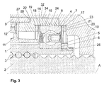
- the Fig. 3 shows a third embodiment of the present invention, in which deviating from Fig. 1 a sleeve 27 is provided for mounting the bearing 4 in the steering housing 9.
- this embodiment corresponds to in Fig. 2 illustrated embodiment.
- Deviating from Fig. 2 has the sleeve 27 in the region of the bearing seat 8 of the bearing 4 on an inwardly facing circumferential ridge 24.
- the embodiment corresponds to Fig. 3 in the region of the bearing seat 8 of the embodiment, the Fig. 1 has been described.
- the assembly advantages due to the sleeve 27 also result in the embodiment Fig. 3 , However, the bearing seat 8 with the circumferential ridge 24 is easier to manufacture than that in Fig. 2 illustrated convex portion in the region of the bearing seat.
- the web 24 is dimensioned sufficiently narrow to allow here also a slight tilting of the bearing 4, if an external dynamic load requires it.
- the rotating components and the sleeve and the inner regions of the steering housing 9 and the housing cover 10 and the sleeve 27 are formed substantially rotationally symmetrical to the longitudinal axis A.
- the sleeve 27 may be made in particular as a turned part.
Landscapes
- Engineering & Computer Science (AREA)
- Mechanical Engineering (AREA)
- General Engineering & Computer Science (AREA)
- Chemical & Material Sciences (AREA)
- Combustion & Propulsion (AREA)
- Transportation (AREA)
- Power Steering Mechanism (AREA)
- Support Of The Bearing (AREA)
- Mounting Of Bearings Or Others (AREA)
- Rolling Contact Bearings (AREA)
Applications Claiming Priority (2)
| Application Number | Priority Date | Filing Date | Title |
|---|---|---|---|
| DE102011116058A DE102011116058A1 (de) | 2011-10-18 | 2011-10-18 | Elektromechanische Kraftfahrzeuglenkung |
| PCT/EP2012/003809 WO2013056770A1 (de) | 2011-10-18 | 2012-09-11 | Elektromechanische kraftfahrzeuglenkung |
Publications (2)
| Publication Number | Publication Date |
|---|---|
| EP2768717A1 EP2768717A1 (de) | 2014-08-27 |
| EP2768717B1 true EP2768717B1 (de) | 2016-06-15 |
Family
ID=47008451
Family Applications (1)
| Application Number | Title | Priority Date | Filing Date |
|---|---|---|---|
| EP12769907.2A Not-in-force EP2768717B1 (de) | 2011-10-18 | 2012-09-11 | Elektromechanische kraftfahrzeuglenkung |
Country Status (7)
| Country | Link |
|---|---|
| US (1) | US9033097B2 (pl) |
| EP (1) | EP2768717B1 (pl) |
| CN (1) | CN103889823B (pl) |
| DE (1) | DE102011116058A1 (pl) |
| ES (1) | ES2591009T3 (pl) |
| PL (1) | PL2768717T3 (pl) |
| WO (1) | WO2013056770A1 (pl) |
Families Citing this family (13)
| Publication number | Priority date | Publication date | Assignee | Title |
|---|---|---|---|---|
| DE102010003105A1 (de) * | 2010-03-22 | 2011-09-22 | Zf Lenksysteme Gmbh | Servolenkung |
| CN103057581A (zh) * | 2011-10-24 | 2013-04-24 | 蒂森克虏伯普利斯坦有限公司 | 机电的机动车转向装置 |
| DE102012005932B4 (de) * | 2012-03-26 | 2018-07-12 | Thyssenkrupp Presta Aktiengesellschaft | Lageranordnung |
| JP6471411B2 (ja) * | 2014-03-26 | 2019-02-20 | 株式会社ジェイテクト | ステアリング装置 |
| DE102014006469B3 (de) * | 2014-05-06 | 2015-07-02 | Thyssenkrupp Presta Ag | Lager für einen Kugelgewindetrieb |
| DE102014007866B4 (de) | 2014-06-03 | 2016-05-04 | Thyssenkrupp Presta Ag | Kunststoffhülse zur Absicherung einer Kugelumlenkung und zur Zentrierung einer Wellfeder und einer Passscheibe in einem Lenkgetriebe |
| DE102014109407A1 (de) | 2014-07-04 | 2016-01-07 | Trw Automotive Gmbh | Servolenkung für Kraftfahrzeuge |
| JP6420184B2 (ja) * | 2015-03-06 | 2018-11-07 | トヨタ自動車株式会社 | 電動パワーステアリング装置 |
| US10274008B2 (en) * | 2015-06-19 | 2019-04-30 | Steering Solutions Ip Holding Corporation | Axial load bearing assembly |
| DE102017221153A1 (de) * | 2017-11-27 | 2019-05-29 | Ford Global Technologies, Llc | Lageranordnung und Lenkgetriebe |
| DE102019201933A1 (de) | 2019-02-14 | 2020-08-20 | Robert Bosch Gmbh | Lenksystem |
| DE102020206429A1 (de) * | 2020-05-25 | 2021-11-25 | Robert Bosch Gesellschaft mit beschränkter Haftung | Lenksystem |
| CN113147885B (zh) * | 2021-05-07 | 2022-08-05 | 徐州重型机械有限公司 | 一种双回路半整体式转向器、转向助力系统及起重机 |
Family Cites Families (13)
| Publication number | Priority date | Publication date | Assignee | Title |
|---|---|---|---|---|
| DE1947337U (de) | 1966-02-26 | 1966-10-06 | Bbc Brown Boveri & Cie | Elastisches waelzlager. |
| US6499369B1 (en) | 1999-09-16 | 2002-12-31 | Delphi Technologies, Inc. | Rack ball nut interface |
| JP2002145080A (ja) | 2000-11-10 | 2002-05-22 | Nsk Ltd | 電動パワーステアリング装置 |
| CN100411934C (zh) | 2002-12-09 | 2008-08-20 | 日本精工株式会社 | 电动助力转向装置 |
| DE10310492A1 (de) | 2003-03-11 | 2004-09-23 | Zf Lenksysteme Gmbh | Servolenkung |
| JP4356485B2 (ja) * | 2004-03-09 | 2009-11-04 | 株式会社ジェイテクト | 電動パワーステアリング装置 |
| DE102004034701A1 (de) | 2004-07-17 | 2006-02-02 | Zf Lenksysteme Gmbh | Wälzlager |
| DE102006037479A1 (de) | 2006-08-10 | 2008-02-14 | Zf Lenksysteme Gmbh | Servolenkung |
| DE102006053244A1 (de) * | 2006-11-11 | 2008-05-15 | Schaeffler Kg | Kugelgewindetrieb |
| EP2409043A4 (en) * | 2009-01-23 | 2013-05-22 | Skf Usa Inc | BEARING ASSEMBLY FOR AN ASSISTED STEERING MECHANISM |
| DE102009000575A1 (de) * | 2009-02-03 | 2010-08-19 | Zf Lenksysteme Gmbh | Elektrische Servolenkung für Kraftfahrzeuge |
| WO2011015374A1 (de) * | 2009-08-06 | 2011-02-10 | Zf Lenksysteme Gmbh | Servolenkung mit vorgespanntem, geteilten lagerring |
| DE102010002958A1 (de) * | 2010-03-17 | 2011-09-22 | Zf Lenksysteme Gmbh | Servolenkung |
-
2011
- 2011-10-18 DE DE102011116058A patent/DE102011116058A1/de not_active Withdrawn
-
2012
- 2012-09-11 CN CN201280051441.3A patent/CN103889823B/zh not_active Expired - Fee Related
- 2012-09-11 EP EP12769907.2A patent/EP2768717B1/de not_active Not-in-force
- 2012-09-11 PL PL12769907.2T patent/PL2768717T3/pl unknown
- 2012-09-11 US US14/346,185 patent/US9033097B2/en active Active
- 2012-09-11 WO PCT/EP2012/003809 patent/WO2013056770A1/de not_active Ceased
- 2012-09-11 ES ES12769907.2T patent/ES2591009T3/es active Active
Non-Patent Citations (1)
| Title |
|---|
| None * |
Also Published As
| Publication number | Publication date |
|---|---|
| CN103889823B (zh) | 2016-10-26 |
| ES2591009T3 (es) | 2016-11-24 |
| DE102011116058A1 (de) | 2013-04-18 |
| EP2768717A1 (de) | 2014-08-27 |
| WO2013056770A1 (de) | 2013-04-25 |
| CN103889823A (zh) | 2014-06-25 |
| PL2768717T3 (pl) | 2016-12-30 |
| US9033097B2 (en) | 2015-05-19 |
| US20140224567A1 (en) | 2014-08-14 |
Similar Documents
| Publication | Publication Date | Title |
|---|---|---|
| EP2986485B1 (de) | Doppelwellfeder mit dämpfender zwischenschicht | |
| WO2013056770A1 (de) | Elektromechanische kraftfahrzeuglenkung | |
| EP2303611B1 (de) | Gelenk- und/oder lageranordnung | |
| EP2651745B1 (de) | Servolenkung mit spindeltrieb | |
| DE102013213708A1 (de) | Schneckengetriebe für eine Lenkhilfevorrichtung eines Kraftfahrzeuges mit Spielausgleich | |
| EP3475146A1 (de) | Kugelgewindetrieb einer elektromechanischen servolenkung mit umlenkkörper für eine kugelrückführung | |
| DE102017209563A1 (de) | Loslager, Lenkgetriebe und Lenksystem | |
| WO2018095639A1 (de) | Lenkgetriebe und lenksystem | |
| DE102012007329A1 (de) | Welle-Nabe-Verbindung | |
| WO2017220715A1 (de) | Kugelgewindetrieb einer elektromechanischen servolenkung mit integriertem schrägkugellager | |
| DE102016122378A1 (de) | Lenksystem | |
| EP4179222B1 (de) | Hilfskraftlenkung für ein kraftfahrzeug | |
| EP3538418B1 (de) | Festlager und lenkgetriebe | |
| WO2024051877A1 (de) | Verstelleinheit einer lenksäule | |
| EP2465752B1 (de) | Servolenkung mit sphärischer Lagerung | |
| EP3496992B1 (de) | Drehlageranordnung für eine lenksäule eines kraftfahrzeugs | |
| DE102015217289B4 (de) | Federbeinlager | |
| DE102016121393A1 (de) | Kugellager und Verfahren zu dessen Herstellung, Festlager, Lenkgetriebe und Lenksystem | |
| DE102021207283B4 (de) | Verstellbarer Wankstabilisator | |
| DE102017119986A1 (de) | Wälzlageranordnung für eine Lenksäule | |
| EP4279357A1 (de) | Lenksystem für ein kraftfahrzeug | |
| WO2018184628A1 (de) | Federbeinlager | |
| DE102018201858B4 (de) | Lenkgetriebe, Lenksystem und Verfahren zur Herstellung eines Schwenkrings für ein Lenkgetriebe | |
| DE102017207708A1 (de) | Festlager, Lenkgetriebe und Lenksystem | |
| DE102019207614A1 (de) | Lenkgetriebe für ein Kraftfahrzeug |
Legal Events
| Date | Code | Title | Description |
|---|---|---|---|
| PUAI | Public reference made under article 153(3) epc to a published international application that has entered the european phase |
Free format text: ORIGINAL CODE: 0009012 |
|
| 17P | Request for examination filed |
Effective date: 20140514 |
|
| AK | Designated contracting states |
Kind code of ref document: A1 Designated state(s): AL AT BE BG CH CY CZ DE DK EE ES FI FR GB GR HR HU IE IS IT LI LT LU LV MC MK MT NL NO PL PT RO RS SE SI SK SM TR |
|
| DAX | Request for extension of the european patent (deleted) | ||
| GRAP | Despatch of communication of intention to grant a patent |
Free format text: ORIGINAL CODE: EPIDOSNIGR1 |
|
| RIC1 | Information provided on ipc code assigned before grant |
Ipc: F16C 27/06 20060101ALI20160310BHEP Ipc: F16C 27/04 20060101ALI20160310BHEP Ipc: F16H 25/24 20060101ALI20160310BHEP Ipc: B62D 5/04 20060101AFI20160310BHEP Ipc: F16C 25/08 20060101ALI20160310BHEP |
|
| INTG | Intention to grant announced |
Effective date: 20160323 |
|
| GRAS | Grant fee paid |
Free format text: ORIGINAL CODE: EPIDOSNIGR3 |
|
| GRAA | (expected) grant |
Free format text: ORIGINAL CODE: 0009210 |
|
| AK | Designated contracting states |
Kind code of ref document: B1 Designated state(s): AL AT BE BG CH CY CZ DE DK EE ES FI FR GB GR HR HU IE IS IT LI LT LU LV MC MK MT NL NO PL PT RO RS SE SI SK SM TR |
|
| REG | Reference to a national code |
Ref country code: CH Ref legal event code: EP Ref country code: GB Ref legal event code: FG4D Free format text: NOT ENGLISH |
|
| REG | Reference to a national code |
Ref country code: IE Ref legal event code: FG4D Free format text: LANGUAGE OF EP DOCUMENT: GERMAN |
|
| REG | Reference to a national code |
Ref country code: AT Ref legal event code: REF Ref document number: 806351 Country of ref document: AT Kind code of ref document: T Effective date: 20160715 |
|
| REG | Reference to a national code |
Ref country code: DE Ref legal event code: R096 Ref document number: 502012007426 Country of ref document: DE |
|
| REG | Reference to a national code |
Ref country code: FR Ref legal event code: PLFP Year of fee payment: 5 |
|
| REG | Reference to a national code |
Ref country code: LT Ref legal event code: MG4D |
|
| REG | Reference to a national code |
Ref country code: NL Ref legal event code: MP Effective date: 20160615 |
|
| PG25 | Lapsed in a contracting state [announced via postgrant information from national office to epo] |
Ref country code: FI Free format text: LAPSE BECAUSE OF FAILURE TO SUBMIT A TRANSLATION OF THE DESCRIPTION OR TO PAY THE FEE WITHIN THE PRESCRIBED TIME-LIMIT Effective date: 20160615 Ref country code: LT Free format text: LAPSE BECAUSE OF FAILURE TO SUBMIT A TRANSLATION OF THE DESCRIPTION OR TO PAY THE FEE WITHIN THE PRESCRIBED TIME-LIMIT Effective date: 20160615 Ref country code: NO Free format text: LAPSE BECAUSE OF FAILURE TO SUBMIT A TRANSLATION OF THE DESCRIPTION OR TO PAY THE FEE WITHIN THE PRESCRIBED TIME-LIMIT Effective date: 20160915 |
|
| REG | Reference to a national code |
Ref country code: ES Ref legal event code: FG2A Ref document number: 2591009 Country of ref document: ES Kind code of ref document: T3 Effective date: 20161124 |
|
| PG25 | Lapsed in a contracting state [announced via postgrant information from national office to epo] |
Ref country code: SE Free format text: LAPSE BECAUSE OF FAILURE TO SUBMIT A TRANSLATION OF THE DESCRIPTION OR TO PAY THE FEE WITHIN THE PRESCRIBED TIME-LIMIT Effective date: 20160615 Ref country code: LV Free format text: LAPSE BECAUSE OF FAILURE TO SUBMIT A TRANSLATION OF THE DESCRIPTION OR TO PAY THE FEE WITHIN THE PRESCRIBED TIME-LIMIT Effective date: 20160615 Ref country code: NL Free format text: LAPSE BECAUSE OF FAILURE TO SUBMIT A TRANSLATION OF THE DESCRIPTION OR TO PAY THE FEE WITHIN THE PRESCRIBED TIME-LIMIT Effective date: 20160615 Ref country code: GR Free format text: LAPSE BECAUSE OF FAILURE TO SUBMIT A TRANSLATION OF THE DESCRIPTION OR TO PAY THE FEE WITHIN THE PRESCRIBED TIME-LIMIT Effective date: 20160916 Ref country code: HR Free format text: LAPSE BECAUSE OF FAILURE TO SUBMIT A TRANSLATION OF THE DESCRIPTION OR TO PAY THE FEE WITHIN THE PRESCRIBED TIME-LIMIT Effective date: 20160615 Ref country code: RS Free format text: LAPSE BECAUSE OF FAILURE TO SUBMIT A TRANSLATION OF THE DESCRIPTION OR TO PAY THE FEE WITHIN THE PRESCRIBED TIME-LIMIT Effective date: 20160615 |
|
| PG25 | Lapsed in a contracting state [announced via postgrant information from national office to epo] |
Ref country code: SK Free format text: LAPSE BECAUSE OF FAILURE TO SUBMIT A TRANSLATION OF THE DESCRIPTION OR TO PAY THE FEE WITHIN THE PRESCRIBED TIME-LIMIT Effective date: 20160615 Ref country code: EE Free format text: LAPSE BECAUSE OF FAILURE TO SUBMIT A TRANSLATION OF THE DESCRIPTION OR TO PAY THE FEE WITHIN THE PRESCRIBED TIME-LIMIT Effective date: 20160615 Ref country code: RO Free format text: LAPSE BECAUSE OF FAILURE TO SUBMIT A TRANSLATION OF THE DESCRIPTION OR TO PAY THE FEE WITHIN THE PRESCRIBED TIME-LIMIT Effective date: 20160615 Ref country code: IS Free format text: LAPSE BECAUSE OF FAILURE TO SUBMIT A TRANSLATION OF THE DESCRIPTION OR TO PAY THE FEE WITHIN THE PRESCRIBED TIME-LIMIT Effective date: 20161015 |
|
| PG25 | Lapsed in a contracting state [announced via postgrant information from national office to epo] |
Ref country code: BE Free format text: LAPSE BECAUSE OF NON-PAYMENT OF DUE FEES Effective date: 20160930 Ref country code: PT Free format text: LAPSE BECAUSE OF FAILURE TO SUBMIT A TRANSLATION OF THE DESCRIPTION OR TO PAY THE FEE WITHIN THE PRESCRIBED TIME-LIMIT Effective date: 20161017 Ref country code: SM Free format text: LAPSE BECAUSE OF FAILURE TO SUBMIT A TRANSLATION OF THE DESCRIPTION OR TO PAY THE FEE WITHIN THE PRESCRIBED TIME-LIMIT Effective date: 20160615 |
|
| REG | Reference to a national code |
Ref country code: DE Ref legal event code: R097 Ref document number: 502012007426 Country of ref document: DE |
|
| PLBE | No opposition filed within time limit |
Free format text: ORIGINAL CODE: 0009261 |
|
| STAA | Information on the status of an ep patent application or granted ep patent |
Free format text: STATUS: NO OPPOSITION FILED WITHIN TIME LIMIT |
|
| PG25 | Lapsed in a contracting state [announced via postgrant information from national office to epo] |
Ref country code: MC Free format text: LAPSE BECAUSE OF FAILURE TO SUBMIT A TRANSLATION OF THE DESCRIPTION OR TO PAY THE FEE WITHIN THE PRESCRIBED TIME-LIMIT Effective date: 20160615 |
|
| REG | Reference to a national code |
Ref country code: CH Ref legal event code: PL |
|
| 26N | No opposition filed |
Effective date: 20170316 |
|
| PG25 | Lapsed in a contracting state [announced via postgrant information from national office to epo] |
Ref country code: DK Free format text: LAPSE BECAUSE OF FAILURE TO SUBMIT A TRANSLATION OF THE DESCRIPTION OR TO PAY THE FEE WITHIN THE PRESCRIBED TIME-LIMIT Effective date: 20160615 |
|
| REG | Reference to a national code |
Ref country code: IE Ref legal event code: MM4A |
|
| PG25 | Lapsed in a contracting state [announced via postgrant information from national office to epo] |
Ref country code: LI Free format text: LAPSE BECAUSE OF NON-PAYMENT OF DUE FEES Effective date: 20160930 Ref country code: CH Free format text: LAPSE BECAUSE OF NON-PAYMENT OF DUE FEES Effective date: 20160930 Ref country code: IE Free format text: LAPSE BECAUSE OF NON-PAYMENT OF DUE FEES Effective date: 20160911 |
|
| PG25 | Lapsed in a contracting state [announced via postgrant information from national office to epo] |
Ref country code: SI Free format text: LAPSE BECAUSE OF FAILURE TO SUBMIT A TRANSLATION OF THE DESCRIPTION OR TO PAY THE FEE WITHIN THE PRESCRIBED TIME-LIMIT Effective date: 20160615 Ref country code: LU Free format text: LAPSE BECAUSE OF NON-PAYMENT OF DUE FEES Effective date: 20160911 |
|
| REG | Reference to a national code |
Ref country code: FR Ref legal event code: PLFP Year of fee payment: 6 |
|
| REG | Reference to a national code |
Ref country code: BE Ref legal event code: MM Effective date: 20160930 |
|
| PG25 | Lapsed in a contracting state [announced via postgrant information from national office to epo] |
Ref country code: HU Free format text: LAPSE BECAUSE OF FAILURE TO SUBMIT A TRANSLATION OF THE DESCRIPTION OR TO PAY THE FEE WITHIN THE PRESCRIBED TIME-LIMIT; INVALID AB INITIO Effective date: 20120911 |
|
| PG25 | Lapsed in a contracting state [announced via postgrant information from national office to epo] |
Ref country code: CY Free format text: LAPSE BECAUSE OF FAILURE TO SUBMIT A TRANSLATION OF THE DESCRIPTION OR TO PAY THE FEE WITHIN THE PRESCRIBED TIME-LIMIT Effective date: 20160615 Ref country code: MK Free format text: LAPSE BECAUSE OF FAILURE TO SUBMIT A TRANSLATION OF THE DESCRIPTION OR TO PAY THE FEE WITHIN THE PRESCRIBED TIME-LIMIT Effective date: 20160615 Ref country code: MT Free format text: LAPSE BECAUSE OF FAILURE TO SUBMIT A TRANSLATION OF THE DESCRIPTION OR TO PAY THE FEE WITHIN THE PRESCRIBED TIME-LIMIT Effective date: 20160615 |
|
| PG25 | Lapsed in a contracting state [announced via postgrant information from national office to epo] |
Ref country code: BG Free format text: LAPSE BECAUSE OF FAILURE TO SUBMIT A TRANSLATION OF THE DESCRIPTION OR TO PAY THE FEE WITHIN THE PRESCRIBED TIME-LIMIT Effective date: 20160615 |
|
| REG | Reference to a national code |
Ref country code: FR Ref legal event code: PLFP Year of fee payment: 7 |
|
| PG25 | Lapsed in a contracting state [announced via postgrant information from national office to epo] |
Ref country code: TR Free format text: LAPSE BECAUSE OF FAILURE TO SUBMIT A TRANSLATION OF THE DESCRIPTION OR TO PAY THE FEE WITHIN THE PRESCRIBED TIME-LIMIT Effective date: 20160615 Ref country code: AL Free format text: LAPSE BECAUSE OF FAILURE TO SUBMIT A TRANSLATION OF THE DESCRIPTION OR TO PAY THE FEE WITHIN THE PRESCRIBED TIME-LIMIT Effective date: 20160615 |
|
| REG | Reference to a national code |
Ref country code: AT Ref legal event code: MM01 Ref document number: 806351 Country of ref document: AT Kind code of ref document: T Effective date: 20170911 |
|
| PG25 | Lapsed in a contracting state [announced via postgrant information from national office to epo] |
Ref country code: AT Free format text: LAPSE BECAUSE OF NON-PAYMENT OF DUE FEES Effective date: 20170911 |
|
| PGFP | Annual fee paid to national office [announced via postgrant information from national office to epo] |
Ref country code: CZ Payment date: 20210913 Year of fee payment: 10 Ref country code: IT Payment date: 20210922 Year of fee payment: 10 |
|
| REG | Reference to a national code |
Ref country code: DE Ref legal event code: R081 Ref document number: 502012007426 Country of ref document: DE Owner name: THYSSENKRUPP PRESTA AKTIENGESELLSCHAFT, LI Free format text: FORMER OWNER: THYSSENKRUPP PRESTA AG, ESCHEN, LI |
|
| PGFP | Annual fee paid to national office [announced via postgrant information from national office to epo] |
Ref country code: PL Payment date: 20210906 Year of fee payment: 10 |
|
| PGFP | Annual fee paid to national office [announced via postgrant information from national office to epo] |
Ref country code: ES Payment date: 20211125 Year of fee payment: 10 |
|
| REG | Reference to a national code |
Ref country code: DE Ref legal event code: R084 Ref document number: 502012007426 Country of ref document: DE |
|
| PG25 | Lapsed in a contracting state [announced via postgrant information from national office to epo] |
Ref country code: CZ Free format text: LAPSE BECAUSE OF NON-PAYMENT OF DUE FEES Effective date: 20220911 |
|
| REG | Reference to a national code |
Ref country code: ES Ref legal event code: FD2A Effective date: 20231027 |
|
| PG25 | Lapsed in a contracting state [announced via postgrant information from national office to epo] |
Ref country code: IT Free format text: LAPSE BECAUSE OF NON-PAYMENT OF DUE FEES Effective date: 20220911 |
|
| PGFP | Annual fee paid to national office [announced via postgrant information from national office to epo] |
Ref country code: GB Payment date: 20230920 Year of fee payment: 12 |
|
| PG25 | Lapsed in a contracting state [announced via postgrant information from national office to epo] |
Ref country code: PL Free format text: LAPSE BECAUSE OF NON-PAYMENT OF DUE FEES Effective date: 20220911 |
|
| PGFP | Annual fee paid to national office [announced via postgrant information from national office to epo] |
Ref country code: FR Payment date: 20230928 Year of fee payment: 12 Ref country code: DE Payment date: 20230920 Year of fee payment: 12 |
|
| PG25 | Lapsed in a contracting state [announced via postgrant information from national office to epo] |
Ref country code: ES Free format text: LAPSE BECAUSE OF NON-PAYMENT OF DUE FEES Effective date: 20220912 |
|
| PG25 | Lapsed in a contracting state [announced via postgrant information from national office to epo] |
Ref country code: ES Free format text: LAPSE BECAUSE OF NON-PAYMENT OF DUE FEES Effective date: 20220912 |
|
| REG | Reference to a national code |
Ref country code: DE Ref legal event code: R119 Ref document number: 502012007426 Country of ref document: DE |
|
| GBPC | Gb: european patent ceased through non-payment of renewal fee |
Effective date: 20240911 |
|
| PG25 | Lapsed in a contracting state [announced via postgrant information from national office to epo] |
Ref country code: DE Free format text: LAPSE BECAUSE OF NON-PAYMENT OF DUE FEES Effective date: 20250401 |
|
| PG25 | Lapsed in a contracting state [announced via postgrant information from national office to epo] |
Ref country code: GB Free format text: LAPSE BECAUSE OF NON-PAYMENT OF DUE FEES Effective date: 20240911 |
|
| PG25 | Lapsed in a contracting state [announced via postgrant information from national office to epo] |
Ref country code: FR Free format text: LAPSE BECAUSE OF NON-PAYMENT OF DUE FEES Effective date: 20240930 |