EP2768754B1 - Dévidoir de ruban - Google Patents
Dévidoir de ruban Download PDFInfo
- Publication number
- EP2768754B1 EP2768754B1 EP12842098.1A EP12842098A EP2768754B1 EP 2768754 B1 EP2768754 B1 EP 2768754B1 EP 12842098 A EP12842098 A EP 12842098A EP 2768754 B1 EP2768754 B1 EP 2768754B1
- Authority
- EP
- European Patent Office
- Prior art keywords
- main plate
- tape
- circumferential wall
- case
- adhesive tape
- Prior art date
- Legal status (The legal status is an assumption and is not a legal conclusion. Google has not performed a legal analysis and makes no representation as to the accuracy of the status listed.)
- Not-in-force
Links
- 238000005520 cutting process Methods 0.000 claims description 10
- 239000003795 chemical substances by application Substances 0.000 claims description 2
- 239000004576 sand Substances 0.000 claims 1
- 239000002390 adhesive tape Substances 0.000 description 62
- 239000000853 adhesive Substances 0.000 description 10
- 238000010586 diagram Methods 0.000 description 9
- 230000001070 adhesive effect Effects 0.000 description 8
- 239000000463 material Substances 0.000 description 5
- 239000000428 dust Substances 0.000 description 4
- 238000005516 engineering process Methods 0.000 description 3
- 238000000034 method Methods 0.000 description 2
- 239000011347 resin Substances 0.000 description 2
- 229920005989 resin Polymers 0.000 description 2
- 238000004804 winding Methods 0.000 description 2
- 239000011248 coating agent Substances 0.000 description 1
- 238000000576 coating method Methods 0.000 description 1
- 238000010276 construction Methods 0.000 description 1
- 230000000694 effects Effects 0.000 description 1
- 238000004049 embossing Methods 0.000 description 1
- 238000004519 manufacturing process Methods 0.000 description 1
- 239000002184 metal Substances 0.000 description 1
- 229920001296 polysiloxane Polymers 0.000 description 1
- 238000005488 sandblasting Methods 0.000 description 1
- 238000000926 separation method Methods 0.000 description 1
Images




Classifications
-
- B—PERFORMING OPERATIONS; TRANSPORTING
- B65—CONVEYING; PACKING; STORING; HANDLING THIN OR FILAMENTARY MATERIAL
- B65H—HANDLING THIN OR FILAMENTARY MATERIAL, e.g. SHEETS, WEBS, CABLES
- B65H35/00—Delivering articles from cutting or line-perforating machines; Article or web delivery apparatus incorporating cutting or line-perforating devices, e.g. adhesive tape dispensers
- B65H35/04—Delivering articles from cutting or line-perforating machines; Article or web delivery apparatus incorporating cutting or line-perforating devices, e.g. adhesive tape dispensers from or with transverse cutters or perforators
- B65H35/06—Delivering articles from cutting or line-perforating machines; Article or web delivery apparatus incorporating cutting or line-perforating devices, e.g. adhesive tape dispensers from or with transverse cutters or perforators from or with blade, e.g. shear-blade, cutters or perforators
-
- B—PERFORMING OPERATIONS; TRANSPORTING
- B65—CONVEYING; PACKING; STORING; HANDLING THIN OR FILAMENTARY MATERIAL
- B65H—HANDLING THIN OR FILAMENTARY MATERIAL, e.g. SHEETS, WEBS, CABLES
- B65H35/00—Delivering articles from cutting or line-perforating machines; Article or web delivery apparatus incorporating cutting or line-perforating devices, e.g. adhesive tape dispensers
- B65H35/0006—Article or web delivery apparatus incorporating cutting or line-perforating devices
- B65H35/002—Hand-held or table apparatus
- B65H35/0026—Hand-held or table apparatus for delivering pressure-sensitive adhesive tape
-
- Y—GENERAL TAGGING OF NEW TECHNOLOGICAL DEVELOPMENTS; GENERAL TAGGING OF CROSS-SECTIONAL TECHNOLOGIES SPANNING OVER SEVERAL SECTIONS OF THE IPC; TECHNICAL SUBJECTS COVERED BY FORMER USPC CROSS-REFERENCE ART COLLECTIONS [XRACs] AND DIGESTS
- Y10—TECHNICAL SUBJECTS COVERED BY FORMER USPC
- Y10T—TECHNICAL SUBJECTS COVERED BY FORMER US CLASSIFICATION
- Y10T225/00—Severing by tearing or breaking
- Y10T225/20—Severing by manually forcing against fixed edge
- Y10T225/238—With housing for work supply
- Y10T225/246—Including special support for wound supply package
Definitions
- exemplary dispensers include those described in JP0176850U and JP012124968U .
- Previous dispensers incorporate a structure that is formed from a case, which houses the tape roll, and a cutter, which is attached on the tape wind/unwind opening provided on one part of the circumferential wall of this case, so that it can be opened and closed.
- the cutter becomes unified as one part with the circumferential wall of the case, and the dispenser becomes one that has a compact shape in the state when it is not being used.
- JP H10157911 (A ) relates to a portable tape cutter.
- a second case is rotatably assembled to a first case of the portable tape cutter.
- An adhesive tape and the second case are supported by a shaft part.
- JP H10120282 (A ) relates to an adhesive tape dispenser.
- the tape dispenser comprises a case body provided with an opening part, a cover member fitted in such a way as to close the case body, and a cutting edge arranged along the opening part.
- the above described tape dispenser according to the previous technology is a dispenser that has desirable compactness properties.
- the front edge of the adhesive tape is held on the cutter through the adhesive agent of the adhesive tape itself.
- the case has a structure that surrounds the whole body of the tape roll, reducing the ability of dust to adhere to the adhesive tape.
- the front edge of the adhesive tape is separated from the cutter and the adhesive tape is back wound in such a construction, it is necessary that the case cover removed and the tape roll is taken out of the case. Also, exchanging a used tape roll for a new one similarly takes time and effort.
- the present disclosure provides a tape dispenser, which while maintaining the compactness properties highlighted above, has improved operational properties.
- the tape dispenser includes a case that houses the tape roll and is provided with the first and second main plates that are placed at a uniform distance.
- the two main plates are mutually connected so they can rotate relative to one another.
- a circumferential wall is provided in the gap between the first and the second main plates, and the circumferential wall, in its circumferential direction, is divided into the first and second circumferential wall parts, which are correspondingly formed as one body with the first and second main plates.
- a supporting axis which is provided one of the main plates, supports the free rotation of the tape roll within the case.
- a cutter blade is provided on a circumferential wall part and is typically proximate a substantially arc shaped support surface.
- the present disclosure provides a tape dispenser comprising a case operable to house a tape roll, the case including a first main plate, a second main plate spaced from the first main plate and rotatably connected to the first main plate, a circumferential wall between the first main plate and the second main plate, wherein the circumferential wall is divided along its circumferential direction into a first circumferential wall portion and second circumferential wall portion, wherein the first circumferential wall portion is integral with the first main plate, and the circumferential wall portion is integral with the second main plate, a supporting axis extending from one of the first or second main plate in the direction of the opposing main plate, and a cutter blade disposed on one of the first and second circumferential wall portions.
- a As used herein, "a,” “an,” “the,” “at least one,” and “one or more” are used interchangeably. Thus, for example, a label remover comprising “a” microblade may be considered to include “one or more” microblades.
- a tape dispenser according to a first embodiment of the present invention will be described.
- the tape dispenser according to this implementation it is a dispenser where a case, which houses a tape roll whose structure is formed as an adhesive tape is wound in a roll shape, is provided, and the adhesive tape that is unwound from the tape roll can be cut by this dispenser.
- the case is characterized by the fact that it is equipped with the first main plate, the second main plate, which is placed at a certain gap from this main plate, a circumferential wall provided in the space between the main plate and the main plate, and a supporting axis, which is used in order to support the tape roll so it can freely rotate and which is provided on either of the main plate or the main plate and extends facing the other main plate, and regarding the circumferential wall, which mutually connects the main plate and the main plate, so they can move, it is divided along its circumferential direction into a circumferential wall part and circumferential wall part, and the circumferential wall part is formed as one body with the main plate, and the circumferential wall part is formed as one body with the main plate, and on either one of the circumferential part or the circumferential part a cutter blade is provided.
- rotating the main plate relative to the other main plate causes the separated circumferential wall portions to be opened together with the main plate rotation, which in turn at least partially exposes the cutter blade provided on one of the circumferential wall parts.
- the circumferential surface of the tape roll becomes widely exposed and it becomes easy to view and grasp the circumferential surface of the tape roll.
- the supporting axis that is provided on one of the main plates also moves so that is located at a distance from the inner surface of the other main plate. In that case the exchange of the tape roll becomes easier due to the lack of an opposing plate.
- a substantially arc-shaped tape supporting surface can be provided on the back surface side of the cutter blade.
- the adhesive tape can adhere to such a supporting surface and accordingly prevent the back winding of the adhesive tape toward the tape roll.
- the support surface further provides contact area to ease the tearing of tape across the cutter blade.
- the supporting axis is provided on the first main plate and the cutter blade is provided on the second circumferential wall part.
- rotation of the main plate relative to the other main plate causes the distance between the tape roll attached to the supporting axis and the cutter blade to substantially increase and making it easier to pull out a length of adhesive tape between the cutter blade and the tape roll.
- one or more protrusions can be provided for the supporting axis.
- the protrusion can control the movement of the supporting axis beyond a certain point relative to the opposing main plate, allowing a user to maintain the case in an opened state while limiting the excessive rotation of the main plates.
- the circumferential surface of the tape roll can be easily accessed because the circumferential wall can be opened in the circumferential direction. Consequently, even if the adhesive tape is back wound on the tape roll, it is possible to easily grasp the front end of the adhesive tape and unwind it from the tape roll. Furthermore, through the relative rotational position of the first main plate and the second main plate, it is possible to eliminate the interference with the tape roll attached on the supporting axis, and it becomes easy to exchange the tape roll.
- the tape dispensers of present disclosure provide compactness at the time of use while still allowing for recourse to unintentionally back wound adhesive tape and easier exchange of the tape roll. Furthermore, in the state where the case is closed, the tape roll is enclosed by the main plates and the circumferential wall and because of that also the tape roll is protected from dust, etc.
- Figures 1 and 2 are three-dimensional diagrams of a first implementation of a tape dispenser 10 including a case 12 according to the present disclosure.
- Figure 1 shows the case 12 in a closed state and
- Figure 2 shows the case 12 in an opened state.
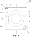
- Figures 3 and 4 depict the tape dispenser 10 in a use state where the tape roll 16, including an adhesive tape 14 wound in a roll shape around a core, has been installed in the tape dispenser 10.
- the tape dispenser 10 includes the case 12 to house the tape roll 16.
- the case 12 includes mutually parallel first main plate 18 and second main plate 20 placed at a certain (typically constant) gap.
- the first main plate 18 and the second main plate 20 are essentially the same size and shape, and as depicted in Figures 1 to 8 they are generally square shaped.
- the shape of the horizontal surface of the main plates is not limited to a square shape. For example, rectangular shape, triangular shapes, pentagram shapes, hexagram shapes, and other multigram type shapes are likewise suitable. Circular shapes, oval shapes, U letter shapes, or shapes formed by the partial extension of these shapes, etc are also contemplated.
- the case 12 includes side plates 22, 24, 26 and 28 that cooperate to form a circumferential wall between the main plates 18 and 20.
- the first main plate 18, the second main plate 20 and the side plates 22 - 28 cooperate to define an interior space that houses the tape roll 16.
- two side plates 26, 28 are formed as one body with the first main plate 18 and define a first circumferential wall section.
- the other two side plates 22, 24 are formed as one body with the second main plate 20 and define a second circumferential wall section. Consequently, it is understood that the circumferential wall of the case 12, which wall is formed from the four side plates 22, 24, 26 and 28 is divided into two circumferential wall sections.
- the first and second main plates 18, 20 are mutually connected through a rotation axis 34, so that the main plates (and circumferential wall sections) are rotatable relative to one another. Consequently, the case 12 of the tape dispenser 10 can be opened as shown in Figure 2 and Figure 3 .
- a cutter blade 36 which is used to cut the adhesive tape 14, is provided on the edge part of the side plate 22.
- the edge part of the side plate 28, including shroud 30, can extend over the cutter blade 36 when the case 12 is closed, so that the blade is not exposed.
- the cutter blade 36 can be formed from a material that is different than that of the second main plate 22; for example, it can be formed from a metal or another type resin material. It can be preferred in certain circumstances that the cutter blade 36 be formed as one body with the side plate 22. By forming the cutter blade 36 and the side plate 22 as one body, it is possible to decrease the process and material costs.
- the cylindrically shaped supporting axis 38 which is used for supporting the free rotation of the tape roll 16, is formed as one body.
- the free end of the supporting axis 38 extends to a position where it engages the inner surface of the second main plate 20.
- Figure 5 is a three-dimensional diagram showing the inner surface of the second main plate 20 and of the side plates 22, 24.
- Two protrusions 40, 42 extend outwardly from the inner surface of the second main plate 20.
- the free end of the supporting axis 38 can engage the space between these protrusions 40, 42 and thereby secure the case 12 is an open position.
- the height of these protrusions 40, 42 is relatively low and by applying a predetermined force, the free end of the supporting axis 38 can surmount the protrusions 40, 42 and the first main plate 18 and the second main plate 20 can rotate further (see, e.g., Figure 7a ).
- the protrusions 40, 42 can function as stoppers to prevent the tape roll 16 from falling off of support axis 38 as the first main plate 18 is moved significantly from the second main plate 20. In certain implementations, only one protrusion may be used to prevent the tape roll from falling off of the support axis 38 during movement.
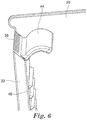
- a tape supporting surface 44 be formed proximate the back surface side of the cutter blade 36.
- the tape supporting surface 44 becomes an intersection point at the time of the cutting of the adhesive tape 14, providing support to a user's attempt to cut the tape. Securing a portion of dispensed adhesive tape to the supporting surface 44 can also help to prevent back winding of that adhesive tape 14 on the tape roll 16.
- the supporting surface 44 it is desirable for the supporting surface 44 to include a cross section along the surface parallel to the first and second main plates 18, 20 that is arc shaped or at least substantially arc shaped.
- the relationship between the extension direction of the tape that can be extended from the tape roll and the position of the cutter blade is almost always constant. Given that relationship, a supporting surface having an almost parallel flat plate surface is typically used.
- the first main plate 18 can rotate relative to the second main plate 20 using the rotational axis 34 as its center. Because of that, the center position of the tape roll 16 changes with the rotation of the first main plate 18.
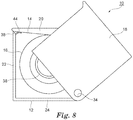
- the position of the tape roll at the time when the user cuts the adhesive tape 14 is not necessarily constant, and the tape extension direction at the time when the user cuts the adhesive tape 14 (in Figure 7 , the extension direction of the adhesive tape indicated as 14'), varies depending on the rotational position.
- a length of adhesive tape also typically extends in a direction on a line continuing from center axis of the tape roll, however, because the tape roll 16 is supported by the supporting axis 38 so that it can freely rotate, the position of the separation start point of the adhesive tape 14 from the tape roll 16 (according to Figure 7 , the intersection point between the adhesive tape 14' and the tape roll 16) varies.
- the tape supporting surface 44 in the depicted embodiment is made to be at least a substantially arc shaped surface and accordingly at least a portion of the extended adhesive tape 14 comes in contact with the tape supporting surface 44 at any rotational angle at which the extended adhesive tape 14 is cut by the cutter blade 36. It is therefore possible for the adhesive tape 14 to regularly achieve sufficient contact surface area relative to the tape support surface 44, and as a result, it is possible to achieve stable and repeated cutting irrespective of the rotational angle and protect the adhesive tape 14 by the tape supporting surface 44 after cutting.
- Exemplary curvatures for the tape supporting surface 44 include a curvature diameter in the range of 5 mm - 20 mm, more preferably, in the range of 8 mm - 12 mm, and the length of the arc is in the range of 2 mm - 10 mm, and more desirably in the range of 3 mm - 5 mm.
- the height of the support surface 44 apex be the same as the height of the cutter blade 36 or at most a slightly greater height.
- One or more protrusions 46 can be provided on the inner surface of the side plate 22 below the cutter blade 36. At the time when the tape roll is housed (as in Figure 4 ), it is possible that portion of adhesive tape 14 can adhere on the inner surface of the case 12, however, such adhesion can be suppressed or reduced through the protrusion 46. It may be preferred in certain implementations that the protrusions 46 repeat along the entire the inner surface of the side plate 22. In other embodiments, the protrusions may repeat over only a portion of the inner surface.
- the present disclosure also provides a method of use and application of a tape dispenser 10 with the above described structure.
- the tape roll 16 is installed on the supporting axis 38, and the front end of the adhesive tape 14 is adhered onto the tape supporting surface 44.
- the tape roll may be installed by the supplier of the case 12 or the user.
- the case 12 is opened from the state shown in Figure 1 , through the state shown in Figure 2 and finishing with the state shown in Figure 3 .
- the free end of the supporting axis 38 comes in contact with and engages the inner surface of the second main plate 20, and accordingly becomes mutually supported by the first main plate 18 and the second main plate 20, thereby allowing for stable, one handed operation.
- the adhesive tape 14 bridges the space between the tape supporting surface 44 and the tape roll 16.
- the space is at least partially or substantially exposed, as shown by the symbol S in Figure 3 , and it is thus possible to easily pull out the adhesive tape 14 with a finger.
- the free end of the supporting axis 38 can be enclosed in the space between the two protrusions 40 and 42, obviating the need to hold the dispenser tightly to prevent further rotation.
- the tape dispenser 10 may be opened (i.e., rotated) beyond the state shown in Figure 3 if desired.
- the first main plate 18 can rotate to 90 degree angle relative to the second main plate 20 (e.g., Figure 7 (a) ), which results in the side plate 24 and the side plate 26 being arranged in a linear fashion to provide a continuous, planar surface. It is thereafter possible to place on the arranged side plates on a flat surface (e.g., table, desk, etc.). Consequently, the tape dispenser 10 can also be used the same way as prior table top type tape dispensers.
- the adhesive tape 14 is separated from the tape supporting surface 44 and it is unwound from the tape roll 16.
- the user pulls a determined length of adhesive tape beyond the cutter blade 36.
- the adhesive tape 14 again adheres on the tape supporting surface 44 and accordingly it is possible to cut the adhesive tape 14 using a light and/or reduced force.
- the rotational angle of the first main plate 18 relative to the second main plate 20 it remains possible to cut the adhesive tape 14 stably and repeatedly, as well as support the adhesive tape 14 through the tape support surface 44 after cutting.
- the diameter of the tape roll becomes smaller, and the exit location of the adhesive tape 14 is changed, however, it remains possible to stably support the adhesive tape 14 irrespective of the tilt angle of the adhesive tape 14 due to the shape of the tape support surface 44.
- the case 12 When the user is finished dispensing adhesive tape, the case 12 is returned to the closed state shown in Figure 1 and Figure 4 . In that state, the tape roll 16 is housed entirely in the case 12. This enclosed housing configuration thus reduces dust adhesion to the tape roll 16 and helps to prevent other unwanted damage during, e.g., transport of the dispenser 10.
- the unwound adhesive tape 14 between the tape roll 16 and the support surface 44 enters a relaxed state as shown in Figure 4 .
- the adhesive surface of the tape 14 can adhere to the inner surface of the side plate 22.
- the inner surface of the side plate 22 is flat, substantial portions of adhesive tape 14 can adhere to the side plate 22, and the adhesive between the two becomes relatively large.
- a plurality of protrusions 46 can be provided on the inner surface of the side plate 22.
- the protrusions 46 reduce the contact surface area with the adhesive surface of the tape 14 and the adhesive force of the adhesive tape 14 is reduced or minimized. Due to less adhesive force between the adhesive surface and the protrusions 46, the adhesive tape 14 can be easily separated from the side plate 22 before subsequent use.
- Additional means of controlling the adhesive force of the adhesive tape 14 relative to the side plate 22, include, but are not limited to, providing numerous small protrusions, subjecting the inner surface of the side plate 22 to sand blasting or embossing processing, or coating by using a silicone type release agent. Also, the position of the application of adhesive force control means is not limited to the inner surface of the side plate 22, and as long as it can contact the adhesive agent surface of the adhesive tape 14 it is a suitable option.
- the tape roll 16 can be easily exchanged by rotating the first main plate 18 relative to the second main plate 20 and exposing the supporting axis 38 and the tape roll core. It is also possible, once a new core is installed on the supporting axis 38, to easily grasp and pull out the edge of the adhesive tape 14. The rotation of first main plate 18 relative to second main plate 20 further allows the user to recover back wound tape that has not remained adhered to the support surface 44.
- the supporting axis 38 is provided in the second main plate 20.
- the adhesive tape 14 that hangs from the tape roll 16 to the cutter blade 36 becomes short.
- the circumferential surface of the tape roll 16 and the adhesive tape 14 are widely exposed, and accordingly the access to the tape is easy, and there are no unfavorable conditions relative to the access such as those according to the previous technology.
Landscapes
- Adhesive Tape Dispensing Devices (AREA)
Claims (3)
- Distributeur de ruban (10) comprenant un boîtier (12) pouvant fonctionner pour loger un rouleau de ruban (16), le boîtier comprenant :une première plaque principale (18),une seconde plaque principale (20) espacée de la première plaque principale et reliée en rotation à la première plaque principale,une paroi circonférentielle entre la première plaque principale et la seconde plaque principale, dans lequel la paroi circonférentielle est divisée le long de sa direction circonférentielle en une première portion de paroi circonférentielle (26 ; 28) et une seconde portion de paroi circonférentielle (22 ; 24), dans lequel la première portion de paroi circonférentielle est solidaire de la première plaque principale et la seconde portion de paroi circonférentielle est solidaire de la seconde plaque principale,un axe de support (38) s'étendant depuis la première plaque principale dans la direction de la seconde plaque principale,une lame de coupe (36) disposée sur la seconde portion de paroi circonférentielle etune surface de support (44) sensiblement en forme d'arc disposée sur la seconde portion de paroi circonférentielle à proximité de la lame de coupe,caractérisé en ce que la surface interne de la seconde portion de paroi circonférentielle comprend une ou plusieurs saillies (46), une surface sablée, une surface gaufrée ou un agent de libération.
- Distributeur de ruban selon la revendication 1, dans lequel l'axe de support s'étend depuis la première plaque principale et inclut une extrémité libre, dans lequel l'extrémité libre est en contact et en prise avec la surface de la seconde plaque principale et dans lequel la seconde plaque principale comprend une saillie (42) pouvant être reliée à l'extrémité libre afin de limiter le mouvement de l'axe de support.
- Distributeur de ruban selon la revendication 1, comprenant en outre un rouleau de ruban disposé sur l'axe de support, dans lequel la première plaque principale et les portions de paroi circonférentielle correspondantes peuvent tourner par rapport à la seconde plaque principale pour exposer au moins une portion du rouleau de ruban.
Applications Claiming Priority (2)
| Application Number | Priority Date | Filing Date | Title |
|---|---|---|---|
| JP2011231710A JP6016348B2 (ja) | 2011-10-21 | 2011-10-21 | テープディスペンサー |
| PCT/US2012/059803 WO2013059072A1 (fr) | 2011-10-21 | 2012-10-11 | Dévidoir de ruban |
Publications (3)
| Publication Number | Publication Date |
|---|---|
| EP2768754A1 EP2768754A1 (fr) | 2014-08-27 |
| EP2768754A4 EP2768754A4 (fr) | 2015-08-12 |
| EP2768754B1 true EP2768754B1 (fr) | 2016-12-14 |
Family
ID=48141257
Family Applications (1)
| Application Number | Title | Priority Date | Filing Date |
|---|---|---|---|
| EP12842098.1A Not-in-force EP2768754B1 (fr) | 2011-10-21 | 2012-10-11 | Dévidoir de ruban |
Country Status (8)
| Country | Link |
|---|---|
| US (1) | US9802781B2 (fr) |
| EP (1) | EP2768754B1 (fr) |
| JP (1) | JP6016348B2 (fr) |
| KR (1) | KR101972503B1 (fr) |
| CN (1) | CN103889870B (fr) |
| BR (1) | BR112014009630A2 (fr) |
| CA (1) | CA2853067A1 (fr) |
| WO (1) | WO2013059072A1 (fr) |
Families Citing this family (3)
| Publication number | Priority date | Publication date | Assignee | Title |
|---|---|---|---|---|
| JP6388385B2 (ja) * | 2014-08-20 | 2018-09-12 | キヤノン株式会社 | 液体吐出ヘッドおよび液体吐出ヘッドの製造方法 |
| USD903747S1 (en) * | 2019-08-06 | 2020-12-01 | Component Storage Innovations Llc | Dispenser for surface mount tape |
| TWM609651U (zh) * | 2020-12-25 | 2021-03-21 | 久年塑膠有限公司 | 膠帶台 |
Family Cites Families (21)
| Publication number | Priority date | Publication date | Assignee | Title |
|---|---|---|---|---|
| US2678777A (en) * | 1953-03-17 | 1954-05-18 | Rexel Products Of Canada Ltd | Sensitive pressure tape dispenser |
| US3102671A (en) * | 1962-03-05 | 1963-09-03 | Johnson & Johnson | Tape dispenser |
| US4447281A (en) * | 1982-09-30 | 1984-05-08 | Joy Richard L | Dispenser for applying adhesive tape |
| JPS6476850A (en) | 1987-09-16 | 1989-03-22 | Sachiko Kosaka | Shoes for knee joint disease patient |
| JPH0176850U (fr) | 1987-11-12 | 1989-05-24 | ||
| JPH02124968U (fr) | 1989-03-23 | 1990-10-15 | ||
| JPH0312852A (ja) | 1989-06-12 | 1991-01-21 | Ricoh Co Ltd | イジェクト禁止機構 |
| CN1088866A (zh) * | 1992-12-29 | 1994-07-06 | 林世钦 | 胶带自动粘切器 |
| JPH08310714A (ja) * | 1995-05-16 | 1996-11-26 | Tombow Pencil Co Ltd | 塗布具容器 |
| FR2750685B1 (fr) * | 1996-07-05 | 1998-10-16 | Smartech | Boite devidoir pour ruban, en particulier pour ruban adhesif |
| JP3018994B2 (ja) | 1996-07-30 | 2000-03-13 | コクヨ株式会社 | 粘着テープディスペンサ |
| JP2914327B2 (ja) * | 1996-10-21 | 1999-06-28 | コクヨ株式会社 | 粘着テープディスペンサ |
| JPH10157911A (ja) * | 1996-11-28 | 1998-06-16 | Nichiban Co Ltd | 携帯用テープカッター |
| TW593067B (en) * | 2000-11-14 | 2004-06-21 | Henkel Kgaa | Apparatus for dispensing a roll of material |
| CN2542629Y (zh) * | 2002-04-28 | 2003-04-02 | 上海北极熊文具胶带有限公司 | 最新精致胶纸器 |
| JP4258802B2 (ja) * | 2003-03-13 | 2009-04-30 | ニチバン株式会社 | 粘着テープ収納カッター |
| CN2763232Y (zh) * | 2004-12-17 | 2006-03-08 | 郑永柱 | 胶带切割器 |
| JP2006232461A (ja) | 2005-02-24 | 2006-09-07 | Sumio Asayama | 粘着巻きテープカッター |
| JP2007137601A (ja) | 2005-11-18 | 2007-06-07 | Asahitekku Corporation:Kk | テープカッター |
| JP3129973U (ja) | 2006-12-25 | 2007-03-08 | 張基財 | テープカッターの構造 |
| US20090230163A1 (en) * | 2008-03-13 | 2009-09-17 | Chi-Tsai Chang | Adhesive tape dispenser |
-
2011
- 2011-10-21 JP JP2011231710A patent/JP6016348B2/ja not_active Expired - Fee Related
-
2012
- 2012-10-11 US US14/353,078 patent/US9802781B2/en not_active Expired - Fee Related
- 2012-10-11 KR KR1020147013327A patent/KR101972503B1/ko not_active Expired - Fee Related
- 2012-10-11 WO PCT/US2012/059803 patent/WO2013059072A1/fr not_active Ceased
- 2012-10-11 CN CN201280051711.0A patent/CN103889870B/zh not_active Expired - Fee Related
- 2012-10-11 CA CA 2853067 patent/CA2853067A1/fr not_active Abandoned
- 2012-10-11 EP EP12842098.1A patent/EP2768754B1/fr not_active Not-in-force
- 2012-10-11 BR BR112014009630A patent/BR112014009630A2/pt active Search and Examination
Also Published As
| Publication number | Publication date |
|---|---|
| CN103889870B (zh) | 2016-08-17 |
| JP2013086954A (ja) | 2013-05-13 |
| BR112014009630A2 (pt) | 2017-06-13 |
| KR20140084212A (ko) | 2014-07-04 |
| US20140284367A1 (en) | 2014-09-25 |
| JP6016348B2 (ja) | 2016-10-26 |
| WO2013059072A1 (fr) | 2013-04-25 |
| EP2768754A4 (fr) | 2015-08-12 |
| CA2853067A1 (fr) | 2013-04-25 |
| EP2768754A1 (fr) | 2014-08-27 |
| KR101972503B1 (ko) | 2019-04-25 |
| CN103889870A (zh) | 2014-06-25 |
| US9802781B2 (en) | 2017-10-31 |
Similar Documents
| Publication | Publication Date | Title |
|---|---|---|
| AU2002219917B2 (en) | Hand-held adhesive tape dispenser | |
| US8943938B2 (en) | Dispenser | |
| US9802781B2 (en) | Tape dispenser | |
| EP2564820A1 (fr) | Lunettes industrielles | |
| WO1999054245A1 (fr) | Devidoir de bande adhesive | |
| US20160280498A1 (en) | Tape dispenser | |
| US7178707B1 (en) | Surgical tape dispenser | |
| US10005633B2 (en) | Dispensers | |
| KR101918134B1 (ko) | 롤 제품용 스핀들 및 분배기와 그의 제조 및 이용 방법 | |
| US7322543B2 (en) | Party streamer dispenser | |
| US20050056676A1 (en) | Adhesive tape cutter | |
| US20050284583A1 (en) | One handed spool and roller tape dispenser | |
| CA2472772C (fr) | Dispositif distributeur de morceaux de ruban adhesif a deux faces, et rouleau de recharge pour le dispositif | |
| EP1183203B1 (fr) | Devidoir pour emballage | |
| US3147897A (en) | Tape dispenser | |
| JP3080598B2 (ja) | マスキングフィルムロール用のカッター付きホルダ | |
| CN218261091U (zh) | 一种翻转切刀机构 | |
| KR200423924Y1 (ko) | 접착테이프 홀더 | |
| JP6395964B1 (ja) | ローラー型清掃具 | |
| US2757449A (en) | Continuous-blade razor | |
| TW201420477A (zh) | 具有整合膠帶心軸之膠帶捲筒的施配器 | |
| KR200179000Y1 (ko) | 테이프 오염을 줄인 부착식 테이프 디스펜서 | |
| JP2002052491A (ja) | 貼付け式バランスウェイト用カッター | |
| JP2003146529A (ja) | テープカッター |
Legal Events
| Date | Code | Title | Description |
|---|---|---|---|
| PUAI | Public reference made under article 153(3) epc to a published international application that has entered the european phase |
Free format text: ORIGINAL CODE: 0009012 |
|
| 17P | Request for examination filed |
Effective date: 20140429 |
|
| AK | Designated contracting states |
Kind code of ref document: A1 Designated state(s): AL AT BE BG CH CY CZ DE DK EE ES FI FR GB GR HR HU IE IS IT LI LT LU LV MC MK MT NL NO PL PT RO RS SE SI SK SM TR |
|
| DAX | Request for extension of the european patent (deleted) | ||
| RA4 | Supplementary search report drawn up and despatched (corrected) |
Effective date: 20150714 |
|
| RIC1 | Information provided on ipc code assigned before grant |
Ipc: B65H 35/00 20060101ALI20150708BHEP Ipc: B65H 35/07 20060101AFI20150708BHEP |
|
| GRAP | Despatch of communication of intention to grant a patent |
Free format text: ORIGINAL CODE: EPIDOSNIGR1 |
|
| RIC1 | Information provided on ipc code assigned before grant |
Ipc: B65H 35/07 20060101AFI20160527BHEP Ipc: B65H 35/00 20060101ALI20160527BHEP |
|
| INTG | Intention to grant announced |
Effective date: 20160617 |
|
| STAA | Information on the status of an ep patent application or granted ep patent |
Free format text: STATUS: GRANT OF PATENT IS INTENDED |
|
| GRAS | Grant fee paid |
Free format text: ORIGINAL CODE: EPIDOSNIGR3 |
|
| GRAA | (expected) grant |
Free format text: ORIGINAL CODE: 0009210 |
|
| STAA | Information on the status of an ep patent application or granted ep patent |
Free format text: STATUS: THE PATENT HAS BEEN GRANTED |
|
| AK | Designated contracting states |
Kind code of ref document: B1 Designated state(s): AL AT BE BG CH CY CZ DE DK EE ES FI FR GB GR HR HU IE IS IT LI LT LU LV MC MK MT NL NO PL PT RO RS SE SI SK SM TR |
|
| REG | Reference to a national code |
Ref country code: GB Ref legal event code: FG4D |
|
| REG | Reference to a national code |
Ref country code: CH Ref legal event code: EP |
|
| REG | Reference to a national code |
Ref country code: IE Ref legal event code: FG4D |
|
| REG | Reference to a national code |
Ref country code: AT Ref legal event code: REF Ref document number: 853359 Country of ref document: AT Kind code of ref document: T Effective date: 20170115 |
|
| REG | Reference to a national code |
Ref country code: DE Ref legal event code: R096 Ref document number: 602012026718 Country of ref document: DE |
|
| PG25 | Lapsed in a contracting state [announced via postgrant information from national office to epo] |
Ref country code: LV Free format text: LAPSE BECAUSE OF FAILURE TO SUBMIT A TRANSLATION OF THE DESCRIPTION OR TO PAY THE FEE WITHIN THE PRESCRIBED TIME-LIMIT Effective date: 20161214 |
|
| REG | Reference to a national code |
Ref country code: LT Ref legal event code: MG4D |
|
| REG | Reference to a national code |
Ref country code: NL Ref legal event code: MP Effective date: 20161214 |
|
| PG25 | Lapsed in a contracting state [announced via postgrant information from national office to epo] |
Ref country code: SE Free format text: LAPSE BECAUSE OF FAILURE TO SUBMIT A TRANSLATION OF THE DESCRIPTION OR TO PAY THE FEE WITHIN THE PRESCRIBED TIME-LIMIT Effective date: 20161214 Ref country code: LT Free format text: LAPSE BECAUSE OF FAILURE TO SUBMIT A TRANSLATION OF THE DESCRIPTION OR TO PAY THE FEE WITHIN THE PRESCRIBED TIME-LIMIT Effective date: 20161214 Ref country code: GR Free format text: LAPSE BECAUSE OF FAILURE TO SUBMIT A TRANSLATION OF THE DESCRIPTION OR TO PAY THE FEE WITHIN THE PRESCRIBED TIME-LIMIT Effective date: 20170315 Ref country code: NO Free format text: LAPSE BECAUSE OF FAILURE TO SUBMIT A TRANSLATION OF THE DESCRIPTION OR TO PAY THE FEE WITHIN THE PRESCRIBED TIME-LIMIT Effective date: 20170314 |
|
| REG | Reference to a national code |
Ref country code: AT Ref legal event code: MK05 Ref document number: 853359 Country of ref document: AT Kind code of ref document: T Effective date: 20161214 |
|
| PG25 | Lapsed in a contracting state [announced via postgrant information from national office to epo] |
Ref country code: HR Free format text: LAPSE BECAUSE OF FAILURE TO SUBMIT A TRANSLATION OF THE DESCRIPTION OR TO PAY THE FEE WITHIN THE PRESCRIBED TIME-LIMIT Effective date: 20161214 Ref country code: RS Free format text: LAPSE BECAUSE OF FAILURE TO SUBMIT A TRANSLATION OF THE DESCRIPTION OR TO PAY THE FEE WITHIN THE PRESCRIBED TIME-LIMIT Effective date: 20161214 Ref country code: FI Free format text: LAPSE BECAUSE OF FAILURE TO SUBMIT A TRANSLATION OF THE DESCRIPTION OR TO PAY THE FEE WITHIN THE PRESCRIBED TIME-LIMIT Effective date: 20161214 |
|
| PG25 | Lapsed in a contracting state [announced via postgrant information from national office to epo] |
Ref country code: NL Free format text: LAPSE BECAUSE OF FAILURE TO SUBMIT A TRANSLATION OF THE DESCRIPTION OR TO PAY THE FEE WITHIN THE PRESCRIBED TIME-LIMIT Effective date: 20161214 |
|
| PG25 | Lapsed in a contracting state [announced via postgrant information from national office to epo] |
Ref country code: SK Free format text: LAPSE BECAUSE OF FAILURE TO SUBMIT A TRANSLATION OF THE DESCRIPTION OR TO PAY THE FEE WITHIN THE PRESCRIBED TIME-LIMIT Effective date: 20161214 Ref country code: EE Free format text: LAPSE BECAUSE OF FAILURE TO SUBMIT A TRANSLATION OF THE DESCRIPTION OR TO PAY THE FEE WITHIN THE PRESCRIBED TIME-LIMIT Effective date: 20161214 Ref country code: IS Free format text: LAPSE BECAUSE OF FAILURE TO SUBMIT A TRANSLATION OF THE DESCRIPTION OR TO PAY THE FEE WITHIN THE PRESCRIBED TIME-LIMIT Effective date: 20170414 Ref country code: RO Free format text: LAPSE BECAUSE OF FAILURE TO SUBMIT A TRANSLATION OF THE DESCRIPTION OR TO PAY THE FEE WITHIN THE PRESCRIBED TIME-LIMIT Effective date: 20161214 Ref country code: CZ Free format text: LAPSE BECAUSE OF FAILURE TO SUBMIT A TRANSLATION OF THE DESCRIPTION OR TO PAY THE FEE WITHIN THE PRESCRIBED TIME-LIMIT Effective date: 20161214 |
|
| PG25 | Lapsed in a contracting state [announced via postgrant information from national office to epo] |
Ref country code: PT Free format text: LAPSE BECAUSE OF FAILURE TO SUBMIT A TRANSLATION OF THE DESCRIPTION OR TO PAY THE FEE WITHIN THE PRESCRIBED TIME-LIMIT Effective date: 20170414 Ref country code: IT Free format text: LAPSE BECAUSE OF FAILURE TO SUBMIT A TRANSLATION OF THE DESCRIPTION OR TO PAY THE FEE WITHIN THE PRESCRIBED TIME-LIMIT Effective date: 20161214 Ref country code: BG Free format text: LAPSE BECAUSE OF FAILURE TO SUBMIT A TRANSLATION OF THE DESCRIPTION OR TO PAY THE FEE WITHIN THE PRESCRIBED TIME-LIMIT Effective date: 20170314 Ref country code: ES Free format text: LAPSE BECAUSE OF FAILURE TO SUBMIT A TRANSLATION OF THE DESCRIPTION OR TO PAY THE FEE WITHIN THE PRESCRIBED TIME-LIMIT Effective date: 20161214 Ref country code: AT Free format text: LAPSE BECAUSE OF FAILURE TO SUBMIT A TRANSLATION OF THE DESCRIPTION OR TO PAY THE FEE WITHIN THE PRESCRIBED TIME-LIMIT Effective date: 20161214 Ref country code: SM Free format text: LAPSE BECAUSE OF FAILURE TO SUBMIT A TRANSLATION OF THE DESCRIPTION OR TO PAY THE FEE WITHIN THE PRESCRIBED TIME-LIMIT Effective date: 20161214 Ref country code: BE Free format text: LAPSE BECAUSE OF FAILURE TO SUBMIT A TRANSLATION OF THE DESCRIPTION OR TO PAY THE FEE WITHIN THE PRESCRIBED TIME-LIMIT Effective date: 20161214 Ref country code: PL Free format text: LAPSE BECAUSE OF FAILURE TO SUBMIT A TRANSLATION OF THE DESCRIPTION OR TO PAY THE FEE WITHIN THE PRESCRIBED TIME-LIMIT Effective date: 20161214 |
|
| REG | Reference to a national code |
Ref country code: DE Ref legal event code: R097 Ref document number: 602012026718 Country of ref document: DE |
|
| PLBE | No opposition filed within time limit |
Free format text: ORIGINAL CODE: 0009261 |
|
| STAA | Information on the status of an ep patent application or granted ep patent |
Free format text: STATUS: NO OPPOSITION FILED WITHIN TIME LIMIT |
|
| 26N | No opposition filed |
Effective date: 20170915 |
|
| PG25 | Lapsed in a contracting state [announced via postgrant information from national office to epo] |
Ref country code: DK Free format text: LAPSE BECAUSE OF FAILURE TO SUBMIT A TRANSLATION OF THE DESCRIPTION OR TO PAY THE FEE WITHIN THE PRESCRIBED TIME-LIMIT Effective date: 20161214 |
|
| PG25 | Lapsed in a contracting state [announced via postgrant information from national office to epo] |
Ref country code: SI Free format text: LAPSE BECAUSE OF FAILURE TO SUBMIT A TRANSLATION OF THE DESCRIPTION OR TO PAY THE FEE WITHIN THE PRESCRIBED TIME-LIMIT Effective date: 20161214 |
|
| PG25 | Lapsed in a contracting state [announced via postgrant information from national office to epo] |
Ref country code: MC Free format text: LAPSE BECAUSE OF FAILURE TO SUBMIT A TRANSLATION OF THE DESCRIPTION OR TO PAY THE FEE WITHIN THE PRESCRIBED TIME-LIMIT Effective date: 20161214 |
|
| REG | Reference to a national code |
Ref country code: CH Ref legal event code: PL |
|
| GBPC | Gb: european patent ceased through non-payment of renewal fee |
Effective date: 20171011 |
|
| REG | Reference to a national code |
Ref country code: IE Ref legal event code: MM4A |
|
| REG | Reference to a national code |
Ref country code: FR Ref legal event code: ST Effective date: 20180629 |
|
| PG25 | Lapsed in a contracting state [announced via postgrant information from national office to epo] |
Ref country code: CH Free format text: LAPSE BECAUSE OF NON-PAYMENT OF DUE FEES Effective date: 20171031 Ref country code: LU Free format text: LAPSE BECAUSE OF NON-PAYMENT OF DUE FEES Effective date: 20171011 Ref country code: LI Free format text: LAPSE BECAUSE OF NON-PAYMENT OF DUE FEES Effective date: 20171031 Ref country code: GB Free format text: LAPSE BECAUSE OF NON-PAYMENT OF DUE FEES Effective date: 20171011 |
|
| PG25 | Lapsed in a contracting state [announced via postgrant information from national office to epo] |
Ref country code: FR Free format text: LAPSE BECAUSE OF NON-PAYMENT OF DUE FEES Effective date: 20171031 |
|
| PG25 | Lapsed in a contracting state [announced via postgrant information from national office to epo] |
Ref country code: MT Free format text: LAPSE BECAUSE OF NON-PAYMENT OF DUE FEES Effective date: 20171011 |
|
| PG25 | Lapsed in a contracting state [announced via postgrant information from national office to epo] |
Ref country code: IE Free format text: LAPSE BECAUSE OF NON-PAYMENT OF DUE FEES Effective date: 20171011 |
|
| PG25 | Lapsed in a contracting state [announced via postgrant information from national office to epo] |
Ref country code: HU Free format text: LAPSE BECAUSE OF FAILURE TO SUBMIT A TRANSLATION OF THE DESCRIPTION OR TO PAY THE FEE WITHIN THE PRESCRIBED TIME-LIMIT; INVALID AB INITIO Effective date: 20121011 |
|
| PG25 | Lapsed in a contracting state [announced via postgrant information from national office to epo] |
Ref country code: CY Free format text: LAPSE BECAUSE OF NON-PAYMENT OF DUE FEES Effective date: 20161214 |
|
| PG25 | Lapsed in a contracting state [announced via postgrant information from national office to epo] |
Ref country code: MK Free format text: LAPSE BECAUSE OF FAILURE TO SUBMIT A TRANSLATION OF THE DESCRIPTION OR TO PAY THE FEE WITHIN THE PRESCRIBED TIME-LIMIT Effective date: 20161214 |
|
| PGFP | Annual fee paid to national office [announced via postgrant information from national office to epo] |
Ref country code: DE Payment date: 20191001 Year of fee payment: 8 |
|
| PG25 | Lapsed in a contracting state [announced via postgrant information from national office to epo] |
Ref country code: TR Free format text: LAPSE BECAUSE OF FAILURE TO SUBMIT A TRANSLATION OF THE DESCRIPTION OR TO PAY THE FEE WITHIN THE PRESCRIBED TIME-LIMIT Effective date: 20161214 |
|
| PG25 | Lapsed in a contracting state [announced via postgrant information from national office to epo] |
Ref country code: AL Free format text: LAPSE BECAUSE OF FAILURE TO SUBMIT A TRANSLATION OF THE DESCRIPTION OR TO PAY THE FEE WITHIN THE PRESCRIBED TIME-LIMIT Effective date: 20161214 |
|
| REG | Reference to a national code |
Ref country code: DE Ref legal event code: R119 Ref document number: 602012026718 Country of ref document: DE |
|
| PG25 | Lapsed in a contracting state [announced via postgrant information from national office to epo] |
Ref country code: DE Free format text: LAPSE BECAUSE OF NON-PAYMENT OF DUE FEES Effective date: 20210501 |