EP2768760B1 - Palettengabel - Google Patents
Palettengabel Download PDFInfo
- Publication number
- EP2768760B1 EP2768760B1 EP12842258.1A EP12842258A EP2768760B1 EP 2768760 B1 EP2768760 B1 EP 2768760B1 EP 12842258 A EP12842258 A EP 12842258A EP 2768760 B1 EP2768760 B1 EP 2768760B1
- Authority
- EP
- European Patent Office
- Prior art keywords
- fork
- locking member
- pallet fork
- support tube
- tine
- Prior art date
- Legal status (The legal status is an assumption and is not a legal conclusion. Google has not performed a legal analysis and makes no representation as to the accuracy of the status listed.)
- Not-in-force
Links
- 238000005219 brazing Methods 0.000 description 8
- 238000003466 welding Methods 0.000 description 8
- 229910000831 Steel Inorganic materials 0.000 description 5
- 239000010959 steel Substances 0.000 description 5
- XEEYBQQBJWHFJM-UHFFFAOYSA-N Iron Chemical compound [Fe] XEEYBQQBJWHFJM-UHFFFAOYSA-N 0.000 description 4
- 238000000034 method Methods 0.000 description 3
- 230000008878 coupling Effects 0.000 description 2
- 238000010168 coupling process Methods 0.000 description 2
- 238000005859 coupling reaction Methods 0.000 description 2
- 229910052742 iron Inorganic materials 0.000 description 2
- 239000000463 material Substances 0.000 description 2
- 230000000007 visual effect Effects 0.000 description 2
- 238000005266 casting Methods 0.000 description 1
- 238000005520 cutting process Methods 0.000 description 1
- 230000006872 improvement Effects 0.000 description 1
- 230000013011 mating Effects 0.000 description 1
- 238000003801 milling Methods 0.000 description 1
- 230000004048 modification Effects 0.000 description 1
- 238000012986 modification Methods 0.000 description 1
- 238000000465 moulding Methods 0.000 description 1
- 230000008569 process Effects 0.000 description 1
- 239000007787 solid Substances 0.000 description 1
Images




Classifications
-
- B—PERFORMING OPERATIONS; TRANSPORTING
- B66—HOISTING; LIFTING; HAULING
- B66F—HOISTING, LIFTING, HAULING OR PUSHING, NOT OTHERWISE PROVIDED FOR, e.g. DEVICES WHICH APPLY A LIFTING OR PUSHING FORCE DIRECTLY TO THE SURFACE OF A LOAD
- B66F9/00—Devices for lifting or lowering bulky or heavy goods for loading or unloading purposes
- B66F9/06—Devices for lifting or lowering bulky or heavy goods for loading or unloading purposes movable, with their loads, on wheels or the like, e.g. fork-lift trucks
- B66F9/075—Constructional features or details
- B66F9/12—Platforms; Forks; Other load supporting or gripping members
- B66F9/14—Platforms; Forks; Other load supporting or gripping members laterally movable, e.g. swingable, for slewing or transverse movements
- B66F9/142—Movements of forks either individually or relative to each other
- B66F9/144—Movements of forks relative to each other - independent
-
- B—PERFORMING OPERATIONS; TRANSPORTING
- B66—HOISTING; LIFTING; HAULING
- B66F—HOISTING, LIFTING, HAULING OR PUSHING, NOT OTHERWISE PROVIDED FOR, e.g. DEVICES WHICH APPLY A LIFTING OR PUSHING FORCE DIRECTLY TO THE SURFACE OF A LOAD
- B66F9/00—Devices for lifting or lowering bulky or heavy goods for loading or unloading purposes
- B66F9/06—Devices for lifting or lowering bulky or heavy goods for loading or unloading purposes movable, with their loads, on wheels or the like, e.g. fork-lift trucks
- B66F9/075—Constructional features or details
- B66F9/12—Platforms; Forks; Other load supporting or gripping members
- B66F9/14—Platforms; Forks; Other load supporting or gripping members laterally movable, e.g. swingable, for slewing or transverse movements
- B66F9/142—Movements of forks either individually or relative to each other
Definitions
- the present disclosure relates to an implement for lifting a load.
- the present disclosure relates to a pallet fork for a loader, tractor, or other machine.
- Implements for lifting a load are widely used on machines.
- buckets, forks, and other lifting implements are often coupled to lift arms of a forklift, a wheel loader, a track loader, a tractor, and/or other types of machines.
- United States Patent Application Publication Number 2010/0101895 relates to a pallet fork including a structural frame, a fork bar, a swing bar, and a pair of fork tines.
- the swing bar may be selectively inserted through a pair of locks, provided in the fork tines, to fix and restrict a swingable motion of the fork tines. Further, the swing bar can be conveniently stored onboard the pallet fork when it is inoperative.
- the present disclosure provides a pallet fork with a frame having a top support tube and a bottom support tube between opposing end plates.
- a fork bar and a carriage plate are supported by the frame and extend in a longitudinal direction of the pallet fork.
- a fork tine is mounted to the fork bar via a slotted tube.
- the fork tine has a pivotable motion and a lateral motion relative thereto.
- the fork tine includes a vertical leg and a horizontal leg.
- the slotted tube is at an upper portion of the vertical leg.
- a locking plate having a plurality of notches is provided on the top support tube.
- An upper locking member is configured to be selectively inserted through a slot in the slotted tube and through one of the plurality of notches to engage the vertical leg of the fork tine with the locking plate and restrict the lateral motion of the fork tine.
- the upper locking member has a head portion with an open point that rests on a top surface of the top support tube.
- the disclosure provides removable pallet fork having a frame with a top support tube and a bottom support tube between opposing end plates.
- a fork bar and a carriage plate are supported by the frame and extend in a longitudinal direction of the pallet fork.
- a fork tine is mounted to the fork bar via a slotted tube.
- the fork tine has a pivotable motion and a lateral motion relative to the slotted tube.
- the fork tine includes a vertical leg and a horizontal leg.
- the slotted tube is welded to an upper portion of the vertical leg.
- a locking plate is on the top support tube and includes a notch.
- An upper locking member is configured to be selectively inserted through a slot in the slotted tube and through the notch to engage the vertical leg of the fork tine with the locking plate and restrict the lateral motion of the fork tine.
- the upper locking member has a head portion with an open point that rests on a top surface of the top support tube.
- the upper locking member also has a shoulder. The pivotable motion being limited by the shoulder contacting an end point of the slot.
- a first set of ribs extend between the top support tube and the bottom support tube. The first set of ribs being oriented with an inward slant towards a rear portion of the of pallet fork.
- a second set of ribs extend between the top support tube and the bottom support tube and are inward of the first set of ribs. The second set of ribs are oriented substantially normal to a longitudinal direction of the removable pallet fork.
- One or more mounting brackets are located on the frame and are configured to removably mate with a machine.
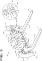
- FIGS. 1-6 illustrate various views of a pallet fork 100 according to an embodiment of the present disclosure.
- the pallet fork 100 includes a frame 102.
- the frame 102 may take many different forms as will be recognized by those of ordinary skill in this art.
- the frame 102 includes a top support tube 104 and a bottom support tube 106.
- the top support tube 104 and the bottom support tube 106 may form individual structural members of the pallet fork 100 and may be disposed approximately parallel to one another.
- top support tube 104 has a square cross sectional shape and bottom support tube 106 has a rectangular cross sectional shape.
- support tubes 104 and 106 may have other cross-sectional shapes.
- the components of the pallet fork 100 are generally formed of iron, steel or other material, which may be hardened, annealed, or otherwise heat-treated.
- the top support tube 104 and bottom support tube 106 may be secured together by sets of ribs, such as a set of inner ribs 108 and a set of outer ribs 110.
- the inner ribs 108 are the vertically oriented plates near a center point or a midplane of the top support tube 104 and the bottom support tube 106.
- the inner ribs 108 are structurally joined to the top support tube 104 and the bottom support tube 106 by welding, brazing, or any other practical means.
- the inner ribs 108 are oriented with an outward slant towards a rear portion of the of pallet fork 100 such that a user operating a machine (not shown) coupled to the pallet fork 100 can view from an operator's station on the machine through the inner ribs 108 substantially without visual obstruction from the inner ribs 108. In other words, the user would substantially only see rear edge portions of the inner ribs 108 when viewing from the operator's station (See also FIG. 4 ).
- the inner ribs 108 may be approximately parallel to one another, and approximately normal to the top support tube 104 and the bottom support tube 106 (e.g., substantially normal to a longitudinal direction L of the pallet fork 100).
- the inner ribs 108 are two separate plate-like members in the illustrated embodiment, however may be formed as a single plate or other element, or more than two plates, based on the design of the pallet fork 100.
- the outer ribs 110 are the vertically oriented plates close to the distal ends of the top support tube 104 and the bottom support tube 106.
- the outer ribs 110 are also structurally joined to the top support tube 104 and the bottom support tube 106 by welding, brazing, or any other practical means.
- the outer ribs 110 are oriented with an inward slant towards a rear portion of the of pallet fork 100 such that the user operating the machine coupled to the pallet fork 100 can view from an operator's station on the machine through the outer ribs 110 substantially without visual obstruction from the outer ribs 110. In other words, the user would substantially only see rear edge portions of the outer ribs 110 when viewing from the operator's station (See also FIG 4 ).
- the outer ribs 110 may be approximately parallel to one another.
- the outer ribs 110 may also be approximately normal to the top support tube 104 and the bottom support tube 106.
- the outer ribs 110 are two separate plate-like members in the illustrated embodiment, however may be formed as more than two individual plates or other elements, based on the design of the pallet fork 100.
- the distal ends of the top support tube 104 and the bottom support tube 106 are joined by a pair of end plates 112.
- the end plates 112 may be structurally joined to the top support tube 104 and the bottom support tube 106 by welding, brazing, riveting, or any other practical means.
- the end plates 112 may be vertically oriented plate-like members, and may be approximately parallel to one another and approximately normal to the top support tube 104 and the bottom support tube 106.
- the frame 102 supports a fork bar 114 and a carriage plate 116.
- the fork bar 114 and the carriage plate 116 may extend in the longitudinal direction L of the pallet fork 100 and be supported by the end plates 112, the inner ribs 108, and the outer ribs 110.
- the end plates 112 and the inner ribs 108 may include substantially parallel and aligned bores for supporting the fork bar 114.
- the fork bar 114 may be bolted, welded, or otherwise coupled to the end plates 112 to keep the fork bar 114 from retracting out of the bores.
- the fork bar 114 is formed of a solid steel bar having a circular cross-sectional shape.
- the pallet fork 100 may include a single fork bar 114 spanning between the end plates 112, or alternatively the fork bar 114 may be divided into two separate bars which may be joined, such as, at a laterally central location of the pallet fork 100. Dividing the fork bar 114 into two separate smaller bars facilitates assembling and disassembling as each bar will be shorter and weigh less.
- the carriage plate 116 may be structurally joined to the bottom support tube 106 by welding, brazing, bolts, screws, rivets, or any other practical means. In another embodiment, the carriage plate 116 may be formed integrally with the bottom support tube 106. However, in yet another embodiment, the carriage plate 116 may be provided anywhere between the top support tube 104 and the bottom support tube 106 and be supported by the end plates 112, the inner ribs 108, and the outer ribs 110.
- Fork tines 118 are mounted to the fork bar 114 via a tube 125.
- the fork tines 118 include a horizontal leg 120 and a vertical leg 122 which may be approximately normal to one another.
- a bore 124 is formed through tube 125.
- Tube 125 is attached to an upper portion of vertical leg 122 of each of the fork tines 118 by welding, brazing, riveting, or any other practical means.
- tube 125 extends substantially along a width of vertical leg 122.
- tube 125 may be integrally formed in vertical leg 122 of each fork tine 118.
- the bore 124 is substantially circular and configured to receive and mate with the fork bar 114.
- Each of the fork tines 118 may rotate about the fork bar 114 at the bore 124. Further, each of fork tines 118 may also have lateral movement along the fork bar 114 in the longitudinal direction L.
- a bracket 126 is attached to a rear portion of the vertical leg 122 of each of the fork tines 118.
- the bracket 126 is disposed in the proximity of the carriage plate 116 and joined to the vertical leg 122 of the fork tine 118 by welding, brazing, riveting or any other practical means.
- the bracket 126 has an opening 127, substantially normal to the longitudinal direction L, such that a lower locking member 128 may be selectively inserted in the opening 127 of the bracket 126.
- the lower locking member 128 may include a head portion 130 and a shaft portion 132.
- the shaft portion 132 of the lower locking member 128 is configured to be partially received in the opening 127 of the bracket 126 and partially adjoined to the carriage plate 116.
- the head portion 130 of the lower locking member 128 may have a through-hole 134, which is substantially aligned to a pair of apertures 136 provided on the bracket 126.
- a first pin 138 is configured to be selectively inserted in the through-hole 134 of the lower locking member 128, and the apertures 136 of the bracket 126, to hold the lower locking member 128 in the bracket 126.
- the first pin 138 may be a pull lock pin, such as a lynch pin, with a ring grip 140.
- the lower locking member 128 may have different shape, for example, but not limited to, a looped shape, a folded/clamp shape, or any other practical shape.
- the lower locking member 128 may use a bolt and nut assembly to hold the lower locking member 128 in the bracket 126.
- a locking plate 142 is provided on the top support tube 104 of the frame 102.
- the locking plate 142 may have one or more notches 144 used for locating fork tines 118 along longitudinal direction L of the pallet fork 100.
- an upper locking member 346 is configured to be selectively inserted through a slot 148 in tube 125 provided on the vertical leg 122 of the fork tine 118.
- the slot 148 is formed approximately one-half the distance through tube 125.
- the upper locking member 346 includes a head portion 350 and a shaft portion 352, thereby substantially forming a question mark ("?”) shape.
- the shaft portion 352 may include an aperture 354 through shaft portion 352.
- Upper locking member 346 is formed of iron, steel, or other suitable material.
- upper locking member 346 is formed of ASTM-572 steel by flame cutting a plate of the ASTM-572 steel. However, milling, casting, molding, extruding, or other forming process may form upper locking member 346.
- the shaft portion 352 of the upper locking member 346 may be selectively inserted through slot 148 and into one of a plurality of notches 144 of the locking plate 142. Inserting upper locking member 346 into different slots 148 allows the fork tines 118 to be located and held at different locations along fork bar 114.
- Upper locking member 346 and slot 148 may be formed so that shaft portion 352 can only enter slot 148 at one orientation, such as where the open point 351 of the head portion 350 rests on top support tube 104 when upper locking member 346 is inserted.
- shaft portion 352 and slot 148 may have a unique shape (e.g., mating wedge shape) or a specific dimension (e.g., larger dimension side to side than front to back or visa-versa).
- upper locking member 346 is inserted backwards (e.g., 180° from that shown in FIGs. 3 , 5, and 6 ), a rear shoulder 353 of head portion 350 will interfere with top support tube 104 and thus, upper locking member 346 cannot be fully inserted in slot 148 with such orientation.
- FIGs. 5 and 6 illustrate a sectional view of the pallet fork 100 along lines A-A of FIG. 4 where the fork tines 118 are lowered in FIG 5 and rotated upward about fork bar 114 in FIG 6 .
- open point 351 of head portion 350 of the upper locking member 346 may be configured to rest on the top support tube 104.
- a second pin 156 may be selectively inserted in the aperture 354 (see FIG. 3 ) of the upper locking member 346.
- the second pin 156 may be a pull lock pin, such as a lynch pin, selectively inserted in the aperture 354 to hold the upper locking member 346 in the notch 144 of the locking plate 142.
- the length of the slot 148 allows the fork tines 118 to rotate upward an angle 8 until the rear shoulder 353 of the head portion 350 contacts the tube 125 or the top of the vertical leg 122 of the fork tine 118.
- the fork tine 118 can rotate upward angle 8 a range of approximately 0° to approximately 75' from horizontal as shown in FIG. 6 .
- pivotable motion is restricted to a range of approximately 0° to approximately 75°. The upward motion is limited by the rear shoulder 353 portion of the upper locking member 346 contacting an end of the slot 148 in the slotted tube 125.
- adjusting a depth of the slot 148 or adjusting the size/shape of the shoulder portion 353 adjusts the travel range of angle ⁇ .
- the pallet fork 100 may include a retainer 158 to store the lower locking member 128 and/or the upper locking member 346, when not in use.
- the retainer 158 may be mounted on the pair of end plates 112 by welding, brazing, riveting, or any other practical means.
- the pallet fork 100 may include upper mounting brackets 160 and lower mounting brackets 162 for removably coupling the pallet fork 100 with lift arms on a machine, such as a wheel loader or other machine (not shown).
- the upper mounting brackets 160 may be welded, brazed, bolted, riveted, or otherwise attached to top support tube 104.
- the lower mounting brackets 162 may be welded, brazed, bolted, riveted, or otherwise attached to bottom support tube 106.
- the lift arms of the machine include a coupling system with pins, wedges, locks, and various other features that engage and lock with the upper mounting brackets 160 and the lower mounting brackets 162.
- the pallet fork 100 may be used while coupled to a wheel loader, a track loader, a tractor, a forklift, or any other machine.
- the fork tines 118 can be fixed, or be allowed to swing about the fork bar 114 when the pallet fork 100 tilts forward.
- the fork tines 118 can be laterally moved along the fork bar 114 for customizing according to palletized loads.
- the lower and the upper locking members 128 and 346 may be selectively used to restrict the swingable and the lateral motion of the fork tines 118, respectively.
- the disclosure provides a quick and retrofittable system of restricting the swingable motion of the fork tine 118 relative to the frame 102 of the pallet fork 100.
- the fork tine 118 may be mounted to the fork bar 114.
- the bore 124 provided on the vertical leg 122 of the fork tine 118 may receive the fork bar 114.
- the vertical leg 122 of the fork tine 118 may be aligned with the carriage plate 116, which is connected to the bottom support tube 106 of the frame 102 of the pallet fork 100.
- the alignment may be achieved by moving the fork tine 118 to bring the vertical leg 122 of the fork tine 118 in contact with the bottom support tube 106 of the frame 102.
- the lower locking member 128 may be selectively inserted in the bracket 126 provided on the vertical leg 122 of the fork tine 118, to engage the fork tine 118 with the carriage plate 116 of the frame 102.
- the swingable motion of the fork tine 118 relative to the fork bar 114 supported on the frame 102 may be restricted by lower locking member 128.
- the lower locking member 128 described above is a locking device including the head portion 130 and the shaft portion 132. Moreover, the lower locking member 128 may be fixed or removed from the bracket 126 without any tools. Additionally, the lower locking member 128 may not hamper visibility of an operator through the frame 102 to the ends of the fork tines 118 and also to the load to be picked-up. In an embodiment, as illustrated in FIG. 5 , the top support tube 104 may be angled with respect to the bottom support tube 106 to further improve the visibility of the operator.
- the "?” shaped upper locking member 346 may be inserted in the notch 144 of the locking plate 142 supported on the frame 102, as described above.
- the upper locking member 346 may assist in restricting the lateral motion of the fork tine 118 relative to the fork bar 114.
- the upper locking member 346 may be held in the notch 144 by selectively inserting the second pin 156 in the upper locking member 346.
- the lower locking member 128 and/or the upper locking member 346 may be stored in the retainer 158 when not in use.
- the carriage plate 116, the bracket 126, and the locking plate 142 are retrofittable to an existing pallet fork by a cost effective method including welding, brazing or riveting, or any other practical means.
- the present disclosure provides a pallet fork having tines that can be locked in a lateral position on the fork carriage assembly.
- the carriage assembly has a fixed slotted plate.
- One or more locking members capture the fork tine using the fixed slotted plate and thereby prevents lateral/horizontal movement of the fork tines.
- embodiments described herein still allow the fork tines to swing freely about the fork bar an angle ⁇ .
- the present disclosure provides a simple locking device for tine lateral movement, which do not require tools for adjustment. This also provides optimized visibility for an operator the locking plates are not in sight lines for an operator viewing the tines from an operator station.
Landscapes
- Engineering & Computer Science (AREA)
- Transportation (AREA)
- Structural Engineering (AREA)
- Civil Engineering (AREA)
- Life Sciences & Earth Sciences (AREA)
- Geology (AREA)
- Mechanical Engineering (AREA)
- Pallets (AREA)
Claims (10)
- Palettengabel (100) mit:einem Rahmen (102), der ein oberes Stützrohr (104) und ein unteres Stützrohr (106) zwischen zwei gegenüberliegenden Endplatten (112) aufweist;einer Gabelstange (114) und einer Trägerplatte (116), die von dem Rahmen (102) gehalten wird und sich in Längsrichtung (L) der Palettengabel (100) erstreckt;einer Gabelzinke (118), die über ein geschlitztes Rohr (125) mit der Gabelstange (114) verbunden ist, wobei die Gabelzinke (118) eine Drehbewegung und eine Längsbewegung relativ zur Drehbewegung sowie einen vertikalen Schenkel (122) und einen horizontalen Schenkel (120) aufweist und das geschlitzte Rohr (125) an einem oberen Abschnitt des vertikalen Schenkels (122) angeordnet ist;einer Verriegelungsplatte (142), die an dem oberen Stützrohr (104) mehrere Aussparungen (144) aufweist;ferner gekennzeichnet durchein oberes Verriegelungselement (346), das dazu ausgebildet ist, durch einen Schlitz (148) des geschlitzten Rohres (125) und durch eine der Aussparungen (144) wahlweise eingeführt zu werden zum Eingreifen des vertikalen Schenkels (122) der Gabelzinke (118) in die Verriegelungsplatte (142), um die Längsbewegung der Gabelzinke (118) einzuschränken, wobei das obere Verriegelungselement (346) einen Kopfabschnitt (130, 350) mit einem offenen Ende (351) aufweist, das auf einer oberen Fläche des oberen Stützrohres (104) aufliegt.
- Palettengabel (100) nach Anspruch 1, wobei das obere Verriegelungselement (346) in Form eines Fragezeichens ausgebildet ist.
- Palettengabel (100) nach Anspruch 1, wobei das obere Verriegelungselement (346) einen Schaftabschnitt (132, 352) aufweist, der dazu ausgebildet ist, den Schlitz (148) in dem geschlitzten Rohr (125) mit einer einzigen Orientierung zu passieren.
- Palettengabel (100) nach Anspruch 1, wobei die Drehbewegung in einem Bereich zwischen ungefähr 0° und ungefähr 75° eingeschränkt wird, indem ein hinterer Schulterabschnitt (353) des oberen Verriegelungselementes (346) ein Ende des Schlitzes (148) in dem geschlitzten Rohr (125) berührt.
- Palettengabel (100) nach Anspruch 1, wobei sich der Schlitz (148) im geschlitzten Rohr (125) ungefähr zur Hälfte durch das geschlitzte Rohr (125) erstreckt.
- Palettengabel (100) nach Anspruch 1, ferner mit einem Verriegelungsstift, der zum wahlweisen Einsetzen in dem oberen Verriegelungselement (346) ausgebildet ist, um das obere Verriegelungselement (346) in einer der Aussparungen (144) zu fixieren.
- Palettengabel (100) nach Anspruch 1, ferner mit einem ersten Satz von Rippen, der sich zwischen dem oberen Stützrohr (104) und dem unteren Stützrohr (106) erstreckt und mit einer nach innen gerichteten Neigung zu einem Hinterabschnitt der Palettengabel (100) orientiert ist.
- Palettengabel (100) nach Anspruch 7, ferner mit einem zweiten Satz von Rippen, der sich zwischen dem oberen Stützrohr (104) und dem unteren Stützrohr (106) erstreckt und mit einer nach außen gerichteten Neigung zum Hinterabschnitt der Palettengabel (100) orientiert ist.
- Palettengabel (100) nach Anspruch 1, ferner mit einem Bügel (126), die an dem vertikalen Schenkel (122) der Gabelzinke (118) angebracht ist, und einem unteren Verriegelungselement (128), das zum wahlweisen Einsetzen in dem Bügel (126) ausgebildet ist, um die Gabelzinke (118) in Eingriff mit der Trägerplatte (116) zu bringen und die Drehbewegung der Gabelzinke (118) einzuschränken.
- Palettengabel (100) nach Anspruch 7, ferner mit einem zweiten Verriegelungsstift, der zum wahlweisen Einsetzen in dem unteren Verriegelungselement (128) ausgebildet ist, um das untere Verriegelungselement (128) in dem Bügel (126) zu fixieren.
Applications Claiming Priority (2)
| Application Number | Priority Date | Filing Date | Title |
|---|---|---|---|
| US13/274,672 US8944218B2 (en) | 2011-10-17 | 2011-10-17 | Pallet fork |
| PCT/US2012/059629 WO2013059054A1 (en) | 2011-10-17 | 2012-10-11 | Pallet fork |
Publications (3)
| Publication Number | Publication Date |
|---|---|
| EP2768760A1 EP2768760A1 (de) | 2014-08-27 |
| EP2768760A4 EP2768760A4 (de) | 2015-04-08 |
| EP2768760B1 true EP2768760B1 (de) | 2016-04-13 |
Family
ID=48085238
Family Applications (1)
| Application Number | Title | Priority Date | Filing Date |
|---|---|---|---|
| EP12842258.1A Not-in-force EP2768760B1 (de) | 2011-10-17 | 2012-10-11 | Palettengabel |
Country Status (6)
| Country | Link |
|---|---|
| US (1) | US8944218B2 (de) |
| EP (1) | EP2768760B1 (de) |
| CN (1) | CN204138302U (de) |
| BR (1) | BR112014009450A2 (de) |
| CA (1) | CA2851791A1 (de) |
| WO (1) | WO2013059054A1 (de) |
Families Citing this family (7)
| Publication number | Priority date | Publication date | Assignee | Title |
|---|---|---|---|---|
| US20150251885A1 (en) * | 2014-03-07 | 2015-09-10 | Signs365 | Variable fork attachment for hi-lo vehicle |
| US10501297B2 (en) * | 2015-07-20 | 2019-12-10 | Digga Australia Pty Ltd | Lockable floating forklift tine system |
| CN105060180A (zh) * | 2015-09-14 | 2015-11-18 | 安庆联动属具股份有限公司 | 一种用于叉车的两用叉夹 |
| CN105347259B (zh) * | 2015-11-18 | 2017-08-25 | 广西柳工机械股份有限公司 | 穿轴式货叉工作装置 |
| CN106395692A (zh) * | 2016-06-28 | 2017-02-15 | 徐工集团工程机械股份有限公司科技分公司 | 一种工程机械用货叉总成 |
| CN106395691A (zh) * | 2016-06-28 | 2017-02-15 | 徐工集团工程机械股份有限公司科技分公司 | 一种工程机械用货叉托架总成 |
| IT201900000607A1 (it) * | 2019-01-15 | 2020-07-15 | Manitou Italia Srl | Attrezzatura perfezionata. |
Family Cites Families (17)
| Publication number | Priority date | Publication date | Assignee | Title |
|---|---|---|---|---|
| US3734327A (en) * | 1971-04-05 | 1973-05-22 | W Ellis | Lift truck side shifting means |
| US3851779A (en) * | 1972-02-14 | 1974-12-03 | Towmotor Corp | Lift truck fork retaining pins |
| US4498838A (en) * | 1983-04-04 | 1985-02-12 | Towmotor Corporation | Retention device for a load engaging member |
| KR860001967B1 (ko) | 1984-02-06 | 1986-11-07 | 유성기업 주식회사 | 피스톤링의 산화철 소결방법 |
| US4850789A (en) | 1987-11-16 | 1989-07-25 | Zimmerman Emil F | Interfacing lift hitch |
| US4963071A (en) | 1989-06-23 | 1990-10-16 | American Coupler Systems, Inc. | Coupler assembly between a prime mover and a work implement |
| JP3065434B2 (ja) | 1992-06-25 | 2000-07-17 | 株式会社豊田自動織機製作所 | フォークアタッチメントのフォーク固定装置 |
| JP3039728B2 (ja) | 1992-08-05 | 2000-05-08 | 株式会社豊田自動織機製作所 | 全回転フォークアタッチメントのフォーク固定装置 |
| US5314292A (en) | 1992-09-29 | 1994-05-24 | Holopainen Vaino J | Material clamping apparatus |
| DE69704589T2 (de) * | 1996-06-25 | 2001-08-09 | J.C. Bamford Excavators Ltd., Uttoxeter | Handhabungsfahrzeug für Material |
| US5639205A (en) | 1996-08-23 | 1997-06-17 | Deere & Company | Parkable grapple having quick attachment to loader holder |
| US6168369B1 (en) | 1998-10-29 | 2001-01-02 | Caterpillar Inc. | Carrier retainer system |
| US6672823B2 (en) * | 2001-09-11 | 2004-01-06 | Cascade Corporation | Fork positioner for facilitating replacement of forks on lift trucks |
| US6990838B2 (en) | 2002-03-11 | 2006-01-31 | Bryan Witchey | Skid steer attachment lock |
| FR2869054B1 (fr) | 2004-04-14 | 2006-07-07 | Etude Et D Innovation Dans Le | Dispositif de verrouillage d'un outil sur le cadre porte-outil d'un chargeur, notamment a usage agricole. |
| US9309098B2 (en) * | 2008-10-24 | 2016-04-12 | Caterpillar Inc. | Pallet fork with improved visibility and versatility |
| JP5527967B2 (ja) | 2008-12-26 | 2014-06-25 | ユニキャリア株式会社 | フォーク固定装置 |
-
2011
- 2011-10-17 US US13/274,672 patent/US8944218B2/en active Active
-
2012
- 2012-10-11 EP EP12842258.1A patent/EP2768760B1/de not_active Not-in-force
- 2012-10-11 BR BR112014009450A patent/BR112014009450A2/pt not_active IP Right Cessation
- 2012-10-11 CN CN201290000878.XU patent/CN204138302U/zh not_active Expired - Fee Related
- 2012-10-11 WO PCT/US2012/059629 patent/WO2013059054A1/en not_active Ceased
- 2012-10-11 CA CA2851791A patent/CA2851791A1/en not_active Abandoned
Also Published As
| Publication number | Publication date |
|---|---|
| EP2768760A1 (de) | 2014-08-27 |
| BR112014009450A2 (pt) | 2017-04-25 |
| WO2013059054A1 (en) | 2013-04-25 |
| US8944218B2 (en) | 2015-02-03 |
| EP2768760A4 (de) | 2015-04-08 |
| CA2851791A1 (en) | 2013-04-25 |
| US20130092478A1 (en) | 2013-04-18 |
| CN204138302U (zh) | 2015-02-04 |
Similar Documents
| Publication | Publication Date | Title |
|---|---|---|
| EP2768760B1 (de) | Palettengabel | |
| US8899906B2 (en) | Locking members for pallet fork | |
| US20100101895A1 (en) | Pallet fork with improved visibility and versatility | |
| US8454295B2 (en) | Detachable boom apparatus for fork trucks | |
| EP1918134B1 (de) | Reißnagelanhängungen | |
| EP3296470B1 (de) | Austauschbarer arbeitsteil für ein abbruchwerkzeug | |
| EP2999621B1 (de) | Ersatzrad-kupplungsanordnung mit direkt montierten halteklammern | |
| EP3683184B1 (de) | Vorrichtung für selbstangetriebene arbeitsmaschine | |
| EP2647275A2 (de) | Verbindungsvorrichtung für einen traktor | |
| EP2441651A2 (de) | Traktorgewichtsanordnung | |
| DE102013002622A1 (de) | Vorrichtung und Verfahren zum autonomen Kuppeln eines Werkzeugs an ein Arbeitsfahrzeug | |
| WO2014056904A1 (en) | Subframe system | |
| EP3988497B1 (de) | Verbesserter gabelträger | |
| CA3103518C (en) | Quick connect system for industrial and construction equipment | |
| EP2989882A1 (de) | Schrägfördereranordnung zur montage eines vorsatzes an einen mähdrescher | |
| CN116710388A (zh) | 用于工业车辆的工作辅助系统 | |
| EP4344522B1 (de) | Anhängerkupplung für ein fahrzeug | |
| KR101074289B1 (ko) | 이동 작업차용 로더에 설치되는 어태치먼트 장착장치 | |
| EP2662500A1 (de) | Verriegelbare Verlängerung für Arbeitswerkzeug | |
| KR200186868Y1 (ko) | 텔레스코픽 핸들러의 작업장치 | |
| US7258376B2 (en) | Lifting aid for planar members | |
| US20020092708A1 (en) | Quick coupler system | |
| US20040083867A1 (en) | Method and apparatus for detachably securing tool attachments to a cultivator | |
| US20080050183A1 (en) | Slide rail panel pushing assembly | |
| CA2502259C (en) | Lifting aid for planar members |
Legal Events
| Date | Code | Title | Description |
|---|---|---|---|
| PUAI | Public reference made under article 153(3) epc to a published international application that has entered the european phase |
Free format text: ORIGINAL CODE: 0009012 |
|
| 17P | Request for examination filed |
Effective date: 20140328 |
|
| AK | Designated contracting states |
Kind code of ref document: A1 Designated state(s): AL AT BE BG CH CY CZ DE DK EE ES FI FR GB GR HR HU IE IS IT LI LT LU LV MC MK MT NL NO PL PT RO RS SE SI SK SM TR |
|
| DAX | Request for extension of the european patent (deleted) | ||
| RA4 | Supplementary search report drawn up and despatched (corrected) |
Effective date: 20150311 |
|
| RIC1 | Information provided on ipc code assigned before grant |
Ipc: B66F 9/14 20060101AFI20150305BHEP Ipc: B66F 9/12 20060101ALI20150305BHEP |
|
| GRAP | Despatch of communication of intention to grant a patent |
Free format text: ORIGINAL CODE: EPIDOSNIGR1 |
|
| INTG | Intention to grant announced |
Effective date: 20151015 |
|
| GRAS | Grant fee paid |
Free format text: ORIGINAL CODE: EPIDOSNIGR3 |
|
| GRAA | (expected) grant |
Free format text: ORIGINAL CODE: 0009210 |
|
| AK | Designated contracting states |
Kind code of ref document: B1 Designated state(s): AL AT BE BG CH CY CZ DE DK EE ES FI FR GB GR HR HU IE IS IT LI LT LU LV MC MK MT NL NO PL PT RO RS SE SI SK SM TR |
|
| REG | Reference to a national code |
Ref country code: GB Ref legal event code: FG4D |
|
| REG | Reference to a national code |
Ref country code: AT Ref legal event code: REF Ref document number: 789912 Country of ref document: AT Kind code of ref document: T Effective date: 20160415 Ref country code: CH Ref legal event code: EP |
|
| REG | Reference to a national code |
Ref country code: IE Ref legal event code: FG4D |
|
| REG | Reference to a national code |
Ref country code: DE Ref legal event code: R096 Ref document number: 602012017193 Country of ref document: DE |
|
| REG | Reference to a national code |
Ref country code: LT Ref legal event code: MG4D |
|
| REG | Reference to a national code |
Ref country code: AT Ref legal event code: MK05 Ref document number: 789912 Country of ref document: AT Kind code of ref document: T Effective date: 20160413 |
|
| REG | Reference to a national code |
Ref country code: NL Ref legal event code: MP Effective date: 20160413 |
|
| PG25 | Lapsed in a contracting state [announced via postgrant information from national office to epo] |
Ref country code: NO Free format text: LAPSE BECAUSE OF FAILURE TO SUBMIT A TRANSLATION OF THE DESCRIPTION OR TO PAY THE FEE WITHIN THE PRESCRIBED TIME-LIMIT Effective date: 20160713 Ref country code: LT Free format text: LAPSE BECAUSE OF FAILURE TO SUBMIT A TRANSLATION OF THE DESCRIPTION OR TO PAY THE FEE WITHIN THE PRESCRIBED TIME-LIMIT Effective date: 20160413 Ref country code: FI Free format text: LAPSE BECAUSE OF FAILURE TO SUBMIT A TRANSLATION OF THE DESCRIPTION OR TO PAY THE FEE WITHIN THE PRESCRIBED TIME-LIMIT Effective date: 20160413 Ref country code: PL Free format text: LAPSE BECAUSE OF FAILURE TO SUBMIT A TRANSLATION OF THE DESCRIPTION OR TO PAY THE FEE WITHIN THE PRESCRIBED TIME-LIMIT Effective date: 20160413 Ref country code: NL Free format text: LAPSE BECAUSE OF FAILURE TO SUBMIT A TRANSLATION OF THE DESCRIPTION OR TO PAY THE FEE WITHIN THE PRESCRIBED TIME-LIMIT Effective date: 20160413 |
|
| PGFP | Annual fee paid to national office [announced via postgrant information from national office to epo] |
Ref country code: GB Payment date: 20160926 Year of fee payment: 5 |
|
| PG25 | Lapsed in a contracting state [announced via postgrant information from national office to epo] |
Ref country code: ES Free format text: LAPSE BECAUSE OF FAILURE TO SUBMIT A TRANSLATION OF THE DESCRIPTION OR TO PAY THE FEE WITHIN THE PRESCRIBED TIME-LIMIT Effective date: 20160413 Ref country code: RS Free format text: LAPSE BECAUSE OF FAILURE TO SUBMIT A TRANSLATION OF THE DESCRIPTION OR TO PAY THE FEE WITHIN THE PRESCRIBED TIME-LIMIT Effective date: 20160413 Ref country code: AT Free format text: LAPSE BECAUSE OF FAILURE TO SUBMIT A TRANSLATION OF THE DESCRIPTION OR TO PAY THE FEE WITHIN THE PRESCRIBED TIME-LIMIT Effective date: 20160413 Ref country code: PT Free format text: LAPSE BECAUSE OF FAILURE TO SUBMIT A TRANSLATION OF THE DESCRIPTION OR TO PAY THE FEE WITHIN THE PRESCRIBED TIME-LIMIT Effective date: 20160816 Ref country code: SE Free format text: LAPSE BECAUSE OF FAILURE TO SUBMIT A TRANSLATION OF THE DESCRIPTION OR TO PAY THE FEE WITHIN THE PRESCRIBED TIME-LIMIT Effective date: 20160413 Ref country code: GR Free format text: LAPSE BECAUSE OF FAILURE TO SUBMIT A TRANSLATION OF THE DESCRIPTION OR TO PAY THE FEE WITHIN THE PRESCRIBED TIME-LIMIT Effective date: 20160714 Ref country code: LV Free format text: LAPSE BECAUSE OF FAILURE TO SUBMIT A TRANSLATION OF THE DESCRIPTION OR TO PAY THE FEE WITHIN THE PRESCRIBED TIME-LIMIT Effective date: 20160413 Ref country code: HR Free format text: LAPSE BECAUSE OF FAILURE TO SUBMIT A TRANSLATION OF THE DESCRIPTION OR TO PAY THE FEE WITHIN THE PRESCRIBED TIME-LIMIT Effective date: 20160413 |
|
| PG25 | Lapsed in a contracting state [announced via postgrant information from national office to epo] |
Ref country code: BE Free format text: LAPSE BECAUSE OF FAILURE TO SUBMIT A TRANSLATION OF THE DESCRIPTION OR TO PAY THE FEE WITHIN THE PRESCRIBED TIME-LIMIT Effective date: 20160413 Ref country code: IT Free format text: LAPSE BECAUSE OF FAILURE TO SUBMIT A TRANSLATION OF THE DESCRIPTION OR TO PAY THE FEE WITHIN THE PRESCRIBED TIME-LIMIT Effective date: 20160413 |
|
| REG | Reference to a national code |
Ref country code: DE Ref legal event code: R097 Ref document number: 602012017193 Country of ref document: DE |
|
| PG25 | Lapsed in a contracting state [announced via postgrant information from national office to epo] |
Ref country code: RO Free format text: LAPSE BECAUSE OF FAILURE TO SUBMIT A TRANSLATION OF THE DESCRIPTION OR TO PAY THE FEE WITHIN THE PRESCRIBED TIME-LIMIT Effective date: 20160413 Ref country code: CZ Free format text: LAPSE BECAUSE OF FAILURE TO SUBMIT A TRANSLATION OF THE DESCRIPTION OR TO PAY THE FEE WITHIN THE PRESCRIBED TIME-LIMIT Effective date: 20160413 Ref country code: EE Free format text: LAPSE BECAUSE OF FAILURE TO SUBMIT A TRANSLATION OF THE DESCRIPTION OR TO PAY THE FEE WITHIN THE PRESCRIBED TIME-LIMIT Effective date: 20160413 Ref country code: DK Free format text: LAPSE BECAUSE OF FAILURE TO SUBMIT A TRANSLATION OF THE DESCRIPTION OR TO PAY THE FEE WITHIN THE PRESCRIBED TIME-LIMIT Effective date: 20160413 Ref country code: SK Free format text: LAPSE BECAUSE OF FAILURE TO SUBMIT A TRANSLATION OF THE DESCRIPTION OR TO PAY THE FEE WITHIN THE PRESCRIBED TIME-LIMIT Effective date: 20160413 |
|
| PGFP | Annual fee paid to national office [announced via postgrant information from national office to epo] |
Ref country code: DE Payment date: 20161031 Year of fee payment: 5 |
|
| PLBE | No opposition filed within time limit |
Free format text: ORIGINAL CODE: 0009261 |
|
| STAA | Information on the status of an ep patent application or granted ep patent |
Free format text: STATUS: NO OPPOSITION FILED WITHIN TIME LIMIT |
|
| PG25 | Lapsed in a contracting state [announced via postgrant information from national office to epo] |
Ref country code: SM Free format text: LAPSE BECAUSE OF FAILURE TO SUBMIT A TRANSLATION OF THE DESCRIPTION OR TO PAY THE FEE WITHIN THE PRESCRIBED TIME-LIMIT Effective date: 20160413 |
|
| 26N | No opposition filed |
Effective date: 20170116 |
|
| PG25 | Lapsed in a contracting state [announced via postgrant information from national office to epo] |
Ref country code: SI Free format text: LAPSE BECAUSE OF FAILURE TO SUBMIT A TRANSLATION OF THE DESCRIPTION OR TO PAY THE FEE WITHIN THE PRESCRIBED TIME-LIMIT Effective date: 20160413 |
|
| REG | Reference to a national code |
Ref country code: CH Ref legal event code: PL |
|
| REG | Reference to a national code |
Ref country code: IE Ref legal event code: MM4A |
|
| REG | Reference to a national code |
Ref country code: FR Ref legal event code: ST Effective date: 20170630 |
|
| PG25 | Lapsed in a contracting state [announced via postgrant information from national office to epo] |
Ref country code: FR Free format text: LAPSE BECAUSE OF NON-PAYMENT OF DUE FEES Effective date: 20161102 Ref country code: CH Free format text: LAPSE BECAUSE OF NON-PAYMENT OF DUE FEES Effective date: 20161031 Ref country code: LI Free format text: LAPSE BECAUSE OF NON-PAYMENT OF DUE FEES Effective date: 20161031 |
|
| PG25 | Lapsed in a contracting state [announced via postgrant information from national office to epo] |
Ref country code: LU Free format text: LAPSE BECAUSE OF NON-PAYMENT OF DUE FEES Effective date: 20161011 |
|
| PG25 | Lapsed in a contracting state [announced via postgrant information from national office to epo] |
Ref country code: IE Free format text: LAPSE BECAUSE OF NON-PAYMENT OF DUE FEES Effective date: 20161011 |
|
| REG | Reference to a national code |
Ref country code: DE Ref legal event code: R119 Ref document number: 602012017193 Country of ref document: DE |
|
| PG25 | Lapsed in a contracting state [announced via postgrant information from national office to epo] |
Ref country code: HU Free format text: LAPSE BECAUSE OF FAILURE TO SUBMIT A TRANSLATION OF THE DESCRIPTION OR TO PAY THE FEE WITHIN THE PRESCRIBED TIME-LIMIT; INVALID AB INITIO Effective date: 20121011 |
|
| GBPC | Gb: european patent ceased through non-payment of renewal fee |
Effective date: 20171011 |
|
| PG25 | Lapsed in a contracting state [announced via postgrant information from national office to epo] |
Ref country code: MK Free format text: LAPSE BECAUSE OF FAILURE TO SUBMIT A TRANSLATION OF THE DESCRIPTION OR TO PAY THE FEE WITHIN THE PRESCRIBED TIME-LIMIT Effective date: 20160413 Ref country code: MT Free format text: LAPSE BECAUSE OF NON-PAYMENT OF DUE FEES Effective date: 20161031 Ref country code: CY Free format text: LAPSE BECAUSE OF FAILURE TO SUBMIT A TRANSLATION OF THE DESCRIPTION OR TO PAY THE FEE WITHIN THE PRESCRIBED TIME-LIMIT Effective date: 20160413 Ref country code: MC Free format text: LAPSE BECAUSE OF FAILURE TO SUBMIT A TRANSLATION OF THE DESCRIPTION OR TO PAY THE FEE WITHIN THE PRESCRIBED TIME-LIMIT Effective date: 20160413 Ref country code: IS Free format text: LAPSE BECAUSE OF FAILURE TO SUBMIT A TRANSLATION OF THE DESCRIPTION OR TO PAY THE FEE WITHIN THE PRESCRIBED TIME-LIMIT Effective date: 20160413 |
|
| PG25 | Lapsed in a contracting state [announced via postgrant information from national office to epo] |
Ref country code: BG Free format text: LAPSE BECAUSE OF FAILURE TO SUBMIT A TRANSLATION OF THE DESCRIPTION OR TO PAY THE FEE WITHIN THE PRESCRIBED TIME-LIMIT Effective date: 20160413 Ref country code: DE Free format text: LAPSE BECAUSE OF NON-PAYMENT OF DUE FEES Effective date: 20180501 Ref country code: GB Free format text: LAPSE BECAUSE OF NON-PAYMENT OF DUE FEES Effective date: 20171011 |
|
| PG25 | Lapsed in a contracting state [announced via postgrant information from national office to epo] |
Ref country code: TR Free format text: LAPSE BECAUSE OF FAILURE TO SUBMIT A TRANSLATION OF THE DESCRIPTION OR TO PAY THE FEE WITHIN THE PRESCRIBED TIME-LIMIT Effective date: 20160413 Ref country code: AL Free format text: LAPSE BECAUSE OF FAILURE TO SUBMIT A TRANSLATION OF THE DESCRIPTION OR TO PAY THE FEE WITHIN THE PRESCRIBED TIME-LIMIT Effective date: 20160413 |