EP2769426B1 - Vorrichtung zur spannungsversorgung - Google Patents
Vorrichtung zur spannungsversorgung Download PDFInfo
- Publication number
- EP2769426B1 EP2769426B1 EP12770028.4A EP12770028A EP2769426B1 EP 2769426 B1 EP2769426 B1 EP 2769426B1 EP 12770028 A EP12770028 A EP 12770028A EP 2769426 B1 EP2769426 B1 EP 2769426B1
- Authority
- EP
- European Patent Office
- Prior art keywords
- coolant
- plate
- cooling
- duct
- refrigerant
- Prior art date
- Legal status (The legal status is an assumption and is not a legal conclusion. Google has not performed a legal analysis and makes no representation as to the accuracy of the status listed.)
- Active
Links
Images


Classifications
-
- H—ELECTRICITY
- H01—ELECTRIC ELEMENTS
- H01M—PROCESSES OR MEANS, e.g. BATTERIES, FOR THE DIRECT CONVERSION OF CHEMICAL ENERGY INTO ELECTRICAL ENERGY
- H01M10/00—Secondary cells; Manufacture thereof
- H01M10/60—Heating or cooling; Temperature control
- H01M10/61—Types of temperature control
- H01M10/615—Heating or keeping warm
-
- B—PERFORMING OPERATIONS; TRANSPORTING
- B60—VEHICLES IN GENERAL
- B60L—PROPULSION OF ELECTRICALLY-PROPELLED VEHICLES; SUPPLYING ELECTRIC POWER FOR AUXILIARY EQUIPMENT OF ELECTRICALLY-PROPELLED VEHICLES; ELECTRODYNAMIC BRAKE SYSTEMS FOR VEHICLES IN GENERAL; MAGNETIC SUSPENSION OR LEVITATION FOR VEHICLES; MONITORING OPERATING VARIABLES OF ELECTRICALLY-PROPELLED VEHICLES; ELECTRIC SAFETY DEVICES FOR ELECTRICALLY-PROPELLED VEHICLES
- B60L50/00—Electric propulsion with power supplied within the vehicle
- B60L50/50—Electric propulsion with power supplied within the vehicle using propulsion power supplied by batteries or fuel cells
- B60L50/60—Electric propulsion with power supplied within the vehicle using propulsion power supplied by batteries or fuel cells using power supplied by batteries
- B60L50/64—Constructional details of batteries specially adapted for electric vehicles
-
- H—ELECTRICITY
- H01—ELECTRIC ELEMENTS
- H01M—PROCESSES OR MEANS, e.g. BATTERIES, FOR THE DIRECT CONVERSION OF CHEMICAL ENERGY INTO ELECTRICAL ENERGY
- H01M10/00—Secondary cells; Manufacture thereof
- H01M10/04—Construction or manufacture in general
- H01M10/0413—Large-sized flat cells or batteries for motive or stationary systems with plate-like electrodes
-
- H—ELECTRICITY
- H01—ELECTRIC ELEMENTS
- H01M—PROCESSES OR MEANS, e.g. BATTERIES, FOR THE DIRECT CONVERSION OF CHEMICAL ENERGY INTO ELECTRICAL ENERGY
- H01M10/00—Secondary cells; Manufacture thereof
- H01M10/04—Construction or manufacture in general
- H01M10/0481—Compression means other than compression means for stacks of electrodes and separators
-
- H—ELECTRICITY
- H01—ELECTRIC ELEMENTS
- H01M—PROCESSES OR MEANS, e.g. BATTERIES, FOR THE DIRECT CONVERSION OF CHEMICAL ENERGY INTO ELECTRICAL ENERGY
- H01M10/00—Secondary cells; Manufacture thereof
- H01M10/42—Methods or arrangements for servicing or maintenance of secondary cells or secondary half-cells
- H01M10/4207—Methods or arrangements for servicing or maintenance of secondary cells or secondary half-cells for several batteries or cells simultaneously or sequentially
-
- H—ELECTRICITY
- H01—ELECTRIC ELEMENTS
- H01M—PROCESSES OR MEANS, e.g. BATTERIES, FOR THE DIRECT CONVERSION OF CHEMICAL ENERGY INTO ELECTRICAL ENERGY
- H01M10/00—Secondary cells; Manufacture thereof
- H01M10/60—Heating or cooling; Temperature control
- H01M10/61—Types of temperature control
- H01M10/613—Cooling or keeping cold
-
- H—ELECTRICITY
- H01—ELECTRIC ELEMENTS
- H01M—PROCESSES OR MEANS, e.g. BATTERIES, FOR THE DIRECT CONVERSION OF CHEMICAL ENERGY INTO ELECTRICAL ENERGY
- H01M10/00—Secondary cells; Manufacture thereof
- H01M10/60—Heating or cooling; Temperature control
- H01M10/62—Heating or cooling; Temperature control specially adapted for specific applications
- H01M10/625—Vehicles
-
- H—ELECTRICITY
- H01—ELECTRIC ELEMENTS
- H01M—PROCESSES OR MEANS, e.g. BATTERIES, FOR THE DIRECT CONVERSION OF CHEMICAL ENERGY INTO ELECTRICAL ENERGY
- H01M10/00—Secondary cells; Manufacture thereof
- H01M10/60—Heating or cooling; Temperature control
- H01M10/65—Means for temperature control structurally associated with the cells
- H01M10/655—Solid structures for heat exchange or heat conduction
- H01M10/6556—Solid parts with flow channel passages or pipes for heat exchange
-
- H—ELECTRICITY
- H01—ELECTRIC ELEMENTS
- H01M—PROCESSES OR MEANS, e.g. BATTERIES, FOR THE DIRECT CONVERSION OF CHEMICAL ENERGY INTO ELECTRICAL ENERGY
- H01M10/00—Secondary cells; Manufacture thereof
- H01M10/60—Heating or cooling; Temperature control
- H01M10/65—Means for temperature control structurally associated with the cells
- H01M10/656—Means for temperature control structurally associated with the cells characterised by the type of heat-exchange fluid
- H01M10/6567—Liquids
-
- H—ELECTRICITY
- H01—ELECTRIC ELEMENTS
- H01M—PROCESSES OR MEANS, e.g. BATTERIES, FOR THE DIRECT CONVERSION OF CHEMICAL ENERGY INTO ELECTRICAL ENERGY
- H01M50/00—Constructional details or processes of manufacture of the non-active parts of electrochemical cells other than fuel cells, e.g. hybrid cells
- H01M50/20—Mountings; Secondary casings or frames; Racks, modules or packs; Suspension devices; Shock absorbers; Transport or carrying devices; Holders
- H01M50/204—Racks, modules or packs for multiple batteries or multiple cells
- H01M50/207—Racks, modules or packs for multiple batteries or multiple cells characterised by their shape
- H01M50/209—Racks, modules or packs for multiple batteries or multiple cells characterised by their shape adapted for prismatic or rectangular cells
-
- H—ELECTRICITY
- H01—ELECTRIC ELEMENTS
- H01M—PROCESSES OR MEANS, e.g. BATTERIES, FOR THE DIRECT CONVERSION OF CHEMICAL ENERGY INTO ELECTRICAL ENERGY
- H01M50/00—Constructional details or processes of manufacture of the non-active parts of electrochemical cells other than fuel cells, e.g. hybrid cells
- H01M50/20—Mountings; Secondary casings or frames; Racks, modules or packs; Suspension devices; Shock absorbers; Transport or carrying devices; Holders
- H01M50/249—Mountings; Secondary casings or frames; Racks, modules or packs; Suspension devices; Shock absorbers; Transport or carrying devices; Holders specially adapted for aircraft or vehicles, e.g. cars or trains
-
- H—ELECTRICITY
- H01—ELECTRIC ELEMENTS
- H01M—PROCESSES OR MEANS, e.g. BATTERIES, FOR THE DIRECT CONVERSION OF CHEMICAL ENERGY INTO ELECTRICAL ENERGY
- H01M50/00—Constructional details or processes of manufacture of the non-active parts of electrochemical cells other than fuel cells, e.g. hybrid cells
- H01M50/20—Mountings; Secondary casings or frames; Racks, modules or packs; Suspension devices; Shock absorbers; Transport or carrying devices; Holders
- H01M50/262—Mountings; Secondary casings or frames; Racks, modules or packs; Suspension devices; Shock absorbers; Transport or carrying devices; Holders with fastening means, e.g. locks
- H01M50/264—Mountings; Secondary casings or frames; Racks, modules or packs; Suspension devices; Shock absorbers; Transport or carrying devices; Holders with fastening means, e.g. locks for cells or batteries, e.g. straps, tie rods or peripheral frames
-
- H—ELECTRICITY
- H01—ELECTRIC ELEMENTS
- H01M—PROCESSES OR MEANS, e.g. BATTERIES, FOR THE DIRECT CONVERSION OF CHEMICAL ENERGY INTO ELECTRICAL ENERGY
- H01M10/00—Secondary cells; Manufacture thereof
- H01M10/60—Heating or cooling; Temperature control
- H01M10/64—Heating or cooling; Temperature control characterised by the shape of the cells
- H01M10/647—Prismatic or flat cells, e.g. pouch cells
-
- Y—GENERAL TAGGING OF NEW TECHNOLOGICAL DEVELOPMENTS; GENERAL TAGGING OF CROSS-SECTIONAL TECHNOLOGIES SPANNING OVER SEVERAL SECTIONS OF THE IPC; TECHNICAL SUBJECTS COVERED BY FORMER USPC CROSS-REFERENCE ART COLLECTIONS [XRACs] AND DIGESTS
- Y02—TECHNOLOGIES OR APPLICATIONS FOR MITIGATION OR ADAPTATION AGAINST CLIMATE CHANGE
- Y02E—REDUCTION OF GREENHOUSE GAS [GHG] EMISSIONS, RELATED TO ENERGY GENERATION, TRANSMISSION OR DISTRIBUTION
- Y02E60/00—Enabling technologies; Technologies with a potential or indirect contribution to GHG emissions mitigation
- Y02E60/10—Energy storage using batteries
-
- Y—GENERAL TAGGING OF NEW TECHNOLOGICAL DEVELOPMENTS; GENERAL TAGGING OF CROSS-SECTIONAL TECHNOLOGIES SPANNING OVER SEVERAL SECTIONS OF THE IPC; TECHNICAL SUBJECTS COVERED BY FORMER USPC CROSS-REFERENCE ART COLLECTIONS [XRACs] AND DIGESTS
- Y02—TECHNOLOGIES OR APPLICATIONS FOR MITIGATION OR ADAPTATION AGAINST CLIMATE CHANGE
- Y02P—CLIMATE CHANGE MITIGATION TECHNOLOGIES IN THE PRODUCTION OR PROCESSING OF GOODS
- Y02P70/00—Climate change mitigation technologies in the production process for final industrial or consumer products
- Y02P70/50—Manufacturing or production processes characterised by the final manufactured product
-
- Y—GENERAL TAGGING OF NEW TECHNOLOGICAL DEVELOPMENTS; GENERAL TAGGING OF CROSS-SECTIONAL TECHNOLOGIES SPANNING OVER SEVERAL SECTIONS OF THE IPC; TECHNICAL SUBJECTS COVERED BY FORMER USPC CROSS-REFERENCE ART COLLECTIONS [XRACs] AND DIGESTS
- Y02—TECHNOLOGIES OR APPLICATIONS FOR MITIGATION OR ADAPTATION AGAINST CLIMATE CHANGE
- Y02T—CLIMATE CHANGE MITIGATION TECHNOLOGIES RELATED TO TRANSPORTATION
- Y02T10/00—Road transport of goods or passengers
- Y02T10/60—Other road transportation technologies with climate change mitigation effect
- Y02T10/70—Energy storage systems for electromobility, e.g. batteries
Definitions
- the present invention relates to a device for power supply according to the preamble of claim 1.
- Such a device is known from US 2011/0020676 A1 known.
- the technical background of the present invention include the EP 2 362 464 A1 . JP 2011 034775 A . DE 102 38 235 A1 as well as the DE 10 2008 034 874 A1 ,
- Hybrid vehicles and pure electric vehicles require hybrid vehicles and pure electric vehicles require a powerful electric energy storage for vehicle propulsion.
- Several "memory elements" or memory cells can be interconnected to form a so-called “cell module”.
- An energy store in turn can consist of several such cell modules.
- In an electrical energy storage can generate considerable heat during operation.
- active cooling is therefore required, at least in some operating states.
- the object of the invention is to provide a device for power supply having a cooling device, which is constructed as simple and compact as possible and in a simple manner to a cooling or refrigerant circuit can be connected. This object is solved by the features of claim 1. Advantageous embodiments and further developments of the invention can be found in the dependent claims.
- the starting point of the invention is a device for supplying power, in particular for supplying power to an electric drive of a motor vehicle.
- the device has a cell module, which in turn has a plurality of memory cells electrically interconnected with each other.
- the individual memory cells can be arranged, for example, in a row one behind the other, in a rectangular grid, or in another way relative to one another. They have square housing.
- Successively arranged memory cells of a cell module are arranged between a first and a second plate-like element.
- the plate-like elements may be referred to as "printing plates".
- the printing plates are clamped together by means of clamping elements (so-called "tension bands"). This avoids that the cell module deforms during operation to a significant extent.
- the memory cells of a cell module are arranged on a plate-like heat sink and thermally conductively connected to the plate-like heat sink. It can be provided that longitudinal axes of the memory cells are perpendicular to the plate-like heat sink. Bottom sides of the memory cells are connected by means of a thermally conductive adhesive to the heat sink. The side surfaces of the memory cells may be connected to the heat sink, for example by means of a thermally conductive adhesive.
- a cooling channel system is provided which has at least one inlet and at least one outlet. The cooling channel system can be traversed by a coolant or a refrigerant.
- the term "coolant" is understood in this context as a liquid in any operating condition coolant.
- refrigerant is understood to mean a substance which, during operation, can partially or completely assume a liquid and / or gaseous state, depending on the instantaneous temperature and pressure conditions.
- the cooling duct system the heat sink can thus be connected, for example, to a refrigerant circuit of a vehicle air conditioning system.
- the essence of the invention consists in that the at least one inlet and / or the at least one outlet of the cooling channel system is arranged in the region of an "upper side" of the first and / or the second plate-like element.
- In the region of an upper side means, in a region which is at least a little further from the plate-like heat sink or faces away from the plate-like heat sink.
- the inlet and the outlet are arranged on an upper side of the first and / or the second plate-like element and thus actually facing away from the plate-like heat sink.
- An arrangement of the inlet and the outlet in the region of the upper side of one of the plate-like elements or the plate-like elements has the advantage that a first cell module can be "strung" directly to a second cell module.
- the first and / or the second plate-like element (in the sense of the interior) is provided with a channel extending from the cooling channel system of the plate-like heat sink to the inlet and a channel extending from the cooling channel system to the outlet.
- a development of the invention is provided on the first and / or the second plate-like element extending from the cooling channel system of the plate-like heat sink to the inlet and one of the cooling channel system to the flow extending (connecting) channel.
- a channel extending from the cooling channel system to the inlet and a channel extending from the cooling channel system to the outlet may be provided.
- the channel extending from the cooling channel system to the inlet forms the first connecting channel and the channel extending from the cooling channel system to the outlet forms the second connecting channel, with coolant flowing directly into these channels. If these channels are integrated in the first and / or the second plate-like element, it can be provided that the cooling or refrigerant directly in these channels, i. flows directly into the plate-like element (s).
- the inlet and / or the outlet can be an integral part of the first and the second plate-like element.
- the inlet and / or the drain can be realized by separate flange elements, which are connected to the connecting channels.
- connection channels which connect the cooling channel system provided in the plate-like heat sink with the inlet or the outlet, are separate components which are located in the channels which are connected to or in the first and / or the second second plate-like element are provided are arranged.
- An arrangement of the connection channels in the channels provided in or on the first and / or second plate-like element has the advantage that the connection channels can be thermally insulated from the channels.
- the connection channels in the channels are arranged so that they do not touch the channels directly.
- connection channels can be materially connected to the cooling channel system. Your one ends can z. B. with an outlet or with be soldered to an inlet of the cooling channel system. Likewise, the inlet and the drain can be materially connected to other ends of the connecting channels, for. B. by solder joints.
- One or more of the cell modules described above may be inserted into a storage or battery housing.
- Each of the cell modules is assigned a separate heat sink.
- the heat sink of a cell module is thermally insulated from the storage housing. This can be achieved in particular in that the heat sink of a cell module does not directly touch the storage housing.
- Between a bottom of a heat sink of a cell module and a top of a bottom of the memory casing may e.g. thermally poorly conducting (i.e., thermally insulating) spacers or a laminar insulating layer.
- the spacers or the insulating layer may in particular be elastic.
- the plate-like elements which span the memory cells of a cell module, rest on supports on the bottom of the storage housing or stand up and are thermally decoupled from the heat sink.
- FIG. 1 shows a cell module 1 of an electric energy storage, not shown here, which may be provided for supplying power to the electric drive of a motor vehicle.
- the cell module 1 has at its end faces in each case a pressure plate, of which only the front pressure plate 2 can be seen here. Between the printing plates, memory cells which are not closer to one another are arranged in a nested arrangement one behind the other. The printing plates are clamped together in the longitudinal direction of the cell module 1 on a front and a back of the cell module 1 via clamping plates, which are also referred to below as "clamping bands" 3, 4.
- FIG. 1 only in the lower region of the cell module 1 recognizable memory cells 15, 16, 17, etc. are on a cooling plate 5 on. Bottoms of the memory cells may be connected via a thermally conductive adhesive or otherwise good thermally conductive with the cooling plate 5.
- a cooling duct system not shown here is provided, which may be flowed through by a coolant or a refrigerant, for example.
- the cooling channel system of the cooling plate 5 is in fluid communication with a coolant inlet 6 and a coolant outlet 7, which are arranged in an "upper area", here at an upper side of the front pressure plate 2.
- the cooling channel system integrated into the cooling plate 5 can be connected to a cooling or refrigerant circuit of a vehicle be so that the memory cells of the cell module 1 can be actively cooled.
- rear end side of the cell module can also be provided a coolant inlet and a coolant outlet.
- FIG. 2 shows the cooling plate 5 of FIG. 1 in individual representation.
- the coolant inlet 6 is formed by a first flange element 8.
- the coolant outlet 7 is formed by a second flange element 9.
- a first or second connection channel 10, 11 is soldered.
- the flange members may also be in fluid communication with the communication channels 10, 11 in other ways.
- the connection channels could be screwed to the flange elements, for example.
- Lower ends of the connecting channels 10, 11 in turn are materially connected here, for example via soldered connections with the cooling channel system provided in the interior of the cooling plate 5.
- Coolant or refrigerant can be pumped into the cooling channel system of the cooling plate 5 via the coolant inlet 6 and heated or heated coolant or coolant can be removed from the cooling channel system via the coolant outlet 7.
- FIG. 3 shows the cooling plate 5 of FIG. 2 with "attached" pressure plate 2.
- the pressure plate 2 has a left and a right support 12 and 13, which protrudes for attachment in the housing through the cooling plate 5 therethrough.
- the supports 12 and 13 can also be located further up inside the pressure plate and be connected there to the storage housing (cf. Fig. 5 ).
- a connecting channel 10 associated with the first channel and the connecting channel 11 associated second channel (not shown) is provided.
- the two channels pass through the pressure plate. 2 from the bottom up.
- the connection channels 10, 11 are first soldered to the associated fluid connections of the cooling channel system of the cooling plate 5. Subsequently, the pressure plate 2 is placed, wherein the connecting channels 10, 11 are inserted into the provided in the pressure plate 2 channels. Subsequently, the flange elements 8, 9 are connected to the upper ends of the connecting channels 10, 11.
- the channels in the pressure plate are open to one side or the pressure plate is in two parts, around the plate even after the flanges 8, 9 have been connected to the channels (see. Fig. 2 ) to assemble.
- the rear pressure plate (not shown) is mounted.
- the individual memory cells can be placed on top of the cooling plate 5 or glued to the cooling plate 5.
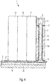
- FIG. 4 shows a longitudinal section through the cell module 1.
- a cooling channel system 14 On the cooling plate 5, in the interior of which a cooling channel system 14 is provided, a plurality of memory cells 15 to 17 are arranged one behind the other nested. Bottoms of the memory cells 15-17 may be glued to a top surface of the cooling plate 5, for example via a thermally conductive adhesive.
- the cell packet formed by the memory cells is connected by means of the clamping bands 3, 4 (cf. FIG. 1 ) connected together pressure plates, of which only the pressure plate 2 is shown here.
- an insulating layer 16 may be introduced, which thermally insulated the housing relative to the pressure plate 2.
- the pressure plate 2 is on top of the cooling plate 5, wherein between a bottom of the pressure plate 2 and the top of the cooling plate 5, a thermal insulation 16 may be provided.
- the flange 8 of the inlet 6 is also seated on a thermal insulation 17 on an upper side of the pressure plate 2.
- the inlet 6 is in fluid communication with the cooling channel system 14 via the connecting channel 10.
- the pressure plate 2 are provided in the pressure plate 2 from top to bottom passing channels, of which only a channel 18 can be seen here, in which the connecting channel 10 is inserted.
- the connecting channel 10 does not touch the channel 18, in particular not directly, with the result that the connecting channel 10 is well insulated from the channel 18 and the pressure plate 2 thermally. Thus, none of the fluid-conducting components 5, 8, 10 etc. is in direct contact with the printing plate.
- FIG. 4 only partially shown cell module 1 is arranged in a storage housing, of which in FIG. 4 only a portion 19 of the housing bottom can be seen. Between an underside of the cooling plate 5 of the cell module 1 and an upper side of the storage case bottom 19, an insulation 20 is provided. The insulation 20 ensures that the cooling plate 5 does not cool the storage housing or the storage housing bottom 19.
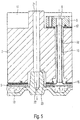
- FIG. 5 shows one to the sectional view of FIG. 4 vertical section through the cell module and that in the region of the connecting channel 10.
- the pressure plate 2 has a bore 21, the Receiving a screw or threaded rod is provided, via which the pressure plate 2 can be screwed to the storage case bottom 19.
- a corresponding threaded bore 22 is provided in the storage case bottom 19.
- the pressure plate 2 is clamped directly to the storage case bottom 19.
- insulation is also provided in a region in which the pressure plate 2 rests on a support 19a projecting upwards from the storage housing bottom 19.
- a thermally insulating element can be installed between the pressure plate 2 and the storage housing 19, which must be "hard” for a screw connection of the arrangement or may not flow.
Landscapes
- Engineering & Computer Science (AREA)
- Chemical & Material Sciences (AREA)
- Chemical Kinetics & Catalysis (AREA)
- Electrochemistry (AREA)
- General Chemical & Material Sciences (AREA)
- Manufacturing & Machinery (AREA)
- Sustainable Energy (AREA)
- Sustainable Development (AREA)
- Life Sciences & Earth Sciences (AREA)
- Power Engineering (AREA)
- Transportation (AREA)
- Mechanical Engineering (AREA)
- Aviation & Aerospace Engineering (AREA)
- Secondary Cells (AREA)
- Battery Mounting, Suspending (AREA)
- Cooling Or The Like Of Electrical Apparatus (AREA)
Description
- Die vorliegende Erfindung betrifft eine Vorrichtung zur Spannungsversorgung gemäß dem Oberbegriff des Patentanspruches 1.
- Eine derartige Vorrichtung ist aus der
US 2011/0020676 A1 bekannt. Zum technischen Hintergrund der vorliegenden Erfindung zählen dieEP 2 362 464 A1 ,JP 2011 034775 A DE 102 38 235 A1 sowie dieDE 10 2008 034 874 A1 . - Hybridfahrzeuge und reine Elektrofahrzeuge benötigen Hybridfahrzeuge und reine Elektrofahrzeuge benötigen für den Fahrzeugantrieb einen leistungsfähigen elektrischen Energiespeicher. Mehrere "Speicherelemente" bzw. Speicherzellen können zu einem sogenannten "Zellmodul" verschaltet sein. Ein Energiespeicher wiederum kann aus mehreren derartigen Zellmodulen bestehen. In einem elektrischen Energiespeicher können während des Betriebs beträchtliche Wärmeleistungen entstehen. Um ein "Überhitzen" des Energiespeichers zu vermeiden, ist daher zumindest in manchen Betriebszuständen eine aktive Kühlung erforderlich. Aufgabe der Erfindung ist es, eine Vorrichtung zur Spannungsversorgung zu schaffen, die eine Kühleinrichtung aufweist, welche möglichst einfach und kompakt aufgebaut und in einfacher Weise an einen Kühl- bzw. Kältemittelkreislauf anschließbar ist. Diese Aufgabe wird durch die Merkmale des Patentanspruches 1 gelöst. Vorteilhafte Ausgestaltungen und Weiterbildungen der Erfindung sind den Unteransprüchen zu entnehmen. Ausgangspunkt der Erfindung ist eine Vorrichtung zur Spannungsversorgung, insbesondere zur Spannungsversorgung eines Elektroantriebs eines Kraftfahrzeugs. Die Vorrichtung weist ein Zellmodul auf, welches wiederum mehrere miteinander elektrisch verschaltete Speicherzellen aufweist. Die einzelnen Speicherzellen können z.B. in einer Reihe hintereinander, in einem Rechteckraster, oder in anderer Weise relativ zueinander angeordnet sein. Sie weisen eckige Gehäuse auf. Hintereinander angeordnete Speicherzellen eines Zellmoduls sind zwischen einem ersten und einem zweiten plattenartigen Element angeordnet. Die plattenartigen Elemente können als "Druckplatten" bezeichnet werden. Die Druckplatten sind mittels Spannelementen (sogenannten "Spannbändern") zusammengespannt. Dadurch wird vermieden, dass sich das Zellmodul im Betrieb in nennenswertem Umfang deformiert.
- Die Speicherzellen eines Zellmoduls sind auf einem plattenartigen Kühlkörper angeordnet und thermisch leitend mit dem plattenartigen Kühlkörper verbunden. Es kann vorgesehen sein, dass Längsachsen der Speicherzellen senkrecht auf dem plattenartigen Kühlkörper stehen. Unterseiten der Speicherzellen sind mittels eines thermisch leitenden Klebers mit dem Kühlkörper verbunden. Die Seitenflächen der Speicherzellen können z.B. mittels eines thermisch leitenden Klebers mit dem Kühlkörper verbunden sein. In dem Kühlkörper ist ein Kühlkanalsystem vorgesehen, das mindestens einen Zulauf und mindestens einen Ablauf aufweist. Das Kühlkanalsystem kann von einem Kühlmittel bzw. einem Kältemittel durchströmt sein. Unter dem Begriff "Kühlmittel" versteht man in diesem Zusammenhang ein in jedem Betriebszustand flüssiges Kühlmittel. Unter dem Begriff "Kältemittel" versteht man eine Substanz, die während des Betriebs teilweise oder ganz einen flüssigen und/oder gasförmigen Zustand annehmen kann, je nach den momentanen Temperatur- und Druckverhältnissen. Das Kühlkanalsystem des Kühlkörpers kann somit beispielsweise an einen Kältemittelkreislauf einer Fahrzeugklimaanlage angeschlossen sein.
- Der Kern der Erfindung besteht darin, dass der mindestens eine Zulauf und/oder der mindestens eine Ablauf des Kühlkanalsystems im Bereich einer "Oberseite" des ersten und/oder des zweiten plattenartigen Elements angeordnet ist.
- "Im Bereich einer Oberseite" bedeutet, in einem Bereich, der von dem plattenartigen Kühlkörper zumindest ein Stück weit beabstandet ist bzw. dem plattenartigen Kühlkörper abgewandt ist. Vorzugsweise sind der Zulauf und der Ablauf an einer Oberseite des ersten und/oder des zweiten plattenartigen Elements und somit tatsächlich von dem plattenartigen Kühlkörper abgewandt angeordnet. Eine Anordnung des Zulaufs und des Ablaufs im Bereich der Oberseite eines der plattenartigen Elemente oder der plattenartige Elemente hat den Vorteil, dass ein erstes Zellmodul unmittelbar an ein zweites Zellmodul "gereiht" werden kann. Eine Zugänglichkeit des Zulaufs und des Ablaufs von "oben her" erleichtert ferner die Montage bzw. den Anschluss an ein Kühl- oder Kältemittelsystem an einen Kühl- oder Kältemittelkreislauf, insbesondere wenn mindestens ein Zellmodul bereits in einem bauraumoptimierten Gehäuse untergebracht ist. Erfindungsgemäß ist in (im Sinne von im Innern) dem ersten und/oder dem zweiten plattenartigen Element ein sich von dem Kühlkanalsystem des plattenartigen Kühlkörpers zu dem Zulauf und ein von dem Kühlkanalsystem zu dem Ablauf erstreckender (Verbindungs-)Kanal vorgesehen. Nach einer Weiterbildung der Erfindung ist an dem ersten und/oder dem zweiten plattenartigen Element ein sich von dem Kühlkanalsystem des plattenartigen Kühlkörpers zu dem Zulauf und ein von dem Kühlkanalsystem zu dem Ablauf erstreckender (Verbindungs-)Kanal vorgesehen. Begrifflich unterschieden wird bei einer derartigen Anordnung das in dem plattenartigen Kühlkörper integrierte Kühlkanalsystem, der Zulauf und der Ablauf sowie Verbindungskanäle, über die der Zulauf bzw. der Ablauf mit dem Kühlkanalsystem verbunden sind.
- In (im Sinne von innerhalb) oder an dem ersten und/oder dem zweiten plattenartigen Element kann ein sich von dem Kühlkanalsystem zu dem Zulauf und ein sich von dem Kühlkanalsystem zu dem Ablauf erstreckender Kanal vorgesehen sein.
- Nach einer Weiterbildung der Erfindung bildet der sich von dem Kühlkanalsystem zu dem Zulauf erstreckende Kanal den ersten Verbindungskanal und der sich von dem Kühlkanalsystem zu dem Ablauf erstreckende Kanal den zweiten Verbindungskanal, wobei Kühl- bzw. Kältemittel unmittelbar in diesen Kanälen strömt. Sofern diese Kanäle in das erste und/oder das zweite plattenartige Element integriert sind, kann vorgesehen sein, dass das Kühl-oder Kältemittel unmittelbar in diesen Kanälen, d.h. unmittelbar in dem bzw. den plattenartigen Element(en) strömt.
- Der Zulauf und/oder der Ablauf können integraler Bestandteil des ersten bzw. des zweiten plattenartigen Elements sein. Alternativ dazu können der Zulauf und/oder der Ablauf durch separate Flanschelemente realisiert sein, die mit den Verbindungskanälen verbunden sind.
- Alternativ dazu kann vorgesehen sein, dass es sich bei den Verbindungskanälen, welche das in dem plattenartigen Kühlkörper vorgesehene Kühlkanalsystem mit dem Zulauf bzw. dem Ablauf verbinden, um separate Bauteile handelt, die in den Kanälen, die an oder in dem ersten und/oder dem zweiten plattenartigen Element vorgesehen sind, angeordnet sind. Eine Anordnung der Verbindungskanäle in den Kanälen, die in oder an dem ersten und/oder zweiten plattenartigen Element vorgesehen sind, hat den Vorteil, dass die Verbindungskanäle gegenüber den Kanälen thermisch isoliert sein können. Vorzugsweise sind die Verbindungskanäle in den Kanälen so angeordnet, dass sie die Kanäle nicht unmittelbar berühren.
- Die Verbindungskanäle können stoffschlüssig mit dem Kühlkanalsystem verbunden sein. Ihre einen Enden können z. B. mit einem Auslass bzw. mit einem Einlass des Kühlkanalsystems verlötet sein. Ebenso können der Zulauf und der Ablauf stoffschlüssig mit anderen Enden der Verbindungskanäle verbunden sein, z. B. durch Lötverbindungen.
- Ein oder mehrere der oben beschriebenen Zellmodule können in ein Speicher- bzw. Batteriegehäuse eingesetzt sein. Jedem der Zellmodule ist ein separater Kühlkörper zugeordnet. Vorzugsweise ist der Kühlkörper eines Zellmoduls thermisch gegenüber dem Speichergehäuse isoliert. Dies kann insbesondere dadurch erreicht werden, dass der Kühlkörper eines Zellmoduls das Speichergehäuse nicht unmittelbar berührt. Zwischen eine Unterseite eines Kühlkörpers eines Zellmoduls und eine Oberseite eines Bodens des Speichergehäuses können z.B. thermisch schlecht leitende (d.h. thermisch isolierende) Abstandshalter oder eine flächige Isolierschicht eingebracht sein. Die Abstandshalter bzw. die Isolierschicht können insbesondere elastisch sein.
- Alternativ dazu kann vorgesehen sein, dass die plattenartigen Elemente, welche die Speicherzellen eines Zellmoduls zusammenspannen, über Auflager auf dem Boden des Speichergehäuses aufliegen bzw. aufstehen und thermisch von dem Kühlkörper entkoppelt sind.
- Im Folgenden wird die Erfindung im Zusammenhang mit der Zeichnung näher erläutert. Es zeigen:
- Figur 1
- Ein Zellmodul gemäß der Erfindung in perspektivischer Darstellung;
- Figur 2
- einen Kühlkörper eines Zellmoduls mit davon abstehenden Verbindungskanälen und einem Zulauf und einem Ablauf;
- Figur 3
- den Kühlkörper der
Figur 2 mit einer auf die Verbindungskanäle aufgeschobenen Druckplatte; - Figur 4
- einen Längsschnitt durch ein Zellmodul gemäß der Erfindung;
- Figur 5
- einen zu dem Längsschnitt der Figur senkrechten Schnitt durch eine Druckplatte eines Zellmoduls.
-
Figur 1 zeigt ein Zellmodul 1 eines hier nicht näher dargestellten elektrischen Energiespeichers, der zur Spannungsversorgung des Elektroantriebs eines Kraftfahrzeugs vorgesehen sein kann. - Das Zellmodul 1 weist an seinen Stirnseiten jeweils eine Druckplatte auf, von denen hier lediglich die vordere Druckplatte 2 zu sehen ist. Zwischen den Druckplatten sind hier nicht näher zu erkennende Speicherzellen geschachtelt hintereinander angeordnet. Die Druckplatten sind auf einer Vorder- und einer Rückseite des Zellmoduls 1 über Spannplatten, die im Folgenden auch als "Spannbänder" 3, 4 bezeichnet werden, in Längsrichtung des Zellmoduls 1 zusammengespannt.
- Die in
Figur 1 nur im unteren Bereich des Zellmoduls 1 erkennbaren Speicherzellen 15, 16, 17 etc. stehen auf einer Kühlplatte 5 auf. Unterseiten der Speicherzellen können über einen thermisch leitenden Kleber oder in anderer Weise gut thermisch leitend mit der Kühlplatte 5 verbunden sein. - Im Innern der Kühlplatte 5 ist ein hier nicht näher dargestelltes Kühlkanalsystem vorgesehen, das z.B. von einem Kühlmittel oder einem Kältemittel durchströmt sein kann. Das Kühlkanalsystem der Kühlplatte 5 steht in Fluidverbindung mit einem Kühlmittelzulauf 6 und einem Kühlmittelablauf 7, die in einem "oberen Bereich", hier an einer Oberseite der vorderen Druckplatte 2, angeordnet sind. Über den Kühlmittelzulauf und den Kühlmittelablauf kann das in die Kühlplatte 5 integrierte Kühlkanalsystem an einen Kühl- oder Kältemittelkreislauf eines Fahrzeugs angeschlossen werden, so dass die Speicherzellen des Zellmoduls 1 aktiv gekühlt werden können.
- An der in
Figur 1 nicht zu erkennenden hinteren Stirnseite des Zellmoduls kann ebenfalls ein Kühlmittelzulauf und ein Kühlmittelablauf vorgesehen sein. -
Figur 2 zeigt die Kühlplatte 5 derFigur 1 in Einzeldarstellung. Der Kühlmittelzulauf 6 ist durch ein erstes Flanschelement 8 gebildet. Der Kühlmittelablauf 7 ist durch ein zweites Flanschelement 9 gebildet. An Unterseiten der beiden Flanschelemente 8, 9 ist ein erster bzw. zweiter Verbindungskanal 10, 11 angelötet. Die Flanschelemente können auch in anderer Weise in Fluidverbindung mit den Verbindungskanälen 10, 11 stehen. Die Verbindungskanäle könnten z.B. mit den Flanschelementen verschraubt sein. Untere Enden der Verbindungskanäle 10, 11 wiederum sind hier stoffschlüssig, z.B. über Lötverbindungen mit dem im Innern der Kühlplatte 5 vorgesehenen Kühlkanalsystem verbunden. - Über den Kühlmittelzulauf 6 kann Kühl- oder Kältemittel in das Kühlkanalsystem der Kühlplatte 5 gepumpt und über den Kühlmittelablauf 7 erwärmtes bzw. erhitztes Kühl- oder Kältemittel aus dem Kühlkanalsystem abgeführt werden.
-
Figur 3 zeigt die Kühlplatte 5 derFigur 2 mit "aufgesetzter" Druckplatte 2. Die Druckplatte 2 weist ein linkes und ein rechts Auflager 12 bzw. 13 auf, welches zur Befestigung im Gehäuse durch die Kühlplatte 5 hindurch ragt. Alternativ dazu können die Auflager 12 bzw. 13 auch weiter oben innerhalb der Druckplatte liegen und dort mit dem Speichergehäuse verbunden sein (vgl.Fig. 5 ). - In der Druckplatte 2 ist ein dem Verbindungskanal 10 zugeordneter erster Kanal und ein dem Verbindungskanal 11 zugeordneter zweiter Kanal (nicht dargestellt) vorgesehen. Die beiden Kanäle durchsetzen die Druckplatte 2 von unten nach oben. Bei der Montage des Zellmoduls werden zunächst die Verbindungskanäle 10, 11 an die zugeordneten Fluidverbindungen des Kühlkanalsystems der Kühlplatte 5 angelötet. Anschließend wird die Druckplatte 2 aufgesetzt, wobei die Verbindungskanäle 10, 11 in die in der Druckplatte 2 vorgesehenen Kanäle eingeführt werden. Anschließend werden die Flanschelemente 8, 9 mit den oberen Enden der Verbindungskanäle 10, 11 verbunden.
- Alternativ dazu sind die Kanäle in der Druckplatte zu einer Seite hin offen oder die Druckplatte ist zweiteilig, um die Platte auch nachdem die Flansche 8, 9 mit den Kanälen verbunden wurden (vgl.
Fig. 2 ), montieren zu können. - In gleicher Weise wird auch die hintere Druckplatte (nicht dargestellt) montiert. Vor oder nach der Montage der Druckplatten können die einzelnen Speicherzellen auf die Oberseite der Kühlplatte 5 gestellt bzw. mit der Kühlplatte 5 verklebt werden.
-
Figur 4 zeigt einen Längsschnitt durch das Zellmodul 1. Auf die Kühlplatte 5, in deren Innerem ein Kühlkanalsystem 14 vorgesehen ist, sind hintereinander geschachtelt mehrere Speicherzellen 15 bis 17 angeordnet. Unterseiten der Speicherzellen 15 - 17 können z.B. über einen thermisch leitenden Kleber mit einer Oberseite der Kühlplatte 5 verklebt sein. - Wie bereits erwähnt, wird das durch die Speicherzellen gebildete Zellpaket mittels der über die Spannbänder 3, 4 (vgl.
Figur 1 ) miteinander verbundenen Druckplatten zusammengespannt, von denen hier lediglich die Druckplatte 2 dargestellt ist. - Zwischen die das Gehäuse der Speicherzelle 17 und die Druckplatte 2 kann eine Isolierschicht 16 eingebracht sein, welche das Gehäuse gegenüber der Druckplatte 2 thermisch isoliert.
- Wie aus
Figur 4 ersichtlich ist, steht die Druckplatte 2 auf einer Oberseite der Kühlplatte 5 auf, wobei zwischen einer Unterseite der Druckplatte 2 und der Oberseite der Kühlplatte 5 eine thermische Isolierung 16 vorgesehen sein kann. Das Flanschelement 8 des Zulaufs 6 sitzt ebenfalls über eine thermische Isolierung 17 auf einer Oberseite der Druckplatte 2 auf. - Wie bereits erwähnt, steht der Zulauf 6 über dem Verbindungskanal 10 mit dem Kühlkanalsystem 14 in Fluidverbindung.
- Bei dem in
Figur 4 gezeigten Ausführungsbeispiel sind in der Druckplatte 2 die Druckplatte 2 von oben nach unten durchsetzende Kanäle vorgesehen, von denen hier lediglich ein Kanal 18 zu sehen ist, in den der Verbindungskanal 10 eingeschoben ist. - Wie aus
Figur 4 ersichtlich ist, berührt der Verbindungskanal 10 den Kanal 18 nicht, insbesondere nicht unmittelbar, was zur Folge hat, dass der Verbindungskanal 10 gut gegenüber dem Kanal 18 bzw. der Druckplatte 2 thermisch isoliert ist. Somit steht keines der fluidleitenden Bauteile 5, 8, 10 etc. in direktem Kontakt mit der Druckplatte. - Das in
Figur 4 nur teilweise dargestellte Zellmodul 1 ist in einem Speichergehäuse angeordnet, von dem inFigur 4 lediglich ein Teilabschnitt 19 des Gehäusebodens zu erkennen ist. Zwischen einer Unterseite der Kühlplatte 5 des Zellmoduls 1 und einer Oberseite des Speichergehäusebodens 19 ist eine Isolierung 20 vorgesehen. Durch die Isolierung 20 wird sichergestellt, dass die Kühlplatte 5 nicht das Speichergehäuse bzw. den Speichergehäuseboden 19 kühlt. -
Figur 5 zeigt einen zu der Schnittdarstellung derFigur 4 senkrechten Schnitt durch das Zellmodul und zwar im Bereich des Verbindungskanals 10. Zusätzlich zu den Kanälen, welche zur Aufnahme der Verbindungskanäle vorgesehen sind, weist die Druckplatte 2 eine Bohrung 21 auf, die zur Aufnahme einer Schraube bzw. Gewindestange vorgesehen ist, über die die Druckplatte 2 mit dem Speichergehäuseboden 19 verschraubt werden kann. Hierzu ist in dem Speichergehäuseboden 19 eine entsprechende Gewindebohrung 22 vorgesehen. Durch eine Schraube bzw. Gewindestange wird die Druckplatte 2 unmittelbar mit dem Speichergehäuseboden 19 verspannt. Die Kleberschicht, welche die Unterseiten der Speicherzellen 15 - 17 mit der Oberseite der Kühlplatte 5 verbindet, wird hierdurch nicht beeinträchtigt. Vorzugsweise ist in einem Bereich, in dem die Druckplatte 2 auf einem vom Speichergehäuseboden 19 nach oben abstehenden Auflager 19a aufliegt, ebenfalls eine Isolierung vorgesehen. - Um die Druckplatte 2 darüber hinaus thermisch von dem Speichergehäuse zu entkoppeln, beispielsweise wenn der Verbindungskanal 10 von der Druckplatte 2 nicht thermisch entkoppelt bzw. in die Druckplatte 2 integriert ist, kann zwischen die Druckplatte 2 und das Speichergehäuse 19 ein thermisch isolierendes Element eingebaut werden, welches für eine Verschraubung der Anordnung "hart" sein muss bzw. nicht fließen darf.
Claims (11)
- Vorrichtung zur Spannungsversorgung, insbesondere zur Spannungsversorgung eines Kraftfahrzeugs, mit- einem Zellmodul (1), das mehrere Speicherzellen (15-17) aufweist, die zwischen einem ersten und einem zweiten plattenartigen Element (2) angeordnet sind, wobei Gehäuse der Speicherzellen (15-17) eckig sind,- einem mit Unterseiten der Speicherzellen (15-17) thermisch leitend verbundenen, plattenartigen Kühlkörper (5), in dessen Innerem ein Kühlkanalsystem (14) vorgesehen ist, das in Fluidverbindung mit mindestens einem Kühl-/Kältemittelzulauf (6) und mindestens einem Kühl-/Kältemittelablauf (7) steht,wobei der mindestens eine Kühl-/Kältemittelzulauf (6) und/oder der mindestens eine Kühl-/Kältemittelablauf (7) im Bereich einer dem plattenartigen Kühlkörper (5) abgewandten Oberseite des ersten und/oder des zweiten plattenartigen Elements (2) angeordnet ist, dadurch gekennzeichnet, dass
die plattenartigen Elemente (2) jeweils über ein linkes und ein rechtes Spannelement (3, 4) miteinander verbunden sind, wobei die Speicherzellen (15-17) des Zellmoduls (1) mittels der Spannelemente (3, 4) zwischen den plattenartigen Elementen (2) eingespannt sind, die Unterseiten der Speicherzellen (15-17) über einen thermisch leitenden Kleber mit dem plattenartigen Kühlkörper (5) verbunden sind und
in dem ersten und/oder dem zweiten plattenartigen Element (2) ein sich von dem Kühlkanalsystem (14) zu dem Kühl-/Kältemittelzulauf (6) und ein weiterer sich von dem Kühlkanalsystem (14) zu dem Kühl-/Kältemittelablauf (7) erstreckender Kanal (18) vorgesehen ist. - Vorrichtung nach Anspruch 1,
dadurch gekennzeichnet, dass der Kühl-/Kältemittelzulauf (6) über mindestens einen ersten und der Kühl-/Kältemittelablauf (7) über
mindestens einen zweiten Verbindungskanal (10, 11) mit dem Kühlkanalsystem (14) verbunden ist. - Vorrichtung nach Anspruch 1 oder 2,
dadurch gekennzeichnet, dass der sich von dem Kühlkanalsystem (14) zu dem Kühl-/Kältemittelzulauf (6) erstreckende Kanal den ersten Verbindungskanal bildet und der sich von dem Kühlkanalsystem (14) zu dem Kühl-/Kältemittelablauf (7) erstreckende Kanal den zweiten Verbindungskanal bildet, wobei Kühl- oder Kältemittel unmittelbar in den Kanälen (18) strömt. - Vorrichtung nach einem der vorangehenden Ansprüche,
dadurch gekennzeichnet, dass der Kühl-/Kältemittelzulauf (6) und/oder der Kühl-/Kältemittelablauf (7) integraler Bestandteil des ersten oder des zweiten plattenartigen Elements (2) ist. - Vorrichtung nach einem der Ansprüche 3 bis 5,
dadurch gekennzeichnet, dass die Verbindungskanäle (10, 11) separate Bauteile sind, die in den Kanälen (18) angeordnet sind. - Vorrichtung nach einem der Ansprüche 2 bis 6,
dadurch gekennzeichnet, dass die Verbindungskanäle (10, 11) stoffschlüssig mit dem Kühlkanalsystem (14) verbunden sind. - Vorrichtung nach einem der Ansprüche 2 bis 7,
dadurch gekennzeichnet, dass der Kühl-/Kältemittelzulauf (6) und der Kühl-/Kältemittelablauf (7) durch Flanschelemente gebildet sind, die jeweils mit einem der Verbindungskanäle (10) verbunden sind oder dass die Flanschelemente integraler Bestandteil des ersten bzw. zweiten plattenartigen Elements (2) sind. - Vorrichtung nach Anspruch 5,
dadurch gekennzeichnet, dass die Verbindungskanäle (10, 11) gegenüber den Kanälen (18), in denen sie angeordnet sind, thermisch isoliert sind, derart, dass die Verbindungskanäle (10, 11) die Kanäle (18) nicht unmittelbar berühren. - Vorrichtung nach einem der vorangehenden Ansprüche,
dadurch gekennzeichnet, dass das Zellmodul (1) und der Kühlkörper (5) in ein Speichergehäuse (19) eingesetzt sind, wobei der Kühlkörper (5) gegenüber dem Speichergehäuse (19) thermisch isoliert ist, derart, dass er das Speichergehäuse (19) nicht unmittelbar berührt. - Vorrichtung nach Anspruch 9,
dadurch gekennzeichnet, dass die plattenartigen Elemente (2) über Auflager (12, 13) auf einem Boden (19) des Speichergehäuses aufstehen. - Vorrichtung nach einem der Ansprüche 2 bis 10,
dadurch gekennzeichnet, dass das Kühlkanalsystem (14), die Verbindungskanäle (10, 11), der Kühl-/Kältemittelzulauf (6) und der Kühl-/Kältemittelablauf (7) für eine Durchströmung mit einem Kältemittel bestimmt und geeignet sind.
Applications Claiming Priority (2)
| Application Number | Priority Date | Filing Date | Title |
|---|---|---|---|
| DE102011084660.3A DE102011084660B4 (de) | 2011-10-18 | 2011-10-18 | Vorrichtung zur Spannungsversorgung |
| PCT/EP2012/068482 WO2013056938A1 (de) | 2011-10-18 | 2012-09-20 | Vorrichtung zur spannungsversorgung |
Publications (2)
| Publication Number | Publication Date |
|---|---|
| EP2769426A1 EP2769426A1 (de) | 2014-08-27 |
| EP2769426B1 true EP2769426B1 (de) | 2017-05-17 |
Family
ID=47008529
Family Applications (1)
| Application Number | Title | Priority Date | Filing Date |
|---|---|---|---|
| EP12770028.4A Active EP2769426B1 (de) | 2011-10-18 | 2012-09-20 | Vorrichtung zur spannungsversorgung |
Country Status (5)
| Country | Link |
|---|---|
| US (1) | US9356328B2 (de) |
| EP (1) | EP2769426B1 (de) |
| CN (1) | CN103650200B (de) |
| DE (1) | DE102011084660B4 (de) |
| WO (1) | WO2013056938A1 (de) |
Families Citing this family (51)
| Publication number | Priority date | Publication date | Assignee | Title |
|---|---|---|---|---|
| DE102012211180A1 (de) * | 2012-06-28 | 2014-04-03 | Bayerische Motoren Werke Aktiengesellschaft | Energiespeichermodul aus mehreren prismatischen Speicherzellen |
| DE102014203942A1 (de) * | 2014-03-05 | 2015-09-10 | Robert Bosch Gmbh | Vorrichtung zur Temperierung von Batterien |
| DE102015207666A1 (de) * | 2015-04-27 | 2016-10-27 | Bayerische Motoren Werke Aktiengesellschaft | Batteriemodul und Hochvoltspeicher |
| DE102015210892A1 (de) * | 2015-06-15 | 2016-12-15 | Volkswagen Aktiengesellschaft | Anordnung, Vorrichtung und Verfahren zur Befestigung zumindest einer Energiespeichereinrichtung sowie Bodenplatte |
| DE102015221265A1 (de) | 2015-10-30 | 2017-05-04 | Bayerische Motoren Werke Aktiengesellschaft | Fluiddurchströmbarer Kühlkörper für elektrische Energiespeicher |
| DE102016202912A1 (de) * | 2016-02-25 | 2017-08-31 | Bayerische Motoren Werke Aktiengesellschaft | Zellmodul für eine Batterie eines Kraftfahrzeugs sowie Verfahren zum Herstellen eines solchen Zellmoduls |
| EP3291358A1 (de) * | 2016-08-31 | 2018-03-07 | Akasol GmbH | Battery module assembly and cooling plate for use in a battery module assembly |
| DE102016223063A1 (de) | 2016-11-22 | 2018-05-24 | Bayerische Motoren Werke Aktiengesellschaft | Die Erfindung betrifft ein Zellmodul |
| DE102017204763A1 (de) * | 2017-03-22 | 2018-09-27 | Bayerische Motoren Werke Aktiengesellschaft | Hochvoltspeicher |
| DE102017106899A1 (de) * | 2017-03-30 | 2018-10-04 | Dr. Ing. H.C. F. Porsche Aktiengesellschaft | Batteriemodul für eine Traktionsbatterie |
| DE102017206185B4 (de) * | 2017-04-11 | 2018-11-08 | Audi Ag | Batterie für ein Kraftfahrzeug und Kraftfahrzeug |
| DE102017208617A1 (de) * | 2017-05-22 | 2018-11-22 | Bayerische Motoren Werke Aktiengesellschaft | Energiespeichergehäuse mit einem Kühlungsanschluss, Energiespeicher und Kraftfahrzeug mit einem solchen |
| US20190088978A1 (en) * | 2017-09-15 | 2019-03-21 | Dyson Technology Limited | Continuous manufacturing of stacked electrochemical device with polymer interlayer |
| CN109599621A (zh) * | 2017-09-30 | 2019-04-09 | 浙江三花汽车零部件有限公司 | 冷却板集成组件和电池组件 |
| FR3075470B1 (fr) * | 2017-12-20 | 2021-07-30 | Valeo Systemes Thermiques | Element de refroidissement d'un dispositif de stockage electrique pour vehicule automobile. |
| FR3079672B1 (fr) | 2018-03-27 | 2020-03-06 | Valeo Systemes Thermiques | Systeme de refroidissement de cellules de batterie de vehicule automobile |
| FR3062749B1 (fr) * | 2018-04-10 | 2023-04-14 | Sogefi Air & Cooling | Unite de batterie integrant des zones d'echanges thermiques |
| DE102018210444B3 (de) * | 2018-06-27 | 2019-05-09 | Bayerische Motoren Werke Aktiengesellschaft | Hochvoltbatterie für ein Kraftfahrzeug sowie Kraftfahrzeug |
| FR3086803A1 (fr) | 2018-10-02 | 2020-04-03 | Valeo Systemes Thermiques | Systeme de refroidissement de cellules de batterie de vehicule automobile |
| FR3095553A1 (fr) | 2019-04-25 | 2020-10-30 | Valeo Systemes Thermiques | Enveloppe pour un module de stockage d’énergie électrique |
| DE102019207001A1 (de) * | 2019-05-14 | 2020-11-19 | Audi Ag | Kühlmittelrohranordnung, Hochvoltenergiespeicher, Kraftfahrzeug und Verfahren zum Herstellen einer Kühlmittelrohranordnung |
| FR3097079A1 (fr) | 2019-06-06 | 2020-12-11 | Valeo Systemes Thermiques | Enveloppe pour un module de stockage d’énergie électrique |
| FR3099646B1 (fr) * | 2019-07-30 | 2021-07-02 | Sogefi Air & Cooling | Module et dispositif de refroidissement pour batterie et batterie correspondante |
| HUE059810T2 (hu) * | 2019-08-01 | 2022-12-28 | Samsung Sdi Co Ltd | Akkumulátor modul többfunkciós véglemezzel |
| CN210576067U (zh) | 2019-08-09 | 2020-05-19 | 宁德时代新能源科技股份有限公司 | 电池模组 |
| FR3103968A1 (fr) | 2019-11-28 | 2021-06-04 | Valeo Systemes Thermiques | Compartiment pour un équipement susceptible de dégager de la chaleur |
| FR3104830B1 (fr) | 2019-12-12 | 2022-05-20 | Valeo Systemes Thermiques | Compartiment pour un équipement susceptible de dégager de la chaleur |
| FR3104831A1 (fr) | 2019-12-16 | 2021-06-18 | Valeo Systemes Thermiques | Compartiment pour un équipement susceptible de dégager de la chaleur |
| FR3104832B1 (fr) | 2019-12-17 | 2022-06-24 | Valeo Systemes Thermiques | Compartiment pour un équipement susceptible de dégager de la chaleur |
| CN111146856B (zh) * | 2020-01-19 | 2020-10-30 | 国网上海市电力公司 | 一种大小功率切换供电装置 |
| FR3106700B1 (fr) | 2020-01-27 | 2022-06-17 | Valeo Systemes Thermiques | Compartiment pour un équipement susceptible de dégager de la chaleur |
| FR3106699A1 (fr) | 2020-01-27 | 2021-07-30 | Valeo Systemes Thermiques | Compartiment pour un équipement susceptible de dégager de la chaleur |
| DE102020103954A1 (de) | 2020-02-14 | 2021-08-19 | Bayerische Motoren Werke Aktiengesellschaft | Batterie für ein Kraftfahrzeug |
| FR3107398A1 (fr) | 2020-02-17 | 2021-08-20 | Valeo Systemes Thermiques | Compartiment pour un équipement susceptible de dégager de la chaleur |
| KR102950794B1 (ko) * | 2020-04-13 | 2026-04-08 | 주식회사 엘지에너지솔루션 | 전지 모듈 및 그 제조 방법 |
| KR102805880B1 (ko) * | 2020-06-02 | 2025-05-12 | 주식회사 엘지에너지솔루션 | 팩 케이스에 냉매 순환로가 구비한 전지 팩 |
| CN111640895A (zh) * | 2020-06-09 | 2020-09-08 | 博戈橡胶塑料(株洲)有限公司 | 一种新能源汽车电池箱 |
| CN212648376U (zh) * | 2020-07-29 | 2021-03-02 | 厦门海辰新能源科技有限公司 | 一种电池箱体和电池包 |
| DE102020121205A1 (de) * | 2020-08-12 | 2022-02-17 | Dr. Ing. H.C. F. Porsche Aktiengesellschaft | Batteriegehäuse für eine Kraftfahrzeugbatterie |
| FR3113725A1 (fr) | 2020-08-25 | 2022-03-04 | Valeo Systemes Thermiques | Compartiment pour un équipement susceptible de dégager de la chaleur |
| FR3114916A1 (fr) | 2020-10-07 | 2022-04-08 | Valeo Systemes Thermiques | Composant pour un module de stockage d’énergie électrique |
| FR3116328B1 (fr) | 2020-11-19 | 2022-12-23 | Valeo Systemes Thermiques | Compartiment pour un équipement susceptible de dégager de la chaleur |
| KR102890295B1 (ko) * | 2021-01-11 | 2025-11-21 | 주식회사 엘지에너지솔루션 | 전지 모듈 및 이를 포함하는 전지팩 |
| CN112928364B (zh) * | 2021-02-09 | 2022-04-29 | 合肥国轩高科动力能源有限公司 | 动力电池模组壳体 |
| FR3121790A1 (fr) | 2021-04-09 | 2022-10-14 | Valeo Systemes Thermiques | Compartiment pour un équipement susceptible de dégager de la chaleur |
| FR3121789A1 (fr) | 2021-04-09 | 2022-10-14 | Valeo Systemes Thermiques | Compartiment pour un équipement susceptible de dégager de la chaleur |
| FR3125171A1 (fr) | 2021-07-08 | 2023-01-13 | Valeo Systemes Thermiques | Composant pour un module de stockage d’énergie électrique |
| FR3127849A1 (fr) | 2021-10-06 | 2023-04-07 | Valeo Systemes Thermiques | Compartiment pour un equipement susceptible de degager de la chaleur |
| CN113644360B (zh) * | 2021-10-19 | 2021-12-28 | 嘉兴模度新能源有限公司 | 一种具有热疏导功能的电池箱、热疏导结构及方法 |
| FR3130951B1 (fr) | 2021-12-16 | 2023-11-10 | Valeo Systemes Thermiques | Plaque de refroidissement |
| FR3131097B1 (fr) | 2021-12-16 | 2024-06-21 | Valeo Systemes Thermiques | Compartiment pour un équipement susceptible de dégager de la chaleur |
Citations (1)
| Publication number | Priority date | Publication date | Assignee | Title |
|---|---|---|---|---|
| US20110020676A1 (en) * | 2008-03-24 | 2011-01-27 | Sanyo Electric Co., Ltd. | Battery device and battery unit |
Family Cites Families (8)
| Publication number | Priority date | Publication date | Assignee | Title |
|---|---|---|---|---|
| FR2774215B1 (fr) * | 1998-01-29 | 2000-02-25 | Alsthom Cge Alcatel | Batterie monobloc etanche munie d'un dispositif de refroidissement |
| US7138205B2 (en) * | 2001-10-02 | 2006-11-21 | Matsushita Electric Industrial Co., Ltd. | Battery with proportional collectors, straps, and plates |
| DE10238235A1 (de) * | 2002-08-21 | 2004-03-04 | Daimlerchrysler Ag | Elektrochemischer Energiespeicher mit Wärmeaustauscherstruktur und mehreren elektrochemischen Speicherzellen |
| KR100949334B1 (ko) * | 2007-11-12 | 2010-03-26 | 삼성에스디아이 주식회사 | 전지 모듈 |
| DE102008034874B4 (de) * | 2008-07-26 | 2011-06-30 | Daimler AG, 70327 | Batterie und Verwendung einer Batterie |
| DE102009018787A1 (de) * | 2009-04-24 | 2010-10-28 | Akasol Engineering Gmbh | Batteriemodul |
| JP2011034775A (ja) * | 2009-07-31 | 2011-02-17 | Sanyo Electric Co Ltd | 組電池の冷却構造、及び、バッテリーシステム |
| US20110206967A1 (en) * | 2010-02-25 | 2011-08-25 | Sanyo Electric Co., Ltd. | Battery cooling/heating structure and battery module |
-
2011
- 2011-10-18 DE DE102011084660.3A patent/DE102011084660B4/de not_active Expired - Fee Related
-
2012
- 2012-09-20 CN CN201280031805.1A patent/CN103650200B/zh active Active
- 2012-09-20 WO PCT/EP2012/068482 patent/WO2013056938A1/de not_active Ceased
- 2012-09-20 EP EP12770028.4A patent/EP2769426B1/de active Active
-
2014
- 2014-03-11 US US14/204,000 patent/US9356328B2/en active Active
Patent Citations (1)
| Publication number | Priority date | Publication date | Assignee | Title |
|---|---|---|---|---|
| US20110020676A1 (en) * | 2008-03-24 | 2011-01-27 | Sanyo Electric Co., Ltd. | Battery device and battery unit |
Also Published As
| Publication number | Publication date |
|---|---|
| DE102011084660A1 (de) | 2013-04-18 |
| US20140193686A1 (en) | 2014-07-10 |
| WO2013056938A1 (de) | 2013-04-25 |
| EP2769426A1 (de) | 2014-08-27 |
| CN103650200B (zh) | 2016-10-12 |
| US9356328B2 (en) | 2016-05-31 |
| CN103650200A (zh) | 2014-03-19 |
| DE102011084660B4 (de) | 2018-02-15 |
Similar Documents
| Publication | Publication Date | Title |
|---|---|---|
| DE102011084660B4 (de) | Vorrichtung zur Spannungsversorgung | |
| DE112016000129B4 (de) | Wärmetauscher zum Kühlen eines elektrischen Elements, sowie Wärmetauscheranordnung und Kühlmodul | |
| EP2272311B1 (de) | Kühlvorrichtung für eine mehrzahl von leistungsmodulen | |
| EP2377184B1 (de) | Vorrichtung zur spannungsversorgung eines kraftfahrzeugs mit optimierter wärmeabführung | |
| EP2599153B1 (de) | Vorrichtung zur spannungsversorgung mit einer kühlanordnung | |
| EP2854212A1 (de) | Heiz- und Kühlvorrichtung für eine Batterie | |
| AT511117B1 (de) | Elektrischer energiespeicher | |
| DE102017202768A1 (de) | Energiespeicheranordnung und Kraftfahrzeug | |
| DE102018215477A1 (de) | Batteriesystem, Verfahren zum Temperieren und zur Druckbeaufschlagung wenigstens einer Batteriezelle eines Batteriemoduls eines derartigen Batteriesystems sowie Kraftfahrzeug mit einem derartigen Batteriesystem | |
| DE102011084536B4 (de) | Kühleinrichtung für einen elektrischen Energiespeicher und Energiespeichervorrichtung | |
| DE102014202542A1 (de) | Kühlvorrichtung, insbesondere für eine Batterie eines Kraftfahrzeugs | |
| WO2011134697A1 (de) | Batterie mit einer kühlplatte und kraftfahrzeug mit einer entsprechenden batterie | |
| WO2018036764A1 (de) | Kühlvorrichtung für eine batteriebaugruppe sowie einheit aus einer batteriebaugruppe und einer kühlvorrichtung | |
| DE112014004189T5 (de) | Wärmetauscher zum Kühlen eines elektrischen Bauteils | |
| WO2016037763A1 (de) | Temperiereinrichtung zur temperierung einer elektrischen energieversorgungseinheit | |
| DE102015217790B4 (de) | Anordnung zur Kühlung von Batteriezellen eines Antriebsenergiespeichers eines Kraftfahrzeuges | |
| WO2013023847A1 (de) | Batteriemodul mit luftkühlung sowie kraftfahrzeug | |
| WO2016162177A1 (de) | Verfahren und vorrichtung zum temperieren von batteriezellen sowie fahrzeug | |
| DE102013015208B3 (de) | Batterieanordnung für ein Kraftfahrzeug | |
| DE102021125470A1 (de) | Kühleinheit, Batteriemodul und Batteriemodulanordnung | |
| DE102010032900A1 (de) | Kühlvorrichtung für eine Fahrzeugbatterie mit mehreren Batteriezellengruppen und Fahrzeugbatteriebaugruppe | |
| DE102018125283B4 (de) | Batteriemodul | |
| DE102013011892B4 (de) | Kühlvorrichtung für eine Batterie eines Kraftfahrzeugs, Batterie mit einer solchen Kühlvorrichtung sowie Herstellungsverfahren | |
| DE102018222574A1 (de) | Energiespeicheranordnung | |
| DE102021120074A1 (de) | Kühlanordnung, Batterie und Verfahren zum Temperieren von Batteriezellen |
Legal Events
| Date | Code | Title | Description |
|---|---|---|---|
| PUAI | Public reference made under article 153(3) epc to a published international application that has entered the european phase |
Free format text: ORIGINAL CODE: 0009012 |
|
| 17P | Request for examination filed |
Effective date: 20140205 |
|
| AK | Designated contracting states |
Kind code of ref document: A1 Designated state(s): AL AT BE BG CH CY CZ DE DK EE ES FI FR GB GR HR HU IE IS IT LI LT LU LV MC MK MT NL NO PL PT RO RS SE SI SK SM TR |
|
| RIN1 | Information on inventor provided before grant (corrected) |
Inventor name: DIRMEIER, MICHA Inventor name: LUSTIG, ROBERT Inventor name: SIERING, SEBASTIAN |
|
| DAX | Request for extension of the european patent (deleted) | ||
| 17Q | First examination report despatched |
Effective date: 20150420 |
|
| GRAP | Despatch of communication of intention to grant a patent |
Free format text: ORIGINAL CODE: EPIDOSNIGR1 |
|
| RIC1 | Information provided on ipc code assigned before grant |
Ipc: H01M 10/42 20060101ALI20170106BHEP Ipc: H01M 10/6556 20140101ALI20170106BHEP Ipc: H01M 10/04 20060101ALI20170106BHEP Ipc: H01M 10/615 20140101ALI20170106BHEP Ipc: H01M 10/6567 20140101ALI20170106BHEP Ipc: H01M 10/613 20140101ALI20170106BHEP Ipc: H01M 10/625 20140101ALI20170106BHEP Ipc: H01M 2/10 20060101AFI20170106BHEP |
|
| INTG | Intention to grant announced |
Effective date: 20170206 |
|
| GRAS | Grant fee paid |
Free format text: ORIGINAL CODE: EPIDOSNIGR3 |
|
| GRAA | (expected) grant |
Free format text: ORIGINAL CODE: 0009210 |
|
| AK | Designated contracting states |
Kind code of ref document: B1 Designated state(s): AL AT BE BG CH CY CZ DE DK EE ES FI FR GB GR HR HU IE IS IT LI LT LU LV MC MK MT NL NO PL PT RO RS SE SI SK SM TR |
|
| REG | Reference to a national code |
Ref country code: GB Ref legal event code: FG4D Free format text: NOT ENGLISH |
|
| REG | Reference to a national code |
Ref country code: CH Ref legal event code: EP |
|
| REG | Reference to a national code |
Ref country code: IE Ref legal event code: FG4D Free format text: LANGUAGE OF EP DOCUMENT: GERMAN |
|
| REG | Reference to a national code |
Ref country code: AT Ref legal event code: REF Ref document number: 895192 Country of ref document: AT Kind code of ref document: T Effective date: 20170615 |
|
| REG | Reference to a national code |
Ref country code: DE Ref legal event code: R096 Ref document number: 502012010382 Country of ref document: DE |
|
| REG | Reference to a national code |
Ref country code: NL Ref legal event code: MP Effective date: 20170517 |
|
| REG | Reference to a national code |
Ref country code: FR Ref legal event code: PLFP Year of fee payment: 6 |
|
| REG | Reference to a national code |
Ref country code: LT Ref legal event code: MG4D |
|
| PG25 | Lapsed in a contracting state [announced via postgrant information from national office to epo] |
Ref country code: HR Free format text: LAPSE BECAUSE OF FAILURE TO SUBMIT A TRANSLATION OF THE DESCRIPTION OR TO PAY THE FEE WITHIN THE PRESCRIBED TIME-LIMIT Effective date: 20170517 Ref country code: GR Free format text: LAPSE BECAUSE OF FAILURE TO SUBMIT A TRANSLATION OF THE DESCRIPTION OR TO PAY THE FEE WITHIN THE PRESCRIBED TIME-LIMIT Effective date: 20170818 Ref country code: LT Free format text: LAPSE BECAUSE OF FAILURE TO SUBMIT A TRANSLATION OF THE DESCRIPTION OR TO PAY THE FEE WITHIN THE PRESCRIBED TIME-LIMIT Effective date: 20170517 Ref country code: FI Free format text: LAPSE BECAUSE OF FAILURE TO SUBMIT A TRANSLATION OF THE DESCRIPTION OR TO PAY THE FEE WITHIN THE PRESCRIBED TIME-LIMIT Effective date: 20170517 Ref country code: ES Free format text: LAPSE BECAUSE OF FAILURE TO SUBMIT A TRANSLATION OF THE DESCRIPTION OR TO PAY THE FEE WITHIN THE PRESCRIBED TIME-LIMIT Effective date: 20170517 Ref country code: NO Free format text: LAPSE BECAUSE OF FAILURE TO SUBMIT A TRANSLATION OF THE DESCRIPTION OR TO PAY THE FEE WITHIN THE PRESCRIBED TIME-LIMIT Effective date: 20170817 |
|
| PG25 | Lapsed in a contracting state [announced via postgrant information from national office to epo] |
Ref country code: NL Free format text: LAPSE BECAUSE OF FAILURE TO SUBMIT A TRANSLATION OF THE DESCRIPTION OR TO PAY THE FEE WITHIN THE PRESCRIBED TIME-LIMIT Effective date: 20170517 Ref country code: RS Free format text: LAPSE BECAUSE OF FAILURE TO SUBMIT A TRANSLATION OF THE DESCRIPTION OR TO PAY THE FEE WITHIN THE PRESCRIBED TIME-LIMIT Effective date: 20170517 Ref country code: BG Free format text: LAPSE BECAUSE OF FAILURE TO SUBMIT A TRANSLATION OF THE DESCRIPTION OR TO PAY THE FEE WITHIN THE PRESCRIBED TIME-LIMIT Effective date: 20170817 Ref country code: PL Free format text: LAPSE BECAUSE OF FAILURE TO SUBMIT A TRANSLATION OF THE DESCRIPTION OR TO PAY THE FEE WITHIN THE PRESCRIBED TIME-LIMIT Effective date: 20170517 Ref country code: LV Free format text: LAPSE BECAUSE OF FAILURE TO SUBMIT A TRANSLATION OF THE DESCRIPTION OR TO PAY THE FEE WITHIN THE PRESCRIBED TIME-LIMIT Effective date: 20170517 Ref country code: SE Free format text: LAPSE BECAUSE OF FAILURE TO SUBMIT A TRANSLATION OF THE DESCRIPTION OR TO PAY THE FEE WITHIN THE PRESCRIBED TIME-LIMIT Effective date: 20170517 Ref country code: IS Free format text: LAPSE BECAUSE OF FAILURE TO SUBMIT A TRANSLATION OF THE DESCRIPTION OR TO PAY THE FEE WITHIN THE PRESCRIBED TIME-LIMIT Effective date: 20170917 |
|
| PG25 | Lapsed in a contracting state [announced via postgrant information from national office to epo] |
Ref country code: RO Free format text: LAPSE BECAUSE OF FAILURE TO SUBMIT A TRANSLATION OF THE DESCRIPTION OR TO PAY THE FEE WITHIN THE PRESCRIBED TIME-LIMIT Effective date: 20170517 Ref country code: CZ Free format text: LAPSE BECAUSE OF FAILURE TO SUBMIT A TRANSLATION OF THE DESCRIPTION OR TO PAY THE FEE WITHIN THE PRESCRIBED TIME-LIMIT Effective date: 20170517 Ref country code: EE Free format text: LAPSE BECAUSE OF FAILURE TO SUBMIT A TRANSLATION OF THE DESCRIPTION OR TO PAY THE FEE WITHIN THE PRESCRIBED TIME-LIMIT Effective date: 20170517 Ref country code: DK Free format text: LAPSE BECAUSE OF FAILURE TO SUBMIT A TRANSLATION OF THE DESCRIPTION OR TO PAY THE FEE WITHIN THE PRESCRIBED TIME-LIMIT Effective date: 20170517 Ref country code: SK Free format text: LAPSE BECAUSE OF FAILURE TO SUBMIT A TRANSLATION OF THE DESCRIPTION OR TO PAY THE FEE WITHIN THE PRESCRIBED TIME-LIMIT Effective date: 20170517 |
|
| REG | Reference to a national code |
Ref country code: DE Ref legal event code: R097 Ref document number: 502012010382 Country of ref document: DE |
|
| PG25 | Lapsed in a contracting state [announced via postgrant information from national office to epo] |
Ref country code: SM Free format text: LAPSE BECAUSE OF FAILURE TO SUBMIT A TRANSLATION OF THE DESCRIPTION OR TO PAY THE FEE WITHIN THE PRESCRIBED TIME-LIMIT Effective date: 20170517 |
|
| PLBE | No opposition filed within time limit |
Free format text: ORIGINAL CODE: 0009261 |
|
| STAA | Information on the status of an ep patent application or granted ep patent |
Free format text: STATUS: NO OPPOSITION FILED WITHIN TIME LIMIT |
|
| 26N | No opposition filed |
Effective date: 20180220 |
|
| REG | Reference to a national code |
Ref country code: CH Ref legal event code: PL |
|
| PG25 | Lapsed in a contracting state [announced via postgrant information from national office to epo] |
Ref country code: MC Free format text: LAPSE BECAUSE OF FAILURE TO SUBMIT A TRANSLATION OF THE DESCRIPTION OR TO PAY THE FEE WITHIN THE PRESCRIBED TIME-LIMIT Effective date: 20170517 Ref country code: SI Free format text: LAPSE BECAUSE OF FAILURE TO SUBMIT A TRANSLATION OF THE DESCRIPTION OR TO PAY THE FEE WITHIN THE PRESCRIBED TIME-LIMIT Effective date: 20170517 |
|
| REG | Reference to a national code |
Ref country code: IE Ref legal event code: MM4A |
|
| REG | Reference to a national code |
Ref country code: BE Ref legal event code: MM Effective date: 20170930 |
|
| PG25 | Lapsed in a contracting state [announced via postgrant information from national office to epo] |
Ref country code: LU Free format text: LAPSE BECAUSE OF NON-PAYMENT OF DUE FEES Effective date: 20170920 |
|
| PG25 | Lapsed in a contracting state [announced via postgrant information from national office to epo] |
Ref country code: IE Free format text: LAPSE BECAUSE OF NON-PAYMENT OF DUE FEES Effective date: 20170920 Ref country code: LI Free format text: LAPSE BECAUSE OF NON-PAYMENT OF DUE FEES Effective date: 20170930 Ref country code: CH Free format text: LAPSE BECAUSE OF NON-PAYMENT OF DUE FEES Effective date: 20170930 |
|
| PG25 | Lapsed in a contracting state [announced via postgrant information from national office to epo] |
Ref country code: BE Free format text: LAPSE BECAUSE OF NON-PAYMENT OF DUE FEES Effective date: 20170930 |
|
| REG | Reference to a national code |
Ref country code: FR Ref legal event code: PLFP Year of fee payment: 7 |
|
| PG25 | Lapsed in a contracting state [announced via postgrant information from national office to epo] |
Ref country code: MT Free format text: LAPSE BECAUSE OF FAILURE TO SUBMIT A TRANSLATION OF THE DESCRIPTION OR TO PAY THE FEE WITHIN THE PRESCRIBED TIME-LIMIT Effective date: 20170517 |
|
| REG | Reference to a national code |
Ref country code: AT Ref legal event code: MM01 Ref document number: 895192 Country of ref document: AT Kind code of ref document: T Effective date: 20170920 |
|
| PG25 | Lapsed in a contracting state [announced via postgrant information from national office to epo] |
Ref country code: AT Free format text: LAPSE BECAUSE OF NON-PAYMENT OF DUE FEES Effective date: 20170920 |
|
| PG25 | Lapsed in a contracting state [announced via postgrant information from national office to epo] |
Ref country code: HU Free format text: LAPSE BECAUSE OF FAILURE TO SUBMIT A TRANSLATION OF THE DESCRIPTION OR TO PAY THE FEE WITHIN THE PRESCRIBED TIME-LIMIT; INVALID AB INITIO Effective date: 20120920 |
|
| PG25 | Lapsed in a contracting state [announced via postgrant information from national office to epo] |
Ref country code: CY Free format text: LAPSE BECAUSE OF FAILURE TO SUBMIT A TRANSLATION OF THE DESCRIPTION OR TO PAY THE FEE WITHIN THE PRESCRIBED TIME-LIMIT Effective date: 20170517 |
|
| PG25 | Lapsed in a contracting state [announced via postgrant information from national office to epo] |
Ref country code: MK Free format text: LAPSE BECAUSE OF FAILURE TO SUBMIT A TRANSLATION OF THE DESCRIPTION OR TO PAY THE FEE WITHIN THE PRESCRIBED TIME-LIMIT Effective date: 20170517 |
|
| PG25 | Lapsed in a contracting state [announced via postgrant information from national office to epo] |
Ref country code: TR Free format text: LAPSE BECAUSE OF FAILURE TO SUBMIT A TRANSLATION OF THE DESCRIPTION OR TO PAY THE FEE WITHIN THE PRESCRIBED TIME-LIMIT Effective date: 20170517 |
|
| PG25 | Lapsed in a contracting state [announced via postgrant information from national office to epo] |
Ref country code: PT Free format text: LAPSE BECAUSE OF FAILURE TO SUBMIT A TRANSLATION OF THE DESCRIPTION OR TO PAY THE FEE WITHIN THE PRESCRIBED TIME-LIMIT Effective date: 20170517 |
|
| PG25 | Lapsed in a contracting state [announced via postgrant information from national office to epo] |
Ref country code: AL Free format text: LAPSE BECAUSE OF FAILURE TO SUBMIT A TRANSLATION OF THE DESCRIPTION OR TO PAY THE FEE WITHIN THE PRESCRIBED TIME-LIMIT Effective date: 20170517 |
|
| REG | Reference to a national code |
Ref country code: DE Ref legal event code: R079 Ref document number: 502012010382 Country of ref document: DE Free format text: PREVIOUS MAIN CLASS: H01M0002100000 Ipc: H01M0050200000 |
|
| P01 | Opt-out of the competence of the unified patent court (upc) registered |
Effective date: 20230502 |
|
| PGFP | Annual fee paid to national office [announced via postgrant information from national office to epo] |
Ref country code: DE Payment date: 20250909 Year of fee payment: 14 |
|
| PGFP | Annual fee paid to national office [announced via postgrant information from national office to epo] |
Ref country code: GB Payment date: 20250923 Year of fee payment: 14 |
|
| PGFP | Annual fee paid to national office [announced via postgrant information from national office to epo] |
Ref country code: FR Payment date: 20250924 Year of fee payment: 14 |
|
| PGFP | Annual fee paid to national office [announced via postgrant information from national office to epo] |
Ref country code: IT Payment date: 20250930 Year of fee payment: 14 |