EP2769476B1 - Antennes de station de base cellulaire alternées double bande - Google Patents
Antennes de station de base cellulaire alternées double bande Download PDFInfo
- Publication number
- EP2769476B1 EP2769476B1 EP12881985.1A EP12881985A EP2769476B1 EP 2769476 B1 EP2769476 B1 EP 2769476B1 EP 12881985 A EP12881985 A EP 12881985A EP 2769476 B1 EP2769476 B1 EP 2769476B1
- Authority
- EP
- European Patent Office
- Prior art keywords
- band
- low
- dipole
- dual
- radiator
- Prior art date
- Legal status (The legal status is an assumption and is not a legal conclusion. Google has not performed a legal analysis and makes no representation as to the accuracy of the status listed.)
- Active
Links
Images
Classifications
-
- H—ELECTRICITY
- H01—ELECTRIC ELEMENTS
- H01Q—ANTENNAS, i.e. RADIO AERIALS
- H01Q5/00—Arrangements for simultaneous operation of antennas on two or more different wavebands, e.g. dual-band or multi-band arrangements
- H01Q5/30—Arrangements for providing operation on different wavebands
- H01Q5/307—Individual or coupled radiating elements, each element being fed in an unspecified way
- H01Q5/314—Individual or coupled radiating elements, each element being fed in an unspecified way using frequency dependent circuits or components, e.g. trap circuits or capacitors
- H01Q5/321—Individual or coupled radiating elements, each element being fed in an unspecified way using frequency dependent circuits or components, e.g. trap circuits or capacitors within a radiating element or between connected radiating elements
-
- H—ELECTRICITY
- H01—ELECTRIC ELEMENTS
- H01Q—ANTENNAS, i.e. RADIO AERIALS
- H01Q1/00—Details of, or arrangements associated with, antennas
- H01Q1/12—Supports; Mounting means
- H01Q1/22—Supports; Mounting means by structural association with other equipment or articles
- H01Q1/24—Supports; Mounting means by structural association with other equipment or articles with receiving set
- H01Q1/241—Supports; Mounting means by structural association with other equipment or articles with receiving set used in mobile communications, e.g. GSM
- H01Q1/246—Supports; Mounting means by structural association with other equipment or articles with receiving set used in mobile communications, e.g. GSM specially adapted for base stations
-
- H—ELECTRICITY
- H01—ELECTRIC ELEMENTS
- H01Q—ANTENNAS, i.e. RADIO AERIALS
- H01Q1/00—Details of, or arrangements associated with, antennas
- H01Q1/52—Means for reducing coupling between antennas; Means for reducing coupling between an antenna and another structure
-
- H—ELECTRICITY
- H01—ELECTRIC ELEMENTS
- H01Q—ANTENNAS, i.e. RADIO AERIALS
- H01Q21/00—Antenna arrays or systems
- H01Q21/24—Combinations of antenna units polarised in different directions for transmitting or receiving circularly and elliptically polarised waves or waves linearly polarised in any direction
- H01Q21/26—Turnstile or like antennas comprising arrangements of three or more elongated elements disposed radially and symmetrically in a horizontal plane about a common centre
-
- H—ELECTRICITY
- H01—ELECTRIC ELEMENTS
- H01Q—ANTENNAS, i.e. RADIO AERIALS
- H01Q21/00—Antenna arrays or systems
- H01Q21/30—Combinations of separate antenna units operating in different wavebands and connected to a common feeder system
-
- H—ELECTRICITY
- H01—ELECTRIC ELEMENTS
- H01Q—ANTENNAS, i.e. RADIO AERIALS
- H01Q5/00—Arrangements for simultaneous operation of antennas on two or more different wavebands, e.g. dual-band or multi-band arrangements
- H01Q5/40—Imbricated or interleaved structures; Combined or electromagnetically coupled arrangements, e.g. comprising two or more non-connected fed radiating elements
- H01Q5/42—Imbricated or interleaved structures; Combined or electromagnetically coupled arrangements, e.g. comprising two or more non-connected fed radiating elements using two or more imbricated arrays
-
- H—ELECTRICITY
- H01—ELECTRIC ELEMENTS
- H01Q—ANTENNAS, i.e. RADIO AERIALS
- H01Q9/00—Electrically-short antennas having dimensions not more than twice the operating wavelength and consisting of conductive active radiating elements
- H01Q9/04—Resonant antennas
- H01Q9/16—Resonant antennas with feed intermediate between the extremities of the antenna, e.g. centre-fed dipole
Definitions
- the present invention relates generally to antennas for cellular systems and in particular to antennas for cellular basestations.
- US 2003/034917 A1 describes a two-frequency antenna that includes feeders, inner radiation elements connected to the feeders, outer radiation elements, and inductors that are formed in gaps between the inner radiation elements and the outer radiation elements to connect the two radiation elements, which are printed on a first surface and on a second surface of a dielectric board, respectively.
- a low-band radiator of an ultra-wideband dual-band dual-polarization cellular basestation antenna comprising low and high bands.
- the low-band radiator comprises a dipole comprising two dipole arms adapted for the low band and for connection to an antenna feed.
- At least one dipole arm of the dipole comprises at least two dipole segments and at least one radiofrequency (RF) choke.
- the choke is disposed between the dipole segments.
- Each choke provides an open circuit or a high impedance separating adjacent dipole segments to minimize induced high band currents in the low-band radiator and consequent disturbance to the high band pattern.
- the choke is resonant at or near the frequencies of the high band.
- Each dipole segment comprises an electrically conducting elongated body; the elongated body is open circuited at one end and short circuited at the other end to a center conductor.
- the electrically conducting elongated body may be cylindrical or tubular in form, and the center conductor connects the short circuited portions of the dipole segments.
- the choke may be a coaxial choke.
- Each coaxial choke may comprise a protruding portion of center conductor extending between adjacent dipole segments by a gap, and each choke may have a length of a quarter wavelength ( ⁇ /4) or less at frequencies in the bandwidth of the high band.
- the low and high bands provide wideband coverage.
- the choke may contain lumped circuit elements, or be an open sleeve partly or completely enclosing a center conductor.
- the at least one dipole arm may comprise three dipole segments separated by two chokes; adjacent dipole segments are spaced apart about so that there is a gap between the adjacent dipole segments.
- the center conductor connecting the short circuited may be an elongated cylindrical electrically conducting body.
- the center conductor may have a thickness adapted to provide immunity from disturbance of the high-band radiation pattern by the low-band radiator over the entire high-band bandwidth.
- each cylindrical conducting body and the center conductor may be filled with air, or filled or partly filled with dielectric material.
- the conducting body and a center conductor of each dipole segment may have dimensions optimized so that the radiation pattern of the high band is undisturbed by the presence of the low-band radiator.
- the low-band radiator may be adapted for the frequency range of 698-960 MHz.
- the two dipole arms of the dipole may each comprise at least two dipole segments, and at least one choke disposed between the dipole segments.
- the dipole may be an extended dipole and further comprise another dipole comprising two dipole arms.
- the dipoles may be configured in a cross configuration, each dipole arm being resonant at approximately a quarter-wavelength ( ⁇ /4), and adapted for connection to an antenna feed.
- the extended dipole may anti-resonant dipole arms, each dipole arm being of approximately a half-wavelength ( ⁇ /2).
- an ultra-wideband dual-band dual-polarization cellular base-station antenna The dual bands are low and high bands suitable for cellular communications.
- the dual-band antenna comprises: at least one low-band radiator as set forth in a foregoing aspect of the invention each adapted for dual polarization and providing clear areas on a groundplane of the dual-band antenna for locating high band radiators in the dual-band antenna; and a number of high band radiators each adapted for dual polarization, the high band radiators being configured in at least one array, the low-band radiators being interspersed amongst the high-band radiators at predetermined intervals.
- the high-band radiators may be adapted for the frequency range of 1710 to 2690 MHz.
- low-band radiators of an ultra-wideband dual-band dual-polarization cellular basestation antenna and such dual-band cellular base-station antennas are disclosed.
- numerous specific details, including particular horizontal beamwidths, air-interface standards, dipole arm shapes and materials, dielectric materials, and the like are set forth.
- modifications and/or substitutions may be made without departing from the scope and spirit of the invention.
- specific details may be omitted so as not to obscure the invention.
- low band refers to a lower frequency band, such as 698 - 960 MHz
- high band refers to a higher frequency band, such as 1710 MHz - 2690 MHz
- a “low band radiator” refers to a radiator for such a lower frequency band
- a “high band radiator” refers to a radiator for such a higher frequency band.
- the “dual band” comprises the low and high bands referred to throughout this disclosure.
- “ultra-wideband” with reference to an antenna connotes that the antenna is capable of operating and maintaining its desired characteristics over a bandwidth of at least 30%.
- Characteristics of particular interest are the beam width and shape and the return loss, which needs to be maintained at a level of at least 15 dB across this band.
- the ultra-wideband dual-band antenna covers the bands 698 - 960 MHz and 1710 MHz - 2690 MHz. This covers almost the entire bandwidth assigned for all major cellular systems.
- the embodiments of the invention relate generally to low-band radiators of an ultra-wideband dual-band dual-polarization cellular basestation antenna and such dual-band cellular base-station antennas adapted to support emerging network technologies.
- ultra-wideband dual-band dual-polarization antennas enable operators of cellular systems ("wireless operators") to use a single type of antenna covering a large number of bands, where multiple antennas were previously required.
- Such antennas are capable of supporting several major air-interface standards in almost all the assigned cellular frequency bands and allow wireless operators to reduce the number of antennas in their networks, lowering tower leasing costs while increasing speed to market capability.
- Ultra-wideband dual-band dual-polarization cellular basestation antennas support multiple frequency bands and technology standards.
- wireless operators can deploy using a single antenna Long Term Evolution (LTE) network for wireless communications in 2.6 GHz and 700 MHz, while supporting Wideband Code Division Multiple Access (W-CDMA) network in 2.1 GHz.
- LTE Long Term Evolution
- W-CDMA Wideband Code Division Multiple Access
- the antenna array is considered to be aligned vertically.
- the embodiments of the invention relate more specifically to ultra-wideband dual-band antennas with interspersed radiators intended for cellular basestation use and in particular to antennas intended for the low-band frequency band of 698 MHz - 960 MHz or part thereof and high frequency band of 1710 MHz - 2690 MHz or part thereof.
- typically the low-band radiators are located on an equally spaced grid appropriate to the frequency and then the low-band radiators are placed at intervals that are an integral number of high-band radiators intervals - often two such intervals and the low-band radiator occupies gaps between the high-band radiators.
- the high-band radiators are normally dual-slant polarized and the low-band radiators are normally dual polarized and may be either vertically and horizontally polarized, or dual slant polarized.
- the principal challenge in the design of such ultra-wideband dual-band antennas is minimizing the effect of scattering of the signal at one band by the radiating elements of the other band.
- the embodiments of the invention aim to minimize the effect of the low-band radiator on the radiation from the high-band radiators.
- This scattering affects the shapes of the high-band beam in both azimuth and elevation cuts and varies greatly with frequency. In azimuth, typically the beamwidth, beam shape, pointing angle gain, and front-to-back ratio are all affected and vary with frequency in an undesirable way.
- a grating lobe (sometimes referred to as a quantization lobe) is introduced into the elevation pattern at angles corresponding to the periodicity.
- the embodiments of the invention reduce the induced current at the high band on the low-band radiating elements by introducing one or more RF chokes that are resonant at or near the frequencies of the high band.
- the use of one or more chokes is advantageous in the dipole arms, as described hereinafter.
- the RF chokes are coaxial chokes, being gaps about a center conductor between cylindrical or tubular conducting bodies.
- the chokes may be practiced otherwise.
- the chokes may contain lumped circuit elements or be an open sleeve partly or completely enclosing the center conductor. The important point is that the choke presents an open circuit or high impedance across each of the gaps.
- the embodiments of the invention are particularly effective when applied to a low-band long dipole, which has arms that are anti-resonant approaching half a wavelength ( ⁇ /2).
- adding two high-band chokes to these elements has been found to reduce undesirable effects caused by scattering described above, in particular the grating lobe or quantization lobe is reduced to below -17 dB relative to the main beam in a ten element antenna.
- the reduction in variation of pointing, improvement in front-to back ratio, and stability of azimuth beamwidth are important.
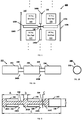
- Fig. 1 shows the components of a low-band radiator 100 of a dual band antenna where the radiating elements are oriented to produce vertical and horizontal polarization.
- Fig. 1 illustrates a portion or section 400 of an ultra-wideband, dual-band dual-polarization cellular basestation antenna comprising four high radiators 410, 420, 430, 440 arranged in a 2 ⁇ 2 matrix with a low-band radiator 100.
- a single low-band radiator 100 is interspersed at predetermined intervals with these four high band radiators 410, 420, 430, 440.
- the low-band radiator 100 comprises a horizontal dipole 120 and a vertical dipole 140.
- the vertical dipole is a conventional dipole 140 and the horizontal dipole 120 is an extended dipole configured in a crossed-dipole arrangement with crossed center feed 130.
- Center feed 130 comprises two interlocked, crossed printed circuit boards (PCB) having feeds formed on respective PCBs for dipoles 120, 140.
- the antenna feed may be a balun, of a configuration well known to those skilled in the art.
- the center feed 130 suspends the extended dipole 120 above a metal groundplane 110, by preferably a quarter wavelength.
- a pair of auxiliary radiating elements 150A and 150B such as tuned parasitic elements or dipoles, or driven dipoles, is located in parallel with the conventional dipole 140 at opposite ends of the extended dipole 120.
- the tuned parasitic elements may each be a dipole formed on a PCB with metallization formed on the PCB, an inductive element formed between arms of that dipole on the PCB.
- An inductive element may be formed between the metal arms of the parasitic dipoles 150A, 150B to adjust the phase of the currents in the dipole arms to bring these currents into the optimum relationship to the current in the driven dipole 140.
- the auxiliary radiating elements may comprise driven dipole elements. The dipole 140 and the pair of auxiliary radiating elements 150 together produce a desired narrower beamwidth.
- the dipole 140 is a vertical dipole with dipole arms 140A, 140B that are approximately a quarter wavelength ( ⁇ /4), and the extended dipole 120 is a horizontal dipole with dipole arms 120A, 120B that are approximately a half wavelength ( ⁇ /2) each.
- the antenna architecture depicted in Fig. 1 includes the low band radiator 100 of an ultra-wideband dual-band cellular basestation antenna having crossed dipoles 120, 140 oriented in the vertical and horizontal directions located at a height of about a quarter wavelength above the metal groundplane 110.
- This antenna architecture provides a horizontally polarized, desired or predetermined horizontal beamwidth and a wideband match over the band of interest.
- the pair of laterally displaced auxiliary radiating elements (e.g., parasitic dipoles) 150A, 150B together with the vertically oriented driven dipole 140 provides a similar horizontal beamwidth in vertical polarization.
- the low-band radiator may be used as a component in a dual-band antenna with an operating bandwidth greater than 30% and a horizontal beamwidth in the range 55° to 75°. Still further, the horizontal beamwidths of the two orthogonal polarizations may be in the range of 55 degrees to 75 degrees. Preferably, the horizontal beamwidths of the two orthogonal polarizations may be in the range of 60 degrees to 70 degrees. Most preferably, the horizontal beamwidths of the two orthogonal polarizations are approximately 65 degrees.
- the dipole 120 has anti-resonant dipole arms 120A, 120B of length of approximately ⁇ /2 with a capacitively coupled feed with an 18dB impedance bandwidth > 32% and providing a beamwidth of approximately 65 degrees.
- This is one component of a dual polarized element in a dual polar wideband antenna
- the single halfwave dipole 140 with the two parallel auxiliary radiating elements 150A, 150B provides the orthogonal polarization to signal radiated by extended dipole 120.
- the low-band radiator 100 of the ultra-wideband dual-band cellular basestation antenna is well suited for use in the 698-960 MHz cellular band. A particular advantage of this configuration is that this low band radiator 100 leaves unobstructed regions or clear areas of the groundplane where the high-band radiators of the ultra-wideband dual-band antenna can be located with minimum interaction between the low band and high band radiators.
- the low-band radiators 100 of the antenna 400 as described radiate vertical and horizontal polarizations.
- dual slant polarizations linear polarizations inclined at +45° and -45° to vertical
- This can be accomplished by feeding the vertical and horizontal dipoles of the low-band radiator from a wideband 180° hybrid (i.e., an equal-split coupler) well known to those skilled in the art.
- the crossed-dipoles 120 and 140 define four quadrants, where the high-band radiators 420 and 410 are located in the lower-left and lower-right quadrants, and the high-band radiators 440 and 430 are located in the upper-left and upper-right quadrants.
- the low-band radiator 100 is adapted for dual polarization and provides clear areas on a groundplane 110 of the dual-band antenna 400 for locating the high band radiators 410, 420, 430, 440 in the dual-band antenna 400.
- Ellipsis points indicate that a basestation antenna may be formed by repeating portions 400 shown in Fig. 1 .
- the wideband high-band radiators 440, 420 to the left of the centerline comprise one high band array and those high-band radiators 430, 410 to the right of the centerline defined by dipole arm s 140A and 140B comprise a second high band array. Together the two arrays can be used to provide MIMO capability in the high band.
- Each high-band radiator 410, 420, 430, 440 may be adapted to provide a beamwidth of approximately 65 degrees.
- each high-band radiator 410, 420, 430, 440 may comprise a pair of crossed dipoles each located in a square metal enclosure.
- the crossed dipoles are inclined at 45° so as to radiate slant polarization.
- the dipoles may be implemented as bowtie dipoles or other wideband dipoles. While specific configurations of dipoles are shown, other dipoles may be implemented using tubes or cylinders or as metallized tracks on a printed circuit board, for example.
- the low-band radiator (crossed dipoles with auxiliary radiating elements) 100 can be used for the 698-960 MHz band
- the high-band radiators 410, 420, 430, 440 can be used for the 1.7 GHz to 2.7 GHz (1710-2690 MHz) band.
- the low-band radiator 100 provides a 65 degree beamwidth with dual polarization (horizontal and vertical polarizations). Such dual polarization is required for basestation antennas.
- the conventional dipole 140 is connected to an antenna feed, while the extended dipole 120 is coupled to the antenna feed by a series inductor and capacitor.
- the low-band auxiliary radiating elements (e.g., parasitic dipoles) 150 and the vertical dipole 140 make the horizontal beamwidth of the vertical dipole 140 together with the auxiliary radiating elements 150 the same as that of the horizontal dipole 120.
- the antenna 400 implements a multi-band antenna in a single antenna. Beamwidths of approximately 65 degrees are preferred, but may be in the range of 60 degrees to 70 degrees on a single degree basis (e.g., 60, 61, or 62 degrees). This ultra-wideband, dual-band cellular basestation antenna can be implemented in a limited physical space.
- the low band radiators are desirably in the form of vertical and horizontal radiating components to leave an unobstructed space for placing the high-band radiators.
- an ultra-wideband 180° hybrid may be used to feed the horizontal and vertical components of a radiator of one band of an ultra-wideband dual-band dual-polarization cellular basestation antenna, e.g., the low band.
- Figs. 2 and 3 illustrate a dipole arm 200 of a low-band radiator 100 for use in an ultra-wideband dual-band dual-polarization cellular basestation antenna 400, where the dual bands comprise low and high bands.
- This dipole arm 200 may be used to implement one or more of dipole arms 120A, 120B, 140A, and 140B shown in Fig. 1 .
- the dipole arm 200 uses one or more RF chokes.
- the dipole arm comprises, in this example, three dipole segments 210, 220, 230 separated by two RF (coaxial) chokes 240A and 240B each interspersed between adjacent dipole segments 210, 220, 230 (from left to right the dipole arm components are 210, 240A, 220, 240B, 230).
- Each choke 240A and 240B provides an open circuit or a high impedance separating adjacent dipole segments to minimize induced high band currents in the low-band radiator 100 and consequent disturbance to the high band pattern.
- the choke 240A and 240B is resonant at or near the frequencies of the high band.
- the dipole arm 200 may be implemented with two or four dipole segments with respectively one or three RF chokes. Other numbers of dipole segments and related RF chokes may be practiced without departing from the scope of the invention.
- Fig. 3 which provides a cross-sectional view of the dipole arm 200 along its longitudinal extent, the coaxial chokes 240A and 240B being the gaps about the center conductor 250 between dipole segments 210, 220, 230 of the dipole arm 200.
- Each dipole segment 210 and 220 comprises an outer cylindrical conducting body 260 and 270, respectively, disposed about an inner center conductor 250.
- the rightmost dipole segment 280 is connected by a short-circuit connection 252C to the center conductor 250, but itself does not need the center conductor 250 beyond the short circuit connection 252C as the dipole segment 280 connects to the dipole feed as would a dipole without chokes.
- a dipole 120, 140 comprises two dipole arms 120A, 120B, 140A, 140B adapted for the low band and for connection to an antenna feed 130. At least one of the dipole arms 120A, 120B, 140A, 140B comprises at least one RF choke, and in the embodiment shown in Fig. 3 two coaxial chokes being the gaps in the outer cylindrical tube near 240A and 240B.
- Each dipole segment 210 and 220 is open circuited at one end of the cylindrical conducting body 260 and 270 and short circuited 252A and 252B, respectively, at the other end to the center conductor 250.
- the center conductor 250 may comprise short-circuit conductors 252A, 252B, 252C with center conductor segment 250 extending between short-circuit conductors 252A and 252B, and center conductor segment 250 extending between short-circuit conductors 252B and 252C.
- the components 252A, 250, 252B, 250, 252C may be a single integrated conducting body.
- Each coaxial choke 240A and 240B has a protruding portion of the center conductor 250 extending beyond the cylindrical conducting body 260 and 270.
- the chokes, being coaxial chokes, are the gaps in the outer conductor near locations 240A and 240B backed by the (approximately) quarter wave coaxial section. This gap interrupts the high band currents.
- each cylindrical conducting body 260, 270, and 280 has a length A and a diameter D.
- the short-circuit portions 252A, 252B, 252C have a thickness B.
- the diameter of center conductor 250 is C.
- the overall length of the dipole arm 200 comprising three dipole segments 260, 270, and 280 is length E.
- the dipole arm 200 may comprise at least two dipole segments 210, 220. Adjacent dipole segments 210 and 220 on the one hand and 220 and 230 on the other hand are spaced apart about the center conductor 250 so that there is a gap between the adjacent dipole segments 210, 220.
- the dimensions of the components of the coaxial chokes are such as to place the resonance of the coaxial choke 240A, 240B in the high band.
- the center conductor 250 may be an elongated cylindrical conducting body.
- the thickness or diameter C of the center conductor influences the bandwidth of the choke and may be adapted to minimize the high-band current over the whole of the high band thereby providing immunity from disturbance of the high-band radiation pattern by the low-band radiator 100 over the entire high-band bandwidth.
- the space between the cylindrical conducting body 260, 270, 280 and the center conductor 250 may be filled with air, as depicted in Fig. 3 .
- the space between the cylindrical conducting body 260, 270, 280 and the center conductor 250 may be filled or partly filled with dielectric material.
- the cylindrical conducting body 260, 270, 280 and the center conductor 250 of each dipole segment 210, 220, 230 have dimensions optimized so that the radiation pattern of the high band is largely undisturbed by the presence of the low-band radiator 100.
- the radiator 100 is adapted for the frequency range of 698-960 MHz.
- the dipole may be an extended dipole 120 and the radiator 100 may further comprise another dipole 140 comprising two dipole arms.
- the dipoles 120, 140 are configured in a cross configuration. Each dipole arm is resonant at approximately a quarter-wavelength ( ⁇ /4) and is adapted for connection to an antenna feed.
- the extended dipole 120 has anti-resonant dipole arms. Each dipole arm is of approximately a half-wavelength ( ⁇ /2).
- an ultra-wideband dual-band dual-polarization cellular base-station antenna 400 comprising at least one low-band radiator 100 and a number of high-band radiators 410, 420, 430, 440.
- the dual bands are low and high bands suitable for cellular communications.
- Each low-band radiator 100 is adapted for dual polarization and provides clear areas on a groundplane 110 of the dual-band antenna 400 for locating high band radiators 410, 420, 430, 440 in the dual-band antenna 400.
- the high band radiators 410, 420, 430, 440 are each adapted for dual polarization.
- the high-band radiators 410, 420, 430, 440 are configured in at least one array.
- the low-band radiator 100 is interspersed amongst the high-band radiators 410, 420, 430, 440 at predetermined intervals.
- the high-band radiators 410, 420, 430, 440 are adapted for the frequency range of 1710 to 2690 MHz.
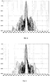
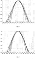
- Figs. 4 and 6 illustrate the superposition elevation and azimuth patterns for a high-band radiator(s) at a number of equally spaced frequencies across the high band where brass-tube dipole arms implement the low-band horizontal dipole
- Figs. 5 and 7 illustrate the corresponding elevation and azimuth patterns for a high-band radiator(s) where the low-band horizontal dipole is fitted with two chokes.
- the reduced level of sidelobes associated with the periodicity of the low-band elements where the chokes are used ( Fig. 5 ).
- the azimuth patterns are more stable with frequency with less tendency to flare out at wide angles.
- low-band radiators of an ultra-wideband dual-band dual-polarization cellular basestation antenna and such dual-band cellular base-station antennas described herein and/or shown in the drawings are presented by way of example only and are not limiting as to the scope of the invention.
- individual aspects and components of the hybrids may be modified, or may have been substituted therefore known equivalents, or as yet unknown substitutes such as may be developed in the future or such as may be found to be acceptable substitutes in the future.
Landscapes
- Engineering & Computer Science (AREA)
- Computer Networks & Wireless Communication (AREA)
- Physics & Mathematics (AREA)
- Electromagnetism (AREA)
- Variable-Direction Aerials And Aerial Arrays (AREA)
Claims (15)
- Radiateur de bande basse (100) d'une antenne de station de base cellulaire à double polarisation à double bande à ultra large bande (400), lesdites doubles bandes comprenant des bandes basse et haute, ledit radiateur de bande basse (100) comprenant :un premier dipôle de bande basse (120A, 120B) comprenant deux bras de dipôle de bande basse (200) adaptés pour ladite bande basse et une connexion à une source d'antenne ;un second dipôle de bande basse (140A, 140B) comprenant deux bras supplémentaires de dipôle de bande basse ;le radiateur de bande basse (100) étant caractérisé en ce queau moins un bras de dipôle de bande basse (200) dudit premier dipôle de bande basse comprend :au moins deux segments de dipôle de bande basse (210, 220, 230) ; etau moins une bobine d'arrêt (240A, 240B) radiofréquence (RF) disposée entre lesdits segments de dipôle de bande basse (210, 220, 230), chaque bobine d'arrêt constituant un circuit ouvert ou une impédance élevée et séparant des segments de dipôle de bande basse adjacents pour réduire les courants de bande haute induits dans ledit radiateur de bande basse (100) et une perturbation résultante du motif de bande haute, ladite bobine d'arrêt étant résonante aux fréquences, ou dans le voisinage des fréquences, de ladite bande haute,où le premier dipôle de bande basse (120A, 120B) et le second dipôle de bande basse (140A, 140B) sont configurées suivant une configuration croisée agencée de manière à définir quatre quadrants, etoù des radiateurs de bande haute (410, 420, 430, 440) résonants dans la bande haute sont positionnés dans les quatre quadrants.
- Radiateur de bande basse (100) tel que revendiqué dans la revendication 1, dans lequel chaque segment de dipôle de bande basse (210, 220, 230) comprend un corps allongé électriquement conducteur (260, 270, 280), ledit corps allongé étant en circuit ouvert à une extrémité et en court-circuit à l'autre extrémité au niveau d'un conducteur central (250).
- Radiateur de bande basse (100) tel que revendiqué dans la revendication 2, dans lequel ledit conducteur central (250) relie lesdites parties court-circuités (252A, 252B, 252C) desdits segments de dipôle de bande basse (210, 220, 230).
- Radiateur de bande basse (100) tel que revendiqué dans la revendication 2, dans lequel ladite au moins une bobine d'arrêt (240A, 240B) est une bobine d'arrêt coaxiale et chaque bobine d'arrêt coaxiale comprend une partie en saillie du conducteur central s'étendant d'un espace entre des segments de dipôle de bande basse adjacents, chaque bobine d'arrêt ayant une longueur d'un quart de longueur d'onde (λ/4), ou moins, à des fréquences situées dans la bande passante de la bande haute.
- Radiateur de bande basse (100) tel que revendiqué dans la revendication 1, dans lequel ladite bobine d'arrêt (240A, 240B) contient des éléments de circuit à constantes localisées, ou est une gaine ouverte renfermant partiellement ou complètement un conducteur central.
- Radiateur de bande basse (100) tel que revendiqué dans la revendication 1, dans lequel ledit au moins un bras de dipôle de bande basse (200) comprend trois segments de dipôle de bande basse (260, 270, 280) séparés par deux bobines d'arrêt (240A, 240B), les segments de dipôle adjacents étant espacés de manière à ce qu'il y ait un espace entre lesdits segments de dipôle de bande basse adjacents.
- Radiateur de bande basse (100) tel que revendiqué dans la revendication 3, comprenant ledit conducteur central (250) reliant lesdites court-circuités (252A, 252B) est un corps électriquement conducteur, cylindrique allongé, où ledit conducteur central (250) a une épaisseur adaptée pour se prémunir de la perturbation du motif de rayonnement de bande haute du radiateur de bande basse sur toute la bande passante de bande haute.
- Radiateur de bande basse (100) tel que revendiqué dans la revendication 1, adapté pour la plage de fréquences s'étendant de 698 à 960 MHz.
- Radiateur de bande basse (100) tel que revendiqué dans la revendication 1, dans lequel lesdits deux bras de dipôle de bande basse (120A, 120B) dudit premier dipôle de bande basse comprennent chacun au moins deux segments de dipôle de bande basse (210, 220), et au moins une bobine d'arrêt (240A) disposée entre lesdits segments de dipôle de bande basse.
- Radiateur de bande basse (100) tel que revendiqué dans la revendication 1, dans lequel ledit premier dipôle de bande basse (120A, 120B) est un dipôle de bande basse étendue, chaque bras de dipôle de bande basse résonant à environ un quart de longueur d'onde (λ/4), adapté pour une connexion à ladite source d'antenne (130), ledit dipôle de bande basse étendue (120A, 120B) ayant des bras de dipôle anti-résonnants, chaque bras de dipôle de bande basse d'environ une demi-longueur d'onde (λ/2).
- Radiateur de bande basse (100) tel que revendiqué dans la revendication 1, dans lequel les bras de dipôle de bande basse comprennent :un premier bras de dipôle de bande basse (120A) ;un second bras de dipôle de bande basse (120B) ; et où le radiateur bande basse (100) comprend en outre
une ligne d'alimentation (130) couplée aux premier et second bras de dipôle de bande basse (120A, 120B) ; où les premier et second bras de dipôle de bande basse (120A, 120B) comprennent en outre chacun un conducteur intérieur (250) et une pluralité de conducteurs externes discontinus (210, 220), la pluralité de conducteurs externes discontinus (210, 220) sont en circuit ouvert au niveau d'une première extrémité et en court-circuit à une seconde extrémité, où les conducteurs externes discontinus comprennent en outre une bobine de l'au moins une bobine d'arrêt (240A) radiofréquence (RF). - Radiateur de bande basse (100) tel que revendiqué dans la revendication 1, comprenant en outre :un dipôle vertical (140A, 140B),où le premier dipôle de bande basse (120A, 120B) et le dipôle vertical (140A, 140B) sont agencés pour produire une polarisation verticale et une polarisation horizontale.
- Radiateur de bande basse (100) tel que revendiqué dans la revendication 1, comprenant en outre :un dipôle vertical (140A, 140B), où l'au moins un bras de dipôle (200) dudit dipôle vertical comprend :au moins deux segments de dipôle de bande basse (210, 220, 230) ; etau moins une bobine d'arrêt (240A, 240B) radiofréquence (RF) disposée entre lesdits segments de dipôle de bande basse (210, 220, 230), chaque bobine d'arrêt constituant un circuit ouvert ou une impédance élevée et séparant des segments de dipôle bande basse adjacents pour réduire les courants de bande haute induits dans ledit radiateur bande basse (100) et une perturbation résultante du motif de bande haute, ladite bobine d'arrêt étant résonante aux fréquences, ou dans le voisinage des fréquences, de ladite bande haute.
- Antenne de station de base cellulaire à double polarisation à double bande à ultra large bande (400), lesdites doubles bandes étant des bandes basse et haute appropriées pour des communications cellulaires, ladite antenne à double bande étant caractérisé par :au moins un radiateur de bande basse (100), tel que revendiqué dans l'une quelconque des revendications 1 à 13, adapté pour une double polarisation et fournissant des zones claires sur un plan de masse (110) de ladite antenne à double bande pour localiser des radiateurs de bande haute dans ladite antenne à double bande ; etdes radiateurs de bande haute (410, 420, 430, 440), chacun adapté pour une double polarisation, lesdits radiateurs de bande haute étant configurés dans au moins un réseau, lesdits radiateurs de bande basse étant intercalés entre lesdits radiateurs de bande haute à des intervalles prédéterminés.
- Antenne de station de base cellulaire à double polarisation à double bande à ultra large bande (400) telle que revendiquée dans la revendication 14, où lesdits radiateurs de bande haute (410, 420, 430, 440) sont adaptés pour la plage de fréquences s'étendant de 1710 à 2690 MHz.
Applications Claiming Priority (1)
| Application Number | Priority Date | Filing Date | Title |
|---|---|---|---|
| PCT/CN2012/087300 WO2014100938A1 (fr) | 2012-12-24 | 2012-12-24 | Antennes de station de base cellulaire alternées double bande |
Publications (3)
| Publication Number | Publication Date |
|---|---|
| EP2769476A1 EP2769476A1 (fr) | 2014-08-27 |
| EP2769476A4 EP2769476A4 (fr) | 2015-06-17 |
| EP2769476B1 true EP2769476B1 (fr) | 2017-06-28 |
Family
ID=51019630
Family Applications (1)
| Application Number | Title | Priority Date | Filing Date |
|---|---|---|---|
| EP12881985.1A Active EP2769476B1 (fr) | 2012-12-24 | 2012-12-24 | Antennes de station de base cellulaire alternées double bande |
Country Status (5)
| Country | Link |
|---|---|
| US (3) | US9570804B2 (fr) |
| EP (1) | EP2769476B1 (fr) |
| CN (1) | CN104067527B (fr) |
| ES (1) | ES2639846T3 (fr) |
| WO (1) | WO2014100938A1 (fr) |
Cited By (1)
| Publication number | Priority date | Publication date | Assignee | Title |
|---|---|---|---|---|
| US11848492B2 (en) | 2015-12-10 | 2023-12-19 | Rfs Technologies, Inc. | Low band dipole and multi-band multi-port antenna arrangement |
Families Citing this family (41)
| Publication number | Priority date | Publication date | Assignee | Title |
|---|---|---|---|---|
| ES2639846T3 (es) | 2012-12-24 | 2017-10-30 | Commscope Technologies Llc | Antenas de estaciones base móviles intercaladas de doble banda |
| DE102013012305A1 (de) * | 2013-07-24 | 2015-01-29 | Kathrein-Werke Kg | Breitband-Antennenarray |
| CN107078390B (zh) * | 2014-11-18 | 2021-02-26 | 康普技术有限责任公司 | 用于多频带辐射阵列的掩蔽的低频带元件 |
| WO2016137526A1 (fr) * | 2015-02-25 | 2016-09-01 | CommScope Technologies, LLC | Réseau de dipôles pleine onde à performances d'angle de strabisme améliorées |
| WO2016204821A1 (fr) | 2015-06-15 | 2016-12-22 | Commscope Technologies Llc | Bras de dipôle obstrué |
| CN107275808B (zh) | 2016-04-08 | 2021-05-25 | 康普技术有限责任公司 | 超宽频带辐射器和相关的天线阵列 |
| US10680347B2 (en) | 2016-07-29 | 2020-06-09 | John Mezzalingua Associates, LLC | Low profile telecommunications antenna |
| CN109643839B (zh) | 2016-09-07 | 2021-02-19 | 康普技术有限责任公司 | 适合用于蜂窝和其它通信系统的多频带多波束透镜式天线 |
| CN110546813B (zh) | 2017-03-06 | 2021-07-13 | 约翰·梅扎林瓜联合股份有限公司 | 用于低轮廓电信天线的隐形布置结构 |
| US11569567B2 (en) | 2017-05-03 | 2023-01-31 | Commscope Technologies Llc | Multi-band base station antennas having crossed-dipole radiating elements with generally oval or rectangularly shaped dipole arms and/or common mode resonance reduction filters |
| US11322827B2 (en) | 2017-05-03 | 2022-05-03 | Commscope Technologies Llc | Multi-band base station antennas having crossed-dipole radiating elements with generally oval or rectangularly shaped dipole arms and/or common mode resonance reduction filters |
| US10770803B2 (en) | 2017-05-03 | 2020-09-08 | Commscope Technologies Llc | Multi-band base station antennas having crossed-dipole radiating elements with generally oval or rectangularly shaped dipole arms and/or common mode resonance reduction filters |
| WO2018213620A1 (fr) * | 2017-05-18 | 2018-11-22 | John Mezzalingua Associates, LLC | Antenne à affaiblissement rapide multibande comportant des dipôles masqués en forme de carte de circuit imprimé multicouche |
| CN109149131B (zh) | 2017-06-15 | 2021-12-24 | 康普技术有限责任公司 | 偶极天线和相关的多频带天线 |
| US11522298B2 (en) | 2017-07-07 | 2022-12-06 | Commscope Technologies Llc | Ultra-wide bandwidth low-band radiating elements |
| CN111373601B (zh) | 2017-10-26 | 2024-03-01 | 约翰梅扎林加瓜联合有限责任公司D/B/A Jma无线 | 多频带天线 |
| US10777891B2 (en) * | 2018-01-18 | 2020-09-15 | Swiftlink Technologies Inc. | Scalable radio frequency antenna array structures |
| US10756432B2 (en) * | 2018-02-13 | 2020-08-25 | Speedlink Technology Inc. | Antenna element structure suitable for 5G CPE devices |
| EP3537535B1 (fr) | 2018-03-07 | 2022-05-11 | Nokia Shanghai Bell Co., Ltd. | Système d'antennes |
| CN110752437A (zh) * | 2018-07-23 | 2020-02-04 | 康普技术有限责任公司 | 偶极臂 |
| CN112567574B (zh) * | 2018-08-03 | 2022-05-10 | 劲通开曼有限公司 | 用于隔离双极化天线中的正交信号路径并产生附加谐振的寄生元件 |
| CN110858679B (zh) * | 2018-08-24 | 2024-02-06 | 康普技术有限责任公司 | 具有宽带去耦辐射元件的多频带基站天线和相关辐射元件 |
| WO2020037662A1 (fr) * | 2018-08-24 | 2020-02-27 | 深圳大学 | Réseau d'antennes dipôles |
| CN110867642A (zh) | 2018-08-28 | 2020-03-06 | 康普技术有限责任公司 | 用于多频带天线的辐射元件以及多频带天线 |
| US11287835B2 (en) | 2019-03-21 | 2022-03-29 | Wing Aviation Llc | Geo-fiducials for UAV navigation |
| CN113795979B (zh) | 2019-03-26 | 2023-07-07 | 康普技术有限责任公司 | 用于基站天线的辐射元件 |
| US11327151B2 (en) * | 2019-06-24 | 2022-05-10 | Nxp B.V. | Ranging technology use for ultra-broadband communication in millimeter wave communication systems |
| CN112448155B (zh) | 2019-09-05 | 2022-03-11 | 华为机器有限公司 | 一种天线、天线阵列及通讯设备 |
| US11239544B2 (en) * | 2019-10-31 | 2022-02-01 | Commscope Technologies Llc | Base station antenna and multiband base station antenna |
| CN210692768U (zh) * | 2019-10-31 | 2020-06-05 | 康普技术有限责任公司 | 基站天线和多频带基站天线 |
| EP4070411A4 (fr) | 2019-12-19 | 2022-11-30 | Huawei Technologies Co., Ltd. | Appareil d'antenne et station de base |
| CN111082211A (zh) * | 2020-01-03 | 2020-04-28 | 广东通宇通讯股份有限公司 | 一种双极化高增益抗干扰天线单元以及天线阵列 |
| CN111641028B (zh) * | 2020-05-09 | 2022-08-12 | 东莞职业技术学院 | 双极化天线结构及其无线通信设备 |
| CN115769436A (zh) | 2020-05-15 | 2023-03-07 | 约翰梅扎林加瓜联合有限责任公司D/B/A Jma无线 | 具有预配置的遮挡以实现多个频段的辐射器的密集布局的天线辐射器 |
| US11399403B1 (en) | 2020-10-21 | 2022-07-26 | Sprint Communications Company Lp | Addition thresholds for wireless access nodes based on insertion loss |
| CA3202811A1 (fr) | 2020-12-21 | 2022-06-30 | John Mezzalingua Associates, LLC | Configuration de dipole decouple pour permettre une densite de tassement amelioree pour des antennes multibandes |
| US11605893B2 (en) | 2021-03-08 | 2023-03-14 | John Mezzalingua Associates, LLC | Broadband decoupled midband dipole for a dense multiband antenna |
| CN116742317A (zh) | 2022-03-01 | 2023-09-12 | 康普技术有限责任公司 | 具有包括基于超材料谐振器的偶极臂的宽带去耦辐射元件的基站天线 |
| CN117317576B (zh) * | 2023-11-29 | 2024-02-06 | 福建福大北斗通信科技有限公司 | 一种宽频带四臂螺旋天线 |
| US12671179B2 (en) | 2024-04-24 | 2026-06-30 | Apple Inc. | Electronic device with rear wall antenna parasitic |
| WO2025240540A1 (fr) | 2024-05-16 | 2025-11-20 | Outdoor Wireless Networks LLC | Antennes de station de base avec réseaux à bande basse comportant des éléments rayonnants à bande basse présentant des éléments monopolaires parasites |
Family Cites Families (23)
| Publication number | Priority date | Publication date | Assignee | Title |
|---|---|---|---|---|
| US4359743A (en) * | 1979-07-26 | 1982-11-16 | The United States Of America As Represented By The Secretary Of The Army | Broadband RF isolator |
| US5387919A (en) | 1993-05-26 | 1995-02-07 | International Business Machines Corporation | Dipole antenna having co-axial radiators and feed |
| JP2000236209A (ja) * | 1999-02-15 | 2000-08-29 | Nippon Telegr & Teleph Corp <Ntt> | アンテナ装置 |
| JP2001185938A (ja) * | 1999-12-27 | 2001-07-06 | Mitsubishi Electric Corp | 2周波共用アンテナ、多周波共用アンテナ、および2周波または多周波共用アレーアンテナ |
| US20030030591A1 (en) * | 2001-08-09 | 2003-02-13 | David Gipson | Sleeved dipole antenna with ferrite material |
| US6552692B1 (en) * | 2001-10-30 | 2003-04-22 | Andrew Corporation | Dual band sleeve dipole antenna |
| JP2003198410A (ja) | 2001-12-27 | 2003-07-11 | Matsushita Electric Ind Co Ltd | 通信端末装置用アンテナ |
| JP4184941B2 (ja) | 2003-12-12 | 2008-11-19 | Dxアンテナ株式会社 | 多周波数帯アンテナ |
| US7339542B2 (en) * | 2005-12-12 | 2008-03-04 | First Rf Corporation | Ultra-broadband antenna system combining an asymmetrical dipole and a biconical dipole to form a monopole |
| US7589684B2 (en) * | 2006-12-19 | 2009-09-15 | Bae Systems Information And Electronic Systems Integration Inc. | Vehicular multiband antenna |
| CN201134512Y (zh) * | 2007-10-30 | 2008-10-15 | 京信通信系统(中国)有限公司 | 宽频带环状双极化辐射单元及线阵天线 |
| EP2073309B1 (fr) * | 2007-12-21 | 2015-02-25 | Alcatel Lucent | Élément de rayonnement à double polarisation pour antennes de station de base cellulaire |
| EP2346114B1 (fr) * | 2008-09-22 | 2016-01-27 | KMW Inc. | Antenne bifréquence à double polarisation pour station de base de communication mobile |
| US8081130B2 (en) * | 2009-05-06 | 2011-12-20 | Bae Systems Information And Electronic Systems Integration Inc. | Broadband whip antenna |
| US8816925B2 (en) * | 2009-05-06 | 2014-08-26 | Bae Systems Information And Electronic Systems Integration Inc. | Multiband whip antenna |
| US20100311325A1 (en) * | 2009-06-03 | 2010-12-09 | Marshall Radio Telemetry, Inc. | Systems and methods for through-the-earth communications |
| US20110063190A1 (en) * | 2009-08-26 | 2011-03-17 | Jimmy Ho | Device and method for controlling azimuth beamwidth across a wide frequency range |
| CN201699136U (zh) * | 2009-12-30 | 2011-01-05 | 广东通宇通讯设备有限公司 | 一种宽频双极化天线辐射单元及天线 |
| US8593363B2 (en) * | 2011-01-27 | 2013-11-26 | Tdk Corporation | End-fed sleeve dipole antenna comprising a ¾-wave transformer |
| US8665163B2 (en) * | 2011-05-17 | 2014-03-04 | Bae Systems Information And Electronic Systems Integration Inc. | Wide band embedded armor antenna |
| EP2858173B1 (fr) * | 2012-05-29 | 2023-01-04 | Huawei Technologies Co., Ltd. | Unité de rayonnement d'antenne à double polarisation et antenne de station de base |
| ES2639846T3 (es) | 2012-12-24 | 2017-10-30 | Commscope Technologies Llc | Antenas de estaciones base móviles intercaladas de doble banda |
| CN104269649B (zh) * | 2014-09-19 | 2017-02-15 | 广东博纬通信科技有限公司 | 一种超宽频带多频段阵列天线 |
-
2012
- 2012-12-24 ES ES12881985.1T patent/ES2639846T3/es active Active
- 2012-12-24 WO PCT/CN2012/087300 patent/WO2014100938A1/fr not_active Ceased
- 2012-12-24 EP EP12881985.1A patent/EP2769476B1/fr active Active
- 2012-12-24 US US14/358,763 patent/US9570804B2/en not_active Expired - Fee Related
- 2012-12-24 CN CN201280044035.4A patent/CN104067527B/zh active Active
-
2016
- 2016-12-29 US US15/393,333 patent/US10644401B2/en not_active Ceased
-
2021
- 2021-03-25 US US17/212,346 patent/USRE50073E1/en active Active
Non-Patent Citations (1)
| Title |
|---|
| None * |
Cited By (1)
| Publication number | Priority date | Publication date | Assignee | Title |
|---|---|---|---|---|
| US11848492B2 (en) | 2015-12-10 | 2023-12-19 | Rfs Technologies, Inc. | Low band dipole and multi-band multi-port antenna arrangement |
Also Published As
| Publication number | Publication date |
|---|---|
| CN104067527B (zh) | 2017-10-24 |
| WO2014100938A1 (fr) | 2014-07-03 |
| US10644401B2 (en) | 2020-05-05 |
| US9570804B2 (en) | 2017-02-14 |
| CN104067527A (zh) | 2014-09-24 |
| USRE50073E1 (en) | 2024-08-06 |
| US20170110789A1 (en) | 2017-04-20 |
| US20150214617A1 (en) | 2015-07-30 |
| EP2769476A1 (fr) | 2014-08-27 |
| ES2639846T3 (es) | 2017-10-30 |
| EP2769476A4 (fr) | 2015-06-17 |
Similar Documents
| Publication | Publication Date | Title |
|---|---|---|
| USRE50073E1 (en) | Dual-band interspersed cellular basestation antennas | |
| EP2736117B1 (fr) | Antenne de station de base cellulaire double bande ultra-large bande | |
| US9711871B2 (en) | High-band radiators with extended-length feed stalks suitable for basestation antennas | |
| US20230114554A1 (en) | Ultra-wide bandwidth low-band radiating elements | |
| US9912076B2 (en) | Choked dipole arm | |
| US11271327B2 (en) | Cloaking antenna elements and related multi-band antennas | |
| CN110741508B (zh) | 具有交叉偶极子辐射元件的多频带基站天线 | |
| EP3440741B1 (fr) | Éléments rayonnants à bande ultra large et réseaux d'antennes associés | |
| US20200067197A1 (en) | Multi-band base station antennas having broadband decoupling radiating elements and related radiating elements | |
| US9722321B2 (en) | Full wave dipole array having improved squint performance | |
| US20170062940A1 (en) | Compact wideband dual polarized dipole | |
| US9083068B2 (en) | Ultra-wideband 180 degree hybrid for dual-band cellular basestation antenna | |
| AU2016250326B2 (en) | Multiband antenna | |
| US20250079724A1 (en) | Radiating element for base station antenna and base station antenna | |
| Wang et al. | Design of a compact wideband dual-polarized base-station antenna with stable radiation patterns |
Legal Events
| Date | Code | Title | Description |
|---|---|---|---|
| PUAI | Public reference made under article 153(3) epc to a published international application that has entered the european phase |
Free format text: ORIGINAL CODE: 0009012 |
|
| 17P | Request for examination filed |
Effective date: 20140327 |
|
| AK | Designated contracting states |
Kind code of ref document: A1 Designated state(s): AL AT BE BG CH CY CZ DE DK EE ES FI FR GB GR HR HU IE IS IT LI LT LU LV MC MK MT NL NO PL PT RO RS SE SI SK SM TR |
|
| RIN1 | Information on inventor provided before grant (corrected) |
Inventor name: ISIK, OZGUR Inventor name: SHANG, CHUNHUI Inventor name: JONES, BEVAN BERESFORD |
|
| RAP1 | Party data changed (applicant data changed or rights of an application transferred) |
Owner name: COMMSCOPE TECHNOLOGIES LLC |
|
| RA4 | Supplementary search report drawn up and despatched (corrected) |
Effective date: 20150519 |
|
| RIC1 | Information provided on ipc code assigned before grant |
Ipc: H01Q 5/321 20150101ALI20150512BHEP Ipc: H04B 3/00 20060101AFI20150512BHEP Ipc: H01Q 1/24 20060101ALI20150512BHEP Ipc: H01Q 21/30 20060101ALI20150512BHEP Ipc: H01Q 1/52 20060101ALI20150512BHEP Ipc: H01Q 5/42 20150101ALI20150512BHEP Ipc: H01Q 21/26 20060101ALI20150512BHEP |
|
| 17Q | First examination report despatched |
Effective date: 20160203 |
|
| DAX | Request for extension of the european patent (deleted) | ||
| STAA | Information on the status of an ep patent application or granted ep patent |
Free format text: STATUS: EXAMINATION IS IN PROGRESS |
|
| GRAP | Despatch of communication of intention to grant a patent |
Free format text: ORIGINAL CODE: EPIDOSNIGR1 |
|
| STAA | Information on the status of an ep patent application or granted ep patent |
Free format text: STATUS: GRANT OF PATENT IS INTENDED |
|
| INTG | Intention to grant announced |
Effective date: 20170206 |
|
| RIN1 | Information on inventor provided before grant (corrected) |
Inventor name: JONES, BEVAN BERESFORD Inventor name: SHANG, CHUNHUI Inventor name: ISIK, OZGUR |
|
| GRAS | Grant fee paid |
Free format text: ORIGINAL CODE: EPIDOSNIGR3 |
|
| GRAA | (expected) grant |
Free format text: ORIGINAL CODE: 0009210 |
|
| STAA | Information on the status of an ep patent application or granted ep patent |
Free format text: STATUS: THE PATENT HAS BEEN GRANTED |
|
| AK | Designated contracting states |
Kind code of ref document: B1 Designated state(s): AL AT BE BG CH CY CZ DE DK EE ES FI FR GB GR HR HU IE IS IT LI LT LU LV MC MK MT NL NO PL PT RO RS SE SI SK SM TR |
|
| REG | Reference to a national code |
Ref country code: GB Ref legal event code: FG4D |
|
| REG | Reference to a national code |
Ref country code: CH Ref legal event code: EP |
|
| REG | Reference to a national code |
Ref country code: AT Ref legal event code: REF Ref document number: 905668 Country of ref document: AT Kind code of ref document: T Effective date: 20170715 |
|
| REG | Reference to a national code |
Ref country code: IE Ref legal event code: FG4D |
|
| REG | Reference to a national code |
Ref country code: DE Ref legal event code: R096 Ref document number: 602012034095 Country of ref document: DE |
|
| REG | Reference to a national code |
Ref country code: ES Ref legal event code: FG2A Ref document number: 2639846 Country of ref document: ES Kind code of ref document: T3 Effective date: 20171030 |
|
| PG25 | Lapsed in a contracting state [announced via postgrant information from national office to epo] |
Ref country code: GR Free format text: LAPSE BECAUSE OF FAILURE TO SUBMIT A TRANSLATION OF THE DESCRIPTION OR TO PAY THE FEE WITHIN THE PRESCRIBED TIME-LIMIT Effective date: 20170929 Ref country code: NO Free format text: LAPSE BECAUSE OF FAILURE TO SUBMIT A TRANSLATION OF THE DESCRIPTION OR TO PAY THE FEE WITHIN THE PRESCRIBED TIME-LIMIT Effective date: 20170928 Ref country code: HR Free format text: LAPSE BECAUSE OF FAILURE TO SUBMIT A TRANSLATION OF THE DESCRIPTION OR TO PAY THE FEE WITHIN THE PRESCRIBED TIME-LIMIT Effective date: 20170628 Ref country code: FI Free format text: LAPSE BECAUSE OF FAILURE TO SUBMIT A TRANSLATION OF THE DESCRIPTION OR TO PAY THE FEE WITHIN THE PRESCRIBED TIME-LIMIT Effective date: 20170628 Ref country code: LT Free format text: LAPSE BECAUSE OF FAILURE TO SUBMIT A TRANSLATION OF THE DESCRIPTION OR TO PAY THE FEE WITHIN THE PRESCRIBED TIME-LIMIT Effective date: 20170628 |
|
| REG | Reference to a national code |
Ref country code: NL Ref legal event code: MP Effective date: 20170628 |
|
| REG | Reference to a national code |
Ref country code: LT Ref legal event code: MG4D |
|
| REG | Reference to a national code |
Ref country code: AT Ref legal event code: MK05 Ref document number: 905668 Country of ref document: AT Kind code of ref document: T Effective date: 20170628 |
|
| PG25 | Lapsed in a contracting state [announced via postgrant information from national office to epo] |
Ref country code: RS Free format text: LAPSE BECAUSE OF FAILURE TO SUBMIT A TRANSLATION OF THE DESCRIPTION OR TO PAY THE FEE WITHIN THE PRESCRIBED TIME-LIMIT Effective date: 20170628 Ref country code: BG Free format text: LAPSE BECAUSE OF FAILURE TO SUBMIT A TRANSLATION OF THE DESCRIPTION OR TO PAY THE FEE WITHIN THE PRESCRIBED TIME-LIMIT Effective date: 20170928 Ref country code: SE Free format text: LAPSE BECAUSE OF FAILURE TO SUBMIT A TRANSLATION OF THE DESCRIPTION OR TO PAY THE FEE WITHIN THE PRESCRIBED TIME-LIMIT Effective date: 20170628 Ref country code: NL Free format text: LAPSE BECAUSE OF FAILURE TO SUBMIT A TRANSLATION OF THE DESCRIPTION OR TO PAY THE FEE WITHIN THE PRESCRIBED TIME-LIMIT Effective date: 20170628 Ref country code: LV Free format text: LAPSE BECAUSE OF FAILURE TO SUBMIT A TRANSLATION OF THE DESCRIPTION OR TO PAY THE FEE WITHIN THE PRESCRIBED TIME-LIMIT Effective date: 20170628 |
|
| REG | Reference to a national code |
Ref country code: FR Ref legal event code: PLFP Year of fee payment: 6 |
|
| PG25 | Lapsed in a contracting state [announced via postgrant information from national office to epo] |
Ref country code: CZ Free format text: LAPSE BECAUSE OF FAILURE TO SUBMIT A TRANSLATION OF THE DESCRIPTION OR TO PAY THE FEE WITHIN THE PRESCRIBED TIME-LIMIT Effective date: 20170628 Ref country code: AT Free format text: LAPSE BECAUSE OF FAILURE TO SUBMIT A TRANSLATION OF THE DESCRIPTION OR TO PAY THE FEE WITHIN THE PRESCRIBED TIME-LIMIT Effective date: 20170628 Ref country code: EE Free format text: LAPSE BECAUSE OF FAILURE TO SUBMIT A TRANSLATION OF THE DESCRIPTION OR TO PAY THE FEE WITHIN THE PRESCRIBED TIME-LIMIT Effective date: 20170628 Ref country code: RO Free format text: LAPSE BECAUSE OF FAILURE TO SUBMIT A TRANSLATION OF THE DESCRIPTION OR TO PAY THE FEE WITHIN THE PRESCRIBED TIME-LIMIT Effective date: 20170628 Ref country code: SK Free format text: LAPSE BECAUSE OF FAILURE TO SUBMIT A TRANSLATION OF THE DESCRIPTION OR TO PAY THE FEE WITHIN THE PRESCRIBED TIME-LIMIT Effective date: 20170628 |
|
| PG25 | Lapsed in a contracting state [announced via postgrant information from national office to epo] |
Ref country code: SM Free format text: LAPSE BECAUSE OF FAILURE TO SUBMIT A TRANSLATION OF THE DESCRIPTION OR TO PAY THE FEE WITHIN THE PRESCRIBED TIME-LIMIT Effective date: 20170628 Ref country code: IS Free format text: LAPSE BECAUSE OF FAILURE TO SUBMIT A TRANSLATION OF THE DESCRIPTION OR TO PAY THE FEE WITHIN THE PRESCRIBED TIME-LIMIT Effective date: 20171028 Ref country code: PL Free format text: LAPSE BECAUSE OF FAILURE TO SUBMIT A TRANSLATION OF THE DESCRIPTION OR TO PAY THE FEE WITHIN THE PRESCRIBED TIME-LIMIT Effective date: 20170628 Ref country code: IT Free format text: LAPSE BECAUSE OF FAILURE TO SUBMIT A TRANSLATION OF THE DESCRIPTION OR TO PAY THE FEE WITHIN THE PRESCRIBED TIME-LIMIT Effective date: 20170628 |
|
| REG | Reference to a national code |
Ref country code: DE Ref legal event code: R097 Ref document number: 602012034095 Country of ref document: DE |
|
| PG25 | Lapsed in a contracting state [announced via postgrant information from national office to epo] |
Ref country code: DK Free format text: LAPSE BECAUSE OF FAILURE TO SUBMIT A TRANSLATION OF THE DESCRIPTION OR TO PAY THE FEE WITHIN THE PRESCRIBED TIME-LIMIT Effective date: 20170628 |
|
| PLBE | No opposition filed within time limit |
Free format text: ORIGINAL CODE: 0009261 |
|
| 26N | No opposition filed |
Effective date: 20180329 |
|
| REG | Reference to a national code |
Ref country code: CH Ref legal event code: PL |
|
| PG25 | Lapsed in a contracting state [announced via postgrant information from national office to epo] |
Ref country code: SI Free format text: LAPSE BECAUSE OF FAILURE TO SUBMIT A TRANSLATION OF THE DESCRIPTION OR TO PAY THE FEE WITHIN THE PRESCRIBED TIME-LIMIT Effective date: 20170628 |
|
| REG | Reference to a national code |
Ref country code: IE Ref legal event code: MM4A |
|
| PG25 | Lapsed in a contracting state [announced via postgrant information from national office to epo] |
Ref country code: LU Free format text: LAPSE BECAUSE OF NON-PAYMENT OF DUE FEES Effective date: 20171224 Ref country code: MT Free format text: LAPSE BECAUSE OF NON-PAYMENT OF DUE FEES Effective date: 20171224 |
|
| REG | Reference to a national code |
Ref country code: BE Ref legal event code: MM Effective date: 20171231 |
|
| PG25 | Lapsed in a contracting state [announced via postgrant information from national office to epo] |
Ref country code: IE Free format text: LAPSE BECAUSE OF NON-PAYMENT OF DUE FEES Effective date: 20171224 |
|
| PG25 | Lapsed in a contracting state [announced via postgrant information from national office to epo] |
Ref country code: BE Free format text: LAPSE BECAUSE OF NON-PAYMENT OF DUE FEES Effective date: 20171231 Ref country code: CH Free format text: LAPSE BECAUSE OF NON-PAYMENT OF DUE FEES Effective date: 20171231 Ref country code: LI Free format text: LAPSE BECAUSE OF NON-PAYMENT OF DUE FEES Effective date: 20171231 |
|
| PG25 | Lapsed in a contracting state [announced via postgrant information from national office to epo] |
Ref country code: HU Free format text: LAPSE BECAUSE OF FAILURE TO SUBMIT A TRANSLATION OF THE DESCRIPTION OR TO PAY THE FEE WITHIN THE PRESCRIBED TIME-LIMIT; INVALID AB INITIO Effective date: 20121224 Ref country code: MC Free format text: LAPSE BECAUSE OF FAILURE TO SUBMIT A TRANSLATION OF THE DESCRIPTION OR TO PAY THE FEE WITHIN THE PRESCRIBED TIME-LIMIT Effective date: 20170628 |
|
| PG25 | Lapsed in a contracting state [announced via postgrant information from national office to epo] |
Ref country code: CY Free format text: LAPSE BECAUSE OF NON-PAYMENT OF DUE FEES Effective date: 20170628 |
|
| PG25 | Lapsed in a contracting state [announced via postgrant information from national office to epo] |
Ref country code: MK Free format text: LAPSE BECAUSE OF FAILURE TO SUBMIT A TRANSLATION OF THE DESCRIPTION OR TO PAY THE FEE WITHIN THE PRESCRIBED TIME-LIMIT Effective date: 20170628 |
|
| PG25 | Lapsed in a contracting state [announced via postgrant information from national office to epo] |
Ref country code: TR Free format text: LAPSE BECAUSE OF FAILURE TO SUBMIT A TRANSLATION OF THE DESCRIPTION OR TO PAY THE FEE WITHIN THE PRESCRIBED TIME-LIMIT Effective date: 20170628 |
|
| PG25 | Lapsed in a contracting state [announced via postgrant information from national office to epo] |
Ref country code: PT Free format text: LAPSE BECAUSE OF FAILURE TO SUBMIT A TRANSLATION OF THE DESCRIPTION OR TO PAY THE FEE WITHIN THE PRESCRIBED TIME-LIMIT Effective date: 20170628 |
|
| PG25 | Lapsed in a contracting state [announced via postgrant information from national office to epo] |
Ref country code: AL Free format text: LAPSE BECAUSE OF FAILURE TO SUBMIT A TRANSLATION OF THE DESCRIPTION OR TO PAY THE FEE WITHIN THE PRESCRIBED TIME-LIMIT Effective date: 20170628 |
|
| STAA | Information on the status of an ep patent application or granted ep patent |
Free format text: STATUS: NO OPPOSITION FILED WITHIN TIME LIMIT |
|
| PGFP | Annual fee paid to national office [announced via postgrant information from national office to epo] |
Ref country code: ES Payment date: 20230102 Year of fee payment: 11 |
|
| P01 | Opt-out of the competence of the unified patent court (upc) registered |
Effective date: 20230530 |
|
| REG | Reference to a national code |
Ref country code: GB Ref legal event code: 732E Free format text: REGISTERED BETWEEN 20240815 AND 20240821 |
|
| REG | Reference to a national code |
Ref country code: DE Ref legal event code: R081 Ref document number: 602012034095 Country of ref document: DE Owner name: OUTDOOR WIRELESS NETWORKS LLC (A COMPANY ORGAN, US Free format text: FORMER OWNER: COMMSCOPE TECHNOLOGIES LLC, HICKORY, NC, US |
|
| REG | Reference to a national code |
Ref country code: ES Ref legal event code: FD2A Effective date: 20250206 |
|
| PG25 | Lapsed in a contracting state [announced via postgrant information from national office to epo] |
Ref country code: ES Free format text: LAPSE BECAUSE OF NON-PAYMENT OF DUE FEES Effective date: 20231225 |
|
| PGFP | Annual fee paid to national office [announced via postgrant information from national office to epo] |
Ref country code: GB Payment date: 20251229 Year of fee payment: 14 |
|
| PGFP | Annual fee paid to national office [announced via postgrant information from national office to epo] |
Ref country code: FR Payment date: 20251226 Year of fee payment: 14 |
|
| PGFP | Annual fee paid to national office [announced via postgrant information from national office to epo] |
Ref country code: DE Payment date: 20251229 Year of fee payment: 14 |